

Page 1
IMPORTANT FOR FUTURE REFERENCE
Owner’s Manual
Please complete this information and retain
this manual for the life of the equipment:
Model #: __________________________
Serial #: __________________________
Date Purchased: ___________________
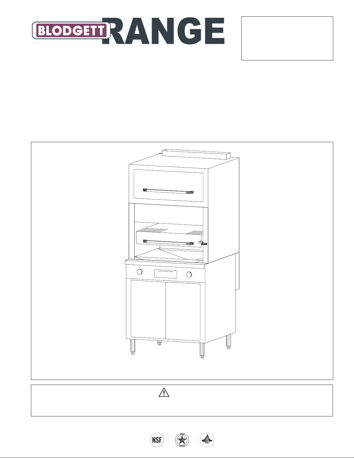
Radiant Broiler on Sectional Base
Model B32C-32B (Cabinet Base)
Model B32D-3240 (Standard-Oven Base)
Model B32A-3240 (Convection-Oven Base)
Model B32C-32B
WARNING
Improper installation, adjustment, alteration, service, or maintenance can cause property damage, injury, or death.
Read installation, operation, and maintenance instructions thoroughly before installing or servicing this equipment.
1100 Old Honeycutt Road, Fuquay-Varina, NC 27526 USA • www.blodgettrange.com
MANUAL 1184958
$18.00
RADIANT BROILER ON SECTIONAL BASE
MANUAL SECTION SR
Page 2

SAFETY PRECAUTIONS RADIANT BROILER ON SECTIONAL BASE
SAFETY PRECAUTIONS
Before installing and operating this equipment, be sure everyone involved in its operation is fully trained and aware of
precautions. Accidents and problems can be caused by failure to follow fundamental rules and precautions.
The following symbols, found throughout this manual, alert you to potentially dangerous conditions to the operator,
service personnel, or to the equipment.
DANGER
WARNING
CAUTION
NOTICE
This symbol warns of immediate hazards that will result in severe injury or death.
This symbol refers to a potential hazard or unsafe practice that could result in injury or
death.
This symbol refers to a potential hazard or unsafe practice that could result in injury,
product damage, or property damage.
This symbol refers to information that needs special attention or must be fully understood,
even though not dangerous.
WARNING
FIRE HAZARD
FOR YOUR SAFETY
Do not store or use gasoline or other flammable vapors and liquids in the vicinity of cooking appliances.
Keep area around cooking appliances free and clear of combustibles.
Purchaser of equipment must post in a prominent location detailed instructions to be followed in the event the
operator smells gas. Obtain the instructions from the local gas supplier.
WARNING
BURN HAZARD
Contact with hot surfaces will cause severe burns. Always use caution when operating cooking appliances.
WARNING
EXPLOSION AND ASPHYXIATION HAZARD
In the event a gas odor is detected, shut down equipment at the main gas shut-off valve and immediately call
the emergency phone number of your gas supplier.
Improper ventilation can result in headaches, drowsiness, nausea, and could result in death. Do not obstruct
the flow of combustion and ventilation air to and from cooking appliances.
WARNING
ELECTRIC SHOCK HAZARD
For appliances that use electric power, disconnect the power to the appliance before cleaning. Do not remove
panels that require tools to remove.
NOTICE
Blodgett Range Sectional Ranges are intended for commercial use only. Not for household use.
Warranty will be void if service work is performed by other than a qualified technician, or if other than genuine
Blodgett Range replacement parts are installed.
Give this Owner’s Manual and important papers to the proper authority to retain for future reference.
Copyright © 2002 by Blodgett Range. All rights reserved. Published in the United States of America.
PAGE 2 OF 16 OWNER'S MANUAL 1184958
Page 3

RADIANT BROILER ON SECTIONAL BASE INTRODUCTION
INTRODUCTION
Congratulations! You have purchased one of the finest pieces of heavy-duty commercial cooking equipment on the
market.
You will find that your new equipment, like all Blodgett Range equipment, has been designed and manufactured to
meet the toughest standards in the industry. Each piece of Blodgett Range equipment is carefully engineered and
designs are verified through laboratory tests and field installations. With proper care and field maintenance, you will
experience years of reliable, trouble-free operation. For best results, read this manual carefully.
RETAIN THIS MANUAL FOR FUTURE REFERENCE.
This manual is for the Blodgett Range Radiant Broilers that have a sectional base (models B32C-32B, B32D-3240,
and B32A-3240).
On models with oven bases, the serial plate is located on the backside of the kick-plate below the oven door. (To see
the serial plate, lift the kick-plate straight up and tilt the top edge out and down.) On the model with a cabinet base,
the serial plate is located inside the left cabinet door.
Read these instructions carefully before attempting installation. Installation and initial startup should be performed by
a qualified installer. Unless the installation instructions for this product are followed by a qualified service technician (a
person experienced in and knowledgeable with the installation of commercial gas an/or electric cooking equipment)
then the terms and conditions on the Manufacturer’s Limited Warranty will be rendered void and no warranty of any
kind shall apply.
In the event you have questions concerning the installation, use, care, or service of the product; write to:
Blodgett Range
1100 Old Honeycutt Road
Fuquay-Varina, North Carolina 27526 USA
OWNER'S MANUAL 1184958 PAGE 3 OF 16
Page 4

SPECIFICATIONS RADIANT BROILER ON SECTIONAL BASE
SPECIFICATIONS
NOTICE
Local codes regarding installation vary greatly from one area to another. The National Fire Protection Association,
Inc. states in its NFPA 96 latest edition that local codes are the “authority having jurisdiction” when it comes to
installation requirements for equipment. Therefore, installations should comply with all local codes.
Blodgett Range reserves the right to change specifications and product design without notice. Such revisions do
not entitle the buyer to corresponding changes, additions, or replacements for previously purchased equipment.
This product is intended for commercial use only, not for household use.
The installation must conform with local codes, or in the absence of local codes, with the National Fuel Gas Code,
ANSI Z223.1, Natural Gas Installation Code, CAN/CGA-B149.1, or the Propane Installation Code CAN/CGA-
B149.2, as applicable, including:
1. The appliance and its individual shutoff valve must be disconnected from the gas supply piping system during
any pressure testing of that system at test pressures in excess of 1/2 psi (3.45 kPa).
2. The appliance must be isolated from the gas supply piping system by closing its individual manual shutoff valve
during any pressure testing of the gas supply piping system at test pressures equal to or less than 1/2 psi (3.45
kPa).
WARNING
MINIMUM CLEARANCES FROM COMBUSTIBLE CONSTRUCTION
There must be adequate clearance between unit and combustible construction. Clearance must also be provided
for servicing and for operation.
Minimum clearance from combustible surfaces is 6" on the sides and back.
Units have 6" legs or casters, and may be installed on combustible floors.
Adequate clearance must be provided in the aisle and at the side and rear to allow the door to open sufficiently to
permit the removal of the racks and for serviceability.
On units with the convection-type oven, a minimum of 2 inches must be allowed behind the motor and the rear
non-combustible enclosure. Care must be taken to provide adequate air circulation to prevent the motor from
overheating. No additional clearance from the sides and back is required for service as the units are serviceable
from the front.
UTILITY REQUIREMENTS
GAS (see also page 6) ELECTRICITY (see also page 5)
Model
B32C-32B 110,000 90,000 - -
B32D-3240 155,000 132,000 1.0 1.0
B32A-3240 155,000 132,000 4.8 2.6
Natural Gas Propane 120V 208/240V
BTU/hour BTU/hour Amps Amps
PAGE 4 OF 16 OWNER'S MANUAL 1184958
Page 5

RADIANT BROILER ON SECTIONAL BASE SPECIFICATIONS
DIMENSIONS
Figure 1
THGIEW&SNOISNEMIDETARCGNIPPIHS
)"5.23sidetarcnunehwecnaraelcyrtne-rooD(
ledoMhtdiWthgieHhtpeDemuloVthgieW
5.54
0.38
B23-C23B
)6511(
5.54
0423-D23B
)6511(
5.54
0423-A23B
)6511(
0.55
)8012(
)8012(
0.38
0.55
)8012(
)8012(
0.38
0.55
)8012(
)8012(
tfuc2.021
)muc04.3(
tfuc2.021
)muc04.3(
tfuc2.021
)muc04.3(
38-3/4"
(984)
3-3/4"
(95)
TOP VIEW
2" (51)
32" (813)
Dimensions are in inches and (millimeters).
Model B32A-3240 is shown.
sbl553
)gk161(
sbl619
)gk514(
sbl559
)gk334(
Optional
Rear Gas
Connection
20"
(508)
7" (178)
2-1/2" (64)
Electrical
Connection
for Oven
Models
18"
(457)
REAR VIEW
37" (940)
36" (914)
Oven-base models
have a flue channel
that adds 1" to depth.
75"
(1905)
72"
(1829)
57-3/4"
(1467)
2-1/2" (64)
Front Gas Manifold
45"
(1143)
36"
(914)
FRONT VIEW
33-3/4"
(859)
SIDE VIEW
Motor for
Convection
Oven Model
ELECTRICITY SUPPLY
Both standard-oven and convection-oven models require electric power (50Hz or 60Hz single-phase AC). 120V
models have a 7-foot (2134 mm) power cord with a grounded plug. 208/240V models have a terminal block for
connection to a single-phase 208/240V source.
The appliance, when installed, must be electrically grounded in accordance with local codes, or in the absence of
local codes, with the National Electrical Code, ANSI/NFPA 70, or the Canadian Electrical Code, CSA C22.2, as
applicable. An electrical diagram is located on the inside of the oven kick plate.
OWNER'S MANUAL 1184958 PAGE 5 OF 16
Page 6

SPECIFICATIONS RADIANT BROILER ON SECTIONAL BASE
VENTILATION
WARNING
Improper ventilation can result in personal injury or death. Ventilation which fails to properly remove flue products
can cause headaches, drowsiness, nausea, or could result in death.
All units must be installed in such a manner that the flow of combustion and ventilation air is not obstructed.
Provisions for adequate air supply must be provided.
NOTICE
Proper ventilation is the owner’s responsibility. Any problem due to improper ventilation will not be covered by the
warranty.
Do not obstruct the front or rear of the unit since combustion air enters through these areas. Be sure to inspect
and clean the ventilation system according to the ventilation equipment manufacturer’s instructions.
If a ventilation canopy is used, it is recommended that the canopy extend 6" past the appliance and that the bottom
edge be located 6'6" from the floor. Filters should be installed at an angle of 45° or more from the horizontal. This
position prevents dripping grease and facilitates collecting the run-off grease in a drip pan, unusually installed with a
filter.
A strong exhaust fan tends to create a vacuum in the room and may interfere with burner performance or may
extinguish pilot flames. Fresh air openings approximately equal to the fan area will relieve such a vacuum. The
exhaust fan should be installed at least 2" above the vent opening at the top of the unit.
If the unit is connected directly to an outside flue, a CSA design certified down draft diverter must be installed.
In case of unsatisfactory performance on any appliance, check the appliance with the exhaust fan turned OFF. Do this
only long enough to check whether doing so corrects any problems with equipment performance. Then turn the
exhaust fan back on and let it run to remove any exhaust that may have accumulated during the test.
GAS SUPPLY
Each unit has a 1-1/4" front gas manifold that couples to the adjacent sectional unit(s), and can be ordered with an
optional 1" rear gas connection with a male NPT connector. Minimum supply pressure is 7" W.C. for natural gas, 11"
W.C. for propane. An external pressure regulator and shut off valve must be provided. If using a flexible-hose gas
connection, the I.D. of the hose must not be smaller than the connector on the unit and must comply with ANSI
Z21.69. Provide an adequate means of restraint to prevent undue strain on the gas connection.
These appliances are design-certified for operation on natural or propane gases. The unit is shipped configured and
adjusted for the type of gas specified by the purchaser. The serial plate indicates the type of gas the unit is equipped
to burn. The appliance should be connected ONLY to the type of gas for which it is equipped.
If applicable, the vent line from the gas appliance pressure regulator shall be installed to the outdoors in accordance
with local codes, or in the absence of local codes, with the National Fuel Gas Code, ANSI Z223.1, Natural Gas
Installation Code, CAN/CGA-B149.1, or the Propane Installation Code CAN/CGA-B149.2, as applicable.
An adequate gas supply is imperative. Undersized or low pressure lines will restrict the volume of gas required for
satisfactory performance. Fluctuations of more than 25% on natural gas or 10% on propane gas will create problems
and affect burner operating characteristics. A 1/8" pressure tap is located on the manifold to measure the manifold
pressure. The supply line to the unit should be no smaller than the inside diameter of the pipe on the unit to which it is
connected.
Purge the supply line to clean out dust, dirt, or other foreign matter before connecting the line to the unit.
All pipe joints and connections must be tested thoroughly for gas leaks. Use only soapy water for testing on all gases.
NEVER use an open flame to check for gas leaks. All connections must be checked for leaks after the unit has been
put into operation. Test pressure should not exceed 14" W.C.
PAGE 6 OF 16 OWNER'S MANUAL 1184958
Page 7

RADIANT BROILER ON SECTIONAL BASE OPERATION
OPERATION
DANGER
EXPLOSION HAZARD
In the event a gas odor is detected, shut down equipment at the main shut off valve. Immediately call the
emergency phone number of your gas supplier.
CAUTION
If the broiler pilots should go out the flow of gas to the broiler burners is NOT interrupted. Consequently, it is the
responsibility of the operator to check the ignition of the burners immediately EVERY TIME the broiler is turned on.
Should ignition fail after 10 seconds, turn off burners, wait 5 minutes, and then try again.
LIGHTING AFTER GAS HAS BEEN SHUT OFF
When turning on the main gas supply of a sectional range after it has been shut off, do the following:
1. Make sure that all the control valves and power switches of the range are in the OFF position.
2. Turn on the gas supply valve(s).
3. Light the standing pilots of each appliance.
4. Light ovens first, then wait six minutes before lighting top sections. This allows all air to be purged from the range.
OPERATION OF BROILER
The broiler grid is 24-1/2" wide by 28" deep, and rolls out 17-1/4". The front 3" of the grid receives less heat, and so
can be used as a holding area. As food cooks, drippings drain into a collection drawer that is out of the heat zone. To
operate the broiler, do the following (refer to Figure 2):
1. Light the constant-burning pilots located near the front of the broiler burners (unless the pilots are already lit).
2. Turn the burner control(s) to HIGH or LOW (as appropriate for the food to be cooked) and visually check that the
burners have ignited and have a steady flame.
3. Raise or lower the broiler rack to the height appropriate for the food to be cooked.
4. Pull out the broiler rack and place on the grate the food to be cooked. The front 3" of the grate receives less heat
and so can be used as a holding area.
5. When done broiling, turn the burner control knobs OFF (the constant-burning pilots will remain lit).
OPERATION OF WARMING OVEN
The warming oven is 25" wide and 25" deep, and is heated by flue gases from the broiler. Operating the broiler only
to heat the warming oven is inefficient and is not recommended.
OPERATION OF BASE OVEN
To operate the oven (of models that have an oven base), do the following (refer to Figure 2):
1. Turn the Oven Gas Valve to the OPEN position.
2. Move the Oven Power Switch to the "ON" position. The oven pilot will automatically light, and the oven burner will
come on (if the oven is below the set cooking temperature). The Cooking Light is lit when the power switch is on.
3. On convection-oven models, select the fan speed (HI or LOW) using the Fan-Speed Switch.
4. Select the desired oven cooking temperature using the Cooking Temperature dial.
5. When done cooking using the oven, move the Power Switch to OFF and turn the Oven Gas Valve to OFF.
Cooking tips for using a convection oven are included in the manual for the Saffire Series Sectional Range (1184743).
OWNER'S MANUAL 1184958 PAGE 7 OF 16
Page 8

OPERATION RADIANT BROILER ON SECTIONAL BASE
Figure 2
Controls
Warming Oven
(heated by flue gases)
3"
Front 3" of broiler
is a reduced-heat
Broiler Rack
(rolls out)
Broiler Burner Controls
(OFF-HIGH-LOW)
holding area.
Broiler Rack Height
Adjustment Lever
Oven Gas Valve
Broiler Drippings
Collection Drawer
Oven Power Switch
Fan-Speed Switcn
(for convection ovens)
Cooking Light
Cooking Temperature
Model B32A-3240
SHUTDOWN OF ENTIRE SECTIONAL RANGE
To place the sectional range in a standby state (ready for use), do the following:
1. Turn all manual control valves OFF.
2. Turn all thermostats to their lowest position.
To completely shut down the range for an extended period (or prior to disconnecting the gas supply), turn OFF the
manual shut-off valves of all gas supply connections to the sectional range. (This will extinguish all pilots.)
PAGE 8 OF 16 OWNER'S MANUAL 1184958
Page 9

RADIANT BROILER ON SECTIONAL BASE CLEANING & MAINTENANCE
CLEANING & MAINTENANCE
Blodgett Range equipment is sturdily constructed of the best materials and is designed to provide durable service
when treated with ordinary care. To expect the best performance, your equipment must be maintained in good
condition and cleaned daily. Naturally, the periods for this care and cleaning depend on the amount and degree of
usage.
Following daily and periodic maintenance procedures will enhance long life for your equipment. Climatic conditions
(such as salt air) may require more thorough and frequent cleaning or the life of the equipment could be adversely
affected.
Keep exposed, cleanable areas of unit clean at all times.
Daily:
■ Remove, empty, and clean drippings collection drawer.
■ Clean drippings drain chute.
Monthly:
■ Clean around burner air mixers and orifices if lint has accumulated.
■ Visually assure proper pilot operation.
BROILER
To prevent excess smoking, the grids, rack drip pan, and the other broiler components must be kept clean of food
remnants. Use a wire brush or similar scraping utensil. DO NOT use steel wool or similar scrub pad that will leave
small particles, which can get into food. The cleaning procedure is as follows:
1. Move the broiling rack to the low position. Pull out the rolling broiler rack.
2. Lift out the broiler grid and clean it with a wire brush or non-toxic solvent.
3. Remove the rack pan and clean.
4. With rolling rack pulled-out to its “stop,” raise front handle so rack's rollers will come through the notches in the
raising and lowering frame. Clean all parts where residue can collect.
5. Clean all parts of the raising and lowering frame.
6. Clean entire hopper section of all caked grease and residue.
7. Lubricate bearings with cooking oil.
8. Reverse procedure to reassemble broiling rack mechanism.
WARMING OVEN
To clean the warming oven, do the following:
1. Remove rack, bottom and burner baffle. Wash with a solution of hot water and a strong detergent or any other
non-toxic grease cutting solvents.
2. Wipe the sides, rear and top linings with the same solution.
3. Rinse with clear hot water.
4. Take care that any grease which may have collected in the flue vent collar is also removed.
5. Put baffle, bottom and rack back into oven.
BASE-OVEN INTERIOR
WARNING
FOR YOUR SAFETY, DISCONNECT THE POWER SUPPLY TO THE APPLIANCE BEFORE CLEANING.
WHEN CLEANING THE BLOWER WHEEL OF CONVECTION OVENS, BE SURE TO HAVE THE POWER
SWITCH IN THE “OFF” POSITION.
OWNER'S MANUAL 1184958 PAGE 9 OF 16
Page 10

CLEANING & MAINTENANCE RADIANT BROILER ON SECTIONAL BASE
Allow oven to cool. Remove porcelain enameled oven bottom. Clean by rubbing with strong detergent and Brillo pad
or similar scrubber. “Spill-overs” should be cleaned from the bottom as soon as possible to prevent carbonizing and a
“burnt-on” condition. For stubborn accumulations, commercial oven cleaners are recommended.
The porcelain oven door lining can be cleaned in a similar manner.
The side, rear and top lining should be wiped only with a cloth dampened with a mild detergent and water. Avoid using
excessive amounts of water, as this may drip into burner compartment and deteriorate the metal in that area. Do not
use strong commercial cleaners or abrasive pads on the side, rear or top linings, as they may damage the finish or
leave gray residue.
VENT SYSTEM
At least twice a year the unit venting system should be examined and cleaned.
STAINLESS-STEEL SURFACES
To remove normal dirt, grease and product residue from stainless steel surfaces that operate at LOW temperature,
use ordinary soap and water (with or without detergent) applied with a sponge or cloth. Dry thoroughly with a clean
cloth.
To remove BAKED-ON grease and food splatter, or condensed vapors; apply cleanser to a damp cloth or sponge and
rub cleanser on the metal in the direction of the polishing lines on the metal. Rubbing cleanser, as gently as possible,
in the direction of the polished lines will not mar the finish of the stainless steel. NEVER RUB WITH A CIRCULAR
MOTION. Soil and burnt deposits which do not respond to the above procedure can usually be removed by rubbing
the surface with SCOTCH-BRITE scouring pads or STAINLESS scouring pads. DO NOT USE ORDINARY STEEL
WOOL as any particles left on the surface will rust and further spoil the appearance of the finish. NEVER USE A
WIRE BRUSH, STEEL SCOURING PADS (EXCEPT STAINLESS), SCRAPER, FILE OR OTHER STEEL TOOLS.
Surfaces which are marred collect dirt more rapidly and become more difficult to clean. Marring also increases the
possibility of corrosive attack. Refinishing may then be required.
“Heat tint” is darkened areas that sometimes appear on stainless steel surfaces where the area has been subjected to
excessive heat. These darkened areas are caused by thickening of the protective surface of the stainless steel and
are not harmful. Heat tint can normally be removed by the foregoing, but tint which does not respond to this
procedure calls for a vigorous scouring in the direction of the polish lines using SCOTCH-BRITE scouring pads or a
STAINLESS scouring pad in combination with a powered cleanser. Heat tint may be lessened by reducing heat to
equipment during slack periods.
BLACK BAKED-ENAMEL SURFACES
Allow unit to cool somewhat after use and wash exterior with a hot, mild detergent or soap solution; particularly clean
off all grease deposits. Dry thoroughly with a dry cloth.
PAGE 10 OF 16 OWNER'S MANUAL 1184958
Page 11

RADIANT BROILER ON SECTIONAL BASE INSTALLATION
INSTALLATION
NOTICE
These installation procedures must be followed by qualified personnel or warranty will be void.
Local codes regarding installation vary greatly from one area to another. The National Fire Protection Association,
Inc. states in its NFPA 96 latest edition that local codes are the “authority having jurisdiction” when it comes to
installation requirements for equipment. Therefore, installations should comply with all local codes.
The installation must conform with local codes, or in the absence of local codes, with the National Fuel Gas Code,
ANSI Z223.1, Natural Gas Installation Code, CAN/CGA-B149.1, or the Propane Installation Code CAN/CGAB149.2, as applicable, including:
1. The appliance and its individual shutoff valve must be disconnected from the gas supply piping system during
any pressure testing of that system at test pressures in excess of 1/2 psi (3.45 kPa).
2. The appliance must be isolated from the gas supply piping system by closing its individual manual shutoff valve
during any pressure testing of the gas supply piping system at test pressures equal to or less than 1/2 psi (3.45
kPa).
IMMEDIATELY INSPECT FOR SHIPPING DAMAGE
All containers should be examined for damage before and during unloading. The freight carrier has assumed
responsibility for its safe transit and delivery. If damaged equipment is received, either apparent or concealed, a
claim must be made with the delivering carrier.
Apparent damage or loss must be noted on the freight bill at the time of delivery. The freight bill must then be
signed by the carrier representative (Driver). If the bill is not signed, the carrier may refuse the claim. The carrier
can supply the necessary forms.
A request for inspection must be made to the carrier within 15 days if there is concealed damage or loss that is not
apparent until after the equipment is uncrated. The carrier should arrange an inspection. Be certain to hold all
contents plus all packing material.
Follow the installation instructions in the Blodgett Range Saffire Sectional Ranges Owner's Manual (1184743) to
install the sectional range. The following installation steps should be added to that installation process.
INSTALLATION OF BROILER CERAMICS
The broiler ceramic tiles must be installed before operating the broiler. Do the following:
1. Locate and unwrap the 20 broiler ceramic tiles (they will have been shipped inside the oven).
2. Open the warming oven door and remove rack.
3. Lift front edge of warming oven bottom, slide forward and out of unit.
4. Lift the front of burner baffle (now visible below the oven bottom); lift up and forward out of the oven.
5. Place the ceramic tiles on both sides of both burners. The tile edges will rest on burner lips and side supports. Be
certain tiles are installed with cone-shaped projections pointing downward.
6. Replace the burner baffle.
7. Replace the warming oven bottom.
8. Replace the warming-oven rack and close the warming oven door.
INSTALLATION OF OPTIONAL BROILER WINGS
The optional broiler wings extend the sides of the broiler rearward to match the depth of a 42"-deep sectional range.
One or two wings (one for each side of the broiler) may have been ordered.
Models with an oven base have a flue channel on the back of the broiler. To install each wing, remove the top six #10
x 1/2 sheet metal screws from the appropriate side of the flue channel. Slip the flange of the broiler wing under the
flange of the flue channel. Align holes and secure by reinstalling six #10 x 1/2 sheet metal screws.
OWNER'S MANUAL 1184958 PAGE 11 OF 16
Page 12

INSTALLATION RADIANT BROILER ON SECTIONAL BASE
Models without an oven base do not have a flue channel on the back of the broiler. In this case, position each broiler
wing on the appropriate side of the rear of the broiler. Using the pre-punched holes in the broiler wing as a guide, drill
six 5/32” (0.156) diameter holes and secure the wing with six #10 x 1/2 sheet metal screws.
Figure 3
Installation of Optional Broiler Wings
CHECK OPERATION OF BROILER
When checking the operation of the installed sectional range, include the following items specific to the broiler:
1. Light the broiler pilots and check for correct flame height.
2. Turn on the two broiler burners and check for correct flame appearance and height.
PAGE 12 OF 16 OWNER'S MANUAL 1184958
Page 13

RADIANT BROILER ON SECTIONAL BASE SERVICE
SERVICE
WARNING
ADJUSTMENTS AND SERVICE WORK MAY BE PERFORMED ONLY BY A QUALIFIED TECHNICIAN WHO IS
EXPERIENCED IN, AND KNOWLEDGEABLE WITH, THE OPERATION OF COMMERCIAL COOKING
EQUIPMENT. TO ASSURE YOUR CONFIDENCE, CONTACT YOUR AUTHORIZED SERVICE AGENCY FOR
RELIABLE SERVICE, DEPENDABLE ADVICE OR OTHER ASSISTANCE, AND FOR GENUINE FACTORY
PARTS.
NOTICE
INSTALLATION OF OTHER THAN GENUINE BLODGETT RANGE PARTS WILL VOID THE WARRANTY ON
THIS EQUIPMENT.
The serial plate is located inside is located inside the kick-panel below the oven door on oven models, and inside the
base-cabinet door on cabinet-base models.
Replacement parts may be ordered either through a Blodgett Range Authorized Parts Distributor or a Blodgett Range
Authorized Service Agency.
When ordering parts, please supply the Model Number, Serial Number, Part Number, and Part Description.
For parts not listed, consult a Blodgett Range Authorized Parts Distributor or Blodgett Range Authorized Service
Agency. Consult the Blodgett Range Authorized Parts/Service Distributor list for the Authorized Parts supplier in your
area.
The broiler does not have a separate gas pressure regulator. It is connected directly to the front gas manifold of the
sectional range.
ADJUSTMENT OF BROILER PILOTS
The pilots are adjusted at the factory. If later the pilots are over-adjusted to the point where the flame is leaving its
port, or “blowing off,” the result is an unstable condition in which the pilot may extinguish. If necessary, adjust each
burner’s pilot using the following procedure:
1. If necessary, light the pilots.
2. Locate the pilot adjustment valves, which are part of the fitting that connects he pilot gas supply tubes to the gas
manifold of the burners. For each of the two pilots, turn the pilot adjustment screw to the left to increase the size
of the pilot flame, or to the right to decrease the size of the pilot flame. The flame should be about 1/2" high with a
slight yellow tip. The maximum pilot flame height is 3/4". The flame is too high if the yellow tip is producing black
streaks of carbon.
ADJUSTMENT OF BROILER BURNERS
To adjust the burner broilers, do the following:
1. To gain access to the burner air shutter, remove the small screens on the right and left sides of the broiler.
2. Turn the broiler control knobs to the full ON position to light the burners.
3. For each burner, loosen the two screws that hold the air shutter.
4. If a burner's flame is blowing or lifting off of the ports, close air shutter on front of burner until a stable flame is
obtained. If instead the flame is yellow-tipping, open the air shutter until a stable flame is obtained.
5. Re-tighten the screws that hold the air shutters.
6. Replace the small screens on the sides of the broiler.
OWNER'S MANUAL 1184958 PAGE 13 OF 16
Page 14

SERVICE RADIANT BROILER ON SECTIONAL BASE
Parts
Part Number Qty Description
2044 1
4368 1
4369 1
15698 1
1-3768SS 1
2401 1
2413 1
2414 1
1130399 2
1130398 2
1-5371 20
1021300 2
1160534 2
1172995 2
1006430 2
1006447 2
1038098 2
1161262 2
102 1
4440005 2
4440006 2
1173382 1
1173383 1
1173387 1
1171715 1
1-5962 1
1106814 1
HB605 1
WARMING OVEN BOTTOM
WARMING OVEN BOTTOM ANGLE LT
WARMING OVEN BOTTOM ANGLE RT
WARMING OVEN RACK
WARMING OVEN DOOR (STAINLESS STEEL)
FLUE BAFFLE ASSEMBLY
BURNER FRAME ASSEMBLY LT
BURNER FRAME ASSEMBLY RT
BURNER ASSEMBLY
BURNER VENTURI ASSEMBLY
CERAMIC
BURNER VALVE
KNOB
BURNER ORIFICE ASSEMBLY
BURNER ORIFICE #30 (for natural gas)
BURNER ORIFICE #47 (for propane)
PILOT (for natural gas)
PILOT (for propane)
BROILER RACK
INNER RACK BEARING KIT
OUTER RACK BEARING KIT
OUTER FRAME ASSEMBLY
RACK FRAME ASSEMBLY
RACK PAN
MECHANISM HANDLE ASSEMBLY
MECHANISM KNOB
INDEX PLATE
GREASE DRAWER
PAGE 14 OF 16 OWNER'S MANUAL 1184958
Page 15

RADIANT BROILER ON SECTIONAL BASE
Notes:
OWNER'S MANUAL 1184958 PAGE 15 OF 16
Page 16

RADIANT BROILER ON SECTIONAL BASE
RADIANT BROILER
ON SECTIONAL BASE
A product with the Blodgett Range name incorporates the best in durability and low maintenance. We all
recognize, however, that replacement parts and occasional professional service may be necessary to extend the
useful life of this unit. When service is needed, contact a Blodgett Range Authorized Service Agency, or your
dealer. To avoid confusion, always refer to the model number, serial number, and type of your unit.
Blodgett Range
1100 Old Honeycutt Road, Fuquay-Varina, NC 27526
www.blodgettrange.com
PAGE 16 OF 16 OWNER'S MANUAL 1184958
 Loading...