

Page 1

MARK V
CONVECTION OVEN
INSTALLATION - OPERATION - MAINTENANCE
MARK V
FOURS À CONVECTION
MANUEL D'INSTALLATION - FONCTIONNEMENT - ENTRETIEN
44 Lakeside Avenue, Burlington, Vermont 05401 USA Telephone: (802) 658Ć6600 Fax: (802)864Ć0183
BLODGETT OVEN COMPANY
www.blodgett.com
PN 17561 Rev U (6/11)
E 2011 - G.S. Blodgett Corporation
Page 2

IMPORTANT
WARNING: IMPROPER INSTALLATION, ADJUSTMENT, ALTERATION, SERVICE OR
MAINTENANCE CAN CAUSE PROPERTY DAMAGE, INJURY OR DEATH. READ THE
INSTALLATION, OPERATING AND MAINTENANCE INSTRUCTIONS THOROUGHLY
BEFORE INSTALLING OR SERVICING THIS EQUIPMENT
AVERTISSEMENT: UNE INSTALLATION, UN AJUSTEMENT, UNE ALTÉRATION, UN
SERVICE OU UN ENTRETIEN NON CONFORME AUX NORMES PEUT CAUSER DES
DOMMAGES À LA PROPRIÉTE, DES BLESSURES OU LA MORT. LISEZ ATTENTIVEĆ
MENT LES DIRECTIVES D'INSTALLATION, D'OPÉRATION ET D'ENTRETIEN AVANT
DE FAIRE L'INSTALLATION OU L'ENTRETIEN DE CET ÉQUIPEMENT.
FOR YOUR SAFETY
Do not store or use gasoline or other flammable vapors or liquids in the vicinity
of this or any other appliance.
AVERTISSEMENT
Ne pas entreposer ni utiliser de l'essence ni d'autres vapeurs ou liquides inflamĆ
mables dans le voisinage de cet appariel, ni de tout autre appareil.
The information contained in this manual is important for the proper installation,
use, and maintenance of this oven. Adherence to these procedures and instrucĆ
tions will result in satisfactory baking results and long, trouble free service.
Please read this manual carefully and retain it for future reference.
Les informations données dans le présent manuel sont importantes pour installer,
utiliser et entretenir correctement ce four. Le respect de ces instructions et procéĆ
dures permettra d'obtenir de bons résultats de cuisson et une longue durée de serĆ
vice sans problèmes. Veuillez lire le présent manuel et le conserver pour pouvoir
vous y reporter à l'avenir.
Errors: Descriptive, typographic or pictorial errors are subject to correction. SpecificaĆ
tions are subject to change without notice.
Erreurs:Les erreurs de description, de typographie ou d'illustration font l'objet de
corrections. Les caractéristiques sont sujettes à modifications sans préavis.
Page 3

THE REPUTATION YOU CAN COUNT ON
UNE RÉPUTATION SUR LAQUELLE VOUS POUVEZ COMPTER
For over a century and a half, The Blodgett Oven Company has been building
ovens and nothing but ovens. We've set the industry's quality standard for all
kinds of ovens for every foodservice operation regardless of size, application
or budget. In fact, no one offers more models, sizes, and oven applications
than Blodgett; gas and electric, fullĆsize, halfĆsize, countertop and deck, conĆ
vection, Cook'n Hold, CombiĆOvens and the industry's highest quality Pizza
Oven line. For more information on the full line of Blodgett ovens contact your
Blodgett representative.
Cela fait maintenant dessus un siècle et demi que Blodgett se spécialise dans
la fabrication de fours. Nous avons établi les normes de qualité qui s'appliĆ
quent dans l'industrie à tous les types de fours utilisés dans les services aliĆ
mentaires, quel qu'en soit la taille, l'exploitation ou le budget. En fait, ni n'offre
plus de modèles, de tailles et d'applications de fours que Blodgett. À gaz et
électriques. De tailles différentes, sur plan de travail et superposables. Qu'il
s'agisse de fours à convection, des modèles Cook'n Hold et CombiĆOven, ou
de la gamme de fours à pizzas de la plus haute qualité offerte sur le marché.
Pour de plus amples informations sur la gamme complète de fours Blodgett,
veuillez contacter votre représentant Blodgett.
Page 4

Your Service Agency's Address:
Adresse de votre agence de service:
Model/Modèl:
Serial Number/Numéro de série:
Your oven was installed by/
Installateur de votre four:
Your oven's installation was checked by/
Contrôleur de l'installation de votre four:
Page 5

Table of Contents/Table des Matières
Introduction
Oven Description and Specifications 2. . . .
Oven Components 3. . . . . . . . . . . . . . . . . . . .
Installation
Delivery and Location 4. . . . . . . . . . . . . . . . .
Oven Assembly 5. . . . . . . . . . . . . . . . . . . . . .
NSF Bolts 5. . . . . . . . . . . . . . . . . . . . . . . . . .
Leg Attachment 6. . . . . . . . . . . . . . . . . . . . .
Caster Assembly 6. . . . . . . . . . . . . . . . . . . .
Double Section Assembly 7. . . . . . . . . . . .
Oven Leveling 7. . . . . . . . . . . . . . . . . . . . . .
Utility Connections - Standards
and Codes 8. . . . . . . . . . . . . . . . . . . . . . . . . . .
Electrical Connection 9. . . . . . . . . . . . . . . . .
Initial Startup 10. . . . . . . . . . . . . . . . . . . . . . . . .
Operation
Safety Information 11. . . . . . . . . . . . . . . . . . . .
Solid State Manual Control 12. . . . . . . . . . . . .
Solid State Manual Control with
Digital Timer 13. . . . . . . . . . . . . . . . . . . . . . . . .
Solid State Digital Control 14. . . . . . . . . . . . . .
Blodgett IQ2T Vision Control 16. . . . . . . . . .
How Cook and Hold Works 26. . . . . . . . . . . .
General Guidelines for Operating
Personnel 27. . . . . . . . . . . . . . . . . . . . . . . . . . . .
Suggested Times and Temperatures 28. . . .
Maintenance
Introduction
Description et Spécifications du Four 31. . . .
Éléments du Four 32. . . . . . . . . . . . . . . . . . . . .
Installation
Livraison et Implantation 33. . . . . . . . . . . . . . .
Montage du Four 34. . . . . . . . . . . . . . . . . . . . .
Boulons NSF 34. . . . . . . . . . . . . . . . . . . . . . .
Assemblage des Pieds 35. . . . . . . . . . . . . . .
Montage des Roulettes 35. . . . . . . . . . . . . .
Montage de la Section Double 36. . . . . . . .
Mise à Niveau du Four 36. . . . . . . . . . . . . . .
Branchements de Service - Normes et
Codes 37. . . . . . . . . . . . . . . . . . . . . . . . . . . . . . .
Raccordement Électrique 38. . . . . . . . . . . . . .
Mise en Marche Initiale 39. . . . . . . . . . . . . . . .
Utilisation
Informations de Sécurité 40. . . . . . . . . . . . . . .
Commandes Standard 41. . . . . . . . . . . . . . . .
Commandes Standard avec le
Temporisateur Numérique 42. . . . . . . . . . . . .
Commandes Numériques à
SemiĆConducteurs 43. . . . . . . . . . . . . . . . . . . .
Blodgett IQ2T Commande Vision 46. . . . . .
Principe de la Fonction de Cuisson
et Maintien 57. . . . . . . . . . . . . . . . . . . . . . . . . . .
Consignes Générales à l'Intention
des Utilasateurs 58. . . . . . . . . . . . . . . . . . . . . .
Durées et Températures Suggérées 59. . . . .
Cleaning and Preventative Maintenance 29.
Troubleshooting Guide 30. . . . . . . . . . . . . . . .
Entretien
Nettoyage et Entretien Préventif 60. . . . . . . .
Guide de Détection des Pannes 61. . . . . . . .
Page 6

Introduction
Oven Description and Specifications
Cooking in a convection oven differs from cooking
in a conventional deck or range oven since heated
air is constantly recirculated over the product by
a fan in an enclosed chamber. The moving air conĆ
tinually strips away the layer of cool air surroundĆ
ing the product, quickly allowing the heat to peneĆ
trate. The result is a high quality product, cooked
at a lower temperature in a shorter amount of time.
Blodgett convection ovens represent the latest adĆ
vancement in energy efficiency, reliability, and
ease of operation. Heat normally lost, is recircuĆ
lated within the cooking chamber before being
vented from the oven: resulting in substantial reĆ
ductions in energy consumption and enhanced
oven performance.
Blodgett Electric Convection Ovens
ELECTRICAL SPECIFICATIONS (per section)
KW Hz Volts Phase
L1 L2 L3 N
U.S. and Canadian installations
11.0 60 208 1 51 - 51 - 6 AWG
11.0 60 208 3 31 29 29 - 8 AWG
11.0 60 220Ć240 1 44 - 44 - 6 AWG
11.0 60 220Ć240 3 26 24 24 - 8 AWG
11.0 60 440 3 15 14 14 - 12 AWG
11.0 60 480 3 14 13 13 - 12 AWG
General Export installations
11.0 50 208 3 18 18 18 4 Size per local code
11.0 50 220Ć240 1 48 - - 48 Size per local code
11.0 50 220/380 3 18 16 16 2 Size per local code
11.0 50 240/415 3 18 14 14 4 Size per local code
11.0 50 230/400 3 18 15 15 3 Size per local code
Amps
Air Flow Pattern for
Figure 1
Electrical Connection
(minimum size)
2
Page 7
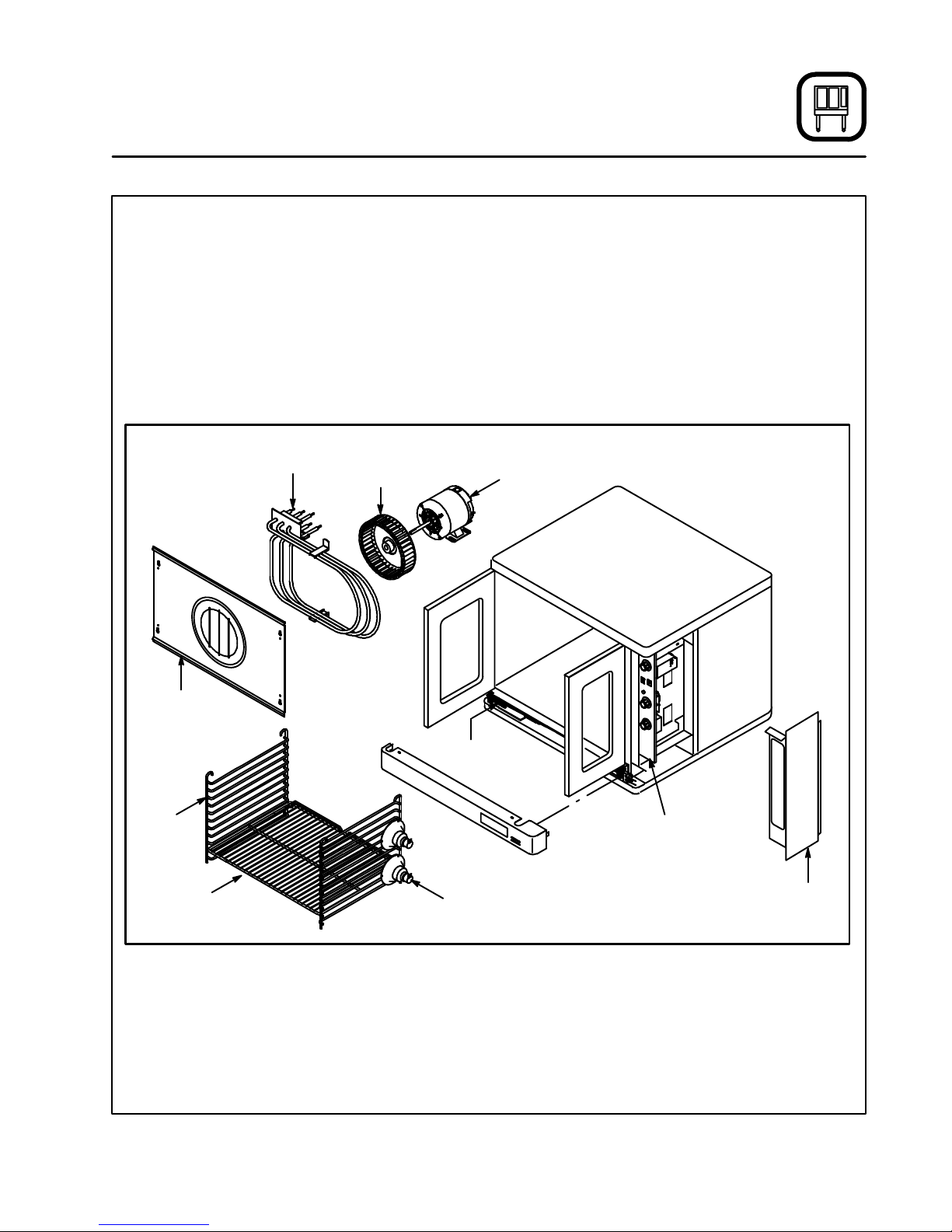
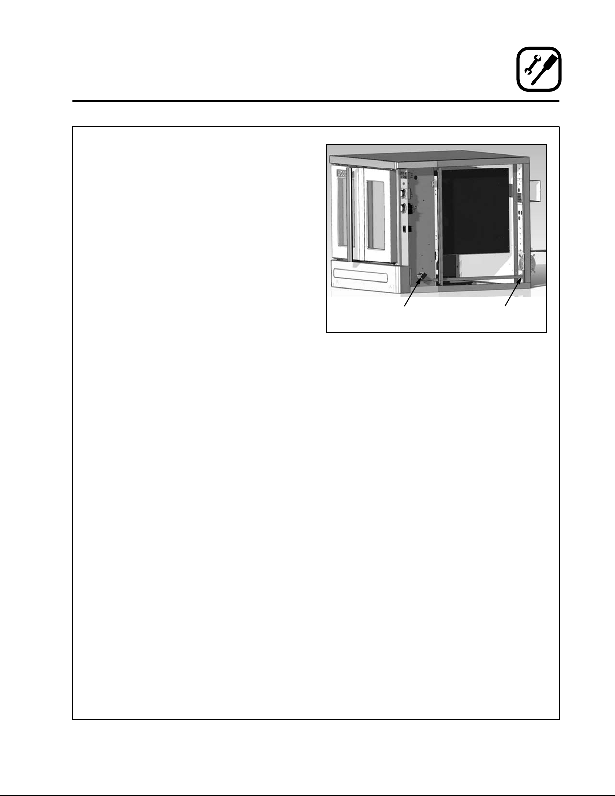
Introduction
Oven Components
Heating Elements - located on the back wall of
the oven, the elements provide heat to the baking
chamber on electric ovens.
Chain & Turnbuckle - controls operation of the
oven doors.
Control Panel - contains wiring and components
to control the oven operation.
Oven Racks - five racks are provided standard.
Additional racks are available.
Heating
Elements
Blower
Wheel
Rack Supports - hold oven racks.
Baffle - located on the back interior wall of the
oven. Protects the blower wheel.
Blower Wheel - spins to circulate hot air in the
baking chamber.
Convection Motor - provides power to turn the
blower wheel.
Oven Lights - provide lighting inside the baking
compartment.
Convection
Motor
Blower
Wheel Cover
Rack
Support
Oven Rack
Chain &
Turnbuckle
Oven Lights
Figure 2
Control
Panel
Control
Panel Cover
3
Page 8

Installation
Delivery and Location
DELIVERY AND INSPECTION
All Blodgett ovens are shipped in containers to
prevent damage. Upon delivery of your new oven:
D Inspect the shipping container for external damĆ
age. Any evidence of damage should be noted
on the delivery receipt which must be signed by
the driver.
D Uncrate the oven and check for internal damĆ
age. Carriers will accept claims for concealed
damage if notified within fifteen days of delivery
and the shipping container is retained for inĆ
spection.
The Blodgett Oven Company cannot assume
responsibility for loss or damage suffered in
transit. The carrier assumed full responsibility
for delivery in good order when the shipment
was accepted. We are, however, prepared to
assist you if filing a claim is necessary.
OVEN LOCATION
The well planned and proper placement of your
oven will result in long term operator convenience
and satisfactory performance.
The following clearances must be maintained beĆ
tween the oven and any combustible or nonĆcomĆ
bustible construction.
D Oven body right side - 1" (2.5 cm)
D Oven body left side - 1" (2.5 cm)
D Oven body back - 1" (2.5 cm)
D Oven body bottom - 1/2" (1.2 cm)
The following clearances must be available for serĆ
vicing.
D Oven body sides - 12" (30 cm)
D Oven body back - 12" (30 cm)
It is essential that an adequate air supply to the
oven be maintained to provide a sufficient flow of
combustion and ventilation air.
D Place the oven in an area that is free of drafts.
D Keep the oven area free and clear of all combusĆ
tibles such as paper, cardboard, and flammable
liquids and solvents.
D Do not place the oven on a curb base or seal to
a wall. This will restrict the flow of air and prevent
proper ventilation. Tripping of the blower moĆ
tor's thermal overload device is caused by an
excessive ambient temperature on the right
side of the oven. This condition must be corĆ
rected to prevent permanent damage to the
oven.
Before making any utility connections to this oven,
check the rating plate to be sure the oven specifiĆ
cations are compatible with the electrical services
supplied for the oven.
1. The rating plate is located on the underside of
the upper ledge above the right hand door.
4
Page 9
Installation
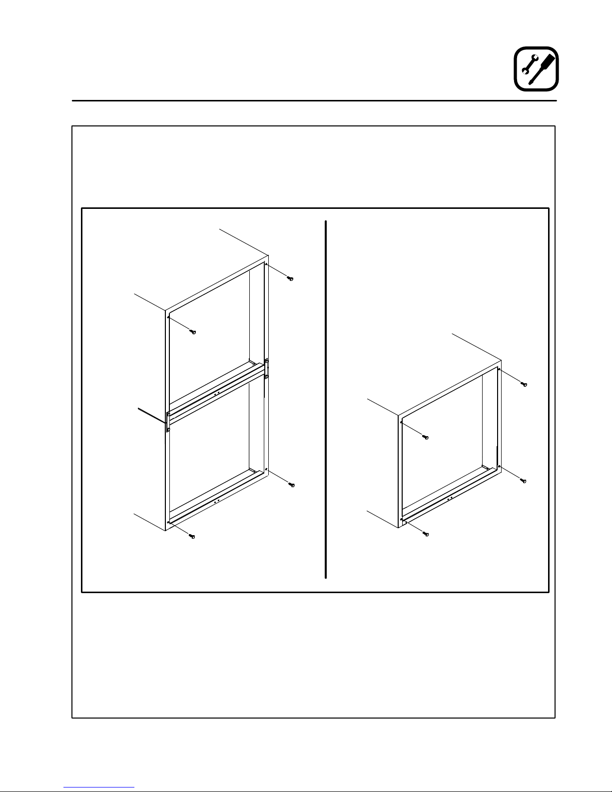
Oven Assembly
NSF BOLTS
These bolts are required by NSF to block any exĆ
posed hole on the back of an oven. This includes:
D any unit, single or stacked, without a back panel.
D any holes in stacked units not used for mountĆ
ing stacking brackets.
1. Locate the 5/16" bolts that were shipped with
the oven.
2. Install the bolts as shown in Figure 3.
Double Stacked Units Units without back panels
Figure 3
5
Page 10
Installation
Oven Assembly
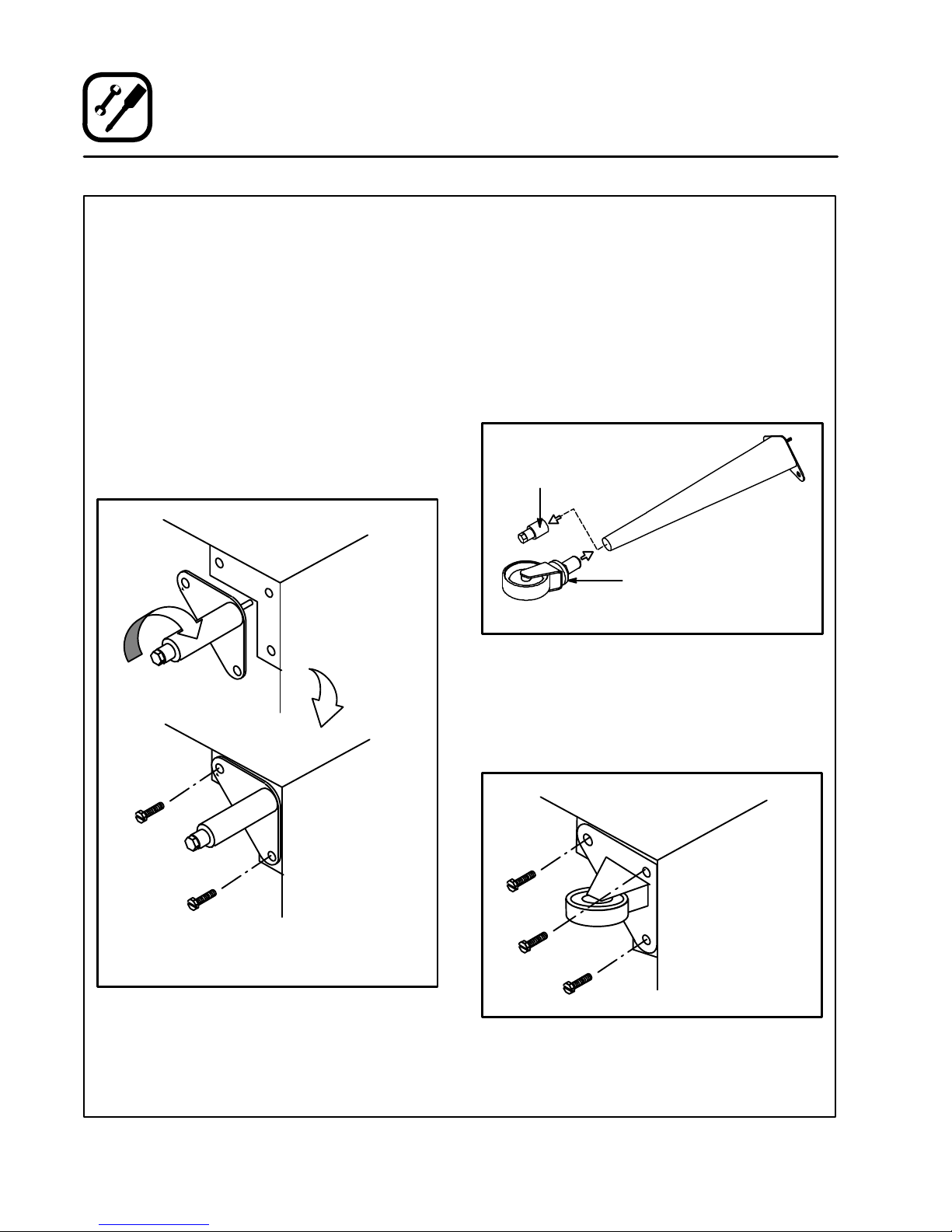
LEG ATTACHMENT
1. Push the oven onto a lift with the bottom of the
oven down.
2. Align the threaded stud in each leg with the
nut located inside each bottom corner of the
oven frame. Turn the legs clockwise and tightĆ
en to the nearest full turn.
3. Align the two leg plate holes in each leg with
those in the oven bottom. Secure each leg usĆ
ing two 1/2" bolts.
NOTE: If using casters see CASTER ASĆ
SEMBLY before proceeding.
4. Level the oven by screwing the adjustable leg
feet in or out as necessary.
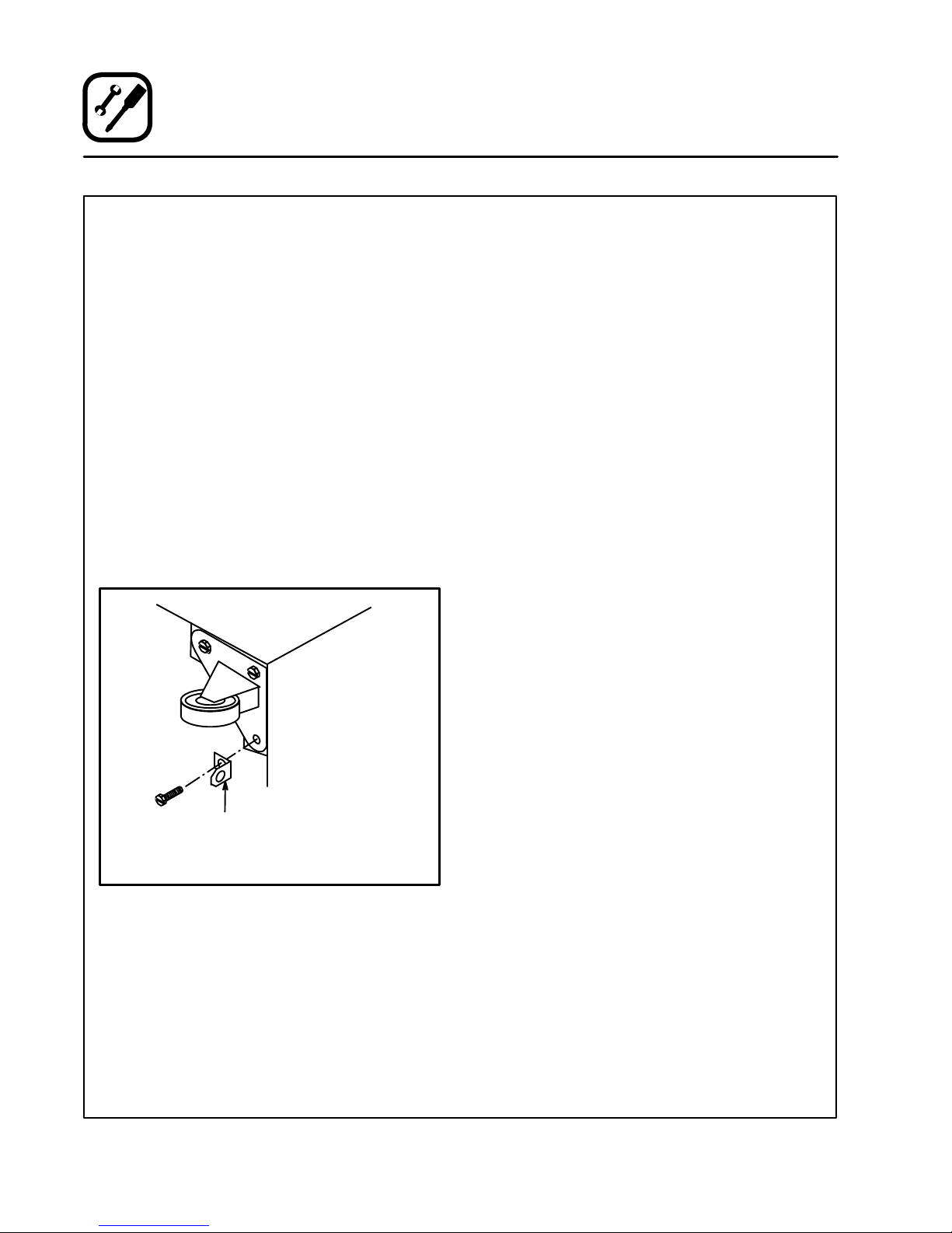
CASTER ASSEMBLY
NOTE: Install the locking casters on the front of
the oven. Install the nonĆlocking casters on
the back of the oven.
Casters for Single and Double Stacked Ovens:
1. Attach the legs as described.
2. Pry the adjustable feet out of the legs
3. Insert one caster into each leg as shown.
Tighten the lock nuts to secure the casters.
Adjustable
Leg Foot
Caster Assembly
25" (64 cm) Legs Shown
Figure 5
6" (15 cm) Legs Shown
Figure 4
Low Profile Casters for Double Stacked Ovens:
1. Align the three holes in each caster assembly
plate with those in the oven bottom. Secure
each caster using three 1/2" bolts.
Figure 6
6
Page 11
Installation
Oven Assembly
DOUBLE SECTION ASSEMBLY
NOTE: Old style ovens refer to units with painted exĆ
posed rear angle. New style ovens refer to
units with rear angle iron enclosed in steel.
The following instructions apply to stacking two
new style ovens.
1. Secure the short legs to the bottom sections
as described.
2. Place the upper section in position on top of
the lower oven.
3. Attach the stacking brackets using the reĆ
maining 5/16" bolts shipped with the ovens.
4. Attach the flue connector.
The following instructions apply to stacking a new
style oven on an old style oven.
1. Secure the short legs to the bottom sections
as described.
2. Place the upper section in position on top of
the lower oven.
3. Attach the stacking brackets using the reĆ
maining 5/16" bolts shipped with the ovens.
4. Drill a clearance hole for a 5/16" bolt in the
angle iron of the old style oven. Use the holes
in the stacking brackets as a pilot.
5. Attach the stacking brackets to the old style
oven with the 5/16" bolts and nuts provided in
the kit.
6. Attach the flue connector.
WARNING!!
When stacking ovens be sure to remove
the single oven flue boxes prior to attachĆ
ing threeĆpiece connector.
OVEN LEVELING
After assembly, the oven should be leveled and
moved to the operating location.
1. The oven can be leveled by adjusting the feet
or casters located on the bottom of each leg.
Flue
Connector
Figure 7
7
Page 12
Installation
Utility Connections - Standards and Codes
THE INSTALLATION INSTRUCTIONS CONĆ
TAINED HEREIN ARE FOR THE USE OF QUALIĆ
FIED INSTALLATION AND SERVICE PERSONNEL
ONLY. INSTALLATION OR SERVICE BY OTHER
THAN QUALIFIED PERSONNEL MAY RESULT IN
DAMAGE TO THE OVEN AND/OR INJURY TO
THE OPERATOR.
Qualified installation personnel are individuals, a
firm, a corporation, or a company which either in
person or through a representative are engaged
in, and responsible for:
D the installation of electrical wiring from the elecĆ
tric meter, main control box or service outlet to
the electric appliance.
Qualified installation personnel must be experiĆ
enced in such work, familiar with all precautions
required, and have complied with all requirements
of state or local authorities having jurisdiction.
U.S. and Canadian installations
All ovens, when installed, must be electrically
grounded in accordance with local codes, or in the
absence of local codes, with the National Electrical
Code, ANSI/NFPA 70-Latest Edition and/or CanaĆ
dian National Electric Code C22.2 as applicable.
The ventilation of this oven should be in accorĆ
dance with local codes. In the absence of local
codes, refer to the National ventilation code titled,
Standard for the Installation of Equipment for the
Removal of Smoke and Grease Laden Vapors from
Commercial Cooking Equipment", NFPAĆ96ĆLatest
Edition.
General export installations
Installation must conform with Local and National
installation standards. Local installation codes
and/or requirements may vary. If you have any
questions regarding the proper installation and/or
operation of your Blodgett oven, please contact
your local distributor. If you do not have a local disĆ
tributor, please call the Blodgett Oven Company at
0011Ć802Ć860Ć3700.
8
Page 13
Wiring diagrams are located in the control
compartment and on the back of the oven.
The electric motor, indicator lights and related
switches are connected to the oven as follows:
The service line will enter trough the rear of the
oven and connected to the terminal block (see diaĆ
gram).
1. Remove the bottom trim and control panel.
Removal of the body side is not necessary.
2. Remove knockĆout in the rear of the unit and
run the supply power line to terminal block
and connect the wires.
3. Reinstall the control panel and the bottom
trim.
NOTE: To prevent damage there is no power to
the heating elements when the blower is
not operating.
THE BLODGETT OVEN COMPANY CANNOT ASĆ
SUME RESPONSIBILITY FOR LOSS OR DAMAGE
SUFFERED AS A RESULT OF IMPROPER INSTALĆ
LATION.
Installation
Connect wires to
terminal block
Electrical Connection
Run supply line
through the knockĆout
Figure 8
9
Page 14
Installation
Initial Startup
OVEN RESTRAINT
If casters are used in conjunction with a power
supply cord for movable appliances, a fixed reĆ
straint should be provided.
The restraint (ie: heavy gauge cable) should be atĆ
tached without damaging the building. DO NOT
use the gas piping or electrical conduit for the atĆ
tachment of the permanent end of the restraint!
Use anchor bolts in concrete or cement block. On
wooden walls, drive hi test wood lag screws into
the studs of the wall.
If the oven is moved from its regular location, the
restraint must be reconnected when the oven is reĆ
turned.
1. Mount the supplied bracket to the leg bolt just
below the power cord.
2. Attach the clip on restraining cable to the
mounting bracket.
ADJUSTMENTS ASSOCIATED WITH INITIAL
INSTALLATION
Each oven, and its component parts, have been
thoroughly tested and inspected prior to shipĆ
ment. However, it is often necessary to further test
or adjust the oven as part of a normal and proper
installation. These adjustments are the responsiĆ
bility of the installer, or dealer. Since these adjustĆ
ments are not considered defects in material or
workmanship, they are not covered by the Original
Equipment Warranty. They include, but are not
limited to:
D calibration of the thermostat
D adjustment of the doors
D leveling
D tightening of fasteners.
No installation should be considered complete
without proper inspection, and if necessary, adĆ
justment by qualified installation or service perĆ
sonnel.
Back of Oven
Restraint Cable
Bracket
Double stacked unit shown. Use the same procedure for
single units.
Figure 9
10
Page 15

THE INFORMATION CONTAINED IN THIS SECĆ
TION IS PROVIDED FOR THE USE OF QUALIFIED
OPERATING PERSONNEL. QUALIFIED OPERATĆ
ING PERSONNEL ARE THOSE WHO HAVE
CAREFULLY READ THE INFORMATION CONĆ
TAINED IN THIS MANUAL, ARE FAMILIAR WITH
THE FUNCTIONS OF THE OVEN AND/OR HAVE
HAD PREVIOUS EXPERIENCE WITH THE OPĆ
ERATION OF THE EQUIPMENT DESCRIBED. ADĆ
HERENCE TO THE PROCEDURES RECOMĆ
MENDED HEREIN WILL ASSURE THE
ACHIEVEMENT OF OPTIMUM PERFORMANCE
AND LONG, TROUBLEĆFREE SERVICE.
Please take the time to read the following safety
and operating instructions. They are the key to the
successful operation of your Blodgett conveyor
oven.
Operation
Safety Information
SAFETY TIPS
For your safety read before operating
General safety tips:
D If the oven needs to be moved for any reason,
the supply cord must be disconnected from the
unit before removing the restraint cable. ReconĆ
nect the restraint after the oven has been reĆ
turned to its original location.
D DO NOT remove the control panel cover unless
the oven is unplugged.
11
Page 16
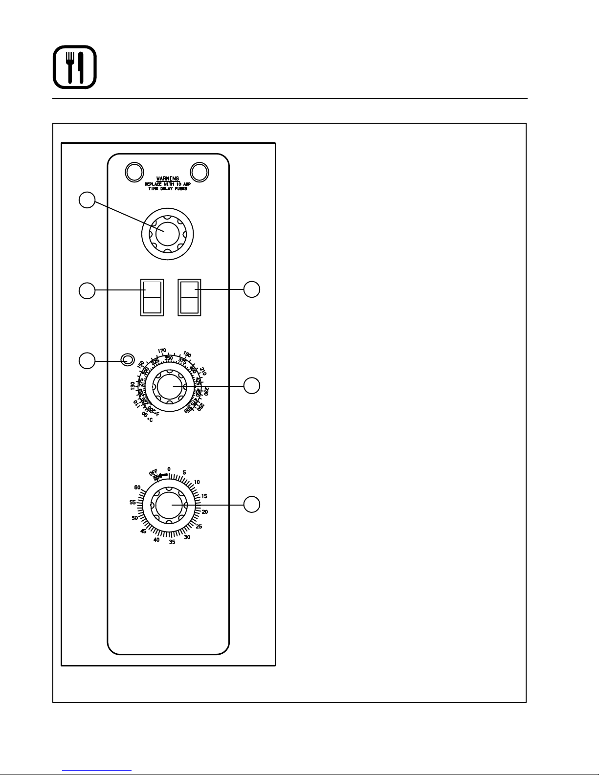
Operation
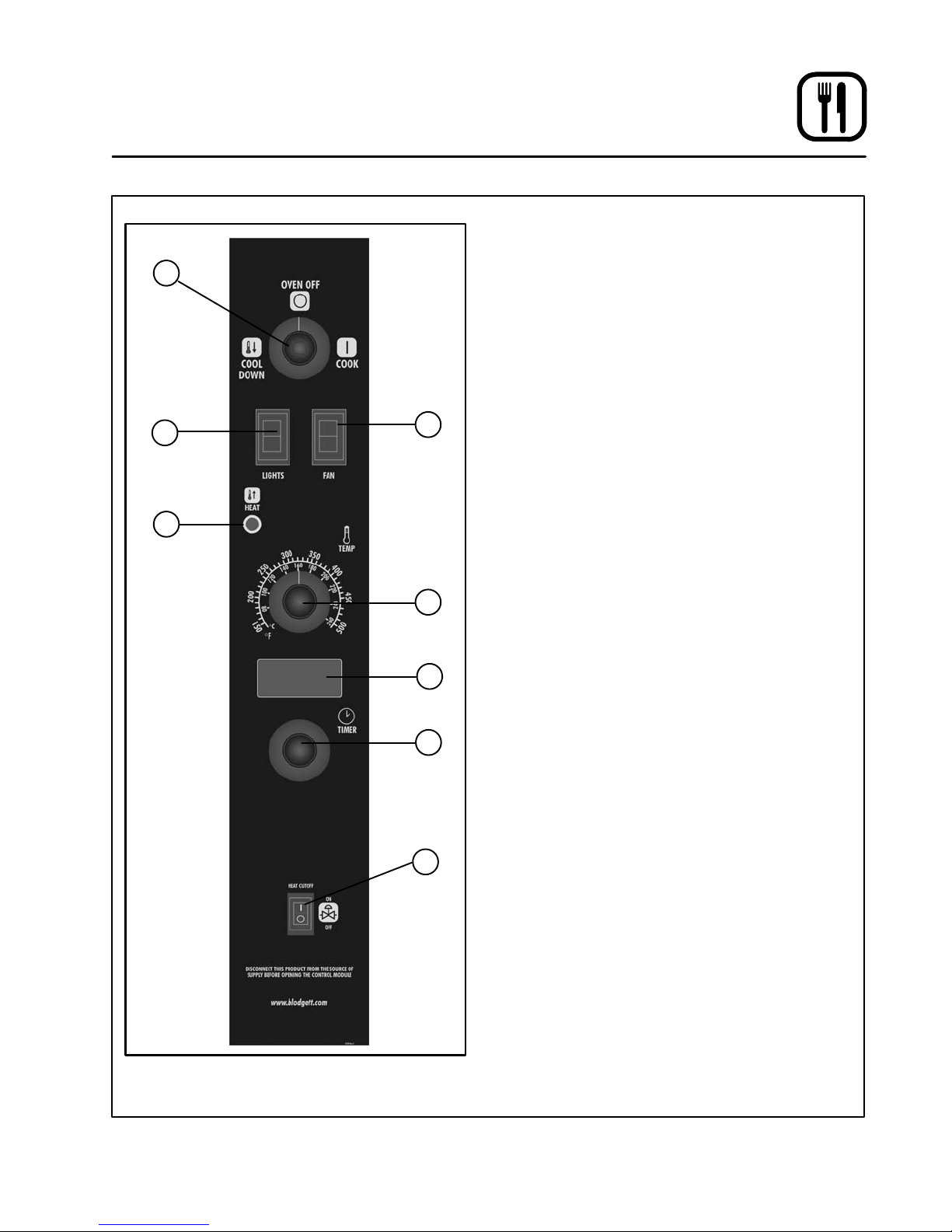
Solid State Manual Control
1
3
4
COOL
DOWN
LIGHT OFF
OVEN READY
OVEN OFF
ON
OFF
LIGHTS
SOLID STATE
THERMOSTAT
COOK
HI
LO
BLOWER
CONTROL DESCRIPTION
1. SELECTOR SWITCH - controls power to the
oven for cook or cool down.
2. BLOWER SWITCH - controls blower speed,
either hi or lo.
3. LIGHTS SWITCH Ć controls interior lights.
4. OVEN READY LIGHT - when lit indicates eleĆ
ments are heating. When the light goes out
the oven has reached operating temperature.
5. SOLID STATE THERMOSTAT Ć allows either 8
preĆset temperatures to be selected in accorĆ
dance with customer requirements, or an infiĆ
2
nite selection of temperatures from 200Ć500_F
(95Ć260_C). (infinite control shown)
6. TIMER - activates an electric buzzer that
sounds when the cook time expires.
OPERATION
1. Turn the SELECTOR Switch (1) to COOK. The
blower and control compartment cooling fan
5
operate and are controlled automatically by
the action of the doors.
2. Set BLOWER Switch (2) to the desired speed.
3. Set the SOLID STATE THERMOSTAT (5) to the
desired setting or temperature.
4. Preheat until the OVEN READY LIGHT (4)
goes out.
5. Load product into the oven. Determine cook
time and set the TIMER (6).
6. When the buzzer sounds, remove the product
6
from the oven. Turn the TIMER knob (6) to OFF
to silence the buzzer.
7. Turn the SELECTOR Switch (1) to OVEN OFF.
TIMER
Figure 10
12
Page 17
Operation
Solid State Manual Control with Digital Timer
CONTROL DESCRIPTION
1. SELECTOR SWITCH - controls power to the
1
3
4
2
5
6
7
8
oven for cook or cool down.
2. BLOWER SWITCH - controls blower speed, eiĆ
ther hi or lo.
3. LIGHTS SWITCH - controls interior lights.
4. OVEN READY LIGHT - when lit indicates
burner operation. When the light goes out the
oven has reached operating temperature.
5. SOLID STATE THERMOSTAT - allows an infiĆ
nite selection of temperatures from 150Ć500_F
(66Ć260_C).
6. DISPLAY - displays cook time
7. TIMER DIAL - used to enter desired cook
time
8. HEAT CUTOFF - circuit breaker
OPERATION
1. Turn the SELECTOR Switch (1) to COOK. The
blower and control compartment cooling fan
operate and are controlled automatically by
the action of the doors. The display reads
00:00.
2. Set BLOWER Switch (2) to the desired speed.
3. Set the SOLID STATE THERMOSTAT (5) to the
desired temperature.
4. Preheat until the OVEN READY LIGHT (4)
goes out.
5. Load product into the oven. Rotate the dial (7)
to the desired time. The timer will begin to
countdown after approximately 1 second.
6. When the buzzer sounds, remove the product
from the oven. Turn the TIMER dial (7) to siĆ
lence the buzzer.
7. Turn the SELECTOR Switch (1) to OVEN OFF.
Figure 11
13
Page 18
Operation
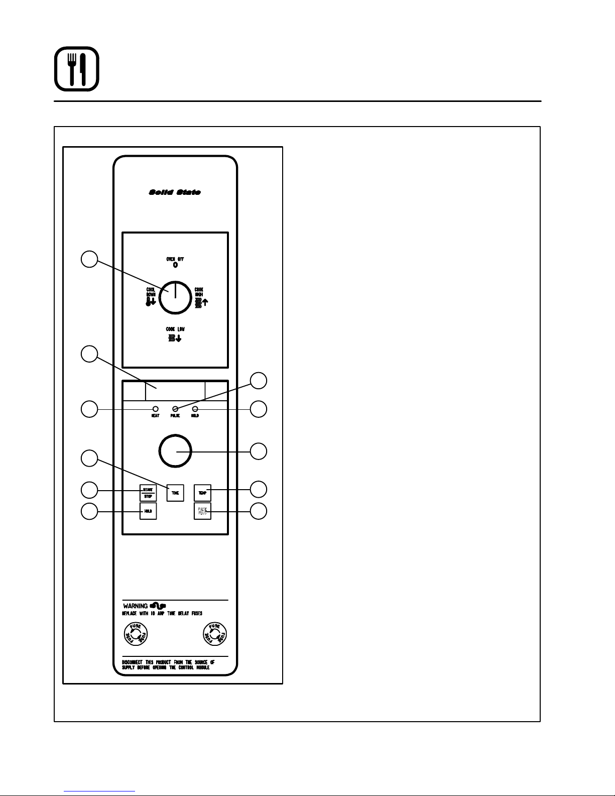
Solid State Digital Control
1
2
3
CONTROL DESCRIPTION
1. SELECTOR SWITCH - turns power to the
oven on or off. Allows selection of Cook or
Cool Down Modes and fan speed (if applicaĆ
ble).
2. DISPLAY - displays time or temperature and
other information related to oven function.
3. HEAT LAMP - lights when heater is on.
4. PULSE LAMP - lights when Pulsed Fan Mode
is turned on.
5. HOLD LAMP - lights when Hold Mode is
turned on.
6. DIAL - used to enter set points in display
7. START/STOP KEY - starts or stops the timer.
8. TIME KEY - used to show time in the display.
9. TEMP KEY - used to show set temperature in
the display.
NOTE: Actual temperature is shown while the
4
10. HOLD KEY - turns Hold Mode on or off.
5
11. PULSE KEY - turns Pulse Mode on or off.
TEMP key is held down.
8
7
10
Figure 12
6
9
11
PROGRAMMING
To set the cook temperature:
1. Press TEMP (9) key.
2. Rotate dial (6) to enter temperature.
To set the cook time:
1. Press TIME (8) key.
2. Rotate the dial (6) to enter time.
NOTE: Time is entered in hours : minutes or
minutes : seconds.
To set the hold time:
1. Press HOLD key (10) to turn hold mode on.
NOTE: HOLD light is on.
2. Rotate dial (6) to enter the hold temperature.
3. Press START/STOP key (7)
To set the pulse time:
1. Press PULSE KEY (11) to turn pulse mode on.
NOTE: Pulse light is on.
2. Rotate DIAL (6) to enter the pulse time. Pulse
time is a portion of the preĆset cook time.
14
Page 19

Operation
Solid State Digital Control
OPERATION
Cook Only:
1. Turn SELECTOR switch (1) to the desired poĆ
sition.
2. Enter the cook time and temperature.
3. Load product into oven.
NOTE: The display reads LOAD with the oven
is near the set temperature.
4. Press the START/STOP key (7). The timer beĆ
gins to count down.
5. When the cook timer reaches 00:00 the buzzĆ
er sounds and the display reads DONE.
6. Press the START/STOP key (7) to silence the
buzzer.
7. Remove the product.
Cook with Hold:
NOTE: HOLD light is on when hold mode is on
and off when hold mode is off.
1. Turn SELECTOR switch (1) to the desired poĆ
sition.
2. Enter the cook time and temperature.
3. Press the HOLD key (10). Enter the hold temĆ
perature.
4. Load product into oven.
NOTE: The display reads LOAD with the oven
is near the set temperature.
5. Push the START/STOP (7) key. Timer begins
to count down.
6. When the cook timer reaches 00:00 the buzzĆ
er sounds and the display reads DONE. The
buzzer turns off after a few seconds. The disĆ
play reads HOLD until the oven reaches the
hold temperature. Then the timer begins to
count up.
7. Push the START/STOP key (7) to stop timer.
8. Remove the product.
9. Push HOLD (10) key to turn off hold mode.
Cook with Pulse:
NOTE: PULSE light is on when pulse mode is on
and off when pulse mode is off.
1. Turn the SELECTOR SWITCH (1) to the deĆ
sired position.
2. Enter cook time and cook temperature.
3. Press PULSE KEY (11). Enter the pulse time.
NOTE: Pulse time is a portion of the cook time
and does not increase the previously
entered cook time.
4. Load product into oven.
NOTE: The display reads LOAD with the oven
is near the set temperature.
5. Push START/STOP KEY (7). The timer begins
to count down the cook time. The oven will be
in pulse mode for the set pulse time. Once the
set time has expired, the unit will automatically
switch to cook mode and continue counting
down.
6. When the cook timer reaches 00:00 the buzzĆ
er sounds and the display reads DONE.
7. Push the START/STOP KEY (7) to turn the
buzzer off.
8. Remove the product.
15
Page 20
Operation
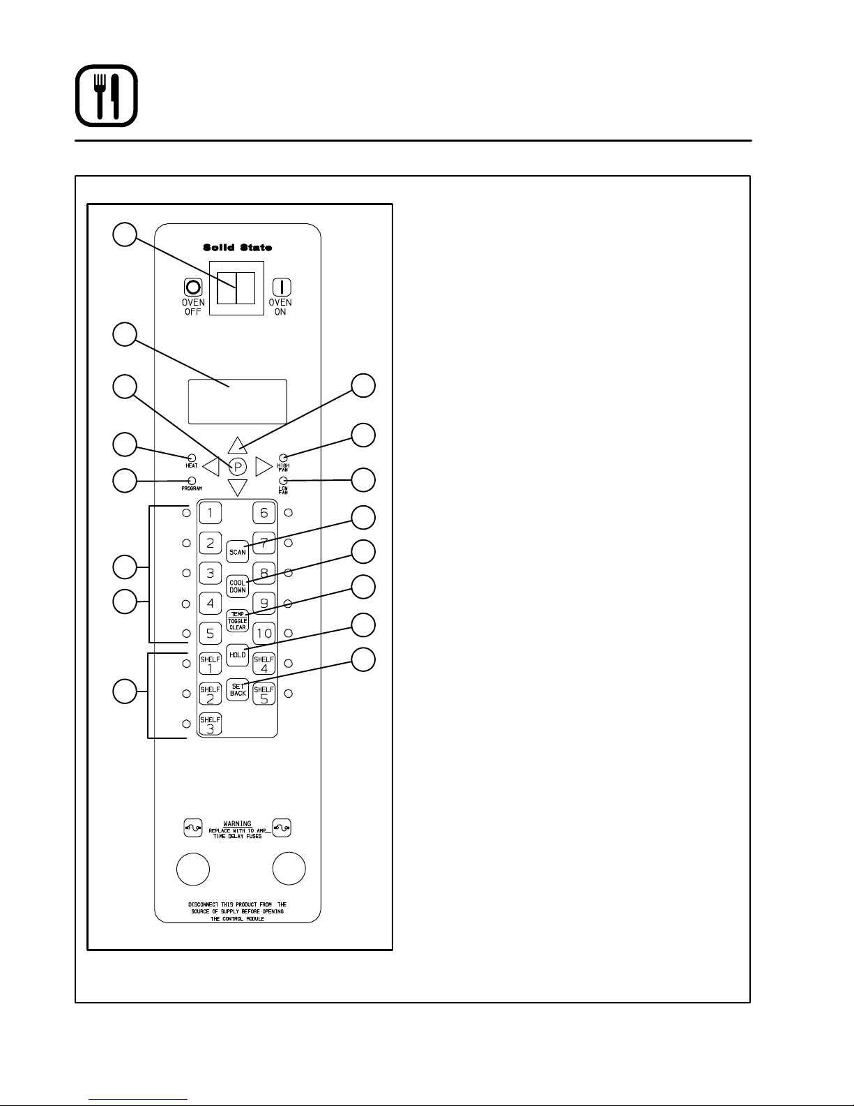
Blodgett IQ2T Vision Control
1
2
3
5
6
14
15
16
10
11
12
13
COMPONENT DESCRIPTION
1. OVEN POWER SWITCH - controls power to
the oven.
2. DISPLAY - displays temperature and other
controller related information.
3. PROGRAM KEY - press to enter the programĆ
ming mode.
4. PROGRAM ARROW KEYS - use to move
through programming menus and options
5. HEAT LED - when lit indicates the control is
4
7
8
9
calling for heat.
6. PROG LED - when lit indicates the controller
is in the programming mode.
7. HIGH FAN LED - when lit indicates the fan is
running at high speed.
8. LOW FAN LED - when lit indicates the fan is
running at low speed.
9. SCAN KEY - Press to view time remaining on
multiple cook cycles and to review recipe proĆ
gramming.
10. COOL DOWN KEY - press to enter the cool
down mode.
11. TEMP/TOGGLE/CLEAR KEY - press during
programming to toggle options.
12. HOLD KEY - press to enter hold mode.
13. SET BACK KEY -
14. PRODUCT KEYS (1Ć10) - assigns a key to a
programmed recipe and begins a proĆ
grammed cooking process. Also used to enĆ
ter numeric values in the programming mode.
15. PRODUCT LEDS - when lit indicate which
product keys are currently in use or proĆ
grammed for the current oven temperature
and fan speed.
16. SHELF KEYS (1Ć5) - assigns a shelf key.
Figure 13
16
Page 21

Operation
Blodgett IQ2T Vision Control
OVEN OPERATION
Oven Startup:
1. Toggle the POWER SWITCH (1) to ON. The
display gives the software revision level. The
oven preheats to the lowest programmed first
stage temperature. The LEDS (15) for all prodĆ
ucts with the same first stage temperature
light.
Single Product Cooking Procedure:
NOTE: If the led next to the desired product key is
lit skip step 1.
1. Press the desired PRODUCT KEY (14). The
oven preheats to the first stage temperature for
the selected product. When the oven reaches
10_ of the preheat temperature an alarm
sounds and the DISPLAY (2) read:
LOAD
2. Load the product into the oven. Press the deĆ
sired PRODUCT KEY (14).
If the shelf timing function is toggled to the
on position for that product key, the DISĆ
PLAY (2) reads:
PICK SHLF
Press a SHELF KEY (16) to assign the product
to that shelf and start the cook cycle. Within
five seconds, the DISPLAY (2) scrolls the prodĆ
uct name and shelf number and counts down
the remaining cook time.
If the shelf timing function is toggled to the
off position for that product, pressing the
product key will start the cook cycle. The DISĆ
PLAY (2) scrolls the product name and counts
down the remaining cook time.
NOTE: If the selected product has a cook time
of greater than 59:59 the DISPLAY (2)
switches to hours:minutes.
NOTE: If the selected product is a single stage
recipe the LEDS for all single stage
products with the same cook temperaĆ
ture and fan speed will light. If the seĆ
lected product is a multiple stage recĆ
ipe no other product LEDS will light.
NOTE: Press and hold the selected product
key for three seconds to cancel the
cook cycle for normal operation. To
cancel the cook cycle when using
shelf timing, press and hold the correĆ
sponding SHELF KEY (16) for 3 secĆ
onds.
3. When the cook time expires an alarm sounds
and the DISPLAY (2) reads:
DONE
Product name
4. Press the selected product key to silence the
alarm. Remove the product. If shelf timing is
used, press the flashing SHELF KEY (16) to siĆ
lence the alarm.
Multiple Batch Cooking Procedure:
This procedure is for single stage recipes with the
same cook temperature and fan speed only.
NOTE: If the led next to the first desired product
key is lit skip step 1.
1. Press the first desired PRODUCT KEY (14).
The LEDS for all recipes with the same cook
temperature and fan speed will light.
The oven preheats to the cook temperature for
the selected product. When the oven reaches
10_ of the preheat temperature an alarm
sounds and the DISPLAY (2) reads:
LOAD
17
Page 22

Operation
Blodgett IQ2T Vision Control
2. Load the product into the oven. Press the deĆ
sired PRODUCT KEY (14).
If the shelf timing function is toggled to the
on position for that product key, the DISĆ
PLAY (2) reads
PICK SHLF
Press a SHELF KEY (16) to assign the product
to that shelf and start the cook cycle. Within
five seconds, the DISPLAY (2) scrolls the prodĆ
uct name and shelf number and counts down
the remaining cook time.
If the shelf timing function is toggled to the
off position for that product, pressing the
product key will start the cook cycle. The DISĆ
PLAY (2) scrolls the product name and counts
down the remaining cook time.
3. Load the second product. Press the desired
PRODUCT KEY (14). the DISPLAY (2) reads
PICK SHLF
Press a SHELF KEY (16) to assign the product
to that shelf and start the cook cycle for prodĆ
uct two.
NOTE: Only products with lighted LEDS may
be selected.
Repeat step 3 for additional products.
4. The DISPLAY (2) scrolls the product name and
counts down the remaining cook time for the
product with the least time remaining.
NOTE: To view the remaining cook time for
the other products press and hold the
SCAN KEY (9). The display cycles
through the remaining cook times for
each product. Only the led for the
product with the cook time displayed
will be lit.
5. When a cook time expires an alarm sounds.
The display reads
DONE
The led for the finished product lights. All other
LEDS are dark.
6. Press the SHELF KEY (16) for the finished
product to silence the alarm. Remove the
product. Close the oven door. The DISPLAY
(2) scrolls the product name and counts down
the remaining cook time for the product with
the least time remaining.
7. When the cook time expires an alarm sounds
and the display reads:
DONE
8. Press the SHELF KEY (16) to silence the
alarm. Remove the product.
Oven Cool Down:
1. Close the oven door. Press the COOL DOWN
KEY (10).
NOTE: Cool down cannot be activated with the
oven door open. Once the cool down cycle
has begun the doors may be opened to
speed the cooling process.
To Review Repipe Programming:
1. Press the SCAN KEY (9). The display read:
RECIPE REVIEW
Select Product
The LEDs (15) for all previously programmed
product keys light. Press the PRODUCT KEY
(14) you wish to review. The display gives the
recipe cook time for stage 1. Use the PROĆ
GRAM ARROW KEYS (4) to scroll through the
recipe programming for the selected product
key.
2. The control will exit recipe review after 30 secĆ
onds if no key is pressed.
18
Page 23

Operation
Blodgett IQ2T Vision Control
PRODUCT KEY PROGRAMMING
To enter the product programming mode
1. Press and hold the PROGRAM KEY (3). The
DISPLAY (2) reads:
Prod Cnt
Programming
Use the PROGRAM ARROW KEYS (4) to highĆ
light Programming. Press the PROGRAM KEY
(3) to select. The display reads:
ENTER CODE
Use the PRODUCT KEYS (14) to enter the proĆ
gramming access code 1724. Press the PROĆ
GRAM KEY (3). The display reads:
RECIPE
Press the PROGRAM KEY (3). All of the prodĆ
uct LEDSs will light and the display reads:
Select Product
To Program
To program the product
4. The display reads:
Shelf Cook
XXX
Definition: Shelf cook enables the operĆ
ator to reference product to one of the
five shelf positions in the oven. At the
end of a shelf cooking cycle the oven
will display the name of the product and
the shelf number that is ready to be
pulled. Shelf cooking is not available
for multiĆstage recipes.
Use non shelf cooking when you do not
need to reference product to one of the
five shelf positions in the oven. Non
shelf cooking may be used for single
stage recipes and MUST be used for
multiĆstage recipes.
Use the PROGRAM ARROW KEYS (4) to seĆ
lect either YES (for shelf cooking) or NO (for
non shelf cooking). Press the PROGRAM KEY
(3).
To select the product to program
2. Press the desired product key. The display
reads:
All
Name
With All highlighted, press the PROGRAM
KEY (3). The display reads:
Product Name
AAA
The first alphabetical listing in the product
name library appears.
3. To change the product name, use the PROĆ
GRAM ARROW KEYS (4) to scroll through the
product name library. When the desired prodĆ
uct name is highlighted, press the PROGRAM
KEY (3) to select.
5. The display reads:
Stage 1 Time
XX:XX
Use the PRODUCT KEYS (14) to enter the deĆ
sired cook time. Press the PROGRAM KEY (3).
6. The display reads:
Stage 1 Temp
XXXF (or C)
Use the PRODUCT KEYS (14) to enter the deĆ
sired cook temperature. Press the PROGRAM
KEY (3).
19
Page 24

Operation
Blodgett IQ2T Vision Control
7. The display reads:
Stage 1 Timing
XXX
Definition: There are 3 options for timĆ
ing mode when shelf cooking: Straight,
Flex and Sensitivity. Straight has no
time adjustment. Flex adjusts the cook
time to compensate for any difference
between the setpoint and actual temĆ
perature. Sensitivity enables a product
key to have a flex adjustment for each
of the five shelves. Sensitivity values are
set in the manager level programming.
NOTE: Sensitivity is only available when usĆ
ing shelf cooking.
Use the PROGRAM ARROW KEYS (4) to seĆ
lect the desired timing mode. Press the PROĆ
GRAM KEY (3).
8. The display reads:
Stage 1 Fan Spd
XX
Use the PROGRAM ARROW KEYS (4) to seĆ
lect either HIGH or LOW fan speed. Press the
PROGRAM KEY (3).
9. The display reads:
Stage 1 Fan On
XX:XX
Use the PRODUCT KEYS (14) to enter the deĆ
sired length of the time the fan should be on
in the pulse cycle. Press PROGRAM KEY (3).
The display reads:
Stage 1 Fan OFF
XX:XX
Use the PRODUCT KEYS (14) to enter the deĆ
sired length of the time the fan should be off
in the pulse cycle. Press the PROGRAM KEY
(3).
10. If you are programming a product using shelf
cooking skip to step 11.
If you are programming a product that does
not use shelf cooking the display reads:
Stage 2 Time
XX:XX
Repeat steps 5 through 10 for each remaining
stage. If you are programming a single stage
recipe without shelf cooking enter at time of
00:00 for stage 2.
11. The display reads:
Alarm 1 Time
XX:XX
Stage 1 Fan Cyc
XXX
Definition: There are 3 options for fan
cycle time: Pulse, Heat and Full. Pulse
allows the fan to turn on and off as proĆ
grammed. Heat allows the fan to operĆ
ate with heat only. Full provides continuĆ
ous fan operation when door is closed.
Use the PROGRAM ARROW KEYS (4) to seĆ
lect the fan cycle. If heat or full are selected
skip to step 10. If pulse is selected the display
reads:
Definition: If you would like the alarm to
sound prior to the completion of the
cook cycle you may program it here.
The alarm time counts up from the beĆ
ginning of the cook cycle. For example,
if you want an alarm 9 minutes into the
cook cycle, program the alarm time at
9:00.
Use the PRODUCT KEYS (14) to enter the time
for the first alarm to sound. If 00:00 is entered
for an alarm time, skip to step NO TAG.
Press the PROGRAM KEY (3). If a time other
than 00:00 is entered the display reads:
20
Page 25

Operation
Blodgett IQ2T Vision Control
Alarm 1 Name
XXX
To change the alarm name, use the PROĆ
GRAM ARROW KEYS (4) to scroll through the
alarm name library.
Press the PROGRAM KEY (3). The display
reads:
Alarm 1 Done
XXX
Use the PROGRAM ARROW KEYS (4) to seĆ
lect either AUTOMATIC or MANUAL.
Press the PROGRAM KEY (3). The display
reads:
Alarm 1 Tone
XXX
Use the PROGRAM ARROW KEYS (4) to seĆ
lect either NONE, SHORT, MEDIUM, LONG,
DOUBLE, or LONG/SHORT.
Press the PROGRAM KEY (3). The display
reads:
Alarm 2 TIme
XXX
Repeat step 11 for alarm 2. If no Alarm 2 is deĆ
sired, enter a time of 0.
Use the PRODUCT KEYS (14) to enter desired
hold temperature. The minimum hold temperĆ
ature is 140F. Press the PROGRAM KEY (3).
14. The display reads:
Hold Done
XXX
Use the PROGRAM ARROW KEYS (4) to seĆ
lect either AUTOMATIC or MANUAL. Press the
PROGRAM KEY (3).
15. The display reads:
Hold Fan Speed
XXX
Use the PROGRAM ARROW KEYS (4) to seĆ
lect HIGH or LOW.Press the PROGRAM KEY
(3).
To exit the program mode
16. The display reads:
Exit
All
Use the PROGRAM ARROW KEYS (4) to scroll
down until exit is highlighted. Press the PROĆ
GRAM KEY (3). The display reads:
12. Press the PROGRAM KEY (3). The display
reads:
Hold Time
XX:XX
Use the PRODUCT KEYS (14) to enter desired
hold time. If a hold time of 00:00 is entered skip
to step NO TAG. Press the PROGRAM KEY
(3).
13. The display reads:
Hold Temp
XXXF
Recipe
Exit
To program another product key select recipe.
To exit the progam mode select exit. The disĆ
play reads:
Product Cnt
Programming
Use the PROGRAM ARROW KEYS (4) to scroll
down until exit is highlighed. Press the PROĆ
GRAM KEY (3) to exit the programming mode.
21
Page 26

Operation
Blodgett IQ2T Vision Control
MANAGER LEVEL PROGRAMMING
Entering the manager programming mode
1. Press and hold the PROGRAM KEY (3). The
display reads:
Prod Cnt
Programming
Use the PROGRAM ARROW KEYS (4) to highĆ
light Programming. Press the PROGRAM KEY
(3) to select. The display reads:
ENTER CODE
Use the PRODUCT KEYS (14) to enter the proĆ
gramming access code 6647. Press the PROĆ
GRAM KEY (3). The display reads:
System
ProdName Lib
Programming the MANAGER SYSTEM options
1. With System highlighted, press the PROĆ
GRAM KEY (3) to select. The display reads:
Appliance Type
XXX
3. The display reads:
Tone Volume
XXX
Use the PROGRAM ARROW KEYS (4) to seĆ
lect None, 1, 2, 3 or 4. Press the PROGRAM
KEY (3) to select the desired level for all audiĆ
ble signals.
4. The display reads:
Temperature
XXX
Use the PROGRAM ARROW KEYS (4) to seĆ
lect either F or C. Press the PROGRAM KEY (3)
to select the desired temperature units.
5. The display reads:
Hold Time
XXX
Use the PRODUCT KEYS (14) to enter the
length of hold time for the manual hold button.
Press the PROGRAM KEY (3).
If a time of 00:00 is enter skip to step 6.
If a hold time is entered the display reads:
Hold Temp
XXX
Use the PROGRAM ARROW KEYS (4) to highĆ
light electric half, electric full, XCEL, gas half or
gas full. Press the PROGRAM KEY (3) to select
the correct appliance type.
2. The display reads:
Language
XXX
Use the PROGRAM ARROW KEYS (4) to seĆ
lecteither English or Other. Press the PROĆ
GRAM KEY (3) to select the desired language.
Use the PRODUCT KEYS (14) to enter the hold
temperature for the manual hold button. Press
the PROGRAM KEY (3). The display reads:
Hold Done
XXX
Use the PROGRAM ARROW KEYS (4) to seĆ
lect either AUTOMATIC or MANUAL. Press the
PROGRAM KEY (3). The display reads:
Hold Fan Speed
XXX
Use the PROGRAM ARROW KEYS (4) to seĆ
lect HIGH or LOW. Press the PROGRAM KEY
(3).
22
Page 27

Operation
Blodgett IQ2T Vision Control
6. The display reads:
Setback Time
XXX
Definition - Setback time is an energy
savings feature that automatically lowĆ
ers the cavity temperature when the
oven is idle.
Use the PRODUCT KEYS (14) to enter the
length of the time the oven is idle before enterĆ
ing setback mode. Press the PROGRAM KEY
(3).
If a time of 00:00 is enter skip to step 7.
If a setback time is entered the display reads:
Setback Temp
XXX
Use the PRODUCT KEYS (14) to enter the setĆ
back temperature. Press the PROGRAM KEY
(3).
7. The display reads:
Shelf Sense
XXX
Definition - If you are using sensitivity
as a timing mode for single stage stage
recipes this feature must be turned on.
Use the PROGRAM ARROW KEYS (4) to seĆ
lect either Yes or No. Press the PROGRAM
KEY (3).
If no is selected skip to step 8.
If yes is selected the display reads:
Shelf 1 Sens
XXX
Use the PRODUCT KEYS (14) to enter a sensiĆ
tivity level of 1Ć9 for shelf 1. Press the PROĆ
GRAM KEY (3). Repeat for shelves 2Ć5.
8. The display reads:
Preheat Time
XXX
Definition - This function programs
time for the oven to idle after reaching
the preheat temperature allowing heat
to saturate the oven cavity. The preheat
time only applies to the initial preheat
after a cold start. This is strictly a
prompt, the user may begin a bake
cycle even with the preheat prompt disĆ
played.
Use the PRODUCT KEYS (14) to enter a preĆ
heat time. Press the PROGRAM KEY (3).
23
Page 28

Operation
Blodgett IQ2T Vision Control
Programming the PRODUCT NAME
NOTE: Use these instructions to modify an existĆ
ing name, to add a product name or to deĆ
lete a name already in the library.
NOTE: Names may be up to 16 characters long
and can contain letters and numbers.
1. After entering the manager level programĆ
ming (see page 22) the display reads:
System
ProdName Lib
With ProdName Lib highlighted, press the
PROGRAM KEY (3) to select. The display
reads:
Prod Name Lib
2. Use the up and down PROGRAM ARROW
KEYS (4) to scroll through the existing product
names. Or press the PRODUCT KEY (14) that
corresponds with the first letter of the name
you are looking for. Then use the PROGRAM
ARROW KEYS (4) to scroll to the desired
name.
3. Press the SCAN KEY (9) to edit the name.
4. Use the PRODUCT KEYS (14) to edit the prodĆ
uct name. Press the right arrow key to adĆ
vance to the next character.
To clear the product name, press the TEMP/
TOGGLE/CLEAR KEY (11).
NOTE: Use product key 1 for spaces, periĆ
ods, quotation marks and underlines.
5. Once the product name has been entered,
press the PROGRAM KEY (3). The display
reads:
Save Library
ADD
Use the PROGRAM ARROW KEYS (4) to seĆ
lect either ADD, MODIFY or CANCEL. Select
ADD to create a new product name. Select
MODIFY to change an existing product name.
Select CANCEL to exit the edit mode without
saving your changes.
NOTE: To delete an exsisting product name,
find the name in the product library.
Press the TEMP/TOGGLE/CLEAR KEY
(11) to clear the entire product name.
Then select MODIFY to overwrite the
name with a clear screen.
6. Press the PROGRAM KEY (3) to exit the prodĆ
uct name library.
24
Page 29

Operation
Blodgett IQ2T Vision Control
Programming the ALARM NAME
NOTE: Use these instructions to modify an existĆ
ing name, to add an alarm name or to deĆ
lete a name already in the library.
NOTE: Names may be up to 16 characters long
and can contain letters and numbers.
1. After entering the manager level programĆ
ming (see page 22) the display reads:
System
ProdName Lib
Use the PROGRAM ARROW KEYS (4) to highĆ
light Alarm Lib. Press the PROGRAM KEY (3)
to select. The display reads:
Alarm Name Lib
2. Use the up and down PROGRAM ARROW
KEYS (4) to scroll through the existing alarm
names. Or press the PRODUCT KEY (14) that
corresponds with the first letter of the name
you are looking for. Then use the PROGRAM
ARROW KEYS (4) to scroll to the desired
name.
3. Press the SCAN KEY (9) to edit the name.
4. Use the PRODUCT KEYS (14) to edit the alarm
name. Press the right arrow key to advance to
the next character.
To clear the alarm name, press the TEMP/
TOGGLE/CLEAR KEY (11).
NOTE: Use product key 1 for spaces, periĆ
ods, quotation marks and underlines.
5. Once the alarm name has been entered,
press the PROGRAM KEY (3). The display
reads:
Save Library
ADD
Use the PROGRAM ARROW KEYS (4) to seĆ
lect either ADD, MODIFY or CANCEL. Select
ADD to create a new alarm name. Select
MODIFY to change an existing alarm name.
Select CANCEL to exit the edit mode without
saving your changes.
NOTE: To delete an exsisting alarm name,
find the name in the product library.
Press the TEMP/TOGGLE/CLEAR KEY
(11) to clear the entire alarm name.
Then select MODIFY to overwrite the
name with a clear screen.
6. Press the PROGRAM KEY (3) to exit the alarm
name library.
Exiting the manager program mode
1. The display reads:
System
ProdName Lib
Use the PROGRAM ARROW KEYS (4) to scroll
up until Exit is highlighted. Press the PROĆ
GRAM KEY (3). The display reads:
Prod Cnt
Programming
Use the PROGRAM ARROW KEYS (4) to scroll
up until Exit is highlighted. Press the PROĆ
GRAM KEY (3) to exit the programming mode.
25
Page 30

Operation
How Cook and Hold Works
With the optional COOK & HOLD feature, meat is
roasted at lower temperatures for longer periods
of time. This preserves flavor and tenderness and
prevents over drying. There are three phases in
cook and hold roasting.
D Primary Cooking - controlled by the COOK &
HOLD TIMER. The meat is cooked at a low temĆ
perature until approximately 2/3 done.
D Cooking from Stored Heat - when the primaĆ
ry cook time expires, the oven automatically
switches to HOLD. The product continues to
cook from the heat stored in the oven. Meat
must remain in the hold cycle for a minimum of
1Ć1/2 to 2 hours before being served.
D Hold - holds the product for several hours beĆ
fore serving without loss of moisture or tenderĆ
ness.
All meat should be completely thawed by refrigerĆ
ation. Using frozen meat increases the cook time
causing shrinkage.
Product Cook
Prime rib, bone cap off
14Ć18 lbs. (6.4Ć8.1 kg)
Te mp .
200_F
93_C
Hold
Te mp .
140_F
60_C
250_
225_
200_
175_
150_
125_
100_
Temperature (F)
75_
50_
25_
Oven temp.
Meat temp
Quantity Cook Time
(Hrs)
1
3
6
3
3Ć1/4
3Ć1/2
Oven switches from
cook to hold
Stored heat
Product may be
held up to 16 hours
Product may be
removed and
served
345612 789
Time (hours)
Figure 14
Min. Hold
Time (Hrs)
1
1Ć1/2
2
Total Time
(Hrs)
4
4Ć3/4
5Ć1/2
Prime rib, bone cap on
14Ć18 lbs. (6.4Ć8.1 kg)
Top or bottom rounds
20Ć22 lbs. (9.1Ć10.0 kg)
Pork roast or ham
10Ć12 lbs. (4.5Ć5.4 kg)
Turkey
20Ć22 lbs. (9.1Ć10.0 kg)
Leg of Lamb, bone in
8Ć10 lbs. (4.36Ć4.5 kg)
200_F
93_C
200_F
93_C
250_F
121_C
250_F
121_C
225_F
107_C
140_F
60_C
140_F
60_C
170_F
76_C
170_F
76_C
160_F
71_C
26
1
3
6
1
3
6
2
4
6
1
6
2
4
6
3Ć1/2
4
4Ć1/2
3Ć1/2
4
4Ć1/2
4
4Ć1/4
4Ć1/2
3Ć1/4
4
2Ć1/2
2Ć3/4
3
1
1Ć1/2
2
1
1Ć1/2
2
1
1Ć1/2
2
1
1Ć1/2
1
1Ć1/2
2
4Ć1/2
5Ć1/2
6Ć1/2
4Ć1/2
5Ć1/2
6Ć1/2
5
5Ć3/4
6Ć1/2
4Ć3/4
5Ć1/2
3Ć1/2
4Ć1/4
5
Page 31

Operation
General Guidelines for Operating Personnel
COOK TIMES AND TEMPERATURES
Preheating the oven
Always preheat the oven before baking or roastĆ
ing. We recommend preheating 50_F (28_C)
above the cook temperature to offset the drop in
temperature when the doors are opened and cold
product is loaded into the oven. Set the thermostat
to the cook temperature after the product is
loaded.
NOTE: For frozen product, preheat the oven
100_F (56_C) above the cook temperaĆ
ture.
Cook Temperatures
Generally, cook temperatures should be 50_F
(28_C) lower than deck or range oven recipes. If
the edges of the product are done but the center
is raw, or if there is color variation, reduce the therĆ
mostat setting another 15Ć25_F (10Ć15_C). ConĆ
tinue to reduce the cook temperature on succesĆ
sive loads until the desired results are achieved.
NOTE: Cooking at excessive temperatures will
not reduce cook time, it will produce unĆ
satisfactory baking and roasting results.
Cook Time
Check the product in about half the time recomĆ
mended for deck or range oven recipes. Record
times and temperatures which provide best reĆ
sults for future reference.
NOTE: Cook time will vary with the amount of
product loaded, the type of pan and the
temperature.
OPERATING TIPS
Pans and Racks
Product or pan height determines how many
racks are used. The oven holds up to 10 18" x 26"
(45.7 x 66.0 cm) bun pans.
Load the oven from the bottom, centering the pans
on the rack. Never place a pan or aluminum foil on
the bottom of the oven. This obstructs the flow of
air and results in uneven baking and roasting.
Roasting
To reduce shrinkage when roasting, place meat
directly on the racks. Place a sheet pan oneĆhalf
full of water in the bottom rack position. The water
evaporates, increasing humidity in the oven
chamber. The pan catches grease from the meat,
making oven cleaning easier.
Baking
Weigh the product to ensure equal distribution in
each pan. Varying amounts of product will cause
uneven baking results.
Fans
The fan must be operating for the oven to heat.
Use the Pulse Plus feature to allow light or liquid
product to set in the pan and to avoid rippling toĆ
wards the fan. If your oven is not equipped with
this feature use the following procedure.
1. Preheat the oven 25_F (15_C) above the bakĆ
ing temperature.
2. Load the oven with product. Close the doors.
3. Set the thermostat to the baking temperature.
4. Turn the oven off.
5. Allow the product to set for 5-7 minutes with
the fan off. The residual heat in the oven sets
the product.
6. Turn the oven on for the remainder of the bake.
Lights
Turn the oven lights off when not viewing the prodĆ
uct. Leaving the lights on for extended periods of
time shortens the bulb life considerably.
27
Page 32

Operation
Suggested Times and Temperatures
Product Temperature Time # Shelves
Meats
Hamburger Patties (5 per lb)
Steamship Round (80 lb. quartered)
Standing Rib Choice (20 lbs, trimmed, rare)
Banquet Shell Steaks (10 oz. meat)
Swiss Steak after Braising
Baked Stuffed Pork Chop
Boned Veal Roast (15 lbs.)
Lamb Chops (small loin)
Bacon (on racks in 18" x 26" pans)
Poultry
Chicken Breast & Thigh
Chicken Back & Wing
Chicken (21/2 lbs. quartered)
Turkey Rolled (18 lb. rolls)
Fish and Seafood
Halibut Steaks, Cod Fish (frozen 5 oz)
Baked Stuffed Lobster (21/2 lb.)
Lobster Tails (frozen)
400_F (205_C)
275_F (135_C)
235_F (115_C)
450_F (235_C)
275_F (135_C)
375_F (190_C)
300_F (150_C)
400_F (205_C)
400_F (205_C)
350_F (175_C)
350_F (175_C)
350_F (175_C)
310_F (155_C)
350_F (175_C)
400_F (205_C)
425_F (220_C)
8Ć10 mins.
2 hrs 45 mins.
2 hrs 45 mins.
7Ć8 mins.
1 hr.
25Ć30 mins.
3 hrs. 10 mins.
7Ć8 mins.
5Ć7 mins.
40 mins.
35 mins.
30 mins.
3 hrs 45 mins.
20 mins.
10 mins.
9 mins.
10
2
2
5
5
5
2
5
10
5
5
5
3
5
3
5
Cheese
Macaroni & Cheese Casserole
Melted Cheese Sandwiches
Potatoes
Idaho Potatoes (120 ct.)
Oven Roasted Potatoes (sliced or diced)
Baked Goods
Frozen Berry Pies (22 oz)
Fresh Apple Pie (20 oz.)
Pumpkin Pies (32 oz.)
Fruit Crisp
Bread (24 Ć 1 lb. loaves)
Southern Corn Bread
Baking Soda Biscuits
Brown & Serve Rolls
Sheet Cakes (5 lb. mixed batter per pan)
Chocolate Cake
Brownies
NOTE: Actual times and temperatures may vary considerably from those shown above. They are affected
by weight of load, temperature of the product, recipe, type of pan and calibration of thermostat.
Should your recipe vary, write in your proven time and temperature for ready reference.
350_F (175_C)
400_F (205_C)
400_F (205_C)
325_F (165_C)
325_F (150_C)
350_F (175_C)
300_F (150_C)
300_F (150_C)
325_F (155_C)
375_F (190_C)
400_F (205_C)
350_F (175_C)
325_F (160_C)
325_F (160_C)
325_F (150_C)
30 mins.
8 mins.
50 mins.
10 mins.
35 mins.
25Ć30 mins.
30Ć50 mins.
25 mins.
30 mins.
15Ć20 mins.
6 mins.
15 mins.
16Ć18 mins.
20 mins.
15 mins.
5
10
5
5
5 (30 pies)
5 (30 pies)
5 (20 pies)
5
3
5
5
5
5
5
5
28
Page 33

Maintenance
Cleaning and Preventative Maintenance
CLEANING THE OVEN
Painted and stainless steel ovens may be kept
clean and in good condition with a light oil.
1. Saturate a cloth, and wipe the oven when it is
cold.
2. Dry the oven with a clean cloth.
On the stainless front or interiors, deposits of
baked on splatter may be removed with any nonĆ
toxic industrial stainless steel cleaner. Heat tint
and heavy discoloration may be removed with any
nonĆtoxic commercial oven cleaner.
1. Apply cleaners when the oven is cold. Always
rub with the grain of the metal.
The porcelain interior can be cleaned with any
commercial oven cleaner. Be sure caustic cleanĆ
ing compounds DO NOT come in contact with the
blower wheel and the aluminized steel panel diĆ
rectly behind it.
1. Remove the racks, rack supports and blower
wheel from the oven.
2. Soak the parts in a solution of ammonia and
water.
3. Reinstall after cleaning.
NOTE: If the oven is moved the restraint must be
reconnected after the unit is returned to it's
regular position.
PREVENTATIVE MAINTENANCE
The best preventative maintenance measures are,
the proper installation of the equipment and a proĆ
gram for routinely cleaning the ovens.
Annual Maintenance
This oven requires no lubrication, however, the
venting system should be checked annually for
possible deterioration resulting from moisture and
corrosive flue products.
If maintenance or repairs are required, contact
your local Blodgett service company, a factory
representative or the Blodgett Oven company.
WARNING!!
Always disconnect the appliance from the
power supply before servicing or cleanĆ
ing.
29
Page 34

Maintenance
Troubleshooting Guide
POSSIBLE CAUSE(S) SUGGESTED REMEDY
SYMPTOM: Heating elements do not come on.
S Oven not plugged in.
S Power switch on the control panel is off.
S Control set below ambient temperature.
S Doors are open.
S Computerized controls - error code on display.
SYMPTOM: Oven does not come to ready.
S The oven has not reached preheat temperature.
S Fan delay feature may be activated, if applicable.
S Internal problem with main temperature control.
SYMPTOM: Convection fan does not run.
S Oven is not plugged in.
S Oven is not set to the cook mode.
S Circuit breaker tripped.
S Fan delay feature may be activated, if applicable.
S Doors are open
SYMPTOM: General baking problems.
S Plug in electrical supply cord.
S Set the control panel to COOK or OVEN ON.
S Set to desired cook temperature.
S Close doors.
S *
S Wait for oven to reach preheat temperature.
S Deactivate fan delay feature.
S *
S Plug in electrical supply cord.
S Set the control panel to COOK or OVEN ON.
S Reset the breaker.
S Deactivate fan delay feature.
S Close doors.
S Computerized controls - incorrect product
programming.
S Thermostat out of calibration.
*Denotes remedy is a difficult operation and should be performed by qualified personnel only. It is recommended, however, that
All repairs and/or adjustments be done by your local Blodgett service agency and not by the owner/operator. Blodgett cannot asĆ
sume responsibility for damage as a result of servicing done by unqualified personnel.
WARNING!!
Always disconnect the power supply before cleaning or servicing the oven.
S Reprogram control per Operation section.
S *
30
Page 35

La cuisson dans un four à convection diffère de la
q
q
cuisson dans un four de cuisine ordinaire en ce
sens que de l'air chaud circule en permanence auĆ
tour de l'aliment cuit, sous l'effet d'un ventilateur
enfermé dans une enceinte spéciale. Le mouveĆ
ment continu de l'air, en éliminant constamment la
couche d'air froid qui se formerait autrement auĆ
tour de l'aliment, permet la pénétration plus rapide
de la chaleur. Il en résulte un aliment de qualité
comparable à ceux préparés dans un four ordinaiĆ
re, mais cuit à température inférieure et en moins
de temps.
Le four à convection représente ce qu'il y a de plus
perfectionné en termes de rendement énergétiĆ
que, de fiabilité et de facilité d'emploi. Comme la
source thermique se trouve à l'intérieur même de
la chambre de cuisson, d'importantes économies
d'énergie peuvent être réalisées en même temps
que d'excellents résultats de cuisson.
Introduction
Description et Spécifications du Four
Circulation de l'air dans les fours à convection
Figure 1
SPÉCIFICATIONS ÉLECTRIQUES (par section de four)
KW Fréqu Tension Phase
ence
Installation ÉĆU et Canadar
11.0 60 208 1 51 - 51 - 6 AWG
11.0 60 208 3 31 29 29 - 8 AWG
11.0 60 220Ć240 1 44 - 44 - 6 AWG
11.0 60 220Ć240 3 26 24 24 - 8 AWG
11.0 60 440 3 15 14 14 - 12 AWG
11.0 60 480 3 14 13 13 - 12 AWG
Installation à l'export
11.0 50 208 3 18 18 18 4 Calibre suivant code local
11.0 50 220Ć240 1 48 - - 48 Calibre suivant code local
11.0 50 220/380 3 18 16 16 2 Calibre suivant code local
11.0 50 240/415 3 18 14 14 4 Calibre suivant code local
11.0 50 230/400 3 18 15 15 3 Calibre suivant code local
Ampères
L1 L2 L3 N
Connexion électrique
(calibre minimum)
31
Page 36

Introduction
Éléments du Four
Éléments chauffants - situés sur la paroi arrière
du four, les éléments procurent de la chaleur à la
chambre de cuisson des fours électriques.
Chaîne et Tendeur - contrôlent le fonctionneĆ
ment des portes de four.
Panneau de Contrôle - contient les câblages et
les éléments permettant de contrôler le fonctionĆ
nement du four.
Grilles de four - cinq grilles sont fournies en
équipement standard. Des grilles supplémentaiĆ
res sont disponibles.
Éléments
chauffants
Ventilateur
Support de Grille - tient les grilles en place.
Couvercle de Ventilateur - situé sur la paroi intéĆ
rieur au fond du four. Protège le ventilateur.
Ventilateur - tourne pour faire circuler l'air chaud
dans le four.
Moteur à Convection - fournit la force pour faire
tourner le ventilateur.
Éclairage du Four - fournit l'éclairage à l'intéĆ
rieur du four.
Moteur à
Convection
Couvercle de
Ventilateur
Support de
Grille
Grilles de four
Chaîne et
Tendeur
Éclairage du
Four
Figure 2
32
Panneau de
Contrôle
Couvercle du panneau
de commande
Page 37

Installation
Livraison et Implantation
LIVRAISON ET INSPECTION
Tous les fours sont expédiés en conteneurs. A la
réception de votre four Blodgett vous devez:
D Vérifier que les emballages ne sont pas abimés.
Toute défection dans l'emballage doit être noĆ
tée sur l'accusé de reception de la marchandiĆ
se; celuiĆci doit être signé par le chauffeur.
D Sortir le four de son emballage et vérifier son
bon état. Les transporteurs n'acceptent les réĆ
clamations et plaintes que si elles sont faites
dans les quinze jours qui suivent la livraison et
si l'emballage a été conservé afin d'être
inspecté.
La Blodgett Oven Co., n'est pas responsable
des dégâts subis pendant le transport. Le
transporteur est seul responsable de la livraiĆ
son du matériel en bon état lorsque l'expédiĆ
tion a été acceptée. Néanmoins, nous sommes
à votre disposition pour vous aider à composer
votre dossier de réclamation.
IMPLANTATION DU FOUR
L'implantation correcte et bien étudiée du four
sera à l'avantage à long terme de l'opérateur et
permettra d'obtenir un rendement satisfaisant.
Les espaces de dégagement ci-dessous doivent
être prévus entre le four et toute construction comĆ
bustible ou non.
D Côté droit du four - 2.5 cm (1")
D Côté gauche du four - 2.5 cm (1")
D Arrière du four - 2.5 cm (1")
D Dessous du four - 1.2 cm (1/2")
Les espaces de dégagement ciĆdessous doivent
être possible pour permettre l'entretien.
D Côtés du four - 30 cm (12")
D Arrière du four - 30 cm (12")
Il est essentiel qu'une circulation d'air adéquate
au four soit maintenue pour apporter un débit d'air
de combustion et de ventilation suffisant.
D L'emplacement ne doit pas avoir de courants
d'air.
D Maintenez la zone du four libre et dégagée de
tous matériaux combustibles tels que le papier,
le carton, ainsi que les liquides et solvants
inflammables.
D Ne pas mettre le four sur une base courbée ni
le sceller au mur afin d'éviter de limiter le débit
d'air et d'empêcher ainsi une ventilation
appropriée. Le déclenchement du dispositif de
surcharge thermique du moteur à soufflerie est
causé par une température ambiante excessive
du côté droit du four. Cette condition doit être
corrigée afin d'éviter d'endommager le four en
permanence.
Avant de raccorder le four aux prises des services
publics, vérifier la plaque signalétique afin de
s'assurer que les spécifications du four soient
compatibles avec les services électriques fournis
à ce dernier.
1. La plaque signalétique est située sous le
rebord supérieur du four, auĆdessus de la
porte droite.
33
Page 38

Installation
Montage du Four
BOULONS NSF
La NSF exige la pose de boulons dans tous les
trous vides situés à l'arrière du four, notamment
dans les cas suivants :
D tout appareil, seul ou superposé, ne comporĆ
tant aucun panneau arrière
D tout trou d'appareils superposés ne servant pas
à maintenir une ferrure de montage superposé.
1. Repérez les boulons de 5/16 po expédiés
avec le four.
2. Posez les boulons comme l'illustre la Figure 3.
Deux appareils superposés
Appareils sans panneau arrière
Figure 3
34
Page 39

Installation
Montage du Four
ASSEMBLAGE DES PIEDS
1. Pousser le four, couché sur le dos, sur un
élévateur.
2. Alignez le goujon fileté du pied sur le trou de
vis prévu dans le coin avant du fond de caisse.
Vissez le pied, dans le sens des aiguilles
d'une montre, jusqu'au dernier tour complet
possible.
3. Alignez les deux orifices de la plaque du pied
sur les trous prévus au bas du four. Fixez le pied
à l'aide de deux boulons de 12.7 mm (1/2 po).
REMARQUE:Si des roulettes sont utilisées, voir
MONTAGE DES ROULETTES
avant de continuer.
4. Si nécessaire, mettez le four de niveau en visĆ
sant ou en dévissant la vis de niveau des pieds
réglables.
MONTAGE DES ROULETTES
REMARQUE:Installer les roulettes à frein sur le deĆ
vant du four. Installer les roulettes
sans frein à l'arrière.
Roulettes pour four simple ou pour four superĆ
posés :
1. Placer les pieds comme décrit.
2. Desserrer l'écrou de blocage des embouts au
bas de chaque pied réglable. Retirer les embouts.
3. Insérer une roulette dans chaque pied, comĆ
me illustré. Serrer les écrous de blocage pour
fixer les roulettes.
Embouts de
pied ajustables
Ensemble de roulette
Figure 5
Illustré : pieds de 15 cm (6")
Figure 4
Roulettes de bas profile pour deux fours superĆ
posés :
1. Aligner les trois trous dans chaque plaque de
l'ensemble de roulette avec les trous dans le
fond du four. Fixer chaque roulette à l'aide de
trois boulons de 12.7 mm (1/2 po).
Figure 6
35
Page 40

Installation
Montage du Four
MONTAGE DE LA SECTION DOUBLE
REMARQUE:Les vieux modèles de fours sont ceux
qui ont un cadre arrière peinturé. Les
nouveaux modèles de fours sont ceux
avec un cadre arrière enfermé en acier.
Les instructions suivantes sont applicable a
l'assemblage de deux nouveaux modèles de
fours.
1. Fixez les pieds de courte longueur au bas de
la section inférieure comme décrit.
2. Posez la section supérieure parĆdessus la
section inférieure.
3. Fixez les ferrures de montage superposé au
moyen des autres boulons de 5/16 po
expédiés avec les fours.
4. Raccordez le connecteur de carneau.
Les instructions suivantes sont applicables a
l'assemblage d'un nouveau modèle de four (le
four supérieur) avec un vieux modèle de four (le
four inférieur).
1. Fixez les pieds de courte longueur au bas de
la section inférieure comme décrit.
2. Posez la section supérieure parĆdessus la
section inférieure.
3. Fixez les ferrures de montage superposé au
moyen des autres boulons de 5/16 po expéĆ
diés avec les fours.
4. Forez un trou pour un boulon de 5/16" dans le
cadre du vieux modèle du four. Untilisez les
trous dans les agrafes d'empilage.
5. Fixez les agrafes d'empilage au vieux modèle
du four a l'aide de boulons 5/16" et des écrous
qui se trouve dans le trousseau d'assemblage.
6. Raccordez le connecteur de carneau.
AVERTISSEMENT!!
Lors de la superposition de deux fours
simples, il est nécessaire d'enlever les
boîtes de carneau des unités simples avant
l'installation du connecteur à trois pièces.
MISE À NIVEAU DU FOUR
Après assemblage le four doit être mis à niveau et
installé à son emplacement d'utilisation.
1. Le four peut être mis à niveau en ajustant les
vis de mise à niveau ou les roulettes en bas de
chaque pied.
Le Connecteur
Figure 7
36
Page 41

Installation
Branchements de Service - Normes et Codes
LES CONSEILS D'INSTALLATION ET
D'ENTRETIEN CONTENUS DANS CE MANUEL
NE S'ADRESSENT QU'Á UN PERSONNEL
QUALIFIÉ. UN PERSONNEL NON QUALIFIE
PEUT SE BLES SER ET/OU ABÎMER LE FOUR
LORS DE SON INSTALLATION ET/OU SON
ENTRETIEN.
Un personnel d'installation qualifié est représenté
soit par des personnes physiques, soit par un
société, une usine, une corporation qui en
personne ou par l'intermédiaire d'un représentant
s'engage à et est responsable de:
D l'installation du câblage électrique reliant le
compteur d'électricité, l'armoire électrique ou la
prise de courant à l'appareil électrique.
Le personnel d'installation qualifié doit être
expérimenté dans ce type de travail, s'être
familiarisé avec toutes les précautions requises et
respecter tous les réglements promulgués par les
autorités provinciales ou locales compétentes.
Installation aux ÉtatsĆUnis et au Canada
La mise en service doit respecter les normes locaĆ
les ou, en l'absence de tels normes, les règleĆ
ments suivants : National Electrical Code, ANSI/
NFPA 70 - dernière édition ou le Code canadien
de l'électricité CSA C22.1, selon le cas.
La ventilation de ce four devrait être conforme aux
codes locaux. En l'absence de codes locaux, se
reporter au code national de la ventilation intitulé
Normes pour l'installation d'équipements pour
l'enlèvement des fumées et vapeurs grasses proĆ
venant d'équipements commerciaux pour la cuiĆ
sine", NFPAĆ96Ć Édition la plus récente.
Généralités concernant les installations à
l'exportation
Les installations doivent être conformes avec les
normes d'installation locales et nationales. Les
codes locaux d'installation peuvent varier. Pour
toute question concernant l'installation et/ou le
fonctionnement correct du four Blodgett, prendre
contact avec le distributeur local. S'il n'y a pas de
distributeur local, appeler la Blodgett Oven
Company au 0011Ć802Ć860Ć3700.
37
Page 42

Installation
Raccordement Électrique
Les diagrammes de câblage se trouvent dans le
coffret de commande et à l'arrière du four.
Le moteur électrique, les voyants lumineux et les
interrupteurs connexes sont raccordés au four
comme suit :
Le branchement doit être fait à l
l et doit être relié au bornier
d (voir le schéma ciĆdessous).
1. Retirer la garniture inférieure et les couvercles
du panneau de commande. Il n
nécessaire de retirer le panneau latéral.
2. Retirer le disque défonçable à l'arrière de
l'appareil et amener la ligne d'alimentation au
bornier et raccorder les fils.
3. Réinstaller la garniture inférieure et les
couvercles du panneau de commande.
REMARQUE:Afin de prévenir les dommages, les
éléments chauffants sont hors
tension lorsque le ventilateur
soufflant ne fonctionne pas.
Raccorder les fils au
bornier d
Amener la ligne
d'alimentation à
travers le disque
défonçable
Figure 8
LA SOCIÉTÉ BLODGETT NE SAURAIT ÊTRE
TENUE POUR RESPONSABLE DES PERTES OU
DOMMAGES SUBI PAR SUITE DE
L'INSTALLATION INCORRECTE DE FOURS.
38
Page 43

Installation
Mise en Marche Initiale
ASSUJETTISSEMENT DU FOUR
Si, dans le cas d'un appareil mobile, des roulettes
sont utilisées parallèlement avec un cordon
d'alimentation électrique, un dispositif de fixation
doit être fourni.
Ce dispositif (qui consiste en un câble de gros
calibre) doit être accroché au mur pour empêcher
d'endommager celuiĆci. NE vous servez PAS de la
canalisation de gaz ni d'une canalisation
d'électricité pour y accrocher l'extrémité fixée à
demeure du dispositif de retenue ! ServezĆvous de
boulons d'ancrage dans le béton ou les
parpaings. Sur les murs en bois, utilisez des
tireĆfond à bois à résistance élevée que vous
enfoncez dans les montants du mur.
Si le four est déplacé par rapport à sa position
normale, le dispositif de fixation doit être raccordé
à nouveau lorsque le four est remis à sa position
initiale.
1. Installer la ferrure fournie sur le boulon du pied
du four situé juste enĆdessous du cordon
d'alimentation.
2. Fixer l'attache sur le câble de retenue sur la
cornière.
RÉGLAGES À FAIRE LORS DE
L'INSTALLATION INITIALE
Chaque four ainsi que ses composants ont été
soigneusement testés et inspectés avant d'être
expédiés. Cependant, il est bien souvent
nécessaire de faire des vérifications et des
réglages sur place au moment de l'installation
initiale. Ceci est un procédé normal. De tels
réglages sont sous la responsabilité du vendeur
ou de l'installateur et ne sont pas imputables à des
défauts de fabrication ou de matériau. Par
conséquent, ces réglages ne sont pas couverts
par la garantie de l'équipment d'origine. Ces
réglages comprennent, sans s'y limiter:
D le calibrage du thermostat
D le réglage des portes
D la mise de niveau
D le serrage des boulons
On ne peut considérer une installation achevée
tant qu'un personnel qualifié n'a pas procédé à sa
vérification complète et fait les réglages
nécessaires s'il en est besoin.
Cornière de retenue
du câble
Unité à deux fours superposés montrée.
Utiliser le même procédé pour les unités simples avec
des pieds de 64 cm (25").
Figure 9
Arrière du four
39
Page 44

Utilisation
Informations de Sécurité
LES INFORMATIONS CONTENUES DANS CETĆ
TE SECTION SONT DESTINÉES AU PERSONNEL
QUALIFIÉ APPELÉ A UTILISER LE FOUR. ON ENĆ
TEND PAR PERSONNEL QUALIFIÉ LE PERSONĆ
NEL QUI AURA LU ATTENTIVEMENT LES INFORĆ
MATIONS CONTENUES DANS CE MANUEL,
CONNAIT BIEN LES FONCTIONS DU FOUR ET/
OU POSSEDE UNE EXPÉRIENCE ANTÉRIEURE
DE L'EMPLOI DE L'ÉQUIPEMENT DÉCRIT. LE
RESPECT DES PROCÉDURES RECOMMANĆ
DÉES DANS CETTE SECTION PERMETTRA
D'ATTEINDRE LES PERFORMANCES OPTIMAĆ
LES DU SYSTEME ET D'EN OBTENIR UN SERVIĆ
CE DURABLE ET SANS ENCOMBRES.
Prenez le temps de lire attentivement les instrucĆ
tions qui suivent. Vous y trouverez la clé du succès
du four à convection Blodgett.
CONSEILS DE SÉCURITÉ
Pour la sécurité, lire avant d'utiliser
l'appareil
Conseils généraux de sécurité :
D Si vous devez déplacer le four pour quelque raiĆ
son que ce soit, la corde d'approvisionnement
doit être disconnected du four avant d'enlever
le câble d'immobilisation. Rebranchez ce câble
une fois le four remis en place.
D NE PAS retirer le couvercle du panneau de
contrôle sauf si le four est débranché.
40
Page 45

1
3
4
COOL
DOWN
LIGHT OFF
OVEN READY
ON
OFF
LIGHTS
OVEN OFF
BLOWER
Utilisation
Commandes Standard
DESCRIPTION DES COMMANDES
1. SÉLECTEUR Ć commande le fonctionnement
du four en mode de cuisson ou de refroidisseĆ
ment (COOL DOWN).
2. INTERRUPTEUR DU VENTILATEUR - contrôle
la vitesse du ventilateur soit rapide, soit lente.
COOK
HI
LO
2
5
3. TOUCHE DU LUMIERE (LIGHTS) Ć
commande des lumières d'interior.
4. VOYANT D'ÉTAT DU FOUR Ć indique
l'opération de réchauffeur. Le voyant s'éteint
lorsque le four atteint la température
demandée
5. THERMOSTAT À SEMIĆCONDUCTEURS permet soit la sélection de 8 températures
préĆréglées sélectionnées en accord avec les
demandes du client, soit une infinité de
sélections entre 95Ć260_C (200Ć500_F).
(contrôle infini illustré)
6. MINUTERIE Ć active un vibreur électrique qui
retentit au terme de la durée de cuisson
demandée pour indiquer à l'utilisateur le
moment d'enlever l'aliment du four.
SOLID STATE
THERMOSTAT
TIMER
Figure 10
UTILISATION
1. Mettez le SÉLECTEUR (1) en position COOK.
Le ventilateur du four se mettent en marche.
Il est contrôlés automatiquement par le
mouvement des portes.
2. Réglez l'interrupteur du VENTILATEUR (2) sur
la vitesse désirée.
3. Réglez le THERMOSTAT (5) à la température
6
désirée.
4. Préchauffez le four jusqu'à ce que le voyant
d'ÉTAT DU FOUR (4) s'éteigne.
5. Chargez l'aliment dans le four, déterminez la
durée de cuisson et réglez la MINUTERIE (6).
6. Lorsque le vibreur retentit, enlevez l'aliment
du four et mettez la MINUTERIE (6) en position
d'arrêt (OFF) pour arrêter le vibreur.
7. Éteignez le four en mettant le SÉLECTEUR (1)
en position d'arrêt (OVEN OFF).
41
Page 46

Utilisation
Commandes Standard avec le Temporisateur Numérique
DESCRIPTION DES COMMANDES
1. SÉLECTEUR Ć commande le fonctionnement
1
3
4
2
5
6
7
8
du four en mode de cuisson ou de refroidisseĆ
ment (COOL DOWN).
2. INTERRUPTEUR DU VENTILATEUR - contrôle
la vitesse du ventilateur, soit rapide, soit lente.
3. TOUCHE DU LUMIERE (LIGHTS) Ć commanĆ
de des lumières d'interior.
4. VOYANT D'ÉTAT DU FOUR Ć indique l'allumaĆ
ge du brûleur. Le voyant s'éteint lorsque le
four atteint la température demandée.
5. THERMOSTAT À SEMIĆCONDUCTEURS permet soit une infinité de sélections entre
66Ć260_C (150Ć500_F).
6. ÉCRAN D'AFFICHAGE - affiche le temps de
cuisson.
7. CADRAN DE SÉLECTION DE TEMPS - perĆ
met de sélectionner le temps de cuisson.
8. INTERRUPTEUR DE LA COMMANDE DE
CHAUFFAGE - disjoncteur
UTILISATION
1. Mettez le SÉLECTEUR (1) en position COOK.
Le ventilateur du four se mettent en marche.
Il est contrôlés automatiquement par le mouĆ
vement des portes. Le message 00:00 paraît
dans l'afficheur.
2. Réglez l'interrupteur du VENTILATEUR (2) sur
la vitesse désirée.
3. Réglez le THERMOSTAT (5) à la température
désirée.
4. Préchauffez le four jusqu'à ce que le voyant
d'ÉTAT DU FOUR (4) s'éteigne.
5. Chargez l'aliment dans le four Choisissez la
durée voulue à l'aide du CADRAN (7). L'affiĆ
chage commence au compte à rebours après
approximativement 1 seconde.
6. Lorsque le vibreur retentit, enlevez l'aliment
du four. Tournez le CADRAN (7) pour faire taire
le vibreur.
7. Éteignez le four en mettant le SÉLECTEUR (1)
en position d'arrêt (OVEN OFF).
Figure 11
AVERTISSEMENT!! Une période d'arret
complet de 5 minutes doit être observée
avant le rallumage du four.
42
Page 47

1
2
3
8
7
10
Utilisation
Commandes Numériques à SemiĆConducteurs
DESCRIPTION DES COMMANDES
1. SÉLECTEUR - commande le
fonctionnement du four en mode de cuisson
(COOK) ou de refroidissement (COOL
DOWN) et vitesse du ventilateurand (si
applicable).
2. AFFICHAGE Ć indique la durée et la
température, ainsi que d'autres informations
relatives au fonctionnement du four.
3. VOYANT HEAT" Ć s'allume lorsque les
brúleurs sont allumés.
4. VOYANT PULSE" Ć s'allume lorsque le mode
de ventilateur par impulsions est activé.
5. VOYANT HOLD" Ć s'allume lorsque le mode
de maintien est actif.
6. CADRAN Ć permet l'entrée des réglages
voulus sur l'affichage.
7. TOUCHE START/STOP" Ć démarre ou arrête
4
5
6
9
11
la minuterie.
8. TOUCHE TIME" Ć indique la durée sur
l'affichage.
9. TOUCHE TEMP" Ć indique le réglage de
température sur l'affichage.
REMARQUE:Pour afficher la température
actuelle du four, tenez la touche
TEMP enfoncée.
10. TOUCHE HOLD" Ć active ou désactive le
mode de maintien.
11. TOUCHE PULSE" Ć active ou désactive le
mode par impulsions.
Figure 12
43
Page 48

Utilisation
Commandes Numériques à SemiĆConducteurs
PROGRAMMATION
Pour régler la température de cuisson
1. Appuyez sur la touche TEMP (9).
2. Choisissez la température voulue à l'aide du
CADRAN (6).
Pour régler la durée de cuisson
1. Appuyez sur la touche TIME (8).
2. Choisissez la durée voulue à l'aide du
CADRAN (6).
REMARQUE:Le temps est entré en
heures/minutes ou en
minutes/secondes.
Pour régler le mode de maintien
1. Appuyez sur la touche HOLD (10).
REMARQUE:Le voyant HOLD s'allume.
2. Choisissez la température de maintien à l'aide
du CADRAN (6).
3. Appuyez sur la touche START/STOP (7)
Pour régler le mode par impulsions
1. Appuyez sur la touche PULSE (11).
REMARQUE:Le voyant PULSE s'allume.
2. Choisissez la durée de pulse à l'aide du
CADRAN (6). Le mode d'impulsion est une
portion du temps de cuisson.
UTILISATION
Cuisson:
1. Placez le SÉLECTEUR DE MODE (1) à la
position désirée.
2. Entrez la durée de cuisson et la température
de cuisson.
3. Chargez l'aliment dans le four.
REMARQUE:Le message LOAD apparaît sur
l'affichage lorsque la
température du four approche la
température demandée.
4. Appuyez sur START/STOP (7). La minuterie
se met en marche.
5. Le vibreur retentit et le message DONE
s'affiche lorsque la minuterie arrive à 00:00.
6. Appuyez sur START/STOP (7)pour arrêter le
vibreur.
7. Enlevez l'aliment du four.
Cuisson et Maintien:
REMARQUE:Le voyant HOLD s'allume lorsque le
mode est actif et s'éteint lorsqu'il ne
l'est pas.
1. Placez le SÉLECTEUR DE MODE (1) à la
position désirée.
2. Entrez la durée de cuisson et la température
de cuisson.
3. Appuyez sur HOLD (10). Entrez la
température de maintien.
4. Chargez l'aliment dans le four.
REMARQUE:Le message LOAD apparaît sur
l'affichage lorsque la
température du four approche la
température demandée.
5. Appuyez sur START/STOP (7). La minuterie
se met en marche.
6. Le vibreur retentit et le message DONE
s'affiche lorsque la minuterie arrive à 00:00. Le
vibreur s'arrête après quelques secondes. Le
message HOLD s'affiche jusqu'à ce que le
four atteigne la température de maintien
demandée, puis la minuterie se met à
compter le temps écoulé.
44
Page 49

Utilisation
Commandes Numériques à SemiĆConducteurs
7. Appuyez sur START/STOP (7) pour arrêter la
minuterie.
8. Enlevez l'aliment du four.
9. Appuyez deux fois sur HOLD (10) pour
désactiver le mode de maintien.
Cuisson par Impulsions
REMARQUE:Le voyant PULSE s'allume lorsque le
mode est actif et s'éteint lorsqu'il ne
l'est pas.
1. Placez le SÉLECTEUR DE MODE (1) à la
position désirée.
2. Entrez la durée de cuisson et la température
de cuisson.
3. Appuyez sur PULSE (11). Entrez la
température d'impulsions.
REMARQUE:Le mode d'impulsion est une
portion du temps de cuisson.
Elle n'augmentera pas la durée
de cuisson déjà entrer.
4. Chargez l'aliment dans le four.
REMARQUE:Le message LOAD apparaît sur
l'affichage lorsque la
température du four approche la
température demandée.
5. Appuyez sur START/STOP (7). La minuterie
se met en marche. Le four sera au mode
d'impulsion pour le temps déjà régler. Une fois
le temps régler est expirer, l'unité changera qu
mode de cuisson automatiquement et
continura le déconte.
6. Le vibreur retentit et le message DONE
s'affiche lorsque la minuterie arrive à 00:00.
7. Appuyez sur START/STOP (7) pour arrêter le
vibreur.
8. Enlevez l'aliment du four.
45
Page 50

Utilisation
Blodgett IQ2T Commande Vision
1
2
3
5
6
14
15
16
4
7
8
9
10
11
12
13
DESCRIPTION DES COMPOSANTS
1. INTERRUPTEUR OVEN POWER
(PUISSANCE DU FOUR) - contrôle la
puissance du four.
2. AFFICHEUR - affiche la température et
l'information reliée au contrôleur.
3. TOUCHE PROGRAM - enfoncer pour entrer
le mode de programmation.
4. TOUCHES FLÈCHES PROGRAM - utiliser
pour déplacer le curseur dans les menus et
les options de programmation
5. DEL HEAT (CHAUFFAGE) - lorsqu'il est
allumé, cela indique que la commande fait
une demande de chauffage.
6. DEL PROG (PROGRAMME) - lorsqu'il est
allumé, cela indique que le contrôleur est en
mode de programmation.
7. DEL HIGH FAN (VENTILATEUR HAUT) lorsqu'il est allumé, cela indique que le
ventilateur fonctionne à haute vitesse.
8. DEL LOW FAN (VENTILATEUR BAS) lorsqu'il est allumé, cela indique que le
ventilateur fonctionne à basse vitesse.
9. TOUCHE SCAN (BALAYAGE) - Enfoncer
pour visualiser le temps qui reste sur les
cycles de cuisson multiples et revoir la
programmation des recettes.
10. TOUCHE COOL DOWN
(REFROIDISSEMENT) - enfoncer pour
entrer le mode de refroidissement.
11. TOUCHE TEMP/TOGGLE/CLEAR
(TEMP/BASCULER/EFFACER - enfoncer
durant la programmation pour basculer les
options.
12. TOUCHE HOLD (MAINTIEN)- enfoncer pour
entrer le mode de maintien.
13. TOUCHE SET BACK (MODE DE RETARD)
14. TOUCHES PRODUCT (PRODUIT) (1 à 10) attribue une touche à une recette
programmée et amorce un processus de
cuisson programmé. Aussi utilisé pour entrer
des valeurs numériques en mode de
programmation.
Figure 13
46
Page 51

Utilisation
Blodgett IQ2T Commande Vision
15. DEL PRODUIT (PRODUIT) - lorsqu'il est
allumé, cela indique quelles touches
PRODUCT sont actuellement utilisées ou
programmées pour la température du four et
la vitesse du ventilateur actuelles.
16. TOUCHE SHELF (ÉTAGÈRE) (1 à 5) attribue une touche SHELF.
FONCTIONNEMENT DU FOUR
Démarrage du four :
1. Commuter l'INTERRUPTEUR DE
PUISSANCE (1) sur la position ON.
L'afficheur montre le niveau de révision du
logiciel. Le four préchauffe jusqu'à la
température de 1ère étape programmée la
plus basse. Les DEL (15) pour tous les
produits ayant la même température de 1ère
étape s'allument.
Mode de cuisson d'un seul produit :
REMARQUE:Si le DEL à côté de la touche
PRODUCT désirée est allumé,
passer à l'étape 1.
1. Enfoncer la touche PRODUCT désirée (14). Le
four préchauffe jusqu'à la température de 1ère
étape pour le produit sélectionné. Lorsque le
four atteint +10 ° de la température de
préchauffage, une alarme retentit et
l'AFFICHEUR (2) indique :
LOAD
2. Mettre le produit dans le four, puis enfoncer le
touche PRODUCT désirée (14).
Si la fonction de minuterie de l'étagère est
basculée sur la position ON pour cette
touche PRODUCT, l'AFFICHEUR (2) indique
PICK SHLF
Enfoncer une touche SHELF (16) pour
attribuer le produit à cette étagère et amorcer
le cycle de cuisson. Dans les cinq secondes
qui suivent, l'AFFICHEUR (2) défile le nom du
produit et le numéro de l'étagère et compte à
rebours le temps de cuisson qui reste.
Si la fonction de synchronisation de l'étagère
est commutée à la position OFF pour ce
produit, enfoncer la touche PRODUCT pour
amorcer le cycle de cuisson. L'AFFICHEUR
(2) défile le nom du produit et compte à rebours
le temps de cuisson qui reste.
REMARQUE:Si le temps de cuisson du produit
sélectionné est supérieur à 59:59,
l'AFFICHEUR (2) commute aux
heuresĆminutes.
REMARQUE:Si le produit sélectionné est une
recette à étape unique, les DEL
pour tous les produits à étape
unique ayant la même température
de cuisson et vitesse de
ventilateur s'allumeront. Si le
produit sélectionné est une recette
à phasesmultiples, aucun autre
DEL de produit ne s'allumera.
REMARQUE:Maintenir enfoncée la touche du
produit sélectionné pendant trois
secondes afin d'annuler le cycle
de cuisson pour le
fonctionnement normal. Pour
annuler le cycle de cuisson lors de
l'utilisation de la fonction de
minuterie de l'étagère, maintenir
enfoncée la touche SHELF
correspondante (16) pendant trois
secondes.
3. Lorsque le temps de cuisson échoue, une
alarme retentit et l'AFFICHEUR (2) indique :
DONE
Product name
47
Page 52

Utilisation
Blodgett IQ2T Commande Vision
4. Enfoncer la touche du produit sélectionné
pour arrêter l'alarme et retirer le produit. Si la
fonction de minuterie de l'étagère est utilisée,
enfoncer la touche SHELF clignotante (16)
pour arrêter l'alarme.
Mode de cuisson à plusieurs phases :
Ce mode de cuisson ne vise que les recettes à
phase unique ayant la même température de
cuisson et vitesse de ventilateur.
REMARQUE:Si le DEL à côté de la première
touche PRODUCT désirée est
allumé, passer à l'étape 1.
1. Enfoncer la première touche PRODUCT
désirée (14). Les DEL pour toutes les recettes
ayant la même température de cuisson et
vitesse de ventilateur s'allumeront.
Le four préchauffe à la température de
cuisson pour le produit sélectionné. Lorsque
le four atteint +10 ° de la température de
préchauffage, une alarme retentit et
l'AFFICHEUR (2) indique :
LOAD
2. Mettre le produit dans le four, puis enfoncer la
touche PRODUCT désirée (14).
Si la fonction de synchronisation de l'étagère
est commutée à la position ON pour cette
touche PRODUCT, l'AFFICHEUR (2) indique
3. Mettre le deuxième produit dans le four, puis
enfoncer la touche PRODUCT désirée (14).
L'AFFICHEUR (2) indique :
PICK SHLF
Enfoncer une touche SHELF (16) pour
attribuer le produit à cette étagère et amorcer
le cycle de cuisson pour le deuxième produit.
REMARQUE:Seuls les produits dont les DEL
sont allumés peuvent être
sélectionnés.
Reprendre l'étape 3 pour les produits
additionnels.
4. L'AFFICHEUR (2) défile le nom du produit et
compte à rebours le temps de cuisson qui
reste pour le produit ayant le moins de temps
qui reste.
REMARQUE:Pour visualiser le temps de
cuisson qui reste pour les autres
produits, maintenir enfoncée la
touche SCAN (9). L'AFFICHEUR
indique successivement les
temps de cuisson restants de
chaque produit. Seul le DEL pour
le produit dont le temps de
cuisson est affiché sera allumé.
5. Lorsqu'un temps de cuisson échoue, une
alarme retentit. L'AFFICHEUR indique :
DONE
PICK SHLF
Enfoncer une touche SHELF (16) pour
attribuer le produit à cette étagère et amorcer
le cycle de cuisson. Dans les cinq secondes
qui suivent, l'AFFICHEUR (2) défile le nom du
produit et le numéro de l'étagère et compte à
rebours le temps de cuisson qui reste.
Si la fonction de synchronisation de
l'étagère est commutée à la position OFF
pour ce produit, enfoncer la touche
PRODUCT pour amorcer le cycle de
cuisson. L'AFFICHEUR (2) défile le nom du
produit et compte à rebours le temps de
cuisson qui reste.
Le DEL pour le produit fini s'allume et les
autres DEL restent éteints.
6. Enfoncer la touche SHELF (16) pour le produit
fini afin d'arrêter l'alarme. Retirer le produit et
fermer la porte du four. L'AFFICHEUR (2)
défile le nom du produit et compte à rebours
le temps de cuisson qui reste pour le produit
ayant le moins de temps qui reste.
7. Lorsque le temps de cuisson échoue, une
alarme retentit et l'AFFICHEUR indique :
DONE
48
Page 53

Utilisation
Blodgett IQ2T Commande Vision
8. Enfoncer la touche SHELF (16) pour arrêter
l'alarme et retirer le produit.
Refroidissement du four :
1. Fermer la porte du four et enfoncer la touche
COOL DOWN (10).
REMARQUE:Le cycle de refroidissement ne peut
pas être activé lorsque la porte du four
est ouverte. Dès que le cycle de
refroidissement est amorcé, les portes
peuvent être ouvertes afin d'accélérer
le processus de refroidissement.
Pour passer en revue la programmation d'une
recette :
1. Enfoncer la touche SCAN (9). L'AFFICHEUR
indique :
RECIPE REVIEW
Select Product
Les DEL (15) pour toutes les touches
PRODUCT déjà programmées s'allumeront.
Enfoncer la touche PRODUCT (14) que vous
voulez passer en revue. L'AFFICHEUR indique
le temps de cuisson de la recette pour l'étape
1. Utiliser les touches flèches PROGRAM (4)
pour défiler à travers la programmation de la
recette pour la touche du produit sélectionné.
2. La commande quittera la revue de la recette
après 30 secondes si aucune touche n'est
enfoncée.
PROGRAMMATION DE LA TOUCHE DE
PRODUIT
Pour entrer le mode de programmation du
produit :
1. Maintenir enfoncée la touche PROGRAM (3).
L'AFFICHEUR (2) indique :
Prod Cnt
Programming
Utiliser les touches flèches PROGRAM (4)
pour mettre en évidence PROGRAMMING.
Enfoncer la touche PROGRAM (3) pour
sélectionner. L'AFFICHEUR indique :
ENTER CODE
Utiliser les touches PRODUCT (14) pour
entrer le code d'accès 1724 de la
programmation, puis enfoncer la touche
PROGRAM (3). L'AFFICHEUR indique :
RECIPE
Enfoncer la touche PROGRAM (3). Tous les
DEL du produit s'allumeront et l'AFFICHEUR
indique :
Select Product
To Program
Pour sélectionner le produit à programmer :
2. Enfoncer la touche PRODUCT désirée.
L'AFFICHEUR indique :
All
Name
Mettre en évidence ALL, enfoncer la touche
PROGRAM (3). L'AFFICHEUR indique :
Product Name
AAA
La première liste alphabétique de la
bibliothèque des noms de produits apparaît.
3. Pour changer le nom du produit, utiliser les
touches flèches PROGRAM (4) afin de défiler
à travers la bibliothèque des noms de
produits. Lorsque the le nom de produit désiré
est mis en évidence, enfoncer la touche
PROGRAM (3) pour sélectionner.
49
Page 54

Utilisation
Blodgett IQ2T Commande Vision
Pour programmer le produit :
4. L'AFFICHEUR indique :
Shelf Cook
XXX
Définition : La fonction de cuisson
sur une étagère permet à l'opérateur
d'assigner le produit à l'une des cinq
positions d'étagère à l'intérieur du
four. À la fin d'un cycle de cuisson
sur une étagère, le four affichera le
nom du produit et le numéro de
l'étagère qui est prête à être tirée. La
cuisson sur une étagère n'est pas
disponible pour les recettes à
plusieurs phases.
Utiliser la fonction de cuisson autre que
la cuisson sur une étagère lorsque vous
n'avez pas besoin d'assigner le produit
à l'une des cinq positions d'étagère à
l'intérieur du four. Ce type de cuisson
peut être utilisé pour les recettes à
phase unique et DOIT être utilisé pour
les recettes à plusieurs phases.
Utiliser les touches flèches PROGRAM (4)
pour sélectionner YES (pour la cuisson sur
une étagère) ou NO (pour la cuisson autre que
sur une étagère). Enfoncer la touche
PROGRAM (3).
Utiliser les touches PRODUCT (14) pour
entrer la température de cuisson désirée, puis
enfoncer la touche PROGRAM (3).
7. L'AFFICHEUR indique :
Stage 1 Timing
XXX
Définition : Il existe trois options pour le
mode de minuterie lors de la cuisson
sur une étagère : consécutif, flexible et
sensibilité. Le mode consécutif ne
comprend aucun réglage de temps,
alors que le mode flexible permet de
régler le temps de cuisson afin de
compenser pour toute différence entre
le point de consigne et la température
réelle. En mode sensibilité, une touche
PRODUCT peut être utilisée afin
d'obtenir un réglage flexible pour
chacune des cinq étagères. Les valeurs
de sensibilité sont réglées lors de la
programmation du niveau de directeur.
REMARQUE:Le mode sensibilité est
seulement disponible lors de la
cuisson sur une étagère.
Utiliser les touches flèches PROGRAM (4)
pour sélectionner le mode de synchronisation
désiré. Enfoncer la touche PROGRAM (3).
5. L'AFFICHEUR indique :
Stage 1 Time
XX:XX
Utiliser les touches PRODUCT (14) pour
entrer le temps de cuisson désiré, puis
enfoncer la touche PROGRAMY (3).
6. L'AFFICHEUR indique :
Stage 1 Temp
XXXF (or C)
8. L'AFFICHEUR indique :
Stage 1 Fan Spd
XX
Utiliser les touches flèches PROGRAM (4)
pour sélectionner la vitesse basse ou élevée
(HIGH FAN ou LOW FAN) du ventilateur.
Enfoncer la touche PROGRAM (3).
50
Page 55

Utilisation
Blodgett IQ2T Commande Vision
9. L'AFFICHEUR indique :
Stage 1 Fan Cyc
XXX
Définition : Il existe trois options pour le
cycle du ventilateur : impulsion,
chauffage et continu. Le mode
impulsion permet au ventilateur de se
mettre en marche et de s'arrêter selon
sa programmation, alors que le mode
chauffage permet au ventilateur de
fonctionner avec la chaleur seulement.
En mode continu, le ventilateur
fonctionne continuellement lorsque la
porte est fermée.
Utiliser les touches flèches PROGRAM (4)
pour sélectionner le cycle du ventilateur. Si
HEAT ou FULL est sélectionné, passez à
l'étape 10. Si PULSE est sélectionné,
l'AFFICHEUR indique :
Stage 1 Fan On
XX:XX
Stage 2 Time
XX:XX
Reprendre les étapes de 5 à 10 pour chaque
étape qui reste. Si vous programmez une
recette à étape unique sans fonction de
cuisson sur une étagère, entrer un temps de
00:00 pour l'étape 2.
11. L'AFFICHEUR indique :
Alarm 1 Time
XX:XX
Définition : Si vous voulez que l'alarme
retentisse avant la fin du cycle de
cuisson, vous pouvez la programmer
ici. Le temps d'alarme compte
progressivement à compter du début
du cycle de cuisson. Par exemple, si
vous voulez qu'une alarme commence
à retentir 9 minutes après le début du
cycle de cuisson, vous devez
programmer le temps d'alarme à 9 h
00.
Utiliser les touches PRODUCT (14) pour
entrer la période de temps désirée durant
laquelle le ventilateur devrait être en position
ON lors du cycle d'impulsion. Enfoncer la
touche PROGRAM (3). L'AFFICHEUR
indique:
Stage 1 Fan OFF
XX:XX
Utiliser les touches PRODUCT (14) pour
entrer la période de temps désiré durant
laquelle le ventilateur devrait être en position
OFF lors du cycle d'impulsion. Enfoncer la
touche PROGRAM (3).
10. Si vous programmez un produit qui utilise la
fonction de cuisson sur une étagère, passez
à l'étape 11.
Si vous programmez un produit qui n'utilise
pas la fonction de cuisson sur une étagère,
l'AFFICHEUR indique :
Utiliser les touches PRODUCT (14) pour
entrer le temps afin que la première alarme
retentisse. Si vous entrez 00:00, passez à
l'étape 12.
Enfoncer la touche PROGRAM (3). Si un
temps autre que 00:00 est entré,
l'AFFICHEUR indique :
Alarm 1 Name
XXX
Pour changer le nom de l'alarme, utiliser les
touches flèches PROGRAM (4) afin de défiler
à travers la bibliothèque des noms des
alarmes.
Enfoncer la touche PROGRAM (3).
L'AFFICHEUR indique :
Alarm 1 Done
XXX
51
Page 56

Utilisation
Blodgett IQ2T Commande Vision
Utiliser les touches flèches PROGRAM (4)
pour sélectionner AUTOMATIC ou MANUAL.
Enfoncer la touche PROGRAM (3).
L'AFFICHEUR indique :
Alarm 1 Tone
XXX
Utiliser les touches flèches PROGRAM (4)
pour sélectionner NONE, SHORT, MEDIUM,
LONG, DOUBLE ou LONG/SHORT.
Enfoncer la touche PROGRAM (3).
L'AFFICHEUR indique :
Alarm 2 TIme
XXX
Reprendre l'étape 11 pour l'alarme 2. Si
aucune alarme 2 n'est désirée, entrer un
temps de 0.
12. Enfoncer la touche PROGRAM (3).
L'AFFICHEUR indique :
Hold Time
XX:XX
Utiliser les touches PRODUCT (14) pour
entrer le temps de maintien désiré. Si un
temps de maintien de 00:00 est entré, passez
à l'étape 13. Enfoncer la touche PROGRAM
(3).
13. L'AFFICHEUR indique :
Hold Temp
XXXF
Utiliser les touches PRODUCT (14) pour
entrer la température de maintien désirée. La
température de maintien minimale est 140 °F.
Enfoncer la touche PROGRAM (3).
14. L'AFFICHEUR indique :
Hold Done
XXX
Utiliser les touches flèches PROGRAM (4)
pour sélectionner AUTOMATIC ou MANUAL.
Enfoncer la touche PROGRAM (3).
15. L'AFFICHEUR indique :
Hold Fan Speed
XXX
Utiliser les touches flèches PROGRAM (4)
pour sélectionner HIGH ou LOW. Enfoncer la
touche PROGRAM (3).
Pour quitter le mode programme :
16. L'AFFICHEUR indique :
Exit
All
Utiliser les touches flèches PROGRAM (4)
pour défiler vers le bas jusqu'à ce que EXIT
soit mis en évidence. Enfoncer la touche
PROGRAM (3). L'AFFICHEUR indique :
Recipe
Exit
Pour programmer une autre touche
PRODUCT, sélectionner RECIPE. Pour quitter
le mode programme, sélectionner EXIT.
L'AFFICHEUR indique :
Product Cnt
Programming
Utiliser les touches flèches PROGRAM (4)
pour défiler vers le bas jusqu'à ce que EXIT
soit mis en évidence. Enfoncer la touche
PROGRAM (3) pour quitter le mode de
programmation.
52
Page 57

Utilisation
Blodgett IQ2T Commande Vision
PROGRAMMATION DU NIVEAU SYSTÈME
Entrée du mode de programmation de système
1. Maintenir enfoncée la touche PROGRAM (3).
L'AFFICHEUR indique :
Prod Cnt
Programming
Utiliser les touches flèches PROGRAM (4)
pour mettre en évidence PROGRAMMING.
Enfoncer la touche PROGRAM (3) pour
sélectionner. L'AFFICHEUR indique :
ENTER CODE
Utiliser les touches PRODUCT (14) pour
entrer le code d'accès 6647 de la
programmation. Enfoncer la touche
PROGRAM (3). L'AFFICHEUR indique :
System
ProdName Lib
Programmation des options du SYSTÈME:
1. Mettre SYSTEM en évidence, puis enfoncer la
touche PROGRAM (3) pour sélectionner.
L'AFFICHEUR indique :
Appliance Type
XXX
Utiliser les touches flèches PROGRAM (4) pour
mettre en évidence ELECTRIC HALF,
ELECTRIC FULL, GAS HALF ou GAS FULL.
Enfoncer la touche PROGRAMY (3) pour
sélectionner le type d'appareil approprié.
Si le type d'appareils est changé l'affichage
indique Are you sure, existing recipes will be
cleared?" (sont vous sûr, des recettes
existantes seront se sont dégagés?") Utiliser
les touches flèches PROGRAM (4) pour
sélectionner YES ou NO.
2. L'AFFICHEUR indique :
Language
XXX
Use the PROGRAM ARROW Utiliser les
touches flèches PROGRAMKEYS (4) pour
sélectionner ENGLISH ou OTHER. Enfoncer
la touche PROGRAM (3) pour sélectionner la
langue désirée.
3. L'AFFICHEUR indique :
Tone Volume
XXX
Utiliser les touches flèches PROGRAM (4) pour
sélectionner NONE, 1, 2, 3 ou 4. Enfoncer la
touche PROGRAM (3) pour sélectionner le
niveau désiré pour tous les signaux sonores.
4. L'AFFICHEUR indique :
Temperature
XXX
Utiliser les touches flèches PROGRAM (4)
pour sélectionner F ou C. Enfoncer la touche
PROGRAM (3) pour sélectionner les unités de
température désirées.
5. L'AFFICHEUR indique :
Hold Time
XXX
Utiliser les touches PRODUCT (14) afin
d'entrer la durée du temps de maintien.
Enfoncer la touche PROGRAM (3).
6. L'AFFICHEUR indique :
Setback Time
XXX
Définition : Le temps de mode de
retard est un élément économiseur
d'énergie qui baisse automatiquement
la température de la cavité lorsque le
four est en mode de repos.
Utiliser les touches PRODUCT (14) pour
entrer la période de temps de mode de retard.
Enfoncer la touche PROGRAM (3).
53
Page 58

Utilisation
Blodgett IQ2T Commande Vision
7. L'AFFICHEUR indique :
Shelf Sense
XXX
Définition : Si vous utilisez le mode
sensibilité comme mode de minuterie
pour des recettes à phase unique, cet
élément doit être allumé.
Utiliser les touches flèches PROGRAM (4)
pour sélectionner YES ou NO. Enfoncer la
touche PROGRAM (3).
8. L'AFFICHEUR indique :
Preheat Time
XXX
Définition : Cette fonction programme
le temps durant lequel le four est en
mode de repos après l'atteinte de la
température de préchauffage,
permettant ainsi à la chaleur de saturer
la cavité du four. Le temps de
préchauffage ne s'applique qu'au
préchauffage initial après un démarrage
à froid. Il s'agit uniquement d'un
message guide; l'utilisateur peut
amorcer un cycle de cuisson au four
même lorsque le message de
préchauffage est affiché.
Utiliser les touches PRODUCT (14) pour
entrer un temps de préchauffage, puis
enfoncer la touche PROGRAM (3).
9. L'AFFICHEUR indique :
PROGRAM (4) pour sélectionner YES ou NO.
Enfoncer la touche PROGRAM (3).
11. L'AFFICHEUR indique :
Recipe Shelf
YES
Utiliser les touches flèches PROGRAM (4)
pour sélectionner YES ou NO. Enfoncer la
touche PROGRAM (3).
12. L'AFFICHEUR indique :
Recipe Fan Speed
YES
Utiliser les touches flèches PROGRAM (4)
pour sélectionner YES ou NO. Enfoncer la
touche PROGRAM (3).
13. L'AFFICHEUR indique :
Recipe Fan Cycle
YES
Utiliser les touches flèches PROGRAM (4)
pour sélectionner YES ou NO. Enfoncer la
touche PROGRAM (3).
14. L'AFFICHEUR indique :
Recipe Alarm
YES
Utiliser les touches flèches PROGRAM (4)
pour sélectionner YES ou NO. Enfoncer la
touche PROGRAM (3).
15. L'AFFICHEUR indique :
Recipe Hold
YES
Recipe Stage
YES
Utiliser les touches flèches PROGRAM (4)
pour sélectionner YES ou NO. Enfoncer la
touche PROGRAM (3).
10. L'AFFICHEUR indique :
Recipe Name
YES
Ceci vous permet de programmer un nom de
produit. Utiliser les touches flèches
Utiliser les touches flèches PROGRAM (4)
pour sélectionner YES ou NO. Enfoncer la
touche PROGRAM (3).
16. L'AFFICHEUR indique :
Recipe Timing
YES
Utiliser les touches flèches PROGRAM (4)
pour sélectionner YES ou NO. Enfoncer la
touche PROGRAM (3).
54
Page 59

Utilisation
Blodgett IQ2T Commande Vision
17. L'AFFICHEUR indique :
Global Timing
YES
Définition : Il existe trois options pour le
cycle du ventilateur : impulsion,
chauffage et continu. Le mode
impulsion permet au ventilateur de se
mettre en marche et de s'arrêter selon
sa programmation, alors que le mode
chauffage permet au ventilateur de
fonctionner avec la chaleur seulement.
En mode continu, le ventilateur
fonctionne continuellement lorsque la
porte est fermée.
Utiliser les touches flèches PROGRAM (4)
pour sélectionner le cycle du ventilateur.
Enfoncer la touche PROGRAM (3).
Programmation du NOM DU PRODUIT :
REMARQUE:Utiliser ces instructions pour modifier
un nom existant, pour ajouter un nom
de produit ou pour supprimer un nom
qui se trouve déjà dans la
bibliothèque.
REMARQUE:Un nom peut avoir jusqu'à 16
caractères et inclure des lettres et
des chiffres.
1. Après l'entrée de la programmation du
système (voir la page 53) l'AFFICHEUR
indique :
System
ProdName Lib
Mettre en évidence PRODNAME LIB, puis
enfoncer la touche PROGRAM (3) pour
sélectionner. L'AFFICHEUR indique :
Prod Name Lib
les noms des produits existants ou enfoncer
la touche PRODUCT (14) qui correspond à la
première lettre du nom que vous recherchez.
Utiliser ensuite les touches flèches
PROGRAM (4) pour défiler jusqu'au nom
désiré.
3. Enfoncer la touche SCAN (9) pour modifier le
nom.
4. Utiliser les touches PRODUCT (14) pour
modifier le nom du produit, puis enfoncer la
touche flèche droite pour avancer jusqu'au
prochain caractère.
Pour supprimer le nom du produit, enfoncer la
touche TEMP/TOGGLE/CLEAR (11).
REMARQUE:Utiliser les touches PRODUCT
no 1 pour les espaces, les
points, les guillemets et les
soulignés.
5. Entrer le nom du produit, puis enfoncer la
touche PROGRAM (3). L'AFFICHEUR
indique:
Save Library
ADD
Utiliser les touches flèches PROGRAM (4)
pour sélectionner ADD, MODIFY ou CANCEL.
Sélectionner ADD pour créer un nouveau nom
de produit. Sélectionner MODIFY pour
changer le nom d'un produit existant.
Sélectionner CANCEL pour quitter ce mode
sans sauvegarder vos changements.
REMARQUE:Pour supprimer un nom de
produit existant, trouver le nom
dans la bibliothèque des
produits, puis enfoncer la touche
TEMP/TOGGLE/CLEAR (11)
pour supprimer le nom de
produit au complet. Sélectionner
ensuite MODIFY pour remplacer
le nom par un écran vide.
6. Enfoncer la touche PROGRAM (3)pour quitter
la bibliothèque des noms de produits.
2. Utiliser les touches flèches PROGRAM (4)
vers le haut et vers le bas pour défiler à travers
55
Page 60

Utilisation
Blodgett IQ2T Commande Vision
Programmation du NOM DES ALARMES :
REMARQUE:Utiliser ces directives pour modifier
un nom existant, pour ajouter le nom
d'une alarme ou pour supprimer un
nom qui se trouve déjà dans la
bibliothèque.
REMARQUE:Les noms peuvent avoir jusqu'à 16
caractères et inclure des lettres et
des chiffres.
1. Entrer la programmation du niveau de
directeur (voir la page 53) L'AFFICHEUR
indique :
System
ProdName Lib
Utiliser les touches flèches PROGRAM (4)
pour mettre en évidence ALARM LIB, puis
enfoncer la touche PROGRAM (3) pour
sélectionner. L'AFFICHEUR indique :
Alarm Name Lib
2. Utiliser the touches flèches PROGRAM (4)
vers le haut et vers le bas pour défiler à travers
les noms des alarmes existants ou enfoncer la
touche PRODUCT (14) qui correspond à la
première lettre du nom que vous recherchez.
Utiliser ensuite les touches flèches
PROGRAM (4) pour défiler jusqu'au nom
désiré.
3. Enfoncer la touche SCAN(9) pour modifier le
nom.
4. Utiliser les touches PRODUCT (14) pour
modifier le nom de l'alarme. Enfoncer la
touche flèche droite pour avancer jusqu'au
caractère suivant
Pour supprimer le nom de l'alarme, enfoncer
la touche TEMP/TOGGLE/CLEAR (11).
REMARQUE:Utiliser la touche PRODUCT no 1
pour les espaces, les points, les
guillemets et les soulignés.
5. Entrer le nom de l'alarme, puis enfoncer la
touche PROGRAM (3). ). L'AFFICHEUR
indique :
Save Library
ADD
Utiliser les touches flèches PROGRAM (4)
pour sélectionner ADD, MODIFY ou CANCEL.
Sélectionner ADD pour créer le nouveau nom
de l'alarme. Sélectionner MODIFY pour
changer le nom de l'alarme existant.
Sélectionner CANCEL pour quitter ce mode
sans sauvegarder vos changements.
REMARQUE:Pour supprimer le nom d'une
alarme existant, trouver le nom
dans la bibliothèque de produits.
Enfoncer la touche
TEMP/TOGGLE/CLEAR (11) pour
supprimer le nom de l'alarme au
complet, puis sélectionner
MODIFY pour remplacer le nom
par un écran vide.
6. Enfoncer la touche PROGRAM (3) pour quitter
la bibliothèque des noms d'alarmes.
Sortie du mode programmation de système:
1. L'AFFICHEUR indique :
System
ProdName Lib
Utiliser les touches flèches PROGRAM (4)
pour défiler vers le haut jusqu'à ce que EXIT
soit mis en évidence, puis enfoncer la touche
PROGRAM (3). L'AFFICHEUR indique :
Prod Cnt
Programming
Utiliser les touches flèches PROGRAM (4)
pour défiler vers le haut jusqu'à ce que EXIT
soit mis en évidence, puis enfoncer la touche
PROGRAM (3) pour quitter le mode de
programmation.
56
Page 61

Utilisation
Principe de la Fonction de Cuisson et Maintien
Avec la fonction en option de CUISSON ET
MAINTIEN, la viande peut être rôtie à des
températures plus basses pendant de plus
longues périodes de temps. Ceci préserve le goût
et la tendreté de la viande et l'empêche de se
dessécher. Il y a trois phases pour rôtir en cuisson
et maintien.
D Cuisson Primaire, Ć la durée du cycle de
cuisson est contrôlée par la MINUTERIE DE
CUISSON ET DE MAINTIEN. La viande rôtit à
basse température jusqu'à atteindre les deux
tiers de sa cuisson environ.
D Cuisson à partir de chaleur emmagasinée -
quand le temps de cuisson primaire se termine,
le four passe automatiquement sur MAINTIEN
(HOLD). Le produit continu de cuire à la chaleur
emmagasinée dans le four. La viande doit rester
dans le cycle de maintien pour un minimum de
1-1/2 à 2 heures avant d'être servie.
D Maintien - maintien les produits pendant
plusieurs heures avant de les servir sans perte
de jus ou de tendreté.
Toute viande doit être complètement décongelée
par réfrigération. Utiliser de la viande congelée
augmente le temps de cuisson et cause sa
réduction de volume.
250_
225_
200_
175_
150_
125_
100_
75_
Temperature (F)
50_
25_
Temp. du
Temp. de
la viande
Four
Le four passe du mode
cuisson au mode maintien
Chaleur emmagasinée
L'aliment peut etre
gardé dans le four
pendant 16 heures
L'aliment peut etre
sorti du four et servi
345612 789
Durée (heures)
Figure 14
Aliment Te mp .
Côte de Choix, Non
désossé découvert
14Ć18 lbs. (6.4Ć8.1 kg)
Côte de Choix,
Non désossé couvert
14Ć18 lbs. (6.4Ć8.1 kg)
Tranches Grasses
Rounds
20Ć22 lbs. (9.1Ć10.0 kg)
Rôti de Porc ou Jambon
10Ć12 lbs. (4.5Ć5.4 kg)
Dinde
20Ć22 lbs. (9.1Ć10.0 kg)
Gigot de Mouton
non désossé in
8Ć10 lbs. (4.36Ć4.5 kg)
Cuisson
200_F
93_C
200_F
93_C
200_F
93_C
250_F
121_C
250_F
121_C
225_F
107_C
Te mp .
Maintien
140_F
60_C
140_F
60_C
140_F
60_C
170_F
76_C
170_F
76_C
160_F
71_C
Quantité Durée
Cuisson
(Heures
1
3
6
1
3
6
1
3
6
2
4
6
1
6
2
4
6
3
3Ć1/4
3Ć1/2
3Ć1/2
4
4Ć1/2
3Ć1/2
4
4Ć1/2
4
4Ć1/4
4Ć1/2
3Ć1/4
4
2Ć1/2
2Ć3/4
3
Min. Hold
Time (Hrs)
1
1Ć1/2
2
1
1Ć1/2
2
1
1Ć1/2
2
1
1Ć1/2
2
1
1Ć1/2
1
1Ć1/2
2
Total Time
(Hrs)
4
4Ć3/4
5Ć1/2
4Ć1/2
5Ć1/2
6Ć1/2
4Ć1/2
5Ć1/2
6Ć1/2
5
5Ć3/4
6Ć1/2
4Ć3/4
5Ć1/2
3Ć1/2
4Ć1/4
5
57
Page 62

Utilisation
Consignes Générales à l'Intention des Utilasateurs
TEMPS ET TEMPÉRATURES DE CUISSON
Préchauffage du four
Toujours préchauffer le four avant de cuire ou de
rôtir. Nous recommandons un préchauffage de
28_C (50_F) supérieur à la température de
cuisson pour compenser la chute de température
quand les portes sont ouvertes et qu'un produit
froid est chargé dans le four. Régler le thermostat
sur la température de cuisson une fois que le
produit est chargé.
REMARQUE:Pour les produits congelés,
préchauffer le four de 56_C (100_F)
auĆdessus de la température de
cuisson.
La Température de Cuisson
Généralement, les températures de cuisson
doivent être de 28_C (50_F) plus basses que les
températures de recettes pour four de cuisinière
ou plateforme. Si les bords du produit sont cuits
mais que le centre est cru, ou s'il y a des variations
de couleur, réduire le réglage du thermostat de
10Ć15_C (15Ć25_F) de plus. Continuer à réduire la
température de cuisson sur des charges
successives jusqu'à ce que des résultats
satisfaisants soient obtenus.
REMARQUE:Une température excessive, ne reduit
pas la durée de cuisson, mais produit
des résultats insatisfaisants.
La Durée de Cuisson
Vérifiez l'aliment après une durée de cuisson
représentant environ la moitié de la durée
recommandée pour les fours ordinaires. Notez
vos durées et températures optimales pour
référence future.
REMARQUE:La durée de cuisson varie en fonction
de la quantité cuite, du type de plat
utilisé et de la température
sélectionnée.
CONSEILS
Plats et grilles
La hauteur de l'aliment ou du plat détermine le
nombre de grilles utilisables. Le four peut recevoir
un maximum de 10 plaques à petits pains de 18
x 26 po (457 x 660 mm).
Charger le four en commençant par le bas, centrer
les plats sur la grille. Ne jamais placer un plat ou
une feuille d'aluminium sur le fond du four. Ceci
obstrue la circulation d'air et résulte en cuissons
ou en rôtissages irréguliers.
Rotissage
Pour réduire la contraction des viandes rôties,
placez la viande directement sur les grilles et
placez un plat en métal à moitié rempli d'eau au
niveau de la grille du bas. En s'évaporant, l'eau du
plat augmente l'humidité dans la chambre de
cuisson. Le plat sert, de plus, à recueillir la graisse
de la viande et le nettoyage du four s'en trouve
facilité.
Cuisson
Peser le produit pour assurer une distribution
égale dans chaque plat. Des quantités variables
de produits causeront des cuissons inégales.
Ventilateurs
Pour que le four chauffe, le ventilateur doit
fonctionner. Utiliser la caractéristique Pulse Plus
pour empêcher les produits légers ou liquides de
"moutonner" vers le ventilateur. Si le four n'est pas
équipé de cette caractéristique, suivre le procédé
ciĆaprès.
1. Préchauffer le four 15_C (25_F) auĆdessus de
la température de cuisson.
2. Charger le four avec le produit. Fermer les
portes.
3. Régler le thermostat sur la température de
cuisson.
4. Arrêter le four.
5. Laisser le produit reposer pendant 5 à 7
minutes sans ventilateur. La chaleur résiduelle
dans le four fige le produit.
6. Allumer le four pour le reste du temps de
cuisson.
Lumières
Éteindre les lumières du four quand on ne regarde
pas le produit. Laisser les lumières allumées
pendant de longues périodes raccourci
considérablement la durée utile des ampoules.
58
Page 63

Aliment Température Durée Étagères
Viandes
Hamburgers (5 pâtés/lb)
Gîte (80 lbs, en quartiers)
Côte de choix (20 lbs, dégraissé, saignant)
ContreĆfilet (portions de 10 oz)
Steak suisse après braisage
Côtelette de porc farcie
Rôti de veau désossé (15 lbs)
Côtelettes d'agneau (premières)
Lard (sur grilles en plats de 18 x 26 po)
Volailles
Blanc et cuisse de poulet
Dos et aile de poulet
Poulet (2 1/2 lbs, en quartiers)
Roulé de dinde (roulés de 18 lbs)
Poisson et Fruits de Mer
Steaks de flétan, morue (surgelés, 5 oz)
Homard farci (2Ć1/2 lbs)
Queues de homard (surgelées)
Utilisation
Durées et Températures Suggérées
400_F (205_C)
275_F (135_C)
235_F (115_C)
450_F (235_C)
275_F (135_C)
375_F (190_C)
300_F (150_C)
400_F (205_C)
400_F (205_C)
350_F (175_C)
350_F (175_C)
350_F (175_C)
310_F (155_C)
350_F (175_C)
400_F (205_C)
425_F (220_C)
8Ć10 mins.
2 hrs 45 mins.
2 hrs 45 mins.
7Ć8 mins.
1 hr.
25Ć30 mins.
3 hrs. 10 mins.
7Ć8 mins.
5Ć7 mins.
40 mins.
35 mins.
30 mins.
3 hrs 45 mins.
20 mins.
10 mins.
9 mins.
10
2
2
5
5
5
2
5
10
5
5
5
3
5
3
5
Fromages
Macaroni au gratin
CroqueĆMonsieur
Pommes de Terre
Au four (120 ct)
Pommes de terre rôties
Pains et Patisseries
Tourtes aux baies, surgelées (22 oz)
Tourte aux pommes, fraîche (20 oz)
Tartes au potiron (32 oz.)
Croquant aux fruits
Pain (24 Ć 1 lb)
Pain à la farine de maïs (cornbread)
Petits pains au lait
Petits pains à chauffer
Grands gâteaux (5 lbs de pâte par plaque)
Gâteau au chocolat
Brownies
REMARQUE:Les durées et températures de cuisson peuvent varier grandement par rapport à celles
indiquées ciĆdessus. Le poids de la charge, la température des aliments, la recette, le type
de plat et l'étalonnage du thermostat entrent tous en jeu. Notez les durées et tempèratures
avérées de vos recettes pour référence future.
350_F (175_C)
400_F (205_C)
400_F (205_C)
325_F (165_C)
325_F (150_C)
350_F (175_C)
300_F (150_C)
300_F (150_C)
325_F (155_C)
375_F (190_C)
400_F (205_C)
350_F (175_C)
325_F (160_C)
325_F (160_C)
325_F (150_C)
30 mins.
8 mins.
50 mins.
10 mins.
35 mins.
25Ć30 mins.
30Ć50 mins.
25 mins.
30 mins.
15Ć20 mins.
6 mins.
15 mins.
16Ć18 mins.
20 mins.
15 mins.
5
10
5
5
5 (30 tourtes)
5 (30 tourtes)
5 (20 tourtes)
5
3
5
5
5
5
5
5
59
Page 64

Entretien
Nettoyage et Entretien Préventif
NETTOYAGE DES FOURS
Les fours peints et en acier inoxydable peuvent
être conservés en bon état si on les nettoie avec
une huile légère.
1. Imprégner un chiffon de cette huile et frotter le
four lorsque celuiĆci est froid.
2. L'essuyer avec un chiffon propre et sec.
Sur les surfaces intérieures et extétieures en acier
inoxydable, les depôts de pâtes, huile, graisse ou
les taches peuvent être otées à l'aide de l'un good
nonĆtoxique nettoyeur industriel d'acier
inoxydable.
1. Il faut toujours utiliser ces produits détergents
lorsque le four est froid. Il faut toujours frotter
dans le sens du grain métallique.
L'intérieur en porcelaine se nettoie aisément à l'aiĆ
de d'un détergent spécial. Il est important d'éviter
le contact des produits d'entretien caustiques
avec la plaque d'acier aluminé située juste derrièĆ
re la roue du ventilateur.
1. Retirer du four les grilles, les supports de grilĆ
les et la roue de soufflerie.
2. Faire tremper les pièces dans une solution
d'ammoniaque et d'eau.
3. Remettre en place après nettoyage.
REMARQUE:Si le four est déplacé, la retenue doit
être remise en place quand l'unité est
remise à sa position habituelle.
ENTRETIEN PRÉVENTIF
Il doit être assuré par une installation initiale corĆ
recte et un programme de nettoyage régulier des
fours.
Maintenance annuelle
Les fours n'ont pas besoin d'être graissés. Il faut
cependant vérifier annuellement le système de
ventilation afin d'éviter la déterioration provenant
de l'humidité et de la corrosion des produits
évacués.
Si des réparations ou de la maintenance est néĆ
cessaire, prendre contact avec une entreprise de
servicel Blodgett locale, avec le représentant de
l'usine ou avec l'usine.
AVERTISSEMENT!!
Toujours debrancher le four avant toute
intervention de nettoyage, d'entretien ou
de reparation.
60
Page 65

Guide de Détection des Pannes
CAUSE(S) PROBABLE(S) SUGGESTION
SYMPTOME: Les éléments chauffants ne fonctionnent pas.
Entretien
S Le four n'est pas branché.
S L'interrupteur électrique du paneau de contrôle
est sur arrêt.
S Contrôle réglé auĆdessous de la température
ambiante.
S Portes ouvertes.
S Commandes informatisées - erreur de code à
l'affichage.
SYMPTOME: Le four n'atteint pas Prêt".
S Le four n'a pas terminé son cycle de
préchauffage.
S La fonction de délai de ventilateur est peut être
activée, si applicable.
S Problème interne avec le contrôle de températuĆ
re principal.
SYMPTOME: Le ventilateur de convection ne tourne pas.
S Le four n'est pas branché.
S Le four n'est pas réglé en mode de cuisson.
S Le disjoncteur est déclenché.
S La fonction de délai de ventilateur est peut être
activée, si applicable.
S Les portes sont ouvertes.
S Brancher le fil dans la prise.
S Régler le panneau de contrôle sur COOK (CUISĆ
S Régler la température désirée.
S Fermer les portes.
S *
S Attendre que le four est atteint sa température de
S Invalider la fonction de délai de ventilateur.
S *
S Brancher le fil dans la prise.
S Régler le panneau de contrôle sur COOK (CUISĆ
S Réenclencher le disjoncteur.
S Invalider la fonction de délai de ventilateur.
S Fermer les portes.
SON) ou OVEN ON (FOUR MARCHE).
préchauffage.
SON) ou OVEN ON (FOUR MARCHE).
SYMPTOME: Problèmes courants de cuisson au four.
S Contrôles informatisés - mauvaise programmaĆ
tion pour le produit.
S Calibrage du thermostat hors service.
*Indique un type d'intervention délicate qui devrait être confiée uniquement à un personnel qualifié. Plutôt que d'intervenir personĆ
nellement, en tant qu'utilisateur ou acheteur de l'appareil, il est conseillé de confier TOUT réglage et/ou TOUTE réparation à un
agent commercial ou représentant local Blodgett. Blodgett ne saura être tenu responsable d'un dommage résultant d'une réparaĆ
tion ou d'un service d'entretien effectué par un personnel non qualifié.
AVERTISSEMENT!!
Toujours debrancher le four avant toute intervention de nettoyage, d'entretien ou de
reparation.
S Reprogram control per Operation section.
S *
61
Page 66

INSERT
WIRING DIAGRAM
HERE
PLACER
SCHÉMA DE CÂBLAGE
ICI
 Loading...