

Page 1

1415
ELECTRIC COMPACT DECK OVEN
INSTALLATION - OPERATION - MAINTENANCE
BLODGETT OVEN COMPANY
www.blodgett.com
44 Lakeside Avenue, Burlington, Vermont 05401 USA Telephone: (802) 658-6600 Fax: (802)864-0183
PN 23326 Rev K (11/13)
© 2013 - G.S. Blodgett Corporation
Page 2

Your Service Agency’s Address:
Model
Serial number
Oven installed by
Installation checked by
Page 3

IMPORTANT
TABLE OF CONTENTS
WARNING: Improper installation, adjustment, alternation,
service or maintenance can
cause property damage, injury or death. Read the instllation, operation and maintenance instructions thoroughly
before installing or servicing
this equipment.
FOR YOUR SAFETY
Do not store or use gasoline or
other ammable vapors or liquids in the vicinity of this or any
other appliance.
The information contained in this
manual is important for the proper installation, use, and maintenance of this oven. Adherence
to these procedures and instructions will result in satisfactory
baking results and long, trouble free service. Please read
this manual carefully and retain
it for future reference.
INSTALLATION
Oven Description and Specications ....................................... 2
Delivery and Location .................................................... 3
Electrical Connection ..................................................... 4
Oven Assembly .......................................................... 5
Packaging ........................................................... 5
Leg Attachment ...................................................... 5
Stand Assembly ...................................................... 6
Double Stacking...................................................... 6
Deck Installation ..................................................... 7
Leveling the Oven .................................................... 7
OPERATION
Oven Control ............................................................ 8
MAINTENANCE
Cleaning and Preventative Maintenance ................................... 9
Troubleshooting Guide .................................................. 11
ERRORS: Descriptive, typographic or pictorial errors are
subject to correction. Specications are subject to change
without notice.
Page 4
Installation
Oven Description and Specications
Blodgett Deck ovens have set industry wide standards of
excellence for baking characteristics, performance and
reliability. They remain unsurpassed for product quality.
Simplicity of design and quality construction throughout
assure years of trouble free service when the equipment
is properly installed and maintained.
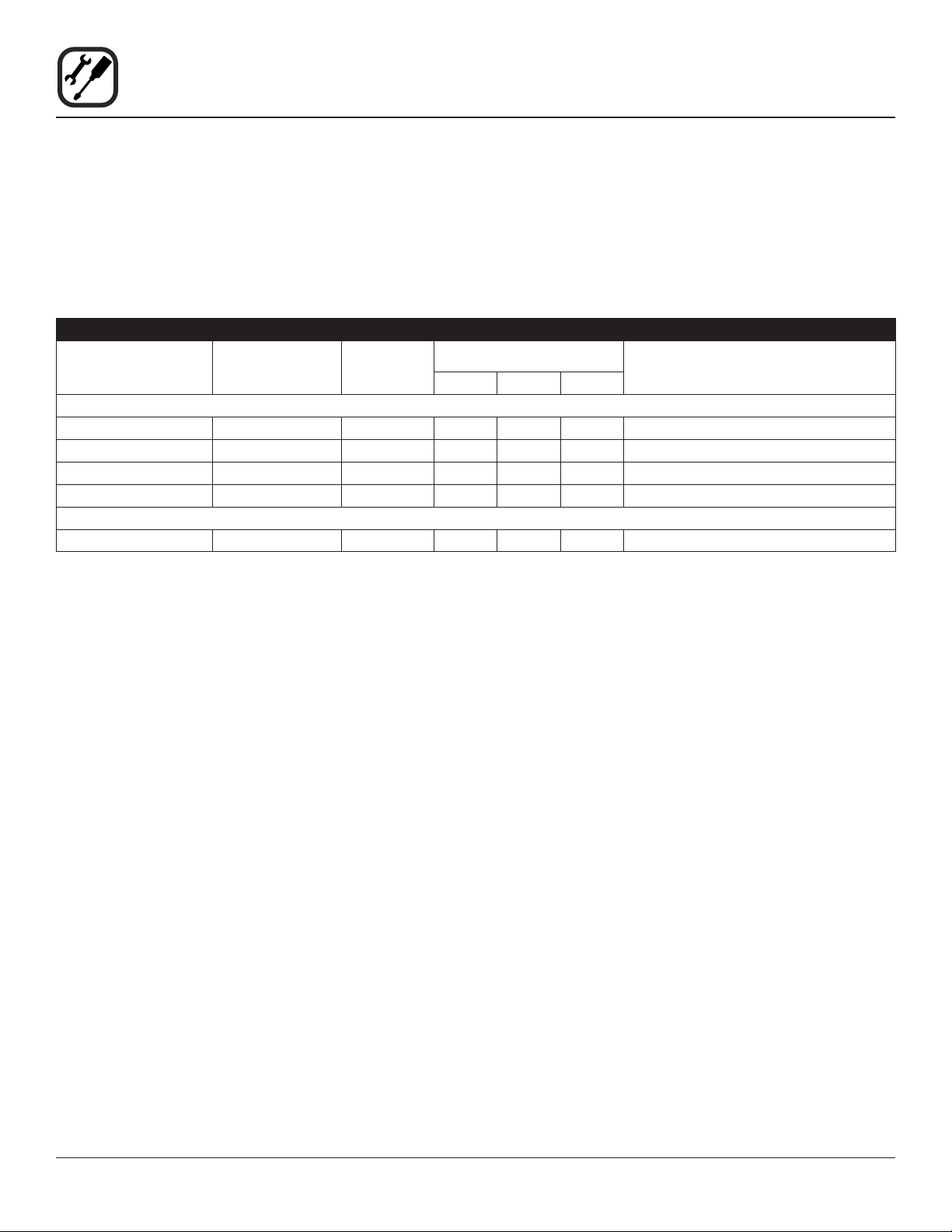
ELECTRICAL RATINGS- 1415
VOLTAGE
60 HZ
208 3.75 1 18 0 18 12
208 3.75 3 11 11 11 14
220-240 3.75 1 17 0 17 12
220-240 3.75 3 10 10 10 14
50 HZ
220-240 3.75 1 17 — 17 Size per local codes
NOTE: Double units can have phase loads partially equalized by matching lines during hook-up. Otherwise, load ratings are
double the above data.
KW/SECTION
PHASE
Features include a full angle iron frame, all welded radius
corners and stainless steel exteriors.
MAX LOAD (AMPS)
L1 L2 L3
ELECTRICAL CONNECTION AWG*
2
Page 5

Installation
Delivery and Location
DELIVERY AND INSPECTION
All Blodgett ovens are shipped in containers to prevent
damage. Upon delivery of your new oven:
• Inspect the shipping container for external damage.
Any evidence of damage should be noted on the
delivery receipt which must be signed by the driver.
• Uncrate the oven and check for internal damage.
Carriers will accept claims for concealed damage if
notied within fteen days of delivery and the shipping container is retained for inspection.
The Blodgett Oven Company cannot assume responsibility for loss or damage suffered in transit. The carrier assumed full responsibility for delivery in good order when
the shipment was accepted. We are, however, prepared
to assist you if ling a claim is necessary.
OVEN LOCATION
The well planned and proper placement of your oven will
result in long term operator convenience and satisfactory
performance.
Be sure to place the oven in an area which is accessible
for proper operation and servicing.
It is essential that ventilation air not be obstructed in any
way if proper operation is to be assured. A minimum of
two inches (5 cm) must be maintained between both the
sides and the rear of the unit and any wall.
3
Page 6

Installation
Electrical Connection
Ovens are supplied for operation on 208 volt or 220-240
volt installation. The thermostat, indicator light and related
switches are interconnected through one power source
supplied to the oven.
Before making any connection to this oven, check the rating plate attached to the bodyback to assure that the voltage, phase and KW rating are compatible with the electrical supply. See diagram.
All ovens, when installed, must be connected and electrically grounded in accordance with local codes, or in the
absence of local codes, with the National Electrical Code,
ANSI/NFPA 70-Latest Edition and/or Canadian Electric
Code CSA C22.1 as applicable.
Wiring diagrams are located on the bodyback.
The supply conduit enters through the rear of the oven
and electrical connection is made to the terminal block
secured to the panel at the back of the control compartment. Electrical connection sizes for a double 1400 oven
are shown in “Electrical Connection AWG” column of the
Electrical Specications found on page 2 of this manual.
Wiring is sized for 75_C copper wire at 125% of rated
input. Reference is from the National Electric Code ANSI/
NFPA 70- Latest Edition.
Wiring Label
Rating Plate
Wiring
Schematic
Installation Instructions
“Do not install closer than 2 inches to
any side or rear wall”
Figure 1
4
Page 7

Installation
Oven Assembly
PACKAGING
Before assembly and installation of the oven, check that
all components have been received. In addition to the
oven, legs, decks and/or other accessories may be re-
quired.
Single Sections
• 4” (10 cm) legs are shipped inside the oven, packed
in a separate carton.
• The decks are individually packaged and secured to
the oven back.
Double Sections
• 4” (10 cm) legs are packed in lower sections.
• Spacer is shipped attached to the upper section.
• Securing plate to attach units together is located in
the upper section.
• The decks are packaged with each section.
LEG ATTACHMENT
1. Tip bottom oven section backward.
2. Attach each of the four legs into the nuts secured in
the oven bottom.
3. Tighten each leg and adjust the leg feet to approximately the same height.
NOTE: Final leg fet adjustment will be required dur-
ing the leveling operation.
Figure 2
5
Page 8

Installation
Oven Assembly
STAND ASSEMBLY
1. Attach legs to stand frame. Secure with 5/16-18 nuts
and lockwashers (4 per leg). DO NOT TIGHTEN.
2. Place shelf on legs. Holes in legs should align with
holes in shelf corner brackets. Legs should be loose
enough to assist in this alignment. Place 1/4-20
x 2-1/4” bolts through legs and into shelf brackets.
Bolts should t radius of legs. Install 1/4-20 nuts after
all four corners are in place. Tighten four nuts. Do not
over tighten these nuts, deformity of leg surface can
occur.
3. Tighten the sixteen 5/16-18 nuts installed in Step 1.
DO NOT over tighten.
4. Optional Caster Assembly - Secure caster by tightening with a wrench. Prior to placing oven section on
stand, check that locking casters are on front of stand
assembly.
5. Center oven on stand assembly.
DOUBLE STACKING
1. Connect the spacer assembly to the bottom of th upper unit using 4 hex bolts.
2. Align and secure the spacer connecting plate to the
lower unit using 4 sheet metal screws.
NOTE: First remove the 4 sheet metal screws along
the top edge of the lower unit panel.
3. Stack the upper unit on top of the lower unit.
4. Align and secure the spacer connecting to the spacer
assembly using 4 sheet metal screws.
Figure 3
Figure 4
6
Page 9

Installation
Oven Assembly
DECK INSTALLATION
1. Remove the decks from the carton package.
NOTE: Handle cordierite shelves carefully to avoid
damage.
2. Open the oven door and remove the center element
assembly. The assembly is removed by puling forward and unplugging.
3. Install one of the decks in the bottom position. The
deck should rest on the angles above the element
and should be positioned in contact with the linerback.
4. Install the other deck in the center element assem-
bly on a at surface. Reinstall the center deck and
element assembly in the oven. The assembly is supported on four angle supports.
LEVELING THE OVEN
1415 ovens are equipped with NSF listed adjustable sanitary legs.
1. Level the oven side to side and front to back by placing a spirit level on the base frame of the lower section.
2. Adjust the leg feet in or out as necessary.
Bottom Deck
Center Element
Figure 5
7
Page 10

Operation
Oven Control
1
OFF ON
COMPONENT DESCRIPTION
1. POWER SWITCH - Controls the power to the oven.
2. DIGITAL DISPLAY - Displays the time, temperature
and controller related information.
3. DIAL - Turn to set the cook time and temperature.
4. START/STOP KEY - Press to start and stop the timing cycle.
5. TIME KEY - Press to enter the cook time.
6. TEMP KEY - Press to enter the cook temperature.
2
OPERATION
1. Toggle the POWER SWITCH (1) to OVEN ON.
2. Press the TEMP KEY (6) and turn the DIAL (3) to select the desired cook temperature.
HEAT
3. When the display reads LOAD, press the TIME KEY
(5) and turn the DIAL (3) to select the desired cook
time.
4. Load product into the oven.
3
5. Press START/STOP KEY (4). The timer counts down
the set time. Upon completion of the set time, the
buzzer sounds and the display reads DONE.
6. Press the START/STOP KEY (4) to silence the buzz-
4
START
STOP
TIME TEMP
5
er.
7. To shut the oven off, toggle the POWER SWITCH (1)
to OFF.
6
DISCONNECT THIS UNIT FROM THE SOURCE
OF SUPPLY BEFORE SERVICING
www.blodgett.com
Figure 6
8
Page 11

EXTERIOR SURFACE CLEANING
Stainless steel surface may be kept clean and in good
condition with mineral oil:
1. Allow the oven to cool.
2. Saturate a cloth with mineral oil and wipe the oven.
3. Wipe dry with a clean cloth.
Baked-on splatter on the stainless exterior may be removed with any non-toxic stainless steel cleaner:
1. Follow directions on your cleaning agent.
2. Apply with a cloth, rubbing with the grain of the metal.
CAUTION!!
DO NOT use abrasive cleaning cloths as this
will scratch the nish of the stainless steel.
INTERIOR CLEANING
Deck Surface
1. Place the crumb tray on the oven door. See Figure 7.
Maintenance
Cleaning and Preventative Maintenance
Figure 7
2. Using a scraper/brush (Figure 8), scrape the decks to
remove baked on splatter.
3. Using the brush, clean the deck until smooth.
4. Using a damp cloth, lightly wipe down the surface of
the deck.
CAUTION!!
Stones must be at room temperature.
CAUTION!!
Excessive water will be absorbed into the
stone and risk of cracking may result. In the
event of water absorbtion, see Deck Stone
Dry-Out Procedure on the following page to
avoid cracking.
Figure 8
Oil Spills
If oil spills on deck, DO NOT WIPE:
1. Pour Kosher salt on the spill.
2. Allow to absorb.
Follow steps 1-4 under Deck Surface to remove the Kosher salt residue.
9
Page 12

Maintenance
Cleaning and Preventative Maintenance
Interior Walls
The aluminized surface may be kept clean and in good
condition with mineral oil:
1. Allow the oven to cool.
2. Large amounts of baked on splatter may be removed
with a brass scraper, gently applied.
3. Saturate a cloth with mineral oil and wipe the oven.
4. Mild dish detergent and water may also be used to
clean the interior walls but be carefull not to spill water on the stone decks.
5. Wipe dry with a clean cloth.
6. Remove residue from beneath the oven door with a
small brush.
CAUTION!!
DO NOT use caustic solutions such as ammonia, lye or soda ash. DO NOT use domestic
oven cleaners. Any of these products will
damage the aluminum coating.
Deck Stone Dry-Out Procedure
If excess water is absorbed by the stone and then quickly heated, the boiling water expands and may crack the
stone. To prevent cracking perform one of the following
dry-out procedures:
1. Dry stones overnight at room temperature with the
door open.
PREVENTATIVE MAINTENANCE
The best preventative maintenance measures are, the
proper installation of the equipment and a program for
routinely cleaning the ovens.
This oven requires no lubrication, however, the venting
system should be checked annually for possible deterio-
ration resulting from moisture and corrosive ue products.
If maintenance or repairs are required, contact the fac-
tory, the factory representative or a local Blodgett service
company.
WARNING!!
Disconnect the oven from the power supply
before servicing. It is not necessary to unplug
the oven when cleaning.
2. Set oven to 150ºF for 2 hours to slowly dry out the
stone.
WEEKLY CLEANING
• Brush out the control area.
6 MONTH CLEANING
• Clean secondary air ducts and air entry ports.
10
Page 13

POSSIBLE CAUSE(S) SUGGESTED REMEDY
SYMPTOM: Strong bottoms on the bakes
• Too much bottom heat
Maintenance
Troubleshooting Guide
• Reduce cook temperature and increase time
• Product left in the oven too long
SYMPTOM: Uneven bakes
• Oven doors left open too long
• Improper scaling of dough
• Warped pans
• Uneven product loading
SYMPTOM: Product burning
• Thermostat set too high
• Product left in the oven too long
• Thermostat out of calibration
SYMPTOM: Product dried out
• Oven temperature too low
• Not using enough water in the mix
• Thermostat out of calibration
SYMPTOM: Extended baking times
• Temperature setting too low
• Shorten cook time
• Do not open door unnecessarily
• Scale dough consistently
• Change pans
• Be sure to load the product evenly in pans
• Reduce cook temperature
• Shorten cook time
• *
• Increase cook temperature
• Increase water in product mix
• *
• Increase cook time
• Excessive door openings
*Denotes remedy is a difcult operation and should be performed by qualied personnel only. It is recommended, however, that All repairs and/or adjustments be done by your local Blodgett service agency and not by the owner/operator.
Blodgett cannot assume responsibility for damage as a result of servicing done by unqualied personnel.
WARNING!!
Disconnect the oven from the power supply before servicing. It is not necessary to unplug the oven when
cleaning.
• Do not open door unnecessarily
11
 Loading...