

Page 1

1048
GAS DECK OVEN
INSTALLATION -- OPERATION -- MAINTENANCE
1048
FOURS À GAZ À PLATEFORME
MANUEL D’INSTALLATION -- UTILISATION -- ENTRETIEN
44 Lakeside Avenue, Burlington, Vermont 05401 USA Telephone (800) 331-5842, (802) 860-3700 Fax: (802)864-0183
BLODGETT OVEN COMPANY
www.blodgett.com
PN 18648 Rev E (6/01)
E 2001 --- G.S.Blodgett Corporation
Page 2

IMPORTANT
WARNIN G:IMPROPERINSTALLATION,ADJUSTMENT,ALTERA TI O N ,SERVICE OR
MAINTENAN C ECAN CAUSEPROPERTYDAMAGE,INJURY OR DEATH.READTHE
INSTALLA TION,OPERATING AND MAINTENANCE INSTRUCTIONS THOROUGHLY
BEFORE INSTALLING OR SERVICING THIS EQUIPMENT
AVERTI SSEMEN T: UNE INSTALLATION , UN AJUSTEMENT, UNE ALTÉRATIO N, UN
SERVICEOU UN ENTRETIENNON CONFORME AUXNORMESPEUT CAUSERDES
DOMMAGESÀLAPROPRIÉTE,DESBLESSURESOU LAMORT.LISEZATTENTIVEMENTLES DI REC TI V ESD’INS TALLATION,D’OPÉRATIONET D’ENTRETIENAV A NT
DE FAIRE L’IN S TALLATION OU L’ENTRETI EN DE CET ÉQUIPEMENT.
INSTRUCTIONS TO BE FOLLOWED IN THE EVENT THE USER SMELLS GAS
MUST BE POSTED IN A PROMINENT LOCATION. THIS INFORMATION MAY BE
OBTAINED BY CONTACTING YOUR LOCAL GAS SUPPLIER.
LES INSTRUCTIONSÀ RESPECTER AUCAS OÙ L’UTILISATEUR PERÇOIT UNE
ODEURDE GAZ DOIVENT ÊTRE AFFICHÉES DANS UNENDROITBIEN VISIBLE.
VOUS POUVEZ VOUS LES PROCURER AUPRÈS DE VOTRE FOURNISSEUR DE
GAZ LOCAL.
FORYOURSAFETY
Do not store or use gasoline or other flammable vapors or liquids in the vicinity
of this or any other appliance.
AVERTISSEMENT
Ne pas entreposer ni utiliser de l’essence ni d’autres vapeurs ou liquides inflammables dans le voisinage de cet appariel, ni de tout autre appareil.
The information contained in thismanual isimportant for the properinstallation,
use,and maintenanceofthisoven. Adherenceto theseproceduresand instructions will result in satisfactory baking results and long, trouble free service.
Please read this manual carefully and retain it for future reference.
Les informatio nsdonnées dans le présent manuel sont importantes pour installer ,
utiliseret entret en ir correctementce four. Le respect de ces instr uct ions et procédurespermettra d’obtenir de bonsrésultatsde cuissonet une longue durée deservice sans problèmes. V euillez lire le présent manuel et le conserver pour pouvoir
vous y reporter à l’avenir.
Errors: Descriptive, typographic or pictorialerrors aresubject to correction.Specifica-
tions are subject to change without notice.
Erreurs:Les erreurs de description, de typographie ou d’illustration font l’objet de
corrections. Les caractéristiques sont sujettes à modifications sans préavis.
Page 3

THE REPUTATION YOU CAN COUNT ON
UNE RÉPUTATION SUR LAQUELLE VOUS POUVEZ COMPTER
Forover acentury and a half,The Blodgett OvenCompany has beenbuilding
ovensand nothing but ovens. We’veset theindustry’s quality standard for all
kinds of ovens for every foodservice operation regardless of size, application
or budget. In fact, no one offers more models, sizes, and oven applications
than Blodgett;gas andelectric, full-size,half-size, countertopand deck, convection, Cook’n Hold,Combi-Ovens and the industry’s highest quality Pizza
Oven line. For more information on the full line of Blodgett ovens contact your
Blodgett representative.
Celafait maintenantdessus un siècleet demiqueBlodgettse spécialisedans
la fabrication de fours. Nous avons établi les normes de qualité qui s’appliquent dans l’industrie à tous les types de fours utilisés dans les services alimentaires,quelqu’en soitlat aille,l’exploitationoule budget.En fait, nin’offre
plus de modèles, de tailles et d’applications de fours que Blodgett. À gaz et
électriques. De tailles différentes, sur plan de travail et superposables. Qu’il
s’agisse de foursà convection,desmodèlesCook’n Holdet Combi-Oven,ou
de la gamme de foursà pizzasde la plus haute qualitéofferte sur le marché.
Pourde plusamples informations sur lagamme complètede foursBlodgett,
veuillez contacter votre représentant Blodgett.
Page 4

Your Service Agency’s A ddress:
Adressedevotreagencedeservice:
Model/Modèl:
Serial Number/Numéro de série:
Your oven was installed by/
Installateur de votre four:
Your oven’s installation was checked by/
Contrôleur de l’installation de votre four:
Page 5

Table of Contents/Table des Matières
Introduction
Oven Description and Specifications 2....
Oven Components 3....................
Installation
Delivery and Location 4.................
Oven Assembly 5......................
Packaging 5..........................
Leg Attachment 5.....................
caster attachment 5...................
Double Section Assembly 6............
3 Piece Deflector Assembly 6...........
Ultra Rokite Shelves 6.................
Deck Seal 7..........................
Flue Plates 7.........................
Leveling the Oven 7...................
Adjustments Associated with Initial
Installation 7.........................
Ventilation 8...........................
Canopy Type Exhaust Hood 8..........
Direct Flue Arrangement 9.............
Venting Problems 9...................
Utility Connections ---
Standards and Codes 10.................
Gas Connection 11......................
Operation
Safety Information 14....................
Oven Control 15.........................
General Guidelines for Operating
Personnel 16............................
Maintenance
Cleaning and Preventative Maintenance 17.
Troubleshooting Guide 18................
Introduction
Description et Spécifications du Four 20....
Éléments du Four 21.....................
Installation
Livraison et Implantation 22...............
Montage du Four 23.....................
Emballage 23.........................
Assemblage des Pieds 23...............
Fixation des Roulettes 23...............
Montage de la Section Double 24........
Montage du Déflecteur en Trois
Parties 24.............................
Des Plaques en Rokite 24...............
Joint de Plaque 25.....................
Plaques de Cheminée 25...............
Mise à Niveau des Fours 25.............
Réglages à Faire Lors de
l’Installation Initiale 25..................
Ventilation 26...........................
Hotte D’évacuation Type Voûte 26.......
En Prise Directe 27.....................
Problêmes de la Ventilation 27...........
Branchements de Service --- Normes et
Codes 28...............................
Branchement de Gaz 29.................
Utilisation
Information de Sécurité 32................
Les Commandes du Four 33..............
Consignes Générales à l’Intention des
Utilasateurs 34..........................
Entretien
Nettoyage et Entretien Préventif 35........
GuidedeDétectiondesPannes 36........
Page 6
Introduction
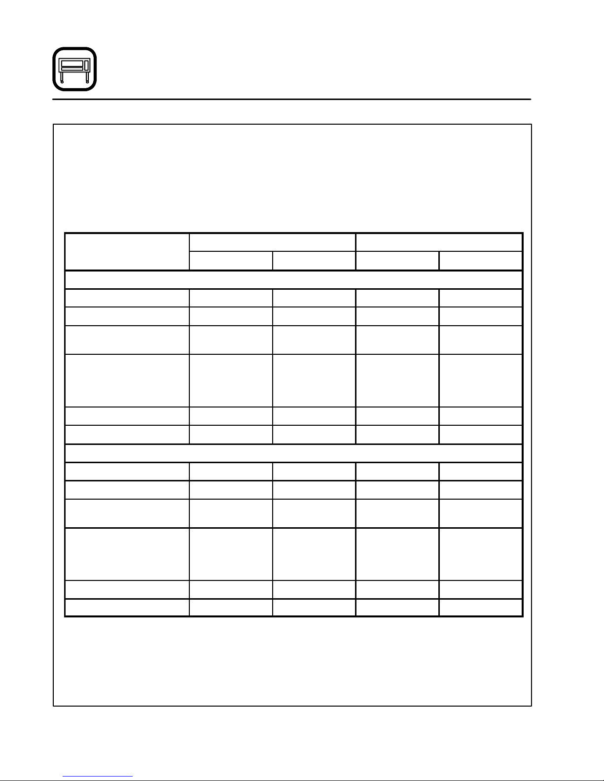
Oven Description a nd Specifications
Blodgett Deck ovens have set industry wide standards of excellence for baking characteristics,
performance and reliability. They remain unsurpassed for product quality.
Simplicity of design and quality construction
throughout assure years of trouble free service
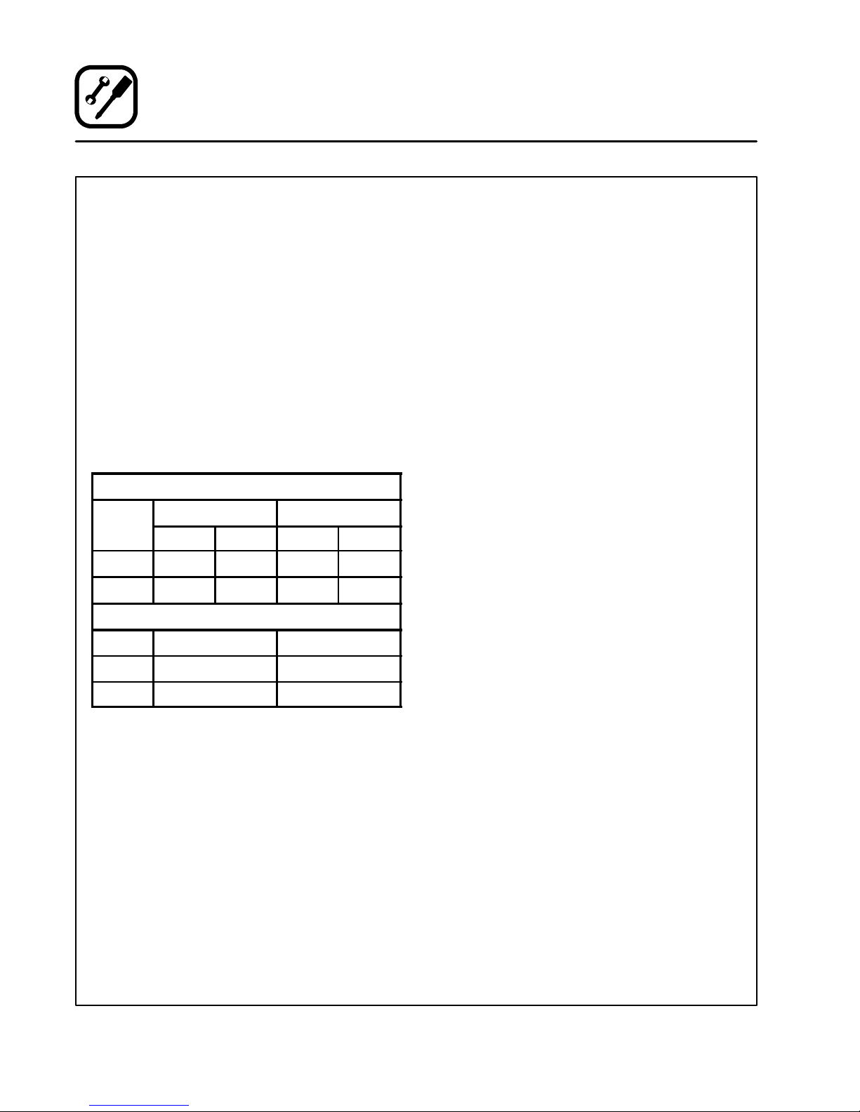
Natural Gas Propane Gas
US Units SI Units US Units SI Units
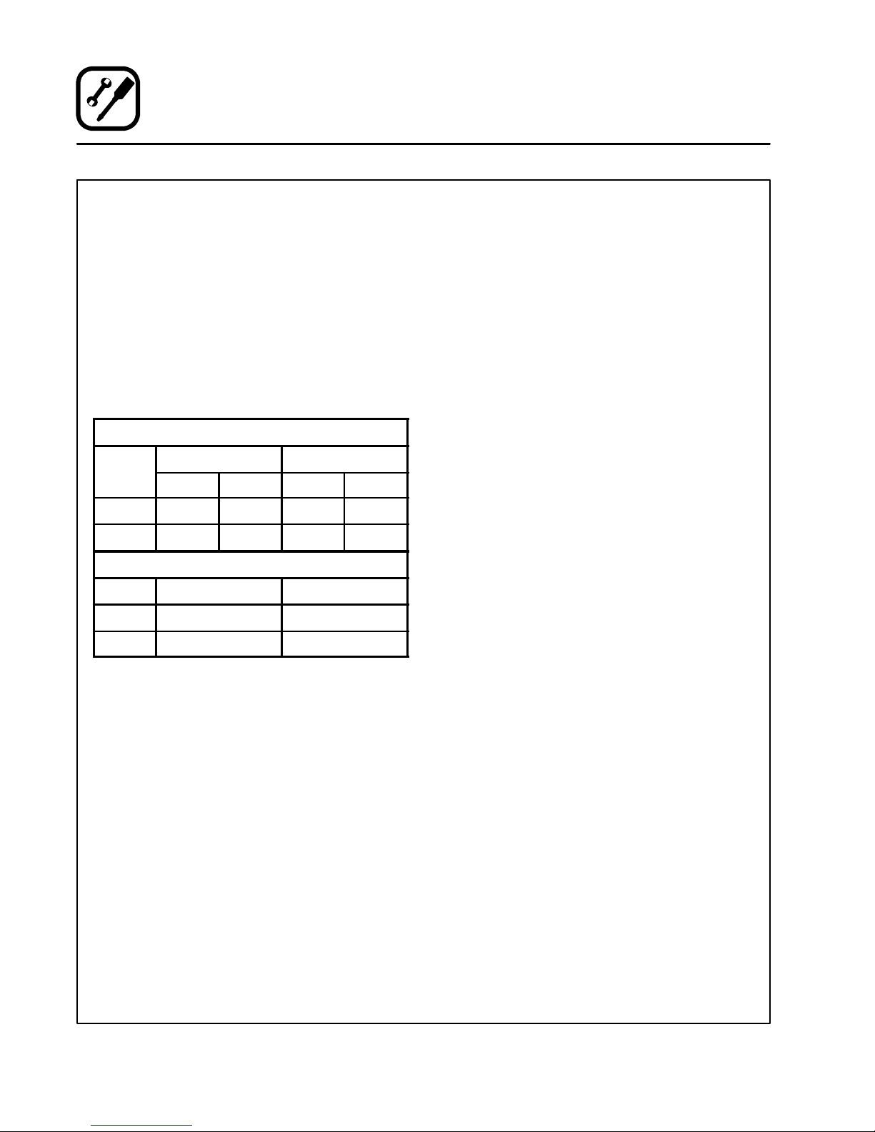
1048-BL GAS SPECIFICATIONS
Heating Value 1000 BTU/hr 37.3 MJ/m
Specific Gravity (air=1.0) 0.63 0.63 1.53 1.53
Gas Manifold Pressure 3.5” W. C. 0.87 kPa 10” W.C. 2.49 kPa
Oven Input
Per Burner
Per Oven
Main Burner Orifice Size 30 MTD* 3.3 mm 48 MTD* 1.93 mm
Pilot Burner Orifice Size .018” Dia. .46 mm .010” Dia. .25 mm
1048-B GAS SPECIFICATIONS
Heating Value 1000 BTU/hr 37.3 MJ/m
42,500 BTU/hr
85,000 BTU/Hr
when the equipment is properly installed and
maintained.
Features include a fullangle iron frame, allwelded
radius corners and stainless steel fronts and
doors.
3
12.4 kW
24.9 kW
3
2550 BTU/hr 95.0 MJ/m
42,500 BTU/Hr
85,000 BTU/Hr
2550 BTU/hr 95.0 MJ/m
12.4 kW
24.9 kW
3
3
Specific Gravity (air=1.0) 0.63 0.63 1.53 1.53
Gas Manifold Pressure 3.5” W. C. 0.87 kPa 10” W.C. 2.49 kPa
Oven Input
Per Burner
Per Oven
Main Burner Orifice Size 23 MTD* 3.9 mm 44 MTD* 2.18 mm
Pilot Burner Orifice Size .018” Dia. .46 mm .010” Dia. .25 mm
NOTE: *Multiple Twist Drill
Gas Specifications are supplied in both US and SI (International Standard) units.
60,000 BTU/hr
120,000 BTU/Hr
2
17.6 kW
35.2 kW
60,000 BTU/Hr
120,000 BTU/Hr
17.6 kW
35.2 kW
Page 7
Introduction
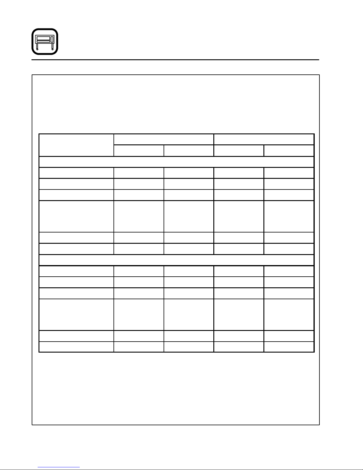
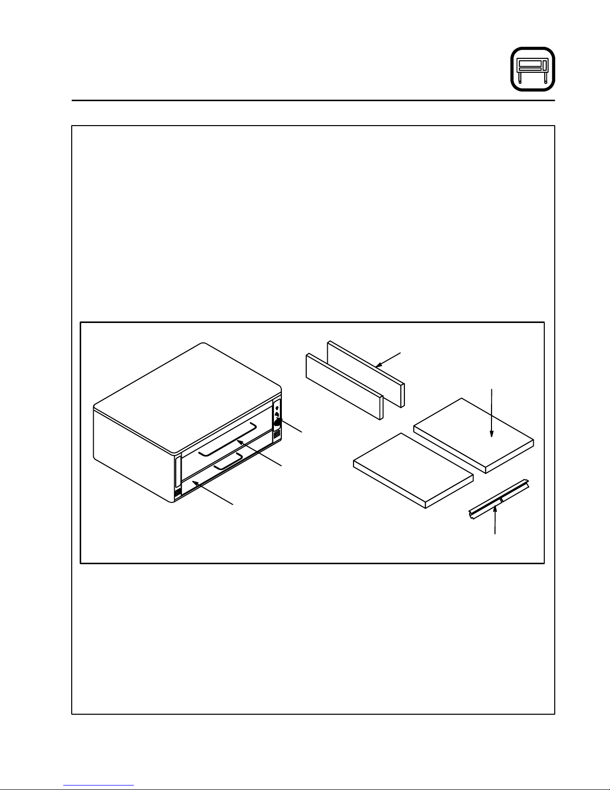
Oven Components
UltraRokite Deck --- stonedeckthat absorbs heat
from below to cook the bottom of the product.
Steel Deck --- absorbs heat from below to cook
the bottom of the product.
Deck Supports --- hold the oven decks.
DeckSeal --- seals thegapbetweenthe deck and
the front of the oven.
Control Panel --- containswiringandcomponents
to control the oven operation.
Burner Compartment --- located beneath the
cooking chamber. The burner compartment contains the combustion burners.
Combustion Burners --- provide heat to the baking chamber and the decks.
Deflector --- diverts some of the heat from the
combustion burners to t he flue plates.
Flue Plates - -- located on the interior side walls of
the cooking chamber. The flue plates conduct
heat from the burners tothe ovencavity.The heat
cooks the top of the product before beingvented
from the oven.
Flue Plates
Oven Decks
Control
Panel
Burner
Compartment
Baking
Compartment
Deck Seal
Figure 1
3
Page 8

Installation
Delivery and Location
DELIVERY AND INSPECTION
All Blodgett ovens are shipped in containers to
preventdamage. Upondeliveryofyour new oven:
D
Inspecttheshippingcontainerfor externaldamage. Any evidenceof damageshould ben oted
onthe deliveryreceipt which must be signedby
the driver.
D
Uncrate the oven and check for internal damage. Carriers will accept claims for concealed
damage if notified within fifteendays ofdelivery
and the shipping container is retained for inspection.
The Blodgett Oven Company cannot assume
responsibility for loss or damage suffered in
transit. The carrier assumed full responsibility
for delivery in good order when the shipment
was accepted. We are, however, prepared to
assist you if filing a claim is necessary.
OVEN LOCATION
The well planned and proper placement of your
oven will result in long term operator convenience
and satisfactory performance.
The following clearances mustbe maintained between the ovenand any combustible or non-combustible construction.
D
Oven body right side --- 6” (15 cm)
D
Oven body left side --- 6” (15 cm)
D
Oven body back --- 6” (15 cm)
D
Oven body bottom --- 6” (15 cm)
The followingclearance mustbe availablefor servicing.
D
Oven body left side --- 12” (30.5 cm)
NOTE: Ongas models,routineservicingcanusu-
ally be accomplished within the limited
movement provided by the gas hose restraint. If the oven needs to be moved further from the wall, the gas must first be
turned offand disconnectedfrom theoven
before removing the restraint. Reconnect
the restraint after the oven has been returned to its normal position.
It is essential that an adequate air supply to the
oven be maintained to provide a sufficient flow of
combustion and ventilation air.
D
Place the oven in an area that is free of drafts.
D
Keeptheovenarea freeand clearofallcombustiblessuchas paper,cardboard, andflammable
liquids and solvents.
D
Do not place the ovenon a curb baseor seal to
awall.Thiswillrestrict the flow ofair andprevent
properventilation. Pilotoutages or yellow,floating flames onthe main burners are indicative of
a lack of secondary air.
D
The oven must be installed with the legs supplied by the manufacturer.
Beforemakinganyutilityconnectionsto thisoven,
check the rating plate to be sure the oven specifications are compatible with the gas and electrical
services supplied for the oven. The rating plate is
located on the inside of the burner door.
4
Page 9

Installation
Oven Assembly
PACKAGING
Before beginning assembly and installationof the
oven, check that all necessary componentshave
been received. In addition to the oven itself, legs,
the proper vent, and/or otheraccessories may be
required.
Single Sections
1048 with Steel Deck
D
Legs, regulator, set of flue plates, draft diverter
and steel deck are shipped in the oven.
D
Drafthood (when supplied) is packed separately.
1048 with Ultra Rokite Decks
D
Legs, regulator, set of flue plates and draft diverter are shipped in oven.
D
UltraRokitedecksarepackedinaseparatecarton.
D
Drafthood (when supplied) is packed separately.
Double Sections
1048 with Steel Deck
D
Legs and bolts, regulator, set of flue plates and
steel deck are packed in the lower section.
D
Regulator , set of flue plates, draft diverter and
steel deck are packed in the upper section.
D
Crown angle leg frame is packed in a separate
carton.
D
Drafthood(when supplied)is packed in a separate carton.
1048 with Ultra Rokite Decks
D
Legs and bolts, regulator, set of flue plates are
packed in the lower section.
D
Regulator, draft diverter and a set of flueplates
are packed in the upper section.
D
UltraRokitedecksarepackedintwoseparate
cartons.
D
Crown angle leg frame is packed in a separate
carton.
D
Drafthood(when supplied)is packed in a separate carton.
LEG ATTACHMENT
1. Put the oven onto a genie lift w ith the bottom
of the oven down.
2. Each leg is attached by three bolts to the underside of the oven base frame.
CASTER ATTACHMENT
1. Boltsupportstoovenwith1/2-13hexhead
bolts(casterswithbrakesshouldbefacing
front of oven.)
2. Carefully place oven onto the casters. (It will
benecessary tohave severalpersons liftoven
off the pallet and set it onto the casters). Engage brakes on front casters.
NOTE: A fixed restraint must be provided if cast-
ers are used in conjunction with a flexible
connector for movable appliances. This
restraint must secure the oven to a nonmovablesurfaceto eliminatestress onthe
connector. If the oven is moved, the restraint must be reconnected after the oven
is returned to it’s normal position.
5
Page 10
Installation
Oven Assembly
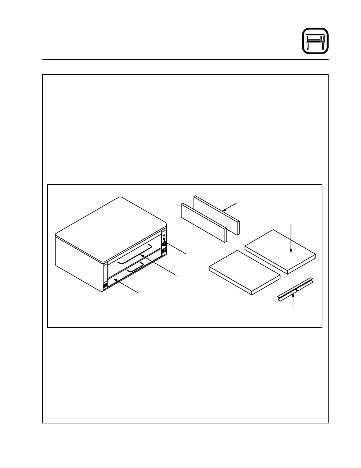
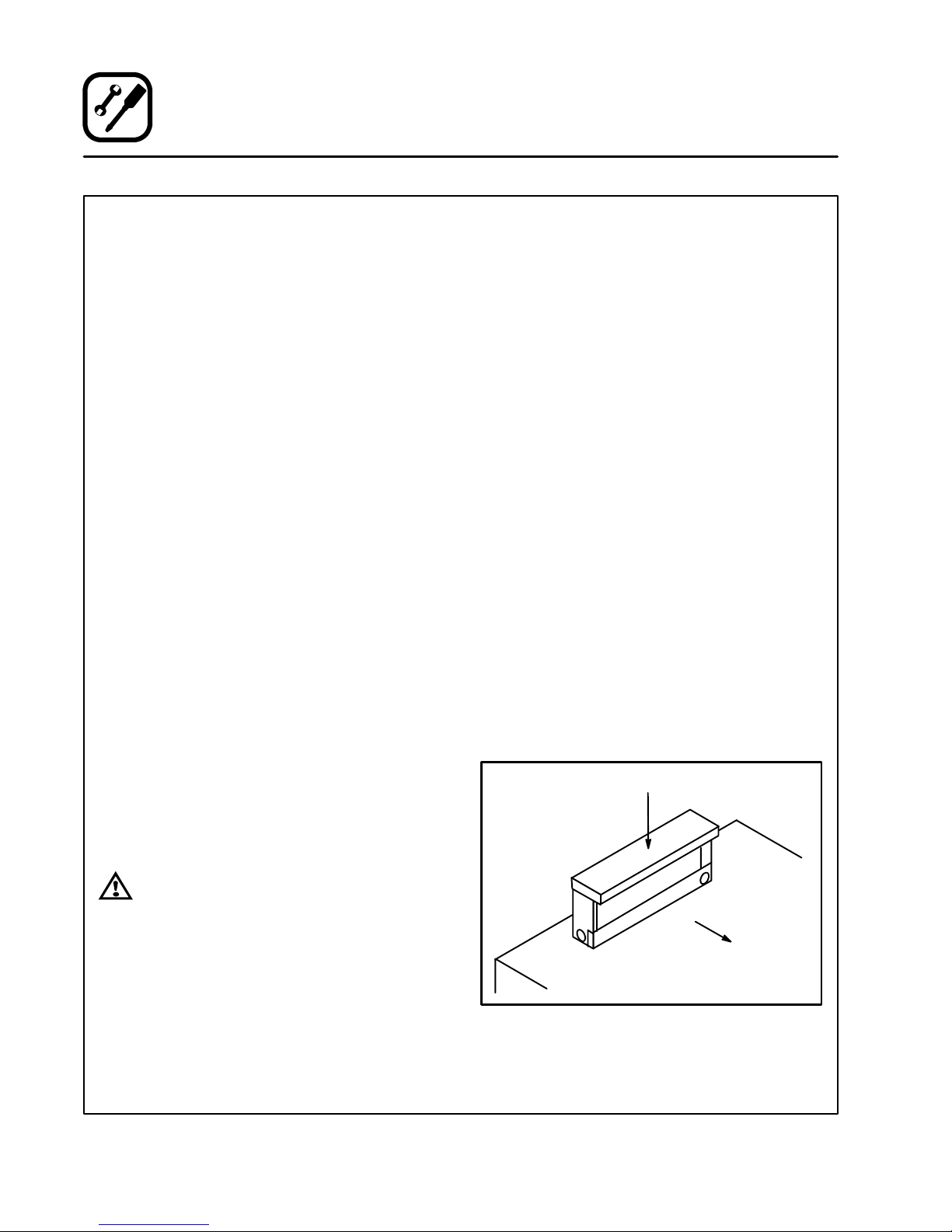
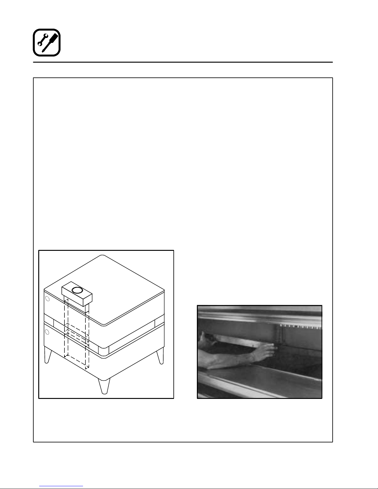
DOUBLE SECTION ASSEMBLY
1. Fasten 12” (305 mm) legs to lower section.
2. Remove the sheet metal fluecover on bottom
of UPPER SECTION FLUE ONLYand savethe
two screws.
3. Fasten crown angle leg frame to upper sections.
4. Insert double oven flue connector into upper
oven section flue until it is flush with the base
angle. Temporarily hold in place with tape.
5. Install upper section on bottom section.
6. Remove tape and slide flue connector into
position over the collar of the bottom section.
SeeFigure2.
7. Fasten flue connector to bottom section with
screwsfromthefluecover.
8. Install drafthood or draft diverter with screws
provided.
3PIECEDEFLECTORASSEMBLY
1. Deflectorsare shippedinplacein theoven.No
assembly is required.
2. Remove the shipping clip located in the back
center of each deflector before inserting twopiece shelf assembly.
ULTRA ROKITE SHELVES
1. Slideone half ofthe Ultra Rokite shelft hrough
the door opening. Rest the shelfonthe deflector and slide to the rear of the oven until it
drops into the shelf support. Slidethe shelfto
the right.
2. Slidethe other half of the Ultra Rokite shelf on
top of first shelf to the rear until it is within the
shelfsupport. Slideitallthewaytot he leftuntil
it drops down into place.
3. Slide both shelf halves inward so the center
joint closes.
4. Refer to pre-heatinginstructions supplied with
Ultra Rokite.
NOTE: Because of the weight of the Ultra Rokite
shelves, take care to avoid injury to yourselfordamagetotheshelveswhensliding
sections into the oven. Use of 1” x 4”
piecesof lumber willhelp to slide shelves
into place.
Figure 2
Figure 3
6
Page 11
Installation
Oven Assembly
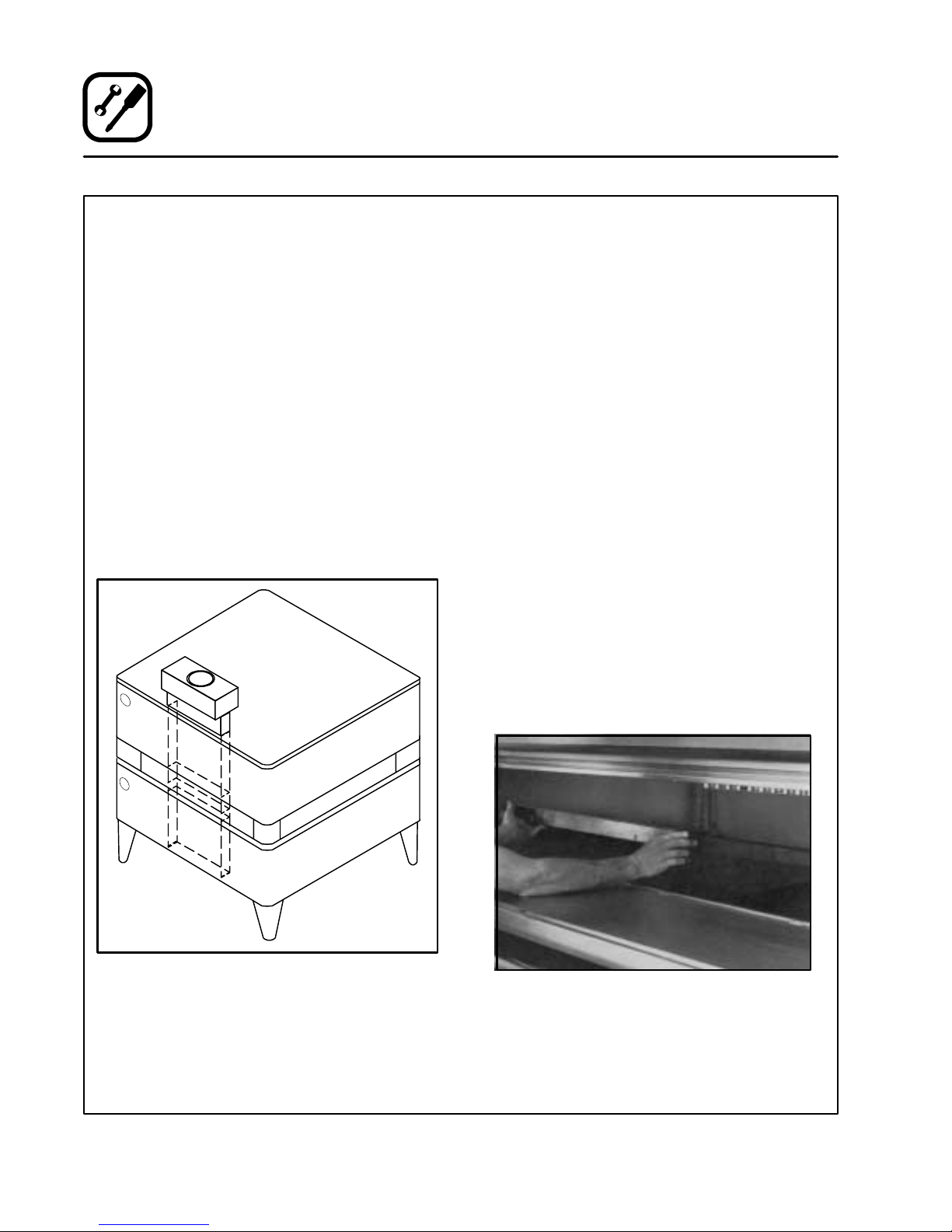
DECK SEAL
1. Placethelonglipofthe deckseal infrontofthe
shelf support angle. Place the shorter lip with
the notches between the shelf support angle
and the shelf.
2. Push seal down into place.
Figure 4
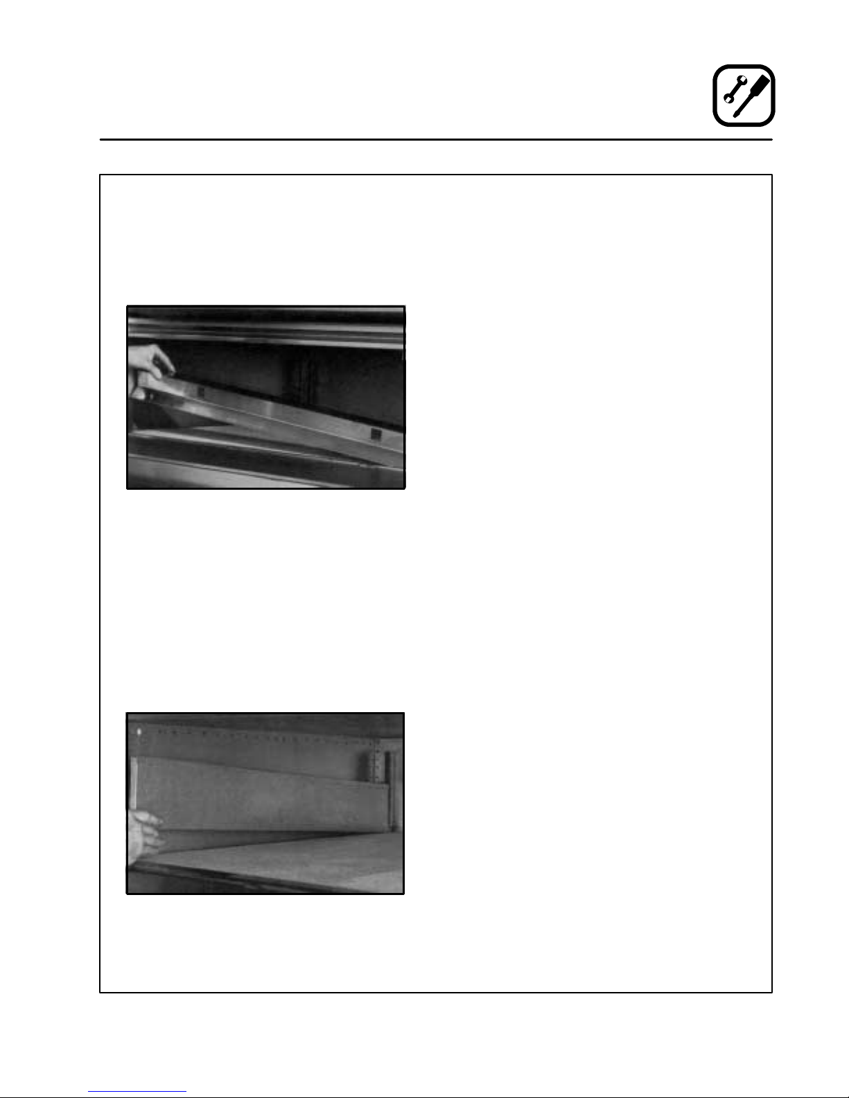
FLUE PLATES
1. Insertthe back endofthe flueplatein thevertical channel in the rear of the oven compartment.
2. Swing the flueplate outward toward the oven
side wall.
3. Raisethefrontendoftheflueplateabout1/2”.
slip the two tabs on the flue plate in the
matched angle on the front wall.
4. Drop the flue plate down into place.
LEVELING THE OVEN
Ovens are equipped with NSF listed adjustable
sanitary legs.
1. Level ovens side to side and front to back by
placingspiritlevel onbaseframeof lowersection.
2. Adjust leg feet in or out as appropriate.
ADJUSTMENTS ASSOCIATED WITH INITIAL
INSTALLATION
Each oven, and its component parts, have been
thoroughly tested and inspected prior to shipment. However, itis often necessary to further test
or adjust the oven as part of a normal and proper
installation. These adjustments are the responsibility of the installer, or dealer. Since theseadjustments are not considered defects in material or
workmanship,theyarenotcoveredbytheOriginal
Equipment Warranty. They include, but are not
limited to:
D
calibration of the thermostat
D
adjustment of the doors
D
burner adjustments
D
leveling
D
testing of gas pressure
D
tightening of fasteners
No installation should be considered complete
without proper inspection, and if necessary, adjustment by qualified installation or service personnel.
Figure 5
7
Page 12
Installation
Ventilation
Blodgett gasdeckovensare directfired. Heatand
flue products from the burners are introduced directly into the baking compartment. As a result,
improperventing can have a detrimentaleffect on
the baking characteristicsof the oven. A properly
designed ventilation system will allow the ovento
function properly, while removing unwanted vapors and products of combustion from the operating area.
This oven may be vented using either:
D
A mechanically driven, canopy type, exhaust
hood, or
D
A direct flue arrangement.
U.S. and Canadian installations
Refer to your local ventilation codes. In the absence of localcodes, refer to the Nationalventilation code titled, “Standard for the Installation of
Equipment for the Removal of Smoke andGrease
Laden Vapors from Commercial Cooking Equipment”, NFPA-96-Latest Edition.
General export installations
Installationmust conform with Local and National
installation standards. Local installation codes
and/or requirements may vary. If you have any
questionsregarding the proper installationand/or
operation of your Blodgett oven, please contact
yourlocaldistributor.If youdo nothavea localdistributor, pleasecallthe BlodgettOvenCompanyat
0011-802-860-3700.
THE BLODGETT OVEN COMPANY CANNOT ASSUMERESPONSIBILITYFORLOSSORDAMAGE
SUFFEREDAS ARESULTOFIMPROPERINSTALLATION.
CANOPY TYPE EXHAUST HOOD
A mechanicallydriven, canopytype exhaust hood
is the preferred method of ventilation.
The hood should be sized to completely cover the
equipmentplusan overhang of at least 6” (15 cm)
on all sides not adjacent to a wall. The distance
from the floor to the lower edgeof thehoodshould
not exceed 7’ (2.1m).
The capacity of the hood should be sized appropriately with provisions foran adequate supply of
make up air. Capacity is generally expressed in
3
ft
/min (CFM). 1 CFM of natural gas burned with
just enough air for complete combustion produces 11 CFM of combustionproducts. Invirtually
all appliances some excess air is used. This volume of excess air is added to the flue products
flowing from the appliance.
NOTE: Consult your local exhaust hood contrac-
tor for your specific installation.
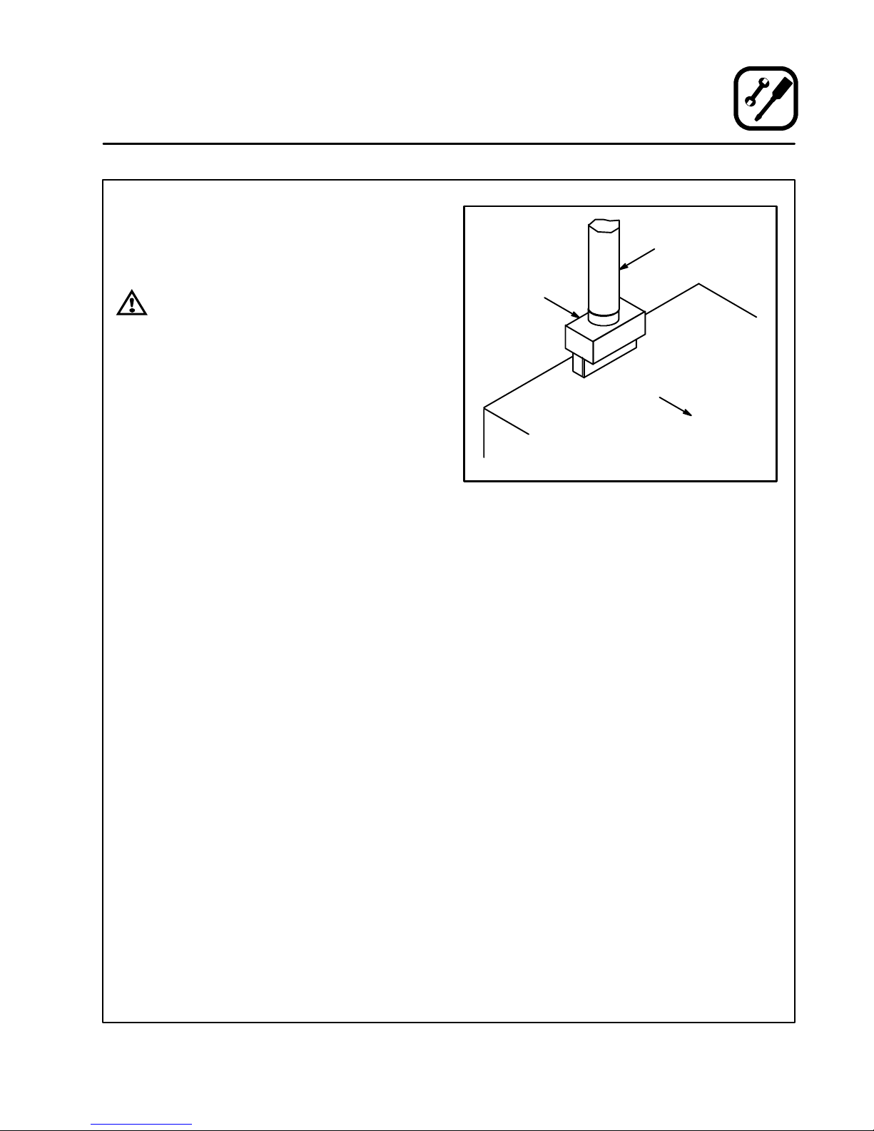
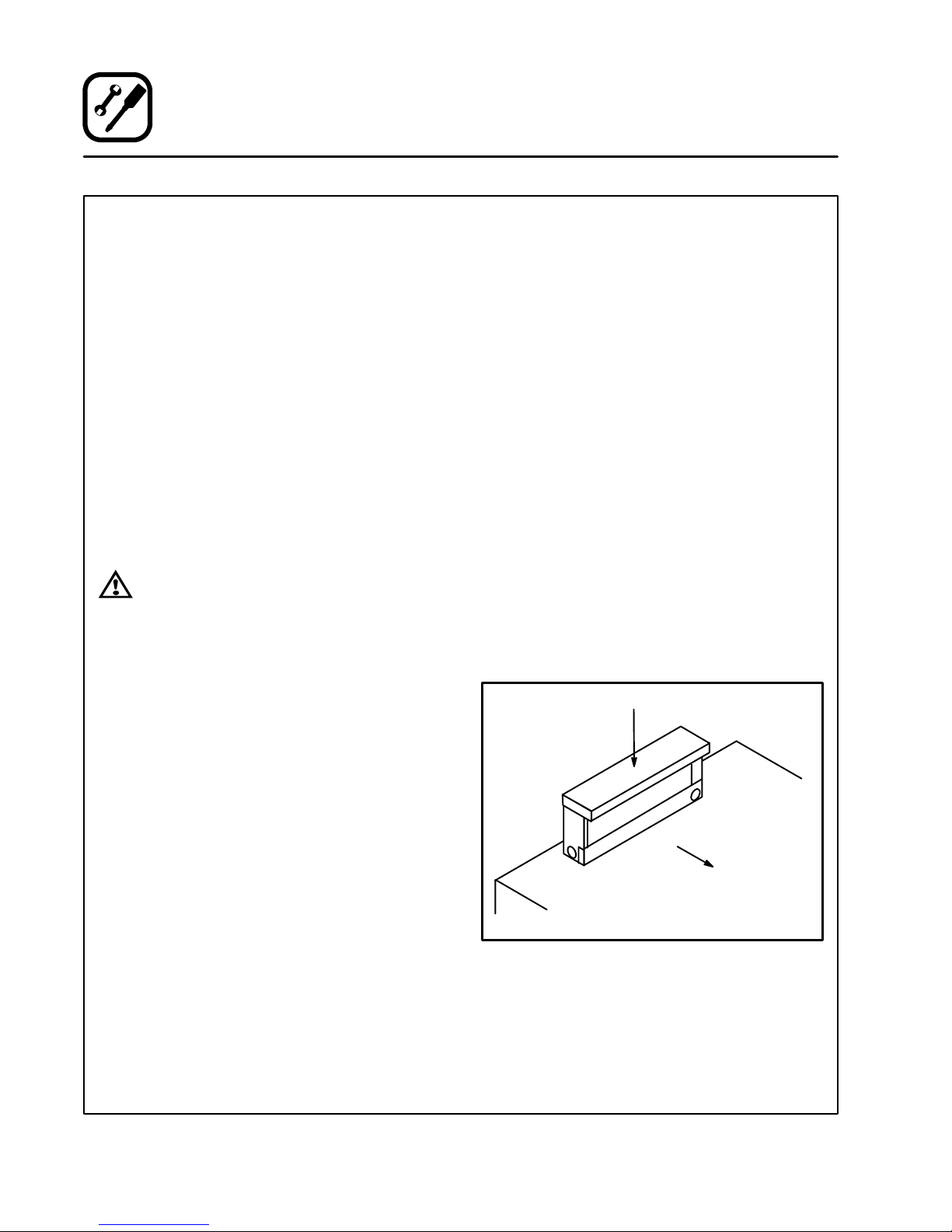
Installing the canopy hood draft diverter
Ovens ordered for hood venting are supplied with
a draft diverter.Install the draftdiverter as follows:
1. Placethe diverterover the flue connector with
theopen area facingthe front ofthe oven. See
Figure 6.
2. Secureboth endswiththe sheet metalscrews
provided.
Draft Diverter
WARNING:
Failure to properly vent the oven can be
hazardous to the health of the operator
and may result in operational problems,
unsatisfactory baking and possible damage to the equipment.
Damage sustainedas a direct resultof improper ventilation will not be covered by
the Manufacturer’s warranty.
Front of
Oven
Figure 6
8
Page 13
DIRECT FLUE ARRANGEMENT
When the installation of amechanicallydriven exhaust hoodis impractical the oven may be vented
by a direct flue arrangement.
Installation
Ventilation
Flue
WARNING!!
It is essential that the direct flue be
installed as follows. Incorrectinstallation
will result in unsatisfactory baking and
oven damage.
ThefluemustbeclassBorbetterwithadiameter
of 10” (25.4 cm). The height of the flue s hould rise
6-8ft (2-2.5m) abovetheroofofthebuilding orany
proximate structure. Never direct vent the oven
into a hood. The flue should be capped with a UL
Listed type vent cap to isolate the unit from external environmental conditions.
Thedirectventcannotreplaceairconsumedand
vented by the oven. Provisions must be made to
supply the room with sufficient make -up air. Total
make-up air requirements for each oven section
should be approximately 30 CFM per section. To
increase the supply air entering the room, a ventilation expert should be consulted.
Installing the draft hood
Ovensordered fordirect venting are suppliedwith
a draft hood. Install the draft hood as follows:
1. Place the draft hood over the flue connector.
SeeFigure7.
2. Secureboth endswiththe sheet metalscrews
provided.
Draft Hood
Front of
Oven
Figure 7
VENTING PROBLEMS
Blodgettgas deck ovens use the naturalprincipal
of heat rising as the basicmethod of ventilation. If
the venting ofany deckoven is either restricted or
forcedin any waythe baking characteristicsof the
oven w ill be adversely affected.
Examples of forced venting include:
D
installation of a fan in a direct vent pipe
D
use of a canopy type hoodwithout the draft diverter
Examples of restricted venting include:
D
use of tees and elbows
D
long horizontal runs
Insufficientmake-up air can cause heated air and
combustiblestoremain inthe oven shorteningthe
life of the components.
9
Page 14
Installation
Utility Connections --- Standards and Codes
THE INSTALLATION INSTRUCTIONS CONTAINED HEREIN ARE FOR THE USE OF QUALIFIEDINSTALLATIONANDSERVICE PERSONNEL
ONLY. INSTALLATION OR SERVICE BY OTHER
THAN QUALIFIED PERSONNEL MAY RESULT IN
DAMAGE TO THE OVEN AND/OR I NJURY TO
THE OPERATOR.
Qualified installation personnel are individuals, a
firm, a corporation, or a company which either in
person or through a representative are engaged
in, and responsible for:
D
the installation or replacement of gas piping
and the connection, installation, repair or s ervicing of equipment.
Qualified installation personnel must be experienced in such work, familiar with all precautions
required,and havecompliedwith allrequirements
of state or local authorities having jurisdiction.
U.S. and Canadian installations
Installation must conform with local codes, or in
the absence of local codes, with the National Fuel
Gas Code, NFPA54/ANSI Z223.1---Latest Edition,
the Natural Gas Installation Code CAN/CGAB149.1 or the Propane Installation Code, CAN/
CGA-B149.2 as applicable.
General export installations
Installationmust conform with Local and National
installation standards. Local installation codes
and/or requirements may vary. If you have any
questionsregarding the proper installationand/or
operation of your Blodgett oven, please contact
yourlocaldistributor.If youdo nothavea localdistributor, pleasecallthe BlodgettOvenCompanyat
0011-802-860-3700.
10
Page 15
Installation
L
t
h
p
g
Gas Connection
GAS PIPING
Aproperlysizedgas supplysystem isessentialfor
maximum oven performance. Piping should be
sized to provide a supplyof gassufficient to meet
themaximum demandof allapplianceson the line
without loss of pressure at the equipment.
Example:
NOTE: BTU values in the following example are
for natural gas.
Youpurchase a 1048-BLdeck oventoadd toyour
existing cook line.
1. AddtheBTU ratingofyourcurrentappliances.
Pitco Fryer 120,000 BTU
6 Burner Range 60,000 BTU
Convection Oven 50,000 BTU
Total 230,000 BTU
2. Add the BTU rating ofthe new ovent o the total.
Previous Total 230,000 BTU
1048-BL 85,000 BTU
New Total 315,000 BTU
3. Measure the distance from the gas meter to
the cookline. This is the pipe length.Let’ssay
the pipe length is 40’ (12.2 m) and the pipe
size is 1” (2. 54 cm).
4. Use the appropriatetable to determine the to tal capacity of your current gas piping.
The total capacity for this example is 320,000
BTU. Since the total required gas pressure,
315,000 BTU is less than 320,000 BTU, the
current gas piping will not have to be increased.
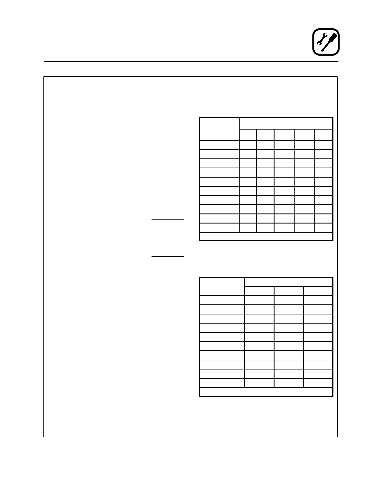
NOTE: TheBTUcapacitiesgiven in the tablesare
for straight pipe lengths only. Any elbows
orotherfittings willdecreasepipecapacities. Contactyour local gas supplier if you
have any questions.
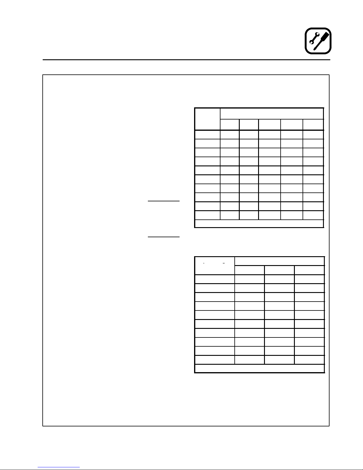
Maximum Capacity of Iron Pipe in Cubic Feet
of Natural Gas Per Hour
(Pressure drop of 0.5 Inch W.C.)
Pipe
eng
(ft)
10 360 680 1400 2100 3950
20 250 465 950 1460 2750
30 200 375 770 1180 2200
40 170 320 660 990 1900
50 151 285 580 900 1680
60 138 260 530 810 1520
70 125 240 490 750 1400
80 118 220 460 690 1300
90 110 205 430 650 1220
100 103 195 400 620 1150
From the National Fuel Gas Code Part 10 Table 10-2
Maximum Capacity of Pipe in Thousands of
BTU/hr of Undiluted P.P. Gas at 11” W.C.
(Pressure drop of 0.5 Inch W.C.)
Pipe Length
(ft)
10 608 1146 3525
20 418 788 2423
30 336 632 1946
40 287 541 1665
50 255 480 1476
60 231 435 1337
70 215 404 1241
80 198 372 1144
90 187 351 1079
100 175 330 1014
From the National Fuel Gas Code Part 10 Table 10-15
Nominal Size, Inches
3/4” 1” 1-1/4” 1-1/2” 2”
Outside Diameter , Inches
3/4” 1” 1 -1/2”
11
Page 16
Installation
Gas Connection
PRESSURE REGULATION AND TESTING
Each section of t he 1048-B series ovenis rated at
120,000 BTU per hour (35.2 kW). The 1048-BLseries ovens are rated at 85, 000 BTU per hour(24.9
kW).Atfull demand, eachsection1048-B requires
120 cubic feet per hour (3.2 m
cubic feet per hour (1.3 m
section 1048-BL oven requires 85 cubic feet per
hour(2.4 m
(0.9 m
3
)Natural gasor 33 cubicfeet per hour
3
) Propane gas. Each oven has been ad-
3
) Natural gas or 47
3
) Propane gas. Each
justedat the factorytooperate withthe type ofgas
specified on the rating plate.
Inlet Pressure
Natural Propane
Min Max Min Max
W.C. 7.0 10.5 11.0 13.0
kPa 1.43 2.61 2.74 3.23
Manifold Pressure
Natural Propane
W.C. 3.5 10.0
kPa .87 2.49
D
InletPressure --- the pressure ofthe gasbefore
it reaches the oven.
D
Manifold Pressure --- the pressure of the gas
as it enters the main burner(s).
D
Min - -- the minimum pressure recommendedto
operate the oven.
D
Max --- the maximum pressure at which t he
manufacturer warrants the oven’s operation.
Each oven issupplied with a regulator tomaintain
the propergas pressure. Theregulator is essen-
tial to the proper operation of the oven and
must be installed. It ispreset toprovide the oven
with 3.5” W.C.(0.87 kPa) for natural gas and10.5”
W.C. (2.50 kPa) for Propane at the manifold.
DO NOT INSTALL AN ADDITIONAL REGULATOR
WHERE THE OVEN CONNECTS TO THE GAS
SUPPLY UNLESS THE SUPPLY EXCEEDS THE
MAXIMUM PRESSURE.
Due to the decrease in oxygen at higher elevations, above 2000’, the unit may need to be rerated. (The orifice size mayneed to be adjusted to
accomodate different air pressures at higher
elevations.)If not rerated, incompletecombustion
mayoccurreleasingAldehydesandCOorCarbon
Monoxide. Any of these are unacceptable and
maybe hazardoustothe healthof the operator.
Prior to connecting the oven, gas lines shouldbe
thoroughly purged of all metal filings, shavings,
pipedope, and other debris. Afterconnection,the
ovenshould be checked for correct gas pressure.
Installation must conform with local codes, or in
the absence of local codes, with the National Fuel
Gas Code, NFPA54/ANSI Z223.1---Latest Edition,
the Natural Gas Installation Code CAN/CGAB149.1 or the Propane Installation Code, CAN/
CGA-B149.2 as applicable.
The oven and its individual shutoff valve must be
disconnected from the gas supply piping system
during any pressure testing of that system at test
pressuresinexcessof1/2psig(3.45kPa).
The oven must be isolated from the gas supply
piping system by closing its individual manual
shutoff valve during any pressure testing of the
gas piping system at test pressures equal or less
than 1/2 psig (3.45kPa).
12
Page 17
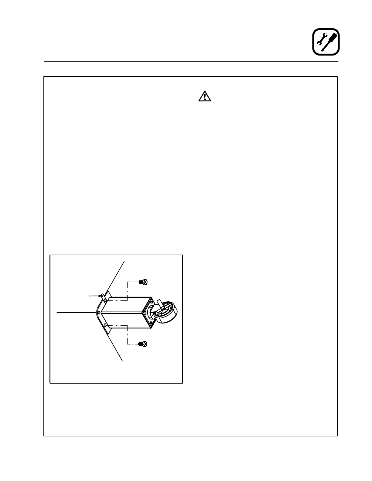
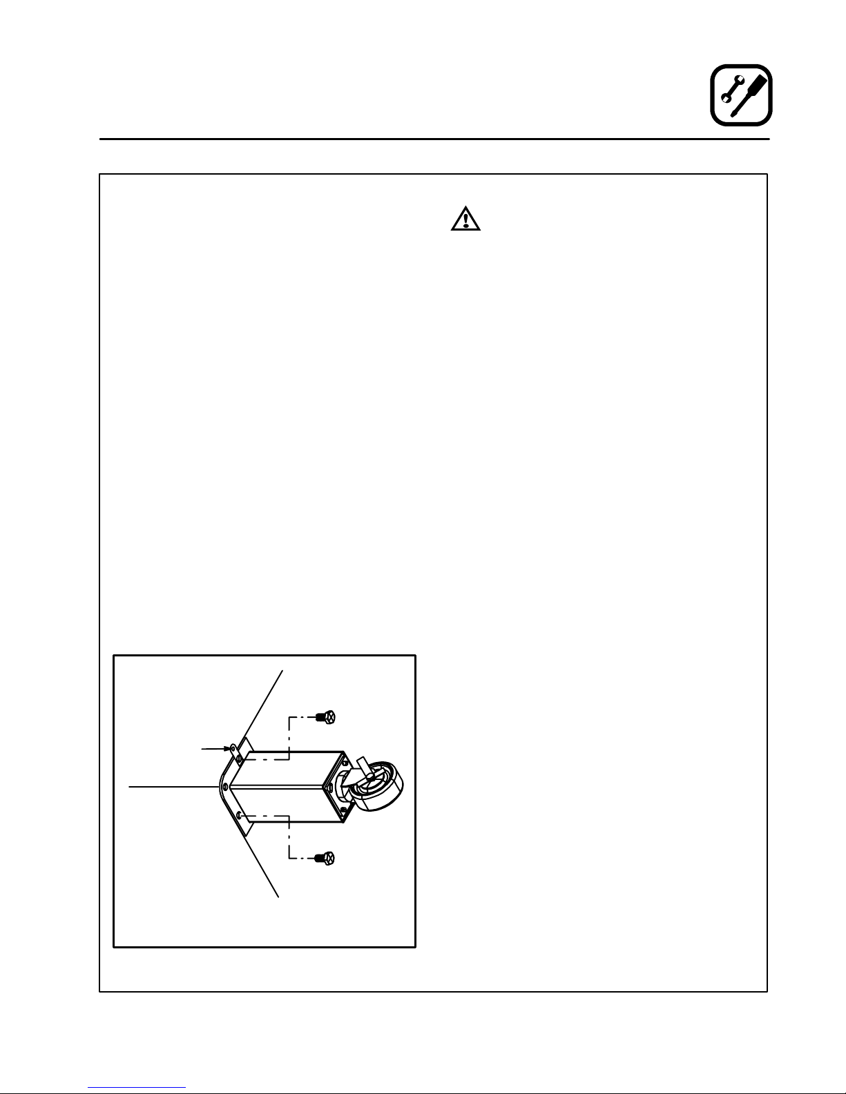
GAS HOSE RESTRAINT
If the oven is mounted on casters, a commercial
flexible connector with a minimum of3/4” (1.9 cm)
inside diameter must be used along with a quick
connect device.
The restraint, supplied with the oven, must be
used to limit the movement of the unit s o that no
strain is placed upon the flexible connector. With
the restraint fully stretched the connector should
be easy to install and quick connect.
The restraint (ie: heavy gauge cable) should be
1,000lb.(453 kg)test loadandshouldbeattached
without damaging the building. DO NOT use the
gas piping or electrical conduit for the attachment
of the permanent end ofthe restraint!Use anchor
bolts in concrete or cement block. On wooden
walls, drive hi test wood lag screws intot he studs
of the wall.
1. Mountthesupplied bracket to the leg boltjust
below the gas inlet. See Figure 8.
2. The clip on restraining cable can be attached
to the mounting bracket.
Back of Oven
Restraint
Cable Bracket
Installation
Gas Connection
WARNING!!
If the restraint is disconnected for any
reason it must be reconnected when the
oven is returned to its original position.
U.S. and Canadian installations
The connector mustcomply with the Standard for
Connectors for Movable Gas Appliances, ANSI
Z21.69 or Connectors For Moveable Gas Appliances CAN/CGA-6.16 and a quick disconnect
device that complieswith the Standard for QuickDisconnect Devices for Use With Gas Fuel, ANSI
Z21.41orQuick DisconnectFor Use With GasFuel
CAN 1-6.9. Adequate means must be provided to
limit the movement of the appliance without depending on theconnection and the quickdisconnect device or its associated piping. Adequate
means must be provided to limit the movement of
the appliance without depending on the connectiona n d thequick disconnect device or its associated piping.
General export installations
The restraint and quick connect must conform
withLocaland Nationalinstallationstandards. Local installation codes and/or requirements may
vary.Ifyouhaveanyquestionsregardingtheproper installation and/or operation of your Blodgett
oven, please contact your local distributor . If you
do not have a local distributor, please call the
Blodgett Oven Company at 0011-802-860-3700.
Double stacked unit shown. Use the same procedure for
single units with 25” (64 cm) legs.
Figure 8
13
Page 18
Operation
Safety Information
THE INFORMATION CONTAINED IN THIS SECTIONISPROVIDEDFORTHEUSEOFQUALIFIED
OPERATING PERSONNEL. QUALIFIEDOPERATING PERSONNEL ARE THOSE WHO HAVE
CAREFULLY READ THE INFORMATION CONTAINED IN THIS MANUAL, ARE FAMILIAR WITH
THE FUNCTIONS OF THE OVEN AND/OR HAVE
HAD PREVIOUS EXPERIENCE WITH THE OPERATIONOFTHEEQUIPMENTDESCRIBED.ADHERENCE TO THE PROCEDURES RECOMMENDED HEREIN WILL ASSURE THE
ACHIEVEMENT OF OPTIMUM PERFORMANCE
AND LONG, TROUBLE-FREE SERVICE.
SAFETY TIPS
For your safety read before operating
What to do if you smell gas:
D
DO NOT try to light any appliance.
D
DO NOT touch any electrical switches.
D
Use an exterior phone to callyour gas supplier
immediately.
D
If you cannot reach your gas supplier, call the
fire department.
What to do in the event of a power failure:
D
Turn all switches to off.
NOTE: In the eventof ashut-down of any kind, al-
low a five (5) minute shutoff period before
attempting to restart the oven.
General safety tips:
D
DO NOT use tools to turn off the gas control. If
thegas cannotbeturned offmanuallydo nott ry
to repair it. Call a qualified service technician.
D
If the oven needs to be moved for any reason,
the gas must be turned off and disconnected
from the unit before removing the restraint
cable. Reconnect the restraint after the oven
has been returned to its original location.
D
DO NOT remove the control cover unless the
oven is unplugged.
Please take the time to read the following operatinginstructions.Theyare thekey tothe successful
operation of your Blodgett deck oven.
14
Page 19
Operation
Oven Control
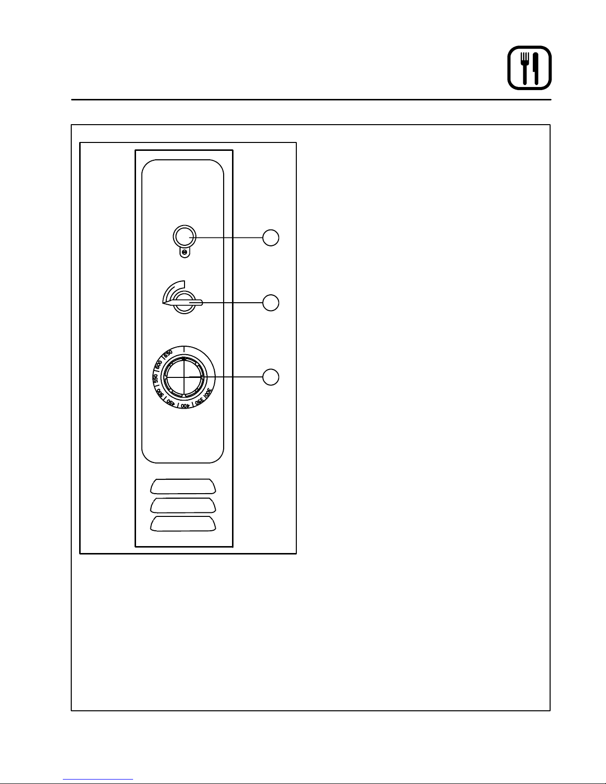
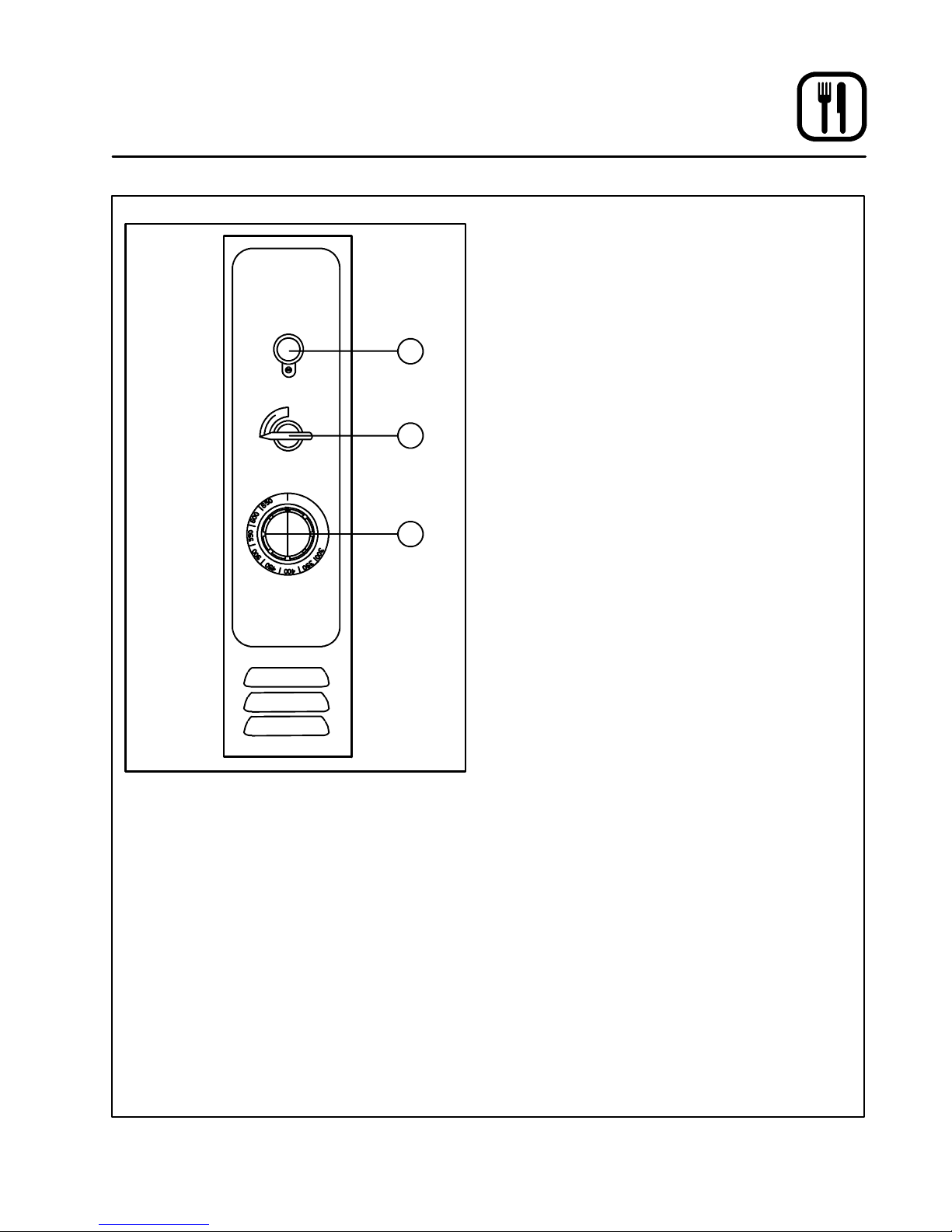
OPERATION
Theoperationof the1048 SeriesOvenisas simple
as 1, 2, 3. --- Lighting, Preheating and Loading.
Lighting
1. T urnthe MANUAL CONTROL VALVE(2) toOFF.
2. Push the red button on the AUTOMATIC
1
2
3
SAFETY PILOT VALVE (1).
3. Apply a lighted matchor taper to pilotburner.
4. After pilot burner lights, continue to depress
red button for about 30 seconds and release.
5. T urn the MANUAL CONTROL VALVE (2) to ON.
6. SetTHERMOSTAT(3)to desiredtemperature.
Preheating
1. On initial startup, preheat the oven to 600_F
(315_C) over a period of four hours in increments of 100_F(55_C) starting at 300_F
(149_C).Checkthe oven periodically. Thiswill
temper the Ultra Rokite shelves and burn off
any oil and fiberglass residue.
NOTE: The 1048 (with Ultra Rokite shelves)
will require an additional 20 minutes
onapreheatto600_F (315_C).
Loading
CONTROL DESCRIPTION
1. AUTOMATIC SAFETY PILOT VALVE --- provides complete gas shut-offin the event of pilot failure.
2. MANUAL CONTROL VALVE --- provides manual control of gas flow to the main burner
through the thermostat.
3. THERMOSTAT --- Provides regulation of oven
temperature at setting selected by the oven
operator.
Pizza in pans should be placed in rotation on the
shelf allowing it to recover its loss of temperature
fromthepreviousbake. Donotallow pans totouch
each other or sides of oven. Open doors as seldom as possible.
The deck is intended for cooking pizza and bread
products, other types of food may be cooked in
pans or containers.
To turn the oven off
1. T urn the MANUAL CONTROL VAL VE(1) to OFF.
NOTE: When the oven is shut down, place the
Main Manual Control Valve in the OFF
position. It is not necessary to extinguish
the pilot flame.
15
Page 20

Operation
General Guidelines for Operating Personnel
COOK TIMES AND TEMPERATURES
Cook Temperatures
Cook temperatures vary with different products.
Experiment with the initial bakes untilyou findthe
ideal combination of time and temperature.
Example: pizza
1. Run several bakes at 500_F (260_C). Make
note of the time required to achieve a firm
crust.
2. Ifthecheesebreaksdowntooquicklyor
scorches, lower the temperature and lengthenthebaketime.
3. If faster production is desired, run additional
bakes increasing the temperature by increments of 25_F(15_C).
4. Record the results to determine the highest
temperature at which you can bake and
achievequalityresultswith maximumproduc tion.
NOTE: Pull time is critical at high temperatures.
Cook Time
Cook times vary with the amount of product
loaded,the typeofpan andthetemperature. Raisingthe temperatureto lowerthecooktimeiseffec tive toa point.Then the quality of the bake begins
to suffer.
BAKING TIPS
D
Scale dough for consistent product.
D
Proof dough to proper consistency.
D
Refrigerated dough or pies should be brought
to room temperature before baking. Bubbles
may occur when baking refrigerated product.
Break bubbles if necessary.
D
Alternateuse between upper and lowersection
in a double oven.
D
Avoid frequent needless opening of the door
D
Rotate product placement in the oven.
16
Page 21

Maintenance
Cleaning and Preventative Maintenance
CLEANING THE OVEN
Painted and stainless steel ovens may be kept
clean and in good condition with a light oil.
1. Saturate a cloth, and wipe the oven when it is
cold.
2. Dry the oven with a clean cloth.
On the stainless front or interiors, deposits of
baked on splatter may be removed with any nontoxic industrial stainless steel cleaner. Heat tint
andheavy discoloration maybe removedwith any
non-toxic commercial oven cleaner.
1. Apply cleaners when theoven is cold, and al -
waysrubwiththegrainofthemetal.
CleanUltraRokitedeckswithatriangularscraper
used for cleaning broiler grids. IMPORTANT --
DONOTusewateroranyotherliquidstoclean
the deck!
Clean the aluminized interior portion of the oven
with a mild detergent. DO NOT use caustic solutionssuchasammonia,lyeorsodaash.DONOT
use domestic oven cleaners. Any of these products will damage the aluminum coating.
Daily Cleaning
D
Remove residue from beneath thedoors witha
small broom or brush.
Weekly Cleaning
D
Brush out the combustion compartment and
control area.
6 Month Cleaning
D
Clean secondary air ducts and air entry ports.
NOTE: If the oven is moved the restraint must be
reconnectedafter theunit isreturnedtoit’s
regular position.
PREVENTATIVE MAINTENANCE
Thebestpreventativemaintenancemeasures are,
theproper installationofthe equipmentandaprogram for routinely cleaning the ovens.
This oven requires no lubrication, however , the
venting system should be checked annually for
possibledeteriorationresultingfrom moistureand
corrosive flue products.
Ifmaintenance orrepairs arerequired,contact the
factory, the factory representative or a local
Blodgett service company.
17
Page 22
Maintenance
Troubleshooting Guide
POSSIBLE CAUSE(S) SUGGESTED REMEDY
SYMPTOM: Strong bottoms on the bakes
S
Too much bottom heat
S
High gas pressure
S
Faulty flue (strong direct vent)
S
Product left in the oven too long
SYMPTOM: Uneven bakes
S
Poor ventilation
S
Oven doors left open too long
S
Improper scaling of dough
S
Fluctuating gas pressure
S
Warped pans
S
Reduce cook temperature and increase time
S
*
S
*
S
Shorten cook time
S
*
S
Do not open door unnecessarily
S
Scale dough consistently
S
*
S
Change pans
SYMPTOM: Product burning
S
Thermostat set too high
S
Product left in the oven too long
S
By-pass flame too high
S
High gas pressure
S
Thermostat out of calibration
S
Heat deflectors worn out
*Denotes remedy is a difficult operation and should be performed by qualified personnel only.It is recommended, however, that
All repairs and/or adjustments be done by your localBlodgett service agency and not by the owner/operator.Blodgett cannot assume responsibility for damage as a result of servicing done by unqualified personnel.
S
Reduce cook temperature
S
Shorten cook time
S
*
S
*
S
*
S
*
18
Page 23
Maintenance
Troubleshooting Guide
POSSIBLE CAUSE(S) SUGGESTED REMEDY
SYMPTOM: Product dried out
S
Oven temperature too low
S
Not using enough water in the mix
S
Thermostat out of calibration
S
Faulty flue (strong direct vent)
SYMPTOM: Extended baking times
S
Temperature setting too low
S
Low gas pressure
S
Strong ventilation
S
Excessive door openings
*Denotes remedy is a difficult operation and should be performed by qualified personnel only.It is recommended, however, that
All repairs and/or adjustments be done by your localBlodgett service agency and not by the owner/operator.Blodgett cannot assume responsibility for damage as a result of servicing done by unqualified personnel.
S
Increase cook temperature
S
Increase water in product mix
S
*
S
*
S
Increase cook time
S
*
S
*
S
Do not open door unnecessarily
19
Page 24
Introduction
Description et Spécifications du Four
Lesfoursà plateforme Blodgettontétablileshauts
standardsde qualitéde l’industriepar leurscaractéristiques de cuisson au four, le rendement et la
fiabilité.Ils restentsanségalpourlaqualité duproduit.
La simplicité de conception et la qualité de leur
constructionjusque dans les moindres détailsas-
Gaz Naturel Gaz Propane
Unités US Unités SI Unités US Unités SI
1048-BL SPECIFICATIONS POUR GAZ
Valeur de Chauffe 1000 BTU/hr 37.3 MJ/m
Gravité Specifique (air=1.0) 0.63 0.63 1.53 1.53
Pressionarrivéede gazau
collecteur
Consommation Four
Par brûleur
Par four
Brûleur principal taille orifice 30 MTD* 3.3 mm 48 MTD* 1.93 mm
3.5” W. C. 0.87 kPa 10” W.C. 2.49 kPa
42,500 BTU/hr
85,000 BTU/Hr
surent des années de service sans problème
quand l’équipement est correctement installé et
entretenu.
Lescaractéristiques comprennentun bâtientièrementen fer enL,des rayons d’anglesentièrement
soudéset, un avant et des portes en acier inoxydable.
3
12.4 kW
24.9 kW
2550 BTU/hr 95.0 MJ/m
42,500 BTU/Hr
85,000 BTU/Hr
12.4 kW
24.9 kW
3
Brûleur veilleuse taille orifice .018” Dia. .46 mm .010” Dia. .25 mm
1048-B SPECIFICATIONS POUR GAZ
Valeur de Chauffe 1000 BTU/hr 37.3 MJ/m
Gravité Specifique (air=1.0) 0.63 0.63 1.53 1.53
Pressionarrivéede gazau
collecteur
Consommation Four
Par brûleur
Par four
Brûleur principal taille orifice 23 MTD* 3.9 mm 44 MTD* 2.18 mm
Brûleur veilleuse taille orifice .018” Dia. .46 mm .010” Dia. .25 mm
REMARQUE:*Mèche hélicoïdale multiple
Specifications fournies en unités US et SI
3.5” W. C. 0.87 kPa 10” W.C. 2.49 kPa
60,000 BTU/hr
120,000 BTU/Hr
17.6 kW
35.2 kW
3
2550 BTU/hr 95.0 MJ/m
60,000 BTU/Hr
120,000 BTU/Hr
17.6 kW
35.2 kW
3
20
Page 25
Introduction
Éléments du Four
Plateforme de Rokite --- plateforme de pierrequi
absorbe la chaleur du bas du four pour cuire le
dessous du produit.
Plateforme d’acier --- qui a bsorbe la chaleur du
bas du four pour cuire le dessous du produit.
Supports de plateforme --- supportent les plateformes du four.
Joint d’étanchéité de la plateforme --- bouche
l’espace entre la plateforme et l’avant du four.
Panneau de Contrôle --- contient les câblages et
les éléments permettant de contrôler le fonctionnement du four.
Compartiment des brûleurs --- situé au --- des sousde la chambre de cuisson.Ce compartiment
contient les brûleurs à combustion directe.
Brûleurs à combustion directe --- fournissent la
chaleur à la chambre de cuisson et aux plateformes.
Déflecteur --- détourne une partie de la chaleur
des brûleurs à combustion directe vers les
plaques tubulaires.
Plaques tubulaires --- situées sur les parois intérieuresdela chambre de cuisson. Les plaquestu bulaires conduisent la chaleur des brûleurs à la
cavitédu four. Lachaleur cuit ledessus du produit
avant d’être évacuée du four.
Plaques tubulaires
Plateforme
Panneau de
Contrôle
Compartiment
des brûleurs
Compartiment
de cuisson
Joint d’étanchéité
de la plateforme
Figure 9
21
Page 26

Installation
Livraison et Implantation
LIVRAISON ET INSPECTION
Tous les fours sont expédiés en conteneurs. A la
réception de votre four Blodgett vous devez:
D
Vérifierque les emballagesne sontpas abimés.
Toute défection dans l’emballage doit être notée sur l’accusé de reception de la marchandise; celui-ci doit être signé par le chauffeur.
D
Sortir le four de son emballage et vérifier son
bon état. Les transporteurs n’acceptent les réclamations et plaintes que si elles sont faites
dans les quinze jours qui suivent la livraison et
sil’emballage a été conservéafin d’être inspecté.
La Blodgett Oven Co., n’est pas responsable
des dégâts subis pendant le transport. Le
transporteur est seul responsable de la livraison du matériel en bon état lorsque l’expédi tiona été acceptée. Néanmoins, noussommes
àvotredisposition pour vousaider à composer
votre dossier de réclamation.
IMPLANTATION DU FOUR
L’implantation correcte et bien étudiée du four
seraàl’avantageàlongtermedel’opérateuret
permettra d’obtenir un rendement satisfaisant.
Lesespaces de dégagement ci---dessousdoivent
êtreprévusentre lefourettouteconstructioncombustible ou non.
D
Côté droit du four - -- 15 cm
D
Côté gauche du four --- 15 cm
D
Arrière du four --- 15 cm
D
Dessous du four --- 15 cm
Les espaces de dégagement ci-dessous doivent
être possible pour permettre l’entretien.
D
Côté gauche du four --- 30.5 cm
REMARQUE:L’entretien régulier peut en général
être effectué dans les limites du déplacement que permet la chaîne de
retenue. Si le four doit être plus écarté du mur, l’alimentation en gaz doit
être coupée et la canalisation débranchée du four avant d’enlever la
chaîne.Celle-cidoit êtreutiliséepour
empêcher d’exercer toute contrainte
surlecoupleurdegaz.
Il est essentiel qu’une circulation d’air adéquate
aufoursoit maintenuepourapporterundébit d’air
de combustion et de ventilation suffisant.
D
L’emplacement ne doit pas avoir de courants
d’air.
D
Maintenez la zone du four libre et dégagée de
tous matériaux combustibles telsque lepapier,
le carton, ainsi que les liquides et solvants inflammables.
D
Lefournedoit pasêtre placésurunesurfaceincurvéeoufixéau mur. L’empêcherait l’airde circuler librement vers le compartiment de combustion et par conséquent produirait une
mauvaiseventilation.L’extinctionde laveilleuse
ou des flammes jaunes provenant du brûleur
principal indiquent un manque d’arrivée d’air
secondaire.
D
Lefour doitêtre installésurlespieds fournispar
le fabricant.
Veuillez vérifier le tableau de spécifications avant
d’effectuer tout branchement sur ce four afin de
vous assurer ques les spécifications de ce four
sont compatiblesavec le gaz d’arrivée au four. Le
tableaudespécificationssetrouveàl’intérieurde
la porte du compartiment brûleur. Il faut ouvrir la
portepourletrouver.
22
Page 27

Installation
Montage du Four
EMBALLAGE
Avantde commencerlemontagedu fouril fautvérifier que tous ses composants sont présents. En
plus du four, lui-méme, il faut des pieds, un
systèmedeventilationet/ou d’autresaccessoires.
Pourlessectionssimples:
1048 avec des plaques en metallique
D
Des pieds, une régulateur, un collet de tuyau,
un diverteur d’air et des plaques en metallique
sontemballésdanslefour.
D
Une hotte à air (quand elle est fournie) est emballés dans une boîte individuelle.
1048 avec des plaques en Rokite
D
Despieds, une régulateur, un colletde tuyau, et
un diverteur d’air sont emballés dans le four.
D
Des plaques en Rokite sont emballés dans une
boîte individuelle.
D
Une hotte à air (quand elle est fournie) est emballés dans une boîte individuelle.
Pourlessectionsdoubles:
1048 avec des plaques en metallique
D
Des pieds et boulons, une régulateur, un collet
de tuyau, un raccordement de tuyau pour four
double et des plaques en metallique sont emballés dans la section du bas.
D
Une régulateur, un collet de tuyau et des
plaques, un diverteur d’air, en metallique sont
emballésdanslasectionduhaut.
D
Lecadredepiedd’angle estemballés dansune
boîte individuelle.
D
Une hotte à air (quand elle est fournie) est emballés dans une boîte individuelle.
Double 1048 avec des plaques en Rokite
D
Des pieds et boulons et un raccordement de
tuyau pour four double sont emballés dans la
sectiondubas.
D
Unerégulateur,undiverteur d’air,et uncolletde
tuyausontemballésdanslasectionduhaut.
D
Les plaques en Rokite sont emballées dans
deux boites en carton séparées.
D
Lecadredepiedd’angle estemballés dansune
boîte individuelle.
D
Une hotte à air (quand elle est fournie) est emballés dans une boîte individuelle.
ASSEMBLAGE DES PIEDS
2. Pousserle four, couché sur ledos, s ur unélévateur.
3. Chaque piedest fixépar troisboulonssous la
base du four.
FIXATION DES ROULETTES
1. Boulonnez les supports à celui-ci au moyen
de boulons de 1/2-13 à tête hex (les roulettes
freinées doivent être tournées vers le devant
du four).
2. Faites reposer avec précaution le four sur les
roulettes.(Ilseranécessaire dele fairesoulever de la palette et de le faire reposer sur les
roulettespar plusieurspersonnes.) Serrez les
freinsdesroulettesavant.
REMARQUE:Un dispositif de retenue fixe doit être
fourni si des roulettes sont utilisés
avecun connecteur flexible pour des
appareilsportatifs. Ce dispositif doit
fixerlefouràunesurfaceimmobile
pour éliminer toute contrainte pouvant être subie par le connecteur. Si
le four est déplacé, il faut rebrancher
le connecteur après avoir remis le
four en position normale.
23
Page 28
Installation
Montage du Four
MONTAGEDELASECTIONDOUBLE
1. Fixerlespieds de12” (305mm) àla sectiondu
bas.
2. Retirerlagaine de métal qui recouvre letuyau
aubasde laSECTIONSUPERIEUREDUTUYAU SEULEMENT et conserver les deux vis.
3. Attacherle cadredepied d’anglede ragrandir
aux sections supérieures.
4. Insère le four double connection de tuyau en
la section supérieure de four tuyau jusqu’à lui
estnettoyage avecl’angle de base. Tienttemporairement dans l’endroit avec la bande.
5. Installer la section du haut sur la section du
bas.
6. Enlever la bande et diapositive la connection
detuyauenlapositionsurlecoldelasection
du bas. Voir Figure 10.
7. Attacher laconnectiondu tuyau au sectiondu
bas avec des vis du tuyau couverture.
8. Monter la hotte à air ou le diverteur d’airavec
les vis fournies.
MONTAGE DU DÉFLECTEUR EN TROIS
PARTIES
1. Les déflecteurs sont expédiés en place dans
le four. Leur montage n’est pas nécessaire.
2. Retirerla patted’attachement quise trouveau
centrearrièredechaquedéflecteuravantd’insérer l’ensemble fait de deux-parties de la
plaque.
DES PLAQUES EN ROKITE
1. Saisir la plaque en Rokitedans l’ouverturede
la porte. La glisser par l’ouverture de la porte
versl’arrièredu four jusqu’à ce qu’ elle repose
la plaque sur le support de plaque. La glisser
vers ladroitjusqu’àce qu’elle tombe en place.
2. Glisser l’une des deux plaques étroites par
l’ouverturede laporetevers l’arrière del’autre
plaque jusqu’à ce qu’ elle soit dans le support
de plaque. La glisser vers la gauche jusqu’à
ce qu’elle tombe en place.
3. Presserlesdeuxparties deplaquesversl’intérieur de telle sorte que lesjoints se ferment.
4. Référer à pre-chauffage instructions approvisionnèes avec Rokite.
REMARQUE:Acausedupoids desplaquesenRo-
kite, faites attention de ne pas vous
blesseroud’abîmer lesplaqueslorsque vous les faites glisser dans le
four.
Figure 10
Figure 11
24
Page 29

Installation
Montage du Four
JOINT DE PLAQUE
1. Placer la partie longue de la lèvre du joint devant l’angle de support du plateau. Placer la
partie courte de la lèvre qui a des encoches
entre l’angle du support de plaque et la
plaque.
2. Pousser vers le bas dand son emplacement.
Figure 12
PLAQUES DE CHEMINÉE
1. Insérer l’arrière de la plaque de cheminée
dans la glissière verticale située à l’arrière du
compartiment du cuisson.
2. Pousserla plaquevers l’extérieur en direction
de la paroi latèrale du four.
3. Souleverl’extrémité avantde la plaque de 1/2
pouce afin de permettre aux deux pattes situées sur les plaque de s’aligner et de s’engager dans les glissières situées sur la paroi
avant du four.
4. Laisser retomber la plaque dans son emplacement.
MISE À NIVEAU DES FOURS
Lesfourssontéquipésde piedsajustablessuivant
le code NSF.
1. Mettre les fours à niveaulatéralement etverti calement en plaçant le niveau sur la surface
de la section inférieure.
2. Faire les réglages suivant le besoin.
RÉGLAGES À FAIRE LORS DE
L’INSTALLATION INITIALE
Chaque four ainsi que ses composants ont été
soigneusement testés et inspectés avant d’être
expédiés. Cependant, ilest bien souvent nécessaire de faire des vérifications et des réglages sur
place au moment de l’installation initiale. Ceci est
un procédé normal. De tels réglages sont sous la
responsabilitédu vendeuroudel’installateuret ne
sont pas imputables à des défauts de fabrication
ou de matériau. Par conséquent, ces réglages ne
sont pas couverts par la garantie de l’équipment
d’origine. Ces réglages comprennent, sans s’y
limiter:
D
le calibrage du thermostat
D
le réglage des portes
D
réglage du brûleur
D
la mise de niveau
D
la vérification de la pression du gaz
D
le serrage des boulons
On ne peut considérer une installation achevée
tantqu’un personnelqualifién’a pasprocédé à sa
vérificationcomplèteet faitlesréglagesnécessaires s’il en est besoin.
Figure 13
25
Page 30
Installation
Ventilation
Un système de ventilation planifié et installé est
absolumentnécessaire car il permet un bonfonctionnementdu fourtout en débarassant la surface
de travail des buées et résidus de combustion.
Il y a deux méthodes de ventilation acceptables
pour le four:
D
Soit une hotted’évacuation, de typevoûte mécanique.
D
Soit une installation à prise directe.
Installation aux États--Unis et au Canada
Se reporter aux codes locaux de laventilation. En
l’absence de codes locaux, se reporter au code
national de la ventilation intitulé ”Normes pour
l’installation d’équipements pour l’enlèvement
des fumées et vapeurs grasses provenant d’équipements commerciaux pour la cuisine”,
NFPA --- 96 --- Édition la plus récente.
AVERTISSEMENT:
Un mauvais système d’aération peut
aboutir à un mauvais fonctionnement du
four, des résultats de cuisson peu satisfaisants;il peutégalement abîmer l’appareil.
Lesdégâtscausésparune mauvaiseventilation ne sont pas couverts par la garantie du fabricant.
HOTTED’ÉVACUATIONTYPEVOÛTE
Laméthode de ventilation la meilleure est cellequi
utiliseunehotte de ventilationadéquate àmécanique.
Lahotte doitêtre conçue pour couvrirla totalitéde
l’appareil à ventiler avec en plus un surplomb se
15 cm (6”) de chaquecôté de l’appareil nonadjacent au mur. La distanceduplancher à l’extremité
laplusbasse delahottenedoitpas dépassers ept
2.1m (7’).
Le volumetotald’air neuf et d’ évacuation à consi-
dérer lors de la détermination de la capacité de
hotte nécessaire est d’environ 11 CFM pour chaque section de four.
Installation du déviateur de tirage
Les fours commandés pour hotte d’évacuation
sont fournis avec un déviateur de tirage. Installer
le déviateur de tirage comme suit :
1. Placer le déviateur au-dessus du connecteur
de cheminée avec la partie ouverte tournée
vers l’avant du four. Voir Figure 14.
2. L’assujettir des deux côtés avec les vis à tôle
fournies.
Divertisseur d’air
Avant du
four
Figure 14
26
Page 31

EN PRISE DIRECTE
Quandl’installationd’une hotte aspirantemécanique est impossible ou peu pratique à réaliser, on
peutventilerlefourau moyend’uneinstallationen
prise directe.
AVERTISSEMENT!!
Quand on utilise un système à prise di-
recte ilfaut absolument suivre le schéma.
Une installation de ventilation à prise directequi est défectueuse donnera des résultats de cuisson peu satisfaisants et
causera des dégâts prématurés aux éléments brûleurs.
La cheminée doitêtre de classe B ou mieux avec
un diamètre de 25.4 cm (10”). La ha uteur de la
cheminée doit dépasser de 2 à 2,5 m (6---8’) le
hautdutoit dubâtiment ouautre structureproche.
Ne jamais diriger la ventilation du four dans une
hotte.La cheminéedoit êtrechapeautée avecune
coiffede typehomologuéUL,pourisolerlacheminée des intempéries extérieurs.
Dans ce cas îl est important de fournir assez d’air
secondaire car l’installation à pris directe ne peut
pas renouveler l’air absorbé et ventilé par le four.
Le volumetotald’air neuf et d’ évacuation à considérer lors de la détermination de la capacité de
hotte nécessaire est d’environ 30 CFM pour chaque sectionde four.Pouraugmenter lacirculation
d’air dans la pièce, un expert en ventilation doit
être consulté.
Installation de la hotte de tirage
Les four commandés pour la ventilation directe
sont fournis avec une hotte de tirage. Installer la
hotte de tirage comme suit :
1. Placer la hotte de tirage au---dessus du connecteur de cheminée. Voir Figure 15.
2. L’assujettir des deux côtés avec les vis à tôle
fournies.
Installation
Ventilation
Cheminée
Hotte de
tirage
Avant du
four
Figure 15
PROBLÊMES DE LA VENTILATION
La Série 1048 utilise le principe naturel de la chaleur montante comme base de sa ventilation. Si
par n’importe quel moyen l’on restreint ou l’on
force la ventilationdes fours del la Série 1048, les
caractéristiques de cuisson du four seront défavorablement affectées.
Par exemple: ventilation forcée
D
l’utilisation d’un ventilateurdans letuyau àprise
directe
D
l’installation sur le four d’une hotte d’ aération
qui n’est pas installée avec lediverteur d’air en
formedeL
Par exemple: ventilation restreinte
D
des tés et coudes
D
des sections horizontales
Un air d’appoint insuffisant peut être cause que
l’airchaudetlescombustiblesrestentdanslefour,
réduisant la durée utile des composants.
27
Page 32
Installation
Branchements de Service --- Normes et Codes
LES CONSEILS D’INSTALLATION ET D’ENTRETIEN CONTENUS DANS CE MANUEL NE
S’ADRESSENT QU’Á UN PERSONNEL QUALIFIÉ. UN PERSONNEL NON QUALIFIE PEUT SE
BLES SER ET/OU ABÎMER LE FOUR LORS DE
SON INSTALLATION ET/OU SON ENTRETIEN.
Un personnel d’installationqualifié est représenté
soit par des personnes physiques, soitpar un société, une usine, une corporationquienpersonne
oupar l’intermédiaire d’un représentant s’engage
à et est responsable de:
D
l’installation oule remplacementdeconduits de
gaz, ou le branchement, l’installation, la réparation ou l’entretien de l’équipement.
Lepersonneld’installationqualifiédoit êtreexpérimentédanscetypedetravail,s’êtrefamiliarisé
avec toutes les précautions requises etrespecter
tous les réglements promulgués par les autorités
provinciales ou locales compétentes.
Installation aux États--Unis et au Canada
Les branchements de gaz doivent être en accord
avec les codes locaux, ou enl’absence de codes
locaux, avec le Code National du Gaz de Chauf-
fage, ANSI Z223.1 le Code d’Installation du Gaz
NaturelCAN/CGA-B149.1oule Coded’Installation
du Propane CAN/CGA-B149.2 si applicable.
28
Page 33
Installation
d
i
t
g
Branchement de Gaz
CONDUIT DE GAZ
Un système d’alimentation en gaz de bon calibre
est essentiel pour obtenir le meilleur rendement
du four. Les conduits doivent être calibrés pour
fournir suffisamment de gaz pour alimenter tous
lesappareilssurle conduitsans pertedepression
à l’équipement.
Exemple:
REMARQUE:Lesvaleursen BTU de l’exemple sui-
vant sont pour le gaz naturel.
Achat d’un fouràconvection 1048-BLquidoit être
ajouté sur la conduite de cuisson existante.
1. Additionnerlesvaleursnominalesen BTUdes
appareils utilisés.
Friteuse Pitco 120,000 BTU
Cuisinière 6 brûleurs 60,000 BTU
Four 50,000 BTU
Total 230,000 BTU
2. À ce total, ajouter la valeur nominale en BTU
du nouveau four.
Total précédent 230,000 BTU
1048-BL 85,000 BTU
Nouveau total 315,000 BTU
3. Mesurerla distanceentre lecompteurà gazet
la conduite de cuisson. Ceci est la longueur
de tuyau.Disons que lalongueur de tuyauest
de 12,2 mètres (40’) et le calibre du tuyau est
de 2,54 cm (1”).
4. Se reporter au tableau approprié pour déterminerlacapacitétotaledelaconduitedegaz
actuelle.
Pour cette exemple, la capacité totale est de
320,000 BTU, la conduite de gaz a ctuelle n’a
pas besoin d’être augmentée.
REMARQUE:Les capacités en BTU données sur
les tableaux sont uniquement pour
des longueurs droites de tuyaux.
Touslescoudesetautresraccords
diminuent la capacités de la conduite. Pour toute autre question,
prendre contact avec la compagnie
locale de distributiondu gaz.
Maximum Capacity of Iron Pipe in Cubic Feet
of Natural Gas Per Hour
(chute de pression de 13 mm (0,5 po)
à la colonne d’eau)
Longeur
econdu
pieds
10 360 680 1400 2100 3950
20 250 465 950 1460 2750
30 200 375 770 1180 2200
40 170 320 660 990 1900
50 151 285 580 900 1680
60 138 260 530 810 1520
70 125 240 490 750 1400
80 118 220 460 690 1300
90 110 205 430 650 1220
100 103 195 400 620 1150
Du Code national du gaz carburant Partie 10 Tableau 10-2
Maximum Capacity of Pipe in Thousands of
BTU/hr of Undiluted L.P. Gas at 11” W.C.
(chute de pression de 13 mm (0,5 po)
Longeur de
conduit pieds
10 608 1146 3525
20 418 788 2423
30 336 632 1946
40 287 541 1665
50 255 480 1476
60 231 435 1337
70 215 404 1241
80 198 372 1144
90 187 351 1079
100 175 330 1014
Du Code national du gaz carburant Partie 10 Tableau 10-15
Dimensions nominales
3/4” 1” 1-1/4” 1-1/2” 2”
à la colonne d’eau)
Diamètre extérieur
3/4” 1” 1-1/2”
29
Page 34
Installation
Branchement de Gaz
RÉGLAGEETTESTDEPRESSION
Chaque section des fours de 1048-B est standar diséeà120, 000 BTUpar heure(35.2 KW).Chaque
section des fours de 1048-BL e st standardisée à
85,000 BTU par heure (24.9 KW). Pour des fours
1048-B, il est indispensable d’avoir un systèm
d’arrivée de gaz naturel de 120 pieds cubiques
(3.40m
(1.33m
3
) ou de gaz propanede 47 pieds cubique
3
) pour alimenter chaque unité par heure
afin que le four fonctionne correctement à plein
rendement. Pour des fours 1048-BL, il est indispensabled’avoir un systèm d’arrivéede gaz naturel de 85 pieds cubiques (2.40m
pane de 33 pieds cubique (0.9m
3
)oudegazpro-
3
).Tous les fours
sont réglés en usine en fonction du type de gaz
spécifié sur la plaque signalétique.
Pression à l’entrée
Gaz Naturel Gaz Propane
Min Max Min Max
W.C. 7.0 10.5 11.0 13.0
kPa 1.43 2.61 2.74 3.23
Pression au collecteur
Gaz Naturel Gaz Propane
W.C. 3.5 10.0
kPa .87 2.49
D
Pression à l’entrée --- Pression du gaz d’arri vée, avant l’entrée du four.
D
Pression au Collecteur --- Pression du gaz à
l’entrée du ou des brûleurs principaux.
D
Min --- Pression recommandéepourlefonctionnement du four.
D
Max --- Pression maximaleà laquellelefabricant
garantit le fonctionnement du four.
Pourmaintenir la bonne pressionde gaz, chaque
four est livré avecun régulateur. Le régulateur est
essentielpourlefonctionnementcorrect dufouret
il ne doit pas être retiré. Il est préréglé pour alimenterlefouravec unepressiondegaznaturel au
collecteur de 0,87 kPa (3,5” WC [à la colonne
d’eau]) et une pression de propane au collecteur
de 2,50 kPa (10,5 WC).
NE PAS INSTALLER DE RÉGULATEUR SUPPLÉMENTAIRE OÙ LE FOUR SE CONNECTE SUR
L’ALIMENTATIONDEGAZSAUFSILAPRESSION
D’ENTRÉE EST AU-DESSUS DU MAXIMUM.
Àcausede lararéfactionde l’oxygèneàdesélévations supérieures à600 mètres, la capaciténominale de l’unité peut nécessiter une réévaluation.
(La dimension de l’orifice peut nécessiter un
ajustementpour s’accomoder des pressionsd’air
différentes à de plus hautes altitudes). Si elle n’est
pas réévaluée, une combustion incomplète peut
se produire dégageant des aldéhydes et du CO
oudel’oxydedecarbone. Aucunde cesdégage-
ments n’est acceptable etils peuventêtre dangereux pour la santé de l’utilisateur.
Avantle raccordement dufour,veillezà bien purgerles conduites degazdetoutes rognuresmétalliques, limaille, bavures d’enduit et autres débris.
Aprèsleraccordement, vérifiezla pressiondugaz.
Les branchements de gaz doivent être en accord
avec les codes locaux, ou enl’absence de codes
locaux, avec le Code National du Gaz de Chauf-
fage, ANSI Z223.1 le Code d’Installation du Gaz
NaturelCAN/CGA-B149.1oule Coded’Installation
du Propane CAN/CGA-B149.2 si applicable.
Lefouretsa vanne d’arrêtindividuelledoiventêtre
déconnectésdusystèmed’alimentationen casde
test des conduites à pression manométrique supérieure à 1/2 psi(13.85 poà la colonne d’eau ou
3.45 kPa).
Encasde testàpressionmanométriquede1/2psi
(13.85 po à la colonne d’eau ou 3.45 kPa) ou
moindre, le four doit être isolé du système par la
fermeture de sa vanne d’arrêt manuelle individuelle.
30
Page 35
RETENUE DU TUYAU DE GAZ
Si le four est monté sur roulettes, un connecteur
commercial flexible ayant un diamètre intérieur
minimum de 1,9 cm (3/4”) doit être utilisé avec un
dispositif de connexion rapide.
Laretenue, fournieavec lefour,doitservirà limiter
les mouvements de l’unité de façon qu’aucune
tension ne soit placée sur le connecteur flexible.
Quandlaretenue estentièrement étendue,le connecteurdoit êtrefacileà installeret àconnecter rapidement.
Cedispositif (qui consiste en un câble de gros calibre) doit supporter une charge d’épreuve de
1,000 lb. (453 kg) et doit être accroché au mur
pour empêcher d’endommager celui-ci. NE vous
servez PAS de la canalisation de gaz ni d’une
canalisation d’électricité pour y accrocher l’extrémitéfixéeàdemeuredudispositifderetenue!Servez-vous de boulonsd’ a ncrage dans le béton ou
les parpaings. Sur les murs en bois, utilisez des
tire-fond à bois à résistance élevée que vous enfoncez dans les montants du mur.
1. Monter la cornière fournie sur le boulon du
piedjuste au-dessousde l’arrivéede gaz. Voir
Figure 16.
2. Fixer l’attache sur le câble de retenue sur la
cornière.
Installation
Branchement de Gaz
AVERTISSEMENT!!
Si la retenue est déconnectée, quelqu’en
soit la raison, elle doit être reconnectée
quandle four estremisà sa positiond’origine.
Installations aux États--Unis et au Canada
Le coupleur doit être conforme à la Norme Applicable aux Coupleurs pour Appareils à Gaz Mobiles, ANSI Z21.69 ou Coupleurs pour Appareils à
Gaz Mobiles CAN/CGA-6.16.Ilconvientd’utiliser
égalementun dispositifdedébranchement rapide
conformeà laNormeApplicableauxDispositifsde
Débranchement Rapide pour Combustibles Gazeux, ANSI Z21.41 ou Dispositifs de Débranchement Rapide pour Combustibles Gazeux CAN
1-6.9. Une entrave fixée à une surface immobile
doitêtre prévue pour limiterle mouvement dufour
et éviter les tensions au niveau du connecteur.
Arrière du four
Cornière de retenue
du câble
Unité à deux fours superposés montrée.
Utiliser le même procédé pour les unités simples avec
des pieds de 64 cm (25”).
Figure 16
31
Page 36

Utilisation
Information de Sécurité
LES INFORMATIONS CONTENUES DANS
CETTE SECTION SONT DESTINÉES AU PERSONNEL QUALIFIÉ APPELÉ A UTILISER LE
FOUR. ONENTEND PAR PERSONNEL QUALIFIÉ
LE PERSONNEL QUIAURA LU ATTENTIVEMENT
LES INFORMATIONS CONTENUES DANS CE
MANUEL, CONNAIT BIEN LES FONCTIONS DU
FOUR ET/OU POSSEDE UNE EXPÉRIENCE ANTÉRIEURE DE L’EMPLOIDE L’ÉQUIPEMENTDÉCRIT. LE RESPECT DES PROCÉDURESRECOMMANDÉESDANS CET TE SECTIONPERMETTRA
D’ATTEINDRE LES PERFORMANCES OPTIMALES DU SYSTEME ET D’EN OBTENIR UN
SERVICE DURABLE ET SANS ENCOMBRES.
CONSEILS DE SÉCURITÉ
Pour la sécurité, lire avant d’utiliser l’ap-
pareil.
Quefaires’ilyauneodeurdegaz:
D
NEPASessayerd’allumerl’appareil.
D
NE PAS toucher d’interrupteur électrique.
D
Utiliserun téléphoneextérieur pour appelerimmédiatement la compagnie du gaz.
D
Sila compagnie du gaz nerépond pas, appeler
les pompiers.
Que faire en cas de panne de secteur:
D
Fermer tous les interrupteurs.
REMARQUE:Dans le cas d’un arrêt de l’appareil,
quel qu’il soit, attendre cinq (5) minutes avant de remettre le four en
marche.
Conseils généraux de sécurité:
D
NEPAS utiliserd’outil pour fermerlescommandes du gaz. Si le gaz ne peut pas être fermé
manuellementnepastenter deréparer.Appeler
un technicien de service qualifié.
D
Sile four doit être déplacé, quelqu’en soit laraison, legaz doit être fermé etdéconnecté de l’unitéavant de retirer le câble de retenue. Reconnecterlaretenuequandlefoura étéremis àson
emplacement d’origine.
D
NE PAS retirer le couvercle du panneau de
contrôle sauf si le four est débranché.
Prenez le temps de lire attentivement les instructionsquisuivent.Vousyt rouverez laclédusuccès
du four à Blodgett.
32
Page 37
Utilisation
Les Commandes du Four
Allumage
1. Placer la VALVE PRINCIPAL À COMMANDE
MANUEL (2) dans la position OFF.
2. Appuyer sur le bouton rouge de la VALVE DE
VEILLEUSE AUTOMATIQUE (1).
3. Placer une allumette ou une bougie allumée
1
2
3
près de la veilleuse.
4. Une fois la veilleuse allumée, continuer à appuyersur le boutonrouge pendant environ30
secondes puis relacher la pression.
5. Tourner la VALVE PRINCIPAL À COMMANDE
MANUEL (2) sur la position ON.
6. Régler le THERMOSTAT (3) à la température
voulue.
Préchauffage
1. Le premier préchauffage du four doit se faire
à une température de 315_C (600_F) sur une
périod de quatre heures en augmentant de
55_C (100_F) et en commençant à 149_C
(300_F).Ouvrirlefourdetempsentemps
pour en vérifier sa bonne marche ce qui permet en même temps de tempérer lesplaques
en Rokite et de brûler les graisses et résidus
de fibre de verre.
REMARQUE:Le four avec plaque en Rokite à
une tempéra tu re de préchauffa ge
de 315_C (600_F) a besoin plus
20 minutes de préchauffage.
Chargement
DESCRIPTION DES COMMANDES
1. LAVALVEDEVEILLEUSEAUTOMATIQUE--fermetoutearrivéedegazlorsquelaveilleuse
ne fonctionne pas.
2. LAVALVEPRINCIPALEACOMMANDEMANUELLE --- procure une commande manuelle
de l’arrivée du gaz au brûleur principal par
thermostat.
3. LE THERMOSTAT --- procure un réglage de la
température du four préalablement sélectionnée par l’opérateur du four.
UTILISATION
Lamiseen servicedufour delaSérie1048estaussisimpleque1,2,3---Allumage,Préchauffageet
Chargement.
Ilfaut placerles pizzasen rotationsur laplaque de
manière à la laisser récupérer sa perte de températuredue à lafournéeprécédente. Ne pas laisser
depizzasou derécipients setoucher entre-euxou
toucherlesparoisdu four.Ouvrirles portesdufour
le moins possible.
La plate-forme est conçue pour cuire de la pizza
etdu pain. Pourlacuissond’autres produits,vous
pouvez utiliser des plateaux ou des récipients.
Arrét du Four
1. Placer la VALVE PRINCIPAL À COMMANDE
MANUEL (1) dans la position OFF.
REMARQUE:Quand le four est ferméen bas, plac-
erlavalveprincipalà contrôlemanuel
dans la position OFF. Il n’est pas nécessaire à éteindre la flamme de pilote.
33
Page 38

Utilisation
Consignes Générales à l’Intention des Utilasateurs
TEMPS ET TEMPÉRATURES
LaTempératuredeCuisson
La température de cuisson varie avec les différents produits. Faire des essais avec les cuissons
initiales jusqu’à ce que la combinaison idéale de
temps et de température soit trouvée.
Exemple: pizza
1. Faire des essais de cuisson à une température initiale de 260_C (500_F) en notant le
tempsde cuissonvoulupourobtenir unepâte
bien cuite.
2. Si le fromage fond trop rapidement ou s’il
roussit, il faut abaisser la température et augmenter le temps de cuisson.
3. Si l’on désire un temps de production plus rapide il faut augmenter la t empérature par
15_C(25_F)àlafois.
4. Notez vos températures optimales pour donner des résultats de cuisson satisfaisants
ajoutés à une production maxima.
REMARQUE:Aune température élevéele moment
où l’on doit retirer la pizza du four est
un instant critique.
CONSEILS DE CUISSON
D
Vérifieret doser la pâte pour obtenir unproduit
constant.
D
Faire des essais pour trouver la bonne consistance de la pâte.
D
La pâte réfrigéréesdoivent rester à la température ambiante avant d’être enfournées. Casser
les bulles qui se forment quelquefois lors de la
cuisson avec de la pâte réfrigérée.
D
Alternerl’usage entrela sectionsupérieureet la
section inférieure d’un four double.
D
Eviter d’ouvir inutilement la porte du four.
D
Alterner le placement des pizzas dans le four.
LaDuréedeCuisson
Ladurée decuisson varieen fonctionde laquantitécuite, du typede platutilisé etde latempérature
sélectionnée. Hausser la température afin d’accélérerlacuissonestbonjusqu’à un certainpointau
delà duquel la qualité de cuisson diminue.
34
Page 39

Entretien
Nettoyage et Entretien Préventif
NETTOYAGE DES FOURS
Les fours peints et en acier inoxydable peuvent
être conservés en bon état si on les nettoie avec
une huile légère.
1. Imprégnerun chiffonde cette huileet frotter le
four lorsque celui-ci est froid.
2. L’essuyeravecunchiffonpropreetsec.
Sur lessurfaces intérieureset extétieures en acier
inoxydable,les depôts depâtes, huile,graisse ou
lestaches peuventêtreotées à l’aidede l’un good
non-toxique nettoyeur industriel d’acier inoxydable.
1. Ilfauttoujoursutiliser ces produitsdétergents
lorsque le four est froid. Il faut toujours frotter
dans le sens du grain métallique.
Nettoyer les plaques en Rokite a vec une raclette
treangulairesemblableàcelleutiliséepournettoyer les grilles d’une rôtissoire. NE PAS UTILISER
D’EAU pour les plaques en Rokite.
Utiliser un détergent doux pour nettoyer les surfaces intérieures en aluminium. NE PAS SE SERVIR de produits caustiques tels que l’amoniaque,
des produits pourlessive, soude. NE PAS UTILISER de produits d’entretien domistiques. Ceux-ci
abîmeront la couche en aluminium.
Quotidiennement:
D
Il faut nettoyer chaque jour les dépôts à l’intérieur des portes avec une balayette ou une
brosse.
Par Semaine:
D
Brosser également les chambres de combustionet lestableauxde commandeau moinsune
fois par semaine.
Tous les six mois:
D
Deuxfoisparan ilfautnettoyerlesconduitsd’air
secondaire, ainsi que les ouvertures d’arrivée
d’air.
REMARQUE:Si le four est déplacé, la retenue doit
êtreremiseen place quand l’unité est
remise à sa position habituelle.
ENTRETIEN PRÉVENTIF
Il doit être assuré par une installation initiale correcte et unprogramme de nettoyage régulierdes
fours.
Les fours n’ont pas besoin d’être graissés. Il faut
cependant vérifier annuellement le système de
ventilation afin d’éviter la déterioration provenant
de l’humiditéet de la corrosion des produits évacués.
Si des réparations ou de la maintenance est nécessaire, prendre contact avec une entreprise de
servicel Blodgett locale, avec le représentant de
l’usine ou avec l’usine.
35
Page 40
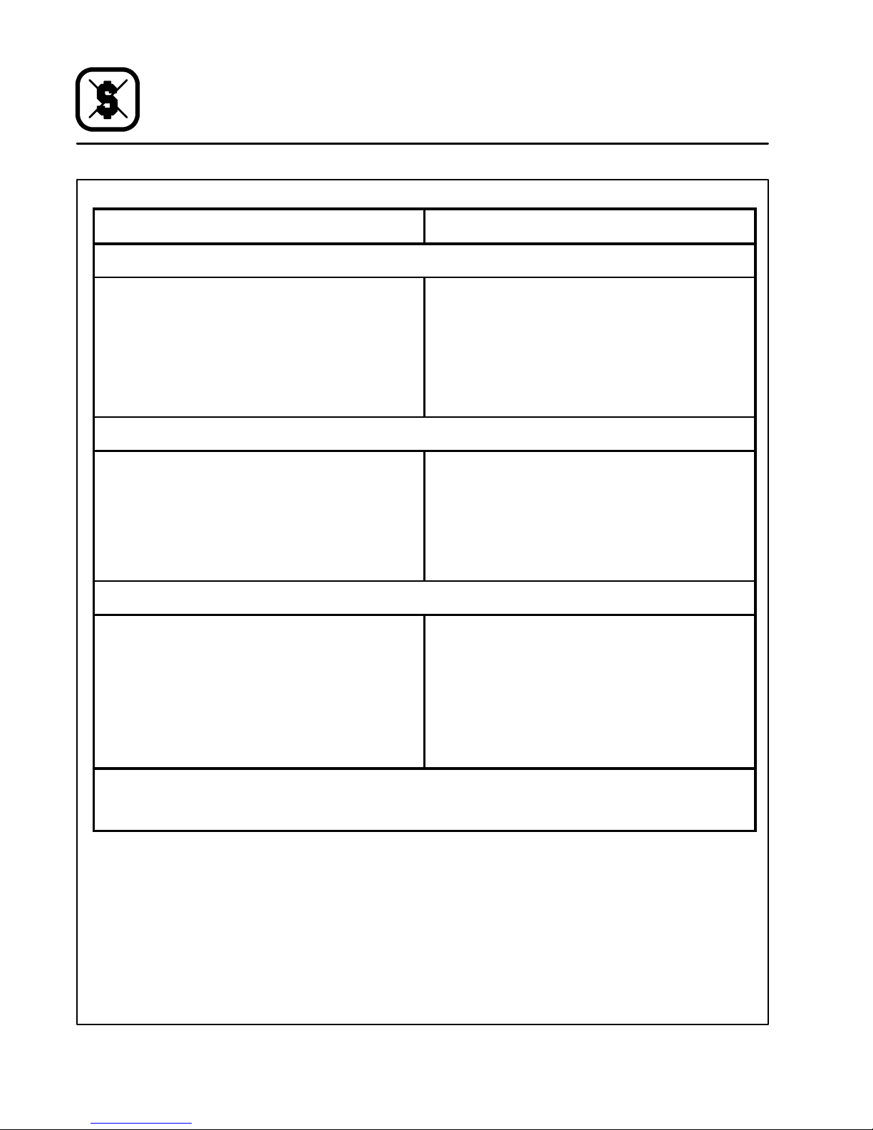
Entretien
GuidedeDétectiondesPannes
CAUSE(S) PROBABLE(S) SUGGESTION
SYMPTOME: Fonds Durs:
S
Trop de chaleur provenant de la sole
S
Pression de gaz élevée
S
Conduit d’aération défectueux (ventilation
directe trop forte)
S
Produit laissé trop longtemps dans le four
SYMPTOME: Cuissons Inégales
S
Mauvaise ventilation
S
Portesde fourlaissées ouvertes trop longtemps
S
Mauvais dosage de la pâte
S
Pression de gaz fluctuante
S
Moules déformés
S
Réduire la température et augmenter le temps
de cuisson
S
*
S
*
S
Écourter le temps de cuisson
S
*
S
Ne pas ouvrir la porte sans nécessité
S
Mesurer la pâte de manière constante
S
*
S
Changer les plats de cuisson
SYMPTOME: Produit Brûlé
S
Thermostat trop haut
S
Produit laissé dans le four trop longtemps
S
Ralenti de la flamme trop fort
S
Pression de gaz élevée
S
Thermostat mal calibré
S
Déflecteurs de chaleur abîmés
*Indiqueun type d’interventiondélicatequidevraitêtreconfiéeuniquementà un personnelqualifié.Plutôtque d’intervenirpersonnellement, en tant qu’utilisateurou acheteur de l’appareil, il est conseillé de confier TOUT réglage et/ou TOUTE réparation à un
agentcommercialou représentantlocal Blodgett.Blodgett ne saura être tenu responsabled’un dommagerésultantd’uneréparation ou d’un serviced’entretieneffectué par un personnel non qualifié.
S
Réduire la température de cuisson
S
Écourter le temps de cuisson
S
*
S
*
S
*
S
*
36
Page 41
CAUSE(S) PROBABLE(S) SUGGESTION
SYMPTOME: Produit Désséche
S
Température du four trop basse
S
Pas assez d’eau dans la préparation de la pâte
S
Thermostat mal calibré
S
Conduit d’aération défectueux (ventilation
directe trop forte)
SYMPTOME: Temps de Cuisson Prolongé
S
Mise en température trop basse
S
Pression de gaz basse
S
Ventilation trop forte
S
Ouverture des portes trop fréquente
Entretien
GuidedeDétectiondesPannes
S
Augmenter la température de cuisson
S
Augmenterla quantitéd’eau dansle mélangede
produit
S
*
S
*
S
Augmenter le temps de cuisson
S
*
S
*
S
Ne pas ouvrir la porte sans nécessité
*Indiqueun type d’interventiondélicatequidevraitêtreconfiéeuniquementà un personnelqualifié.Plutôtque d’intervenirpersonnellement, en tant qu’utilisateurou acheteur de l’appareil, il est conseillé de confier TOUT réglage et/ou TOUTE réparation à un
agentcommercialou représentantlocal Blodgett.Blodgett ne saura être tenu responsabled’un dommagerésultantd’uneréparation ou d’un serviced’entretieneffectué par un personnel non qualifié.
37
 Loading...