

Page 1

1048
GAS DECK OVEN
INSTALLATION - OPERATION - MAINTENANCE
1048
FOURS À GAZ À PLATEFORME
MANUEL D'INSTALLATION - UTILISATION - ENTRETIEN
44 Lakeside Avenue, Burlington, Vermont 05401 USA Telephone: (802) 658Ć6600 Fax: (802)864Ć0183
BLODGETT OVEN COMPANY
www.blodgett.com
PN 18648 Rev H (2/11)
E 2011 - G.S. Blodgett Corporation
Page 2

IMPORTANT
WARNING: IMPROPER INSTALLATION, ADJUSTMENT, ALTERATION, SERVICE OR
MAINTENANCE CAN CAUSE PROPERTY DAMAGE, INJURY OR DEATH. READ THE
INSTALLATION, OPERATING AND MAINTENANCE INSTRUCTIONS THOROUGHLY
BEFORE INSTALLING OR SERVICING THIS EQUIPMENT
AVERTISSEMENT: UNE INSTALLATION, UN AJUSTEMENT, UNE ALTÉRATION, UN
SERVICE OU UN ENTRETIEN NON CONFORME AUX NORMES PEUT CAUSER DES
DOMMAGES À LA PROPRIÉTE, DES BLESSURES OU LA MORT. LISEZ ATTENTIVEĆ
MENT LES DIRECTIVES D'INSTALLATION, D'OPÉRATION ET D'ENTRETIEN AVANT
DE FAIRE L'INSTALLATION OU L'ENTRETIEN DE CET ÉQUIPEMENT.
INSTRUCTIONS TO BE FOLLOWED IN THE EVENT THE USER SMELLS GAS
MUST BE POSTED IN A PROMINENT LOCATION. THIS INFORMATION MAY BE
OBTAINED BY CONTACTING YOUR LOCAL GAS SUPPLIER.
LES INSTRUCTIONS À RESPECTER AU CAS OÙ L'UTILISATEUR PERÇOIT UNE
ODEUR DE GAZ DOIVENT ÊTRE AFFICHÉES DANS UN ENDROIT BIEN VISIBLE.
VOUS POUVEZ VOUS LES PROCURER AUPRÈS DE VOTRE FOURNISSEUR DE
GAZ LOCAL.
FOR YOUR SAFETY
Do not store or use gasoline or other flammable vapors or liquids in the vicinity
of this or any other appliance.
AVERTISSEMENT
Ne pas entreposer ni utiliser de l'essence ni d'autres vapeurs ou liquides inflamĆ
mables dans le voisinage de cet appariel, ni de tout autre appareil.
The information contained in this manual is important for the proper installation,
use, and maintenance of this oven. Adherence to these procedures and instrucĆ
tions will result in satisfactory baking results and long, trouble free service.
Please read this manual carefully and retain it for future reference.
Les informations données dans le présent manuel sont importantes pour installer,
utiliser et entretenir correctement ce four. Le respect de ces instructions et procéĆ
dures permettra d'obtenir de bons résultats de cuisson et une longue durée de serĆ
vice sans problèmes. Veuillez lire le présent manuel et le conserver pour pouvoir
vous y reporter à l'avenir.
Errors: Descriptive, typographic or pictorial errors are subject to correction. SpecificaĆ
tions are subject to change without notice.
Erreurs:Les erreurs de description, de typographie ou d'illustration font l'objet de
corrections. Les caractéristiques sont sujettes à modifications sans préavis.
Page 3

THE REPUTATION YOU CAN COUNT ON
UNE RÉPUTATION SUR LAQUELLE VOUS POUVEZ COMPTER
For over a century and a half, The Blodgett Oven Company has been building
ovens and nothing but ovens. We've set the industry's quality standard for all
kinds of ovens for every foodservice operation regardless of size, application
or budget. In fact, no one offers more models, sizes, and oven applications
than Blodgett; gas and electric, fullĆsize, halfĆsize, countertop and deck, conĆ
vection, Cook'n Hold, CombiĆOvens and the industry's highest quality Pizza
Oven line. For more information on the full line of Blodgett ovens contact your
Blodgett representative.
Cela fait maintenant dessus un siècle et demi que Blodgett se spécialise dans
la fabrication de fours. Nous avons établi les normes de qualité qui s'appliĆ
quent dans l'industrie à tous les types de fours utilisés dans les services aliĆ
mentaires, quel qu'en soit la taille, l'exploitation ou le budget. En fait, ni n'offre
plus de modèles, de tailles et d'applications de fours que Blodgett. À gaz et
électriques. De tailles différentes, sur plan de travail et superposables. Qu'il
s'agisse de fours à convection, des modèles Cook'n Hold et CombiĆOven, ou
de la gamme de fours à pizzas de la plus haute qualité offerte sur le marché.
Pour de plus amples informations sur la gamme complète de fours Blodgett,
veuillez contacter votre représentant Blodgett.
Page 4

Your Service Agency's Address:
Adresse de votre agence de service:
Model/Modèl:
Serial Number/Numéro de série:
Your oven was installed by/
Installateur de votre four:
Your oven's installation was checked by/
Contrôleur de l'installation de votre four:
Page 5

Table of Contents/Table des Matières
Introduction
Oven Description and Specifications 2. . . .
Oven Components 3. . . . . . . . . . . . . . . . . . . .
Installation
Delivery and Location 4. . . . . . . . . . . . . . . . .
Oven Assembly 5. . . . . . . . . . . . . . . . . . . . . .
Packaging 5. . . . . . . . . . . . . . . . . . . . . . . . . .
Leg Attachment 5. . . . . . . . . . . . . . . . . . . . .
caster attachment 5. . . . . . . . . . . . . . . . . . .
Double Section Assembly 6. . . . . . . . . . . .
3 Piece Deflector Assembly 6. . . . . . . . . . .
Ultra Rokite Shelves 6. . . . . . . . . . . . . . . . .
Deck Seal 7. . . . . . . . . . . . . . . . . . . . . . . . . .
Flue Plates 7. . . . . . . . . . . . . . . . . . . . . . . . .
Leveling the Oven 7. . . . . . . . . . . . . . . . . . .
Adjustments Associated with Initial
Installation 7. . . . . . . . . . . . . . . . . . . . . . . . .
Ventilation 8. . . . . . . . . . . . . . . . . . . . . . . . . . .
Canopy Type Exhaust Hood 8. . . . . . . . . .
Direct Flue Arrangement 9. . . . . . . . . . . . .
Venting Problems 9. . . . . . . . . . . . . . . . . . .
Utility Connections -
Standards and Codes 10. . . . . . . . . . . . . . . . .
Gas Connection 11. . . . . . . . . . . . . . . . . . . . . .
Operation
Safety Information 14. . . . . . . . . . . . . . . . . . . .
Oven Control 15. . . . . . . . . . . . . . . . . . . . . . . . .
General Guidelines for Operating
Personnel 16. . . . . . . . . . . . . . . . . . . . . . . . . . . .
Maintenance
Cleaning and Preventative Maintenance 17.
Troubleshooting Guide 18. . . . . . . . . . . . . . . .
Introduction
Description et Spécifications du Four 20. . . .
Éléments du Four 21. . . . . . . . . . . . . . . . . . . . .
Installation
Livraison et Implantation 22. . . . . . . . . . . . . . .
Montage du Four 23. . . . . . . . . . . . . . . . . . . . .
Emballage 23. . . . . . . . . . . . . . . . . . . . . . . . .
Assemblage des Pieds 23. . . . . . . . . . . . . . .
Fixation des Roulettes 23. . . . . . . . . . . . . . .
Montage de la Section Double 24. . . . . . . .
Montage du Déflecteur en Trois
Parties 24. . . . . . . . . . . . . . . . . . . . . . . . . . . . .
Des Plaques en Rokite 24. . . . . . . . . . . . . . .
Joint de Plaque 25. . . . . . . . . . . . . . . . . . . . .
Plaques de Cheminée 25. . . . . . . . . . . . . . .
Mise à Niveau des Fours 25. . . . . . . . . . . . .
Réglages à Faire Lors de
l'Installation Initiale 25. . . . . . . . . . . . . . . . . .
Ventilation 26. . . . . . . . . . . . . . . . . . . . . . . . . . .
Hotte D'évacuation Type Voûte 26. . . . . . .
En Prise Directe 27. . . . . . . . . . . . . . . . . . . . .
Problêmes de la Ventilation 27. . . . . . . . . . .
Branchements de Service - Normes et
Codes 28. . . . . . . . . . . . . . . . . . . . . . . . . . . . . . .
Branchement de Gaz 29. . . . . . . . . . . . . . . . .
Utilisation
Information de Sécurité 32. . . . . . . . . . . . . . . .
Les Commandes du Four 33. . . . . . . . . . . . . .
Consignes Générales à l'Intention des
Utilasateurs 34. . . . . . . . . . . . . . . . . . . . . . . . . .
Entretien
Nettoyage et Entretien Préventif 35. . . . . . . .
Guide de Détection des Pannes 36. . . . . . . .
Page 6
Introduction
Oven Description and Specifications
Blodgett Deck ovens have set industry wide stanĆ
dards of excellence for baking characteristics,
performance and reliability. They remain unsurĆ
passed for product quality.
Simplicity of design and quality construction
throughout assure years of trouble free service
Natural Gas Propane Gas
US Units SI Units US Units SI Units
1048ĆB (85,000 BTU) GAS SPECIFICATIONS
Heating Value 1000 BTU/hr 37.3 MJ/m
Specific Gravity (air=1.0) 0.63 0.63 1.53 1.53
Gas Manifold Pressure 3.5" W.C. 0.87 kPa 10" W.C. 2.49 kPa
Oven Input
Per Burner
Per Oven
Main Burner Orifice Size 30 MTD* 3.3 mm 48 MTD* 1.93 mm
Pilot Burner Orifice Size .021" Dia. .53 mm .0115" Dia. .29 mm
1048ĆB (120,000 BTU) GAS SPECIFICATIONS
Heating Value 1000 BTU/hr 37.3 MJ/m
42,500 BTU/hr
85,000 BTU/Hr
when the equipment is properly installed and
maintained.
Features include a full angle iron frame, all welded
radius corners and stainless steel fronts and
doors.
3
12.4 kW
24.9 kW
3
2550 BTU/hr 95.0 MJ/m
42,500 BTU/Hr
85,000 BTU/Hr
2550 BTU/hr 95.0 MJ/m
12.4 kW
24.9 kW
3
3
Specific Gravity (air=1.0) 0.63 0.63 1.53 1.53
Gas Manifold Pressure 3.5" W.C. 0.87 kPa 10" W.C. 2.49 kPa
Oven Input
Per Burner
Per Oven
Main Burner Orifice Size 23 MTD* 3.9 mm 44 MTD* 2.18 mm
Pilot Burner Orifice Size .021" Dia. .53 mm .0115" Dia. .29 mm
NOTE: *Multiple Twist Drill
Gas Specifications are supplied in both US and SI (International Standard) units.
60,000 BTU/hr
120,000 BTU/Hr
2
17.6 kW
35.2 kW
60,000 BTU/Hr
120,000 BTU/Hr
17.6 kW
35.2 kW
Page 7
Introduction
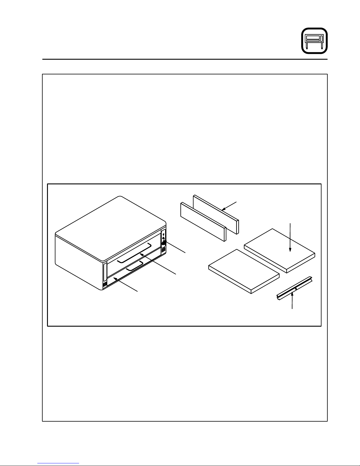
Oven Components
Ultra Rokite Deck - stone deck that absorbs heat
from below to cook the bottom of the product.
Steel Deck - absorbs heat from below to cook
the bottom of the product.
Deck Supports - hold the oven decks.
Deck Seal - seals the gap between the deck and
the front of the oven.
Control Panel - contains wiring and components
to control the oven operation.
Burner Compartment - located beneath the
cooking chamber. The burner compartment conĆ
tains the combustion burners.
Combustion Burners - provide heat to the bakĆ
ing chamber and the decks.
Deflector - diverts some of the heat from the
combustion burners to the flue plates.
Flue Plates - located on the interior side walls of
the cooking chamber. The flue plates conduct
heat from the burners to the oven cavity. The heat
cooks the top of the product before being vented
from the oven.
Flue Plates
Oven Decks
Control
Panel
Burner
Compartment
Baking
Compartment
Deck Seal
Figure 1
3
Page 8

Installation
Delivery and Location
DELIVERY AND INSPECTION
All Blodgett ovens are shipped in containers to
prevent damage. Upon delivery of your new oven:
D Inspect the shipping container for external damĆ
age. Any evidence of damage should be noted
on the delivery receipt which must be signed by
the driver.
D Uncrate the oven and check for internal damĆ
age. Carriers will accept claims for concealed
damage if notified within fifteen days of delivery
and the shipping container is retained for inĆ
spection.
The Blodgett Oven Company cannot assume
responsibility for loss or damage suffered in
transit. The carrier assumed full responsibility
for delivery in good order when the shipment
was accepted. We are, however, prepared to
assist you if filing a claim is necessary.
OVEN LOCATION
The well planned and proper placement of your
oven will result in long term operator convenience
and satisfactory performance.
The following clearances must be maintained beĆ
tween the oven and any combustible or nonĆcomĆ
bustible construction.
D Oven body right side - 6" (15 cm)
D Oven body left side - 6" (15 cm)
D Oven body back - 6" (15 cm)
D Oven body bottom - 6" (15 cm)
The following clearance must be available for serĆ
vicing.
D Oven body left side - 12" (30.5 cm)
NOTE: On gas models, routine servicing can usuĆ
ally be accomplished within the limited
movement provided by the gas hose reĆ
straint. If the oven needs to be moved furĆ
ther from the wall, the gas must first be
turned off and disconnected from the oven
before removing the restraint. Reconnect
the restraint after the oven has been reĆ
turned to its normal position.
It is essential that an adequate air supply to the
oven be maintained to provide a sufficient flow of
combustion and ventilation air.
D Place the oven in an area that is free of drafts.
D Keep the oven area free and clear of all combusĆ
tibles such as paper, cardboard, and flammable
liquids and solvents.
D Do not place the oven on a curb base or seal to
a wall. This will restrict the flow of air and prevent
proper ventilation. Pilot outages or yellow, floatĆ
ing flames on the main burners are indicative of
a lack of secondary air.
D The oven must be installed with the legs supĆ
plied by the manufacturer.
Before making any utility connections to this oven,
check the rating plate to be sure the oven specifiĆ
cations are compatible with the gas and electrical
services supplied for the oven. The rating plate is
located on the inside of the burner door.
4
Page 9

Installation
Oven Assembly
PACKAGING
Before beginning assembly and installation of the
oven, check that all necessary components have
been received. In addition to the oven itself, legs,
the proper vent, and/or other accessories may be
required.
Single Sections
1048 with Steel Deck
D Legs, regulator, set of flue plates, draft diverter
and steel deck are shipped in the oven.
D Drafthood (when supplied) is packed separately.
1048 with Ultra Rokite Decks
D Legs, regulator, set of flue plates and draft diĆ
verter are shipped in oven.
D Ultra Rokite decks are packed in a separate carĆ
ton.
D Drafthood (when supplied) is packed separately.
Double Sections
1048 with Steel Deck
D Legs and bolts, regulator, set of flue plates and
steel deck are packed in the lower section.
D Regulator, set of flue plates, draft diverter and
steel deck are packed in the upper section.
D Crown angle leg frame is packed in a separate
carton.
D Drafthood (when supplied) is packed in a sepaĆ
rate carton.
1048 with Ultra Rokite Decks
D Legs and bolts, regulator, set of flue plates are
packed in the lower section.
D Regulator, draft diverter and a set of flue plates
are packed in the upper section.
D Ultra Rokite decks are packed in two separate
cartons.
D Crown angle leg frame is packed in a separate
carton.
D Drafthood (when supplied) is packed in a sepaĆ
rate carton.
LEG ATTACHMENT
1. Put the oven onto a genie lift with the bottom
of the oven down.
2. Each leg is attached by three bolts to the unĆ
derside of the oven base frame.
CASTER ATTACHMENT
1. Bolt supports to oven with 1/2Ć13 hex head
bolts (casters with brakes should be facing
front of oven.)
2. Carefully place oven onto the casters. (It will
be necessary to have several persons lift oven
off the pallet and set it onto the casters). EnĆ
gage brakes on front casters.
NOTE: A fixed restraint must be provided if castĆ
ers are used in conjunction with a flexible
connector for movable appliances. This
restraint must secure the oven to a nonĆ
movable surface to eliminate stress on the
connector. If the oven is moved, the reĆ
straint must be reconnected after the oven
is returned to it's normal position.
5
Page 10
Installation
Oven Assembly
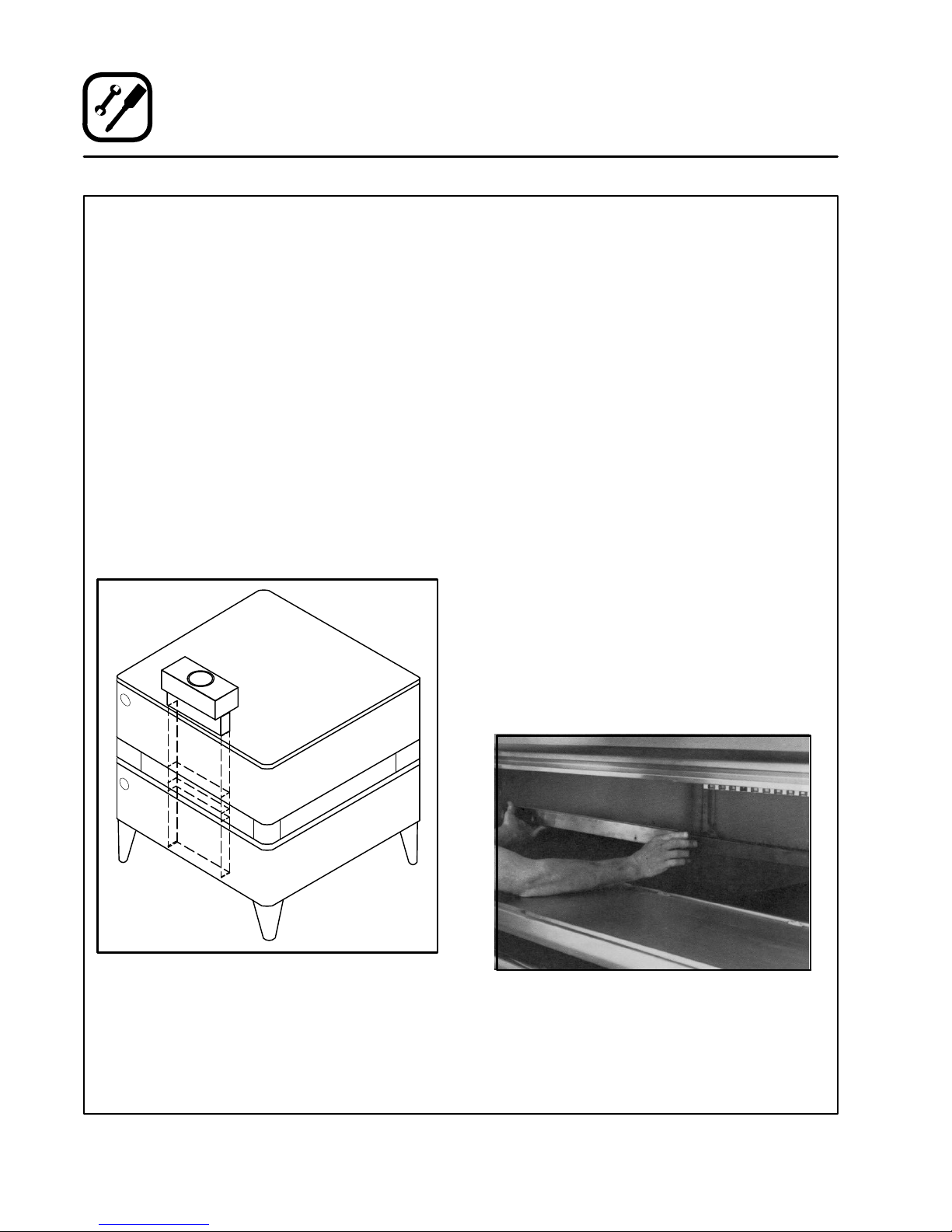
DOUBLE SECTION ASSEMBLY
1. Fasten 12" (305 mm) legs to lower section.
2. Remove the sheet metal flue cover on bottom
of UPPER SECTION FLUE ONLY and save the
two screws.
3. Fasten crown angle leg frame to upper secĆ
tions.
4. Insert double oven flue connector into upper
oven section flue until it is flush with the base
angle. Temporarily hold in place with tape.
5. Install upper section on bottom section.
6. Remove tape and slide flue connector into
position over the collar of the bottom section.
See Figure 2.
7. Fasten flue connector to bottom section with
screws from the flue cover.
8. Install drafthood or draft diverter with screws
provided.
3 PIECE DEFLECTOR ASSEMBLY
1. Deflectors are shipped in place in the oven. No
assembly is required.
2. Remove the shipping clip located in the back
center of each deflector before inserting twoĆ
piece shelf assembly.
ULTRA ROKITE SHELVES
1. Slide one half of the Ultra Rokite shelf through
the door opening. Rest the shelf on the deflecĆ
tor and slide to the rear of the oven until it
drops into the shelf support. Slide the shelf to
the right.
2. Slide the other half of the Ultra Rokite shelf on
top of first shelf to the rear until it is within the
shelf support. Slide it all the way to the left until
it drops down into place.
3. Slide both shelf halves inward so the center
joint closes.
4. Refer to preĆheating instructions supplied with
Ultra Rokite.
NOTE: Because of the weight of the Ultra Rokite
shelves, take care to avoid injury to yourĆ
self or damage to the shelves when sliding
sections into the oven. Use of 1" x 4"
pieces of lumber will help to slide shelves
into place.
Figure 2
Figure 3
6
Page 11
Installation
Oven Assembly
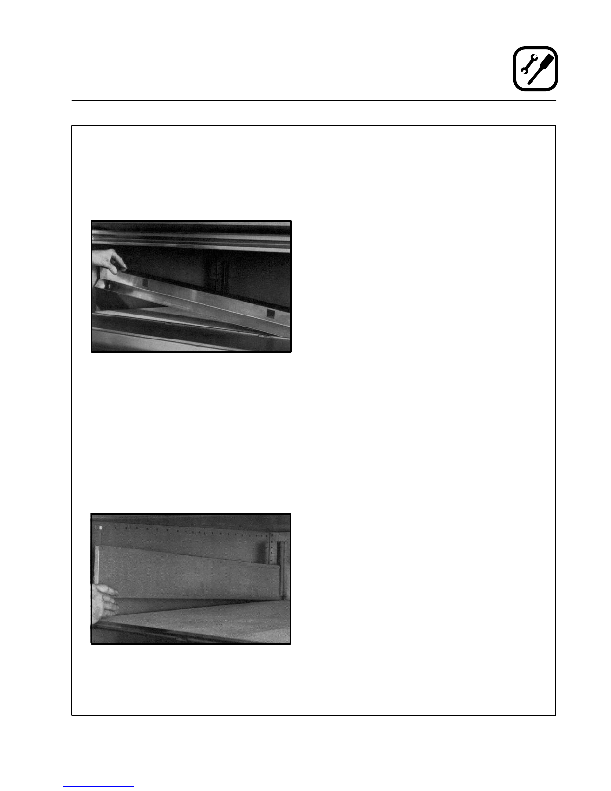
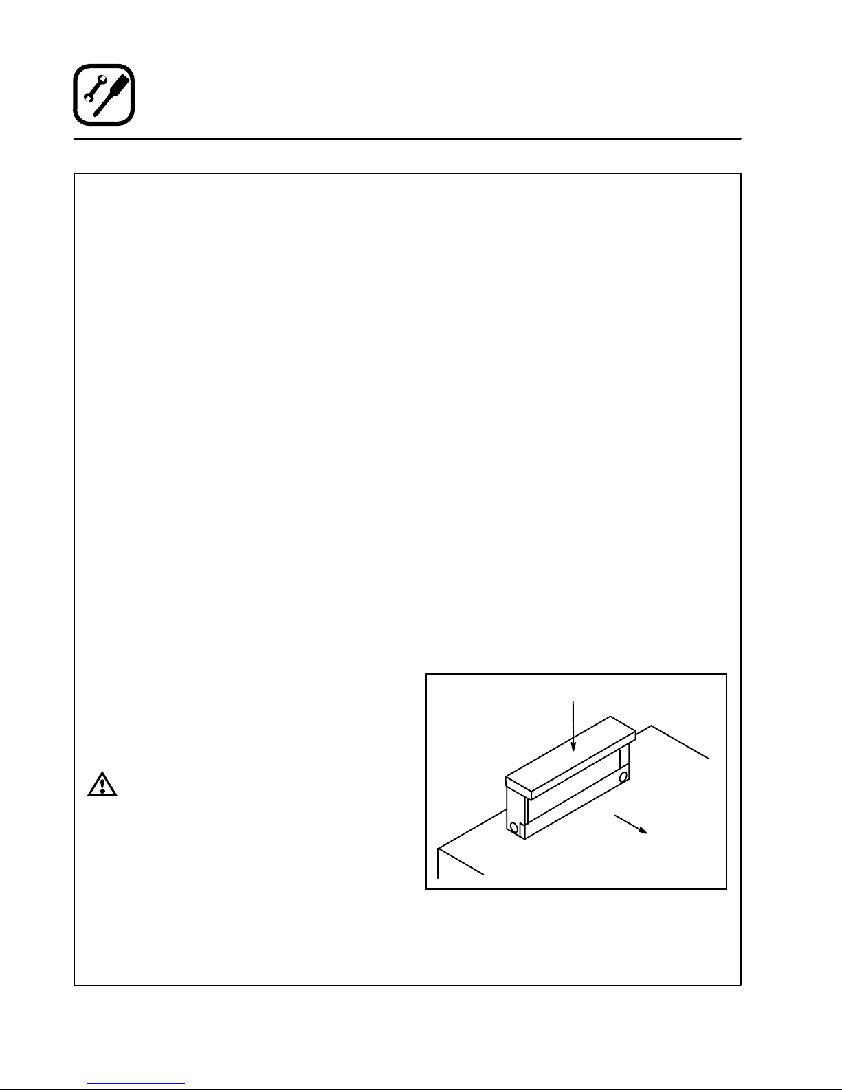
DECK SEAL
1. Place the long lip of the deck seal in front of the
shelf support angle. Place the shorter lip with
the notches between the shelf support angle
and the shelf.
2. Push seal down into place.
Figure 4
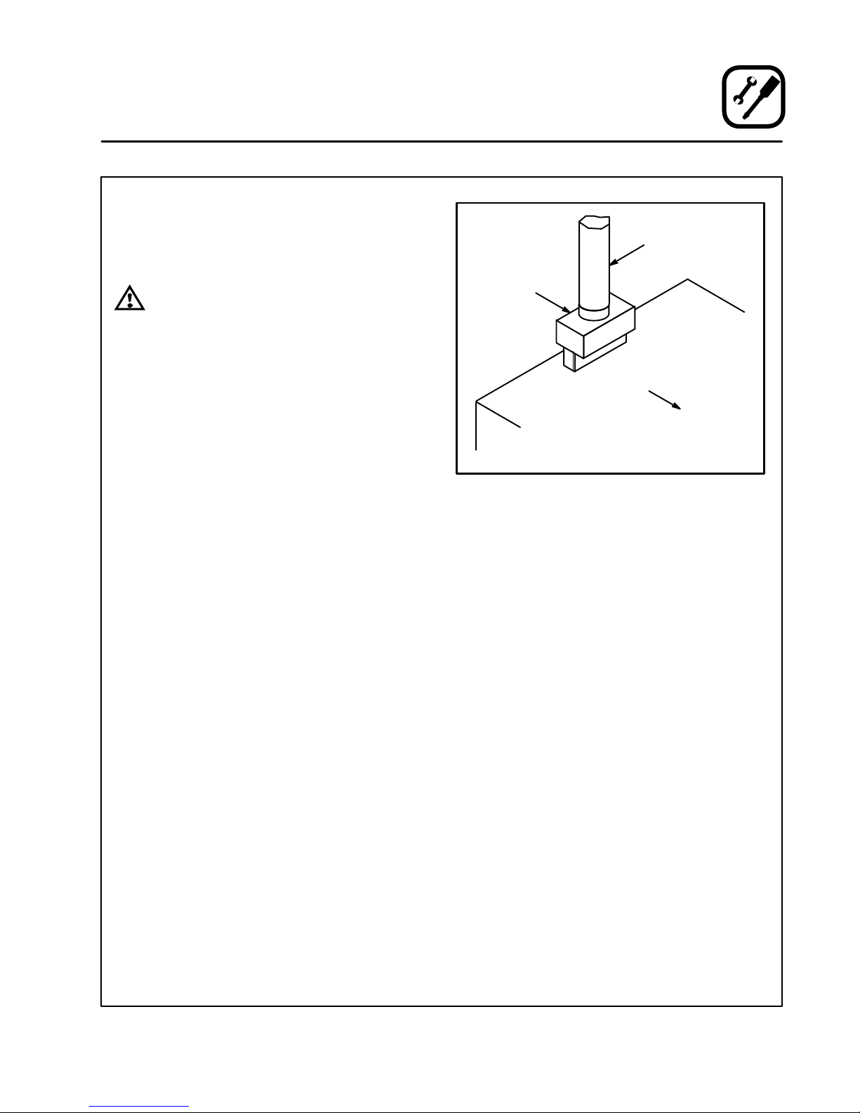
FLUE PLATES
1. Insert the back end of the flue plate in the vertiĆ
cal channel in the rear of the oven compartĆ
ment.
2. Swing the flue plate outward toward the oven
side wall.
3. Raise the front end of the flue plate about 1/2".
slip the two tabs on the flue plate in the
matched angle on the front wall.
4. Drop the flue plate down into place.
LEVELING THE OVEN
Ovens are equipped with NSF listed adjustable
sanitary legs.
1. Level ovens side to side and front to back by
placing spirit level on base frame of lower secĆ
tion.
2. Adjust leg feet in or out as appropriate.
ADJUSTMENTS ASSOCIATED WITH INITIAL
INSTALLATION
Each oven, and its component parts, have been
thoroughly tested and inspected prior to shipĆ
ment. However, it is often necessary to further test
or adjust the oven as part of a normal and proper
installation. These adjustments are the responsiĆ
bility of the installer, or dealer. Since these adjustĆ
ments are not considered defects in material or
workmanship, they are not covered by the Original
Equipment Warranty. They include, but are not
limited to:
D calibration of the thermostat
D adjustment of the doors
D burner adjustments
D leveling
D testing of gas pressure
D tightening of fasteners
No installation should be considered complete
without proper inspection, and if necessary, adĆ
justment by qualified installation or service perĆ
sonnel.
Figure 5
7
Page 12
Installation
Ventilation
Blodgett gas deck ovens are direct fired. Heat and
flue products from the burners are introduced diĆ
rectly into the baking compartment. As a result,
improper venting can have a detrimental effect on
the baking characteristics of the oven. A properly
designed ventilation system will allow the oven to
function properly, while removing unwanted vaĆ
pors and products of combustion from the operĆ
ating area.
This oven may be vented using either:
D A mechanically driven, canopy type, exhaust
hood, or
D A direct flue arrangement.
U.S. and Canadian installations
Refer to your local ventilation codes. In the abĆ
sence of local codes, refer to the National ventilaĆ
tion code titled, Standard for the Installation of
Equipment for the Removal of Smoke and Grease
Laden Vapors from Commercial Cooking EquipĆ
ment", NFPAĆ96ĆLatest Edition.
General export installations
Installation must conform with Local and National
installation standards. Local installation codes
and/or requirements may vary. If you have any
questions regarding the proper installation and/or
operation of your Blodgett oven, please contact
your local distributor. If you do not have a local disĆ
tributor, please call the Blodgett Oven Company at
0011Ć802Ć860Ć3700.
THE BLODGETT OVEN COMPANY CANNOT ASĆ
SUME RESPONSIBILITY FOR LOSS OR DAMAGE
SUFFERED AS A RESULT OF IMPROPER INSTALĆ
LATION.
CANOPY TYPE EXHAUST HOOD
A mechanically driven, canopy type exhaust hood
is the preferred method of ventilation.
The hood should be sized to completely cover the
equipment plus an overhang of at least 6" (15 cm)
on all sides not adjacent to a wall. The distance
from the floor to the lower edge of the hood should
not exceed 7' (2.1m).
The capacity of the hood should be sized approĆ
priately with provisions for an adequate supply of
make up air. Capacity is generally expressed in
ft3/min (CFM). 1 CFM of natural gas burned with
just enough air for complete combustion proĆ
duces 11 CFM of combustion products. In virtually
all appliances some excess air is used. This volĆ
ume of excess air is added to the flue products
flowing from the appliance.
NOTE: Consult your local exhaust hood contracĆ
tor for your specific installation.
Installing the canopy hood draft diverter
Ovens ordered for hood venting are supplied with
a draft diverter. Install the draft diverter as follows:
1. Place the diverter over the flue connector with
the open area facing the front of the oven. See
Figure 6.
2. Secure both ends with the sheet metal screws
provided.
Draft Diverter
WARNING:
Failure to properly vent the oven can be
hazardous to the health of the operator
and may result in operational problems,
unsatisfactory baking and possible damĆ
age to the equipment.
Damage sustained as a direct result of imĆ
proper ventilation will not be covered by
the Manufacturer's warranty.
Front of
Oven
Figure 6
8
Page 13
DIRECT FLUE ARRANGEMENT
When the installation of a mechanically driven exĆ
haust hood is impractical the oven may be vented
by a direct flue arrangement.
Installation
Ventilation
Flue
WARNING!!
It is essential that the direct flue be
installed as follows. Incorrect installation
will result in unsatisfactory baking and
oven damage.
The flue must be class B or better with a diameter
of 10" (25.4 cm). The height of the flue should rise
6Ć8 ft (2Ć2.5 m) above the roof of the building or any
proximate structure. Never direct vent the oven
into a hood. The flue should be capped with a UL
Listed type vent cap to isolate the unit from exterĆ
nal environmental conditions.
The direct vent cannot replace air consumed and
vented by the oven. Provisions must be made to
supply the room with sufficient makeĆup air. Total
makeĆup air requirements for each oven section
should be approximately 30 CFM per section. To
increase the supply air entering the room, a venĆ
tilation expert should be consulted.
Installing the draft hood
Ovens ordered for direct venting are supplied with
a draft hood. Install the draft hood as follows:
1. Place the draft hood over the flue connector.
See Figure 7.
2. Secure both ends with the sheet metal screws
provided.
Draft Hood
Front of
Oven
Figure 7
VENTING PROBLEMS
Blodgett gas deck ovens use the natural principal
of heat rising as the basic method of ventilation. If
the venting of any deck oven is either restricted or
forced in any way the baking characteristics of the
oven will be adversely affected.
Examples of forced venting include:
D installation of a fan in a direct vent pipe
D use of a canopy type hood without the draft diĆ
verter
Examples of restricted venting include:
D use of tees and elbows
D long horizontal runs
Insufficient makeĆup air can cause heated air and
combustibles to remain in the oven shortening the
life of the components.
9
Page 14
Installation
Utility Connections - Standards and Codes
THE INSTALLATION INSTRUCTIONS CONĆ
TAINED HEREIN ARE FOR THE USE OF QUALIĆ
FIED INSTALLATION AND SERVICE PERSONNEL
ONLY. INSTALLATION OR SERVICE BY OTHER
THAN QUALIFIED PERSONNEL MAY RESULT IN
DAMAGE TO THE OVEN AND/OR INJURY TO
THE OPERATOR.
Qualified installation personnel are individuals, a
firm, a corporation, or a company which either in
person or through a representative are engaged
in, and responsible for:
D the installation or replacement of gas piping
and the connection, installation, repair or servĆ
icing of equipment.
Qualified installation personnel must be experiĆ
enced in such work, familiar with all precautions
required, and have complied with all requirements
of state or local authorities having jurisdiction.
U.S. and Canadian installations
Installation must conform with local codes, or in
the absence of local codes, with the National Fuel
Gas Code, NFPA54/ANSI Z223.1-Latest Edition,
the Natural Gas Installation Code CAN/CGAĆ
B149.1 or the Propane Installation Code, CAN/
CGAĆB149.2 as applicable.
General export installations
Installation must conform with Local and National
installation standards. Local installation codes
and/or requirements may vary. If you have any
questions regarding the proper installation and/or
operation of your Blodgett oven, please contact
your local distributor. If you do not have a local disĆ
tributor, please call the Blodgett Oven Company at
0011Ć802Ć860Ć3700.
10
Page 15

Installation
L
th
pg
Gas Connection
GAS PIPING
A properly sized gas supply system is essential for
maximum oven performance. Piping should be
sized to provide a supply of gas sufficient to meet
the maximum demand of all appliances on the line
without loss of pressure at the equipment.
Example:
NOTE: BTU values in the following example are
for natural gas.
You purchase a 1048ĆBL deck oven to add to your
existing cook line.
1. Add the BTU rating of your current appliances.
Pitco Fryer 120,000 BTU
6 Burner Range 60,000 BTU
Convection Oven 50,000 BTU
Total 230,000 BTU
2. Add the BTU rating of the new oven to the toĆ
tal.
Previous Total 230,000 BTU
1048ĆB 85,000 BTU
New Total 315,000 BTU
3. Measure the distance from the gas meter to
the cook line. This is the pipe length. Let's say
the pipe length is 40' (12.2 m) and the pipe
size is 1" (2.54 cm).
4. Use the appropriate table to determine the toĆ
tal capacity of your current gas piping.
The total capacity for this example is 320,000
BTU. Since the total required gas pressure,
315,000 BTU is less than 320,000 BTU, the
current gas piping will not have to be inĆ
creased.
NOTE: The BTU capacities given in the tables are
for straight pipe lengths only. Any elbows
or other fittings will decrease pipe capaciĆ
ties. Contact your local gas supplier if you
have any questions.
Maximum Capacity of Iron Pipe in Cubic Feet
of Natural Gas Per Hour
(Pressure drop of 0.5 Inch W.C.)
Pipe
eng
(ft)
10 360 680 1400 2100 3950
20 250 465 950 1460 2750
30 200 375 770 1180 2200
40 170 320 660 990 1900
50 151 285 580 900 1680
60 138 260 530 810 1520
70 125 240 490 750 1400
80 118 220 460 690 1300
90 110 205 430 650 1220
100 103 195 400 620 1150
From the National Fuel Gas Code Part 10 Table 10Ć2
Maximum Capacity of Pipe in Thousands of
BTU/hr of Undiluted P.P. Gas at 11" W.C.
(Pressure drop of 0.5 Inch W.C.)
Pipe Length
(ft)
10 608 1146 3525
20 418 788 2423
30 336 632 1946
40 287 541 1665
50 255 480 1476
60 231 435 1337
70 215 404 1241
80 198 372 1144
90 187 351 1079
100 175 330 1014
From the National Fuel Gas Code Part 10 Table 10Ć15
Nominal Size, Inches
3/4" 1" 1Ć1/4" 1Ć1/2" 2"
Outside Diameter, Inches
3/4" 1" 1Ć1/2"
11
Page 16

Installation
Gas Connection
PRESSURE REGULATION AND TESTING
Each section of the 1048ĆB series oven is rated at
120,000 BTU per hour (35.2 kW) or 85,000 BTU
per hour (24.9 kW). At full demand, each 120,000
BTU section 1048ĆB requires 120 cubic feet per
hour (3.2 m3) Natural gas or 47 cubic feet per hour
(1.3 m3) Propane gas. Each 85,000 BTU section
1048ĆBL oven requires 85 cubic feet per hour (2.4
m3) Natural gas or 33 cubic feet per hour (0.9 m3)
Propane gas. Each oven has been adjusted at the
factory to operate with the type of gas specified on
the rating plate.
Inlet Pressure
Natural Propane
Min Max Min Max
W.C. 7.0 10.5 11.0 13.0
kPa 1.43 2.61 2.74 3.23
Manifold Pressure
Natural Propane
W.C. 3.5 10.0
kPa .87 2.49
D Inlet Pressure - the pressure of the gas before
it reaches the oven.
D Manifold Pressure - the pressure of the gas
as it enters the main burner(s).
D Min - the minimum pressure recommended to
operate the oven.
D Max - the maximum pressure at which the
manufacturer warrants the oven's operation.
Each oven is supplied with a regulator to maintain
the proper gas pressure. The regulator is essenĆ
tial to the proper operation of the oven and
must be installed. It is preset to provide the oven
with 3.5" W.C. (0.87 kPa) for natural gas and 10.5"
W.C. (2.50 kPa) for Propane at the manifold.
DO NOT INSTALL AN ADDITIONAL REGULATOR
WHERE THE OVEN CONNECTS TO THE GAS
SUPPLY UNLESS THE SUPPLY EXCEEDS THE
MAXIMUM PRESSURE.
Due to the decrease in oxygen at higher elevaĆ
tions, above 2000', the unit may need to be reĆ
rated. (The orifice size may need to be adjusted to
accomodate different air pressures at higher
elevations.) If not rerated, incomplete combustion
may occur releasing Aldehydes and CO or Carbon
Monoxide. Any of these are unacceptable and
may be hazardous to the health of the operator.
Prior to connecting the oven, gas lines should be
thoroughly purged of all metal filings, shavings,
pipe dope, and other debris. After connection, the
oven should be checked for correct gas pressure.
Installation must conform with local codes, or in
the absence of local codes, with the National Fuel
Gas Code, NFPA54/ANSI Z223.1-Latest Edition,
the Natural Gas Installation Code CAN/CGAĆ
B149.1 or the Propane Installation Code, CAN/
CGAĆB149.2 as applicable.
The oven and its individual shutoff valve must be
disconnected from the gas supply piping system
during any pressure testing of that system at test
pressures in excess of 1/2 psig (3.45kPa).
The oven must be isolated from the gas supply
piping system by closing its individual manual
shutoff valve during any pressure testing of the
gas piping system at test pressures equal or less
than 1/2 psig (3.45kPa).
12
Page 17

GAS HOSE RESTRAINT
If the oven is mounted on casters, a commercial
flexible connector with a minimum of 3/4" (1.9 cm)
inside diameter must be used along with a quick
connect device.
The restraint, supplied with the oven, must be
used to limit the movement of the unit so that no
strain is placed upon the flexible connector. With
the restraint fully stretched the connector should
be easy to install and quick connect.
The restraint (ie: heavy gauge cable) should be
1,000 lb. (453 kg) test load and should be attached
without damaging the building. DO NOT use the
gas piping or electrical conduit for the attachment
of the permanent end of the restraint! Use anchor
bolts in concrete or cement block. On wooden
walls, drive hi test wood lag screws into the studs
of the wall.
1. Mount the supplied bracket to the leg bolt just
below the gas inlet. See Figure 8.
2. The clip on restraining cable can be attached
to the mounting bracket.
Back of Oven
Restraint
Cable Bracket
Installation
Gas Connection
WARNING!!
If the restraint is disconnected for any
reason it must be reconnected when the
oven is returned to its original position.
U.S. and Canadian installations
The connector must comply with the Standard for
Connectors for Movable Gas Appliances, ANSI
Z21.69 or Connectors For Moveable Gas ApĆ
pliances CAN/CGAĆ6.16 and a quick disconnect
device that complies with the Standard for QuickĆ
Disconnect Devices for Use With Gas Fuel, ANSI
Z21.41 or Quick Disconnect For Use With Gas Fuel
CAN 1Ć6.9. Adequate means must be provided to
limit the movement of the appliance without deĆ
pending on the connection and the quick disconĆ
nect device or its associated piping. Adequate
means must be provided to limit the movement of
the appliance without depending on the connecĆ
tion and the quick disconnect device or its associĆ
ated piping.
General export installations
The restraint and quick connect must conform
with Local and National installation standards. LoĆ
cal installation codes and/or requirements may
vary. If you have any questions regarding the propĆ
er installation and/or operation of your Blodgett
oven, please contact your local distributor. If you
do not have a local distributor, please call the
Blodgett Oven Company at 0011Ć802Ć860Ć3700.
Double stacked unit shown. Use the same procedure for
single units with 25" (64 cm) legs.
Figure 8
13
Page 18
Operation
Safety Information
THE INFORMATION CONTAINED IN THIS SECĆ
TION IS PROVIDED FOR THE USE OF QUALIFIED
OPERATING PERSONNEL. QUALIFIED OPERATĆ
ING PERSONNEL ARE THOSE WHO HAVE
CAREFULLY READ THE INFORMATION CONĆ
TAINED IN THIS MANUAL, ARE FAMILIAR WITH
THE FUNCTIONS OF THE OVEN AND/OR HAVE
HAD PREVIOUS EXPERIENCE WITH THE OPĆ
ERATION OF THE EQUIPMENT DESCRIBED. ADĆ
HERENCE TO THE PROCEDURES RECOMĆ
MENDED HEREIN WILL ASSURE THE
ACHIEVEMENT OF OPTIMUM PERFORMANCE
AND LONG, TROUBLEĆFREE SERVICE.
SAFETY TIPS
For your safety read before operating
What to do if you smell gas:
D DO NOT try to light any appliance.
D DO NOT touch any electrical switches.
D Use an exterior phone to call your gas supplier
immediately.
D If you cannot reach your gas supplier, call the
fire department.
What to do in the event of a power failure:
D Turn all switches to off.
NOTE: In the event of a shutĆdown of any kind, alĆ
low a five (5) minute shut off period before
attempting to restart the oven.
General safety tips:
D DO NOT use tools to turn off the gas control. If
the gas cannot be turned off manually do not try
to repair it. Call a qualified service technician.
D If the oven needs to be moved for any reason,
the gas must be turned off and disconnected
from the unit before removing the restraint
cable. Reconnect the restraint after the oven
has been returned to its original location.
D DO NOT remove the control cover unless the
oven is unplugged.
Please take the time to read the following operatĆ
ing instructions. They are the key to the successful
operation of your Blodgett deck oven.
14
Page 19

Operation
Oven Control
OPERATION
The operation of the 1048 Series Oven is as simple
as 1, 2, 3. - Lighting, Preheating and Loading.
Lighting
1. Turn the MANUAL CONTROL VALVE (2) to OFF.
2. Push the red button on the AUTOMATIC
1
2
3
SAFETY PILOT VALVE (1).
3. Apply a lighted match or taper to pilot burner.
4. After pilot burner lights, continue to depress
red button for about 30 seconds and release.
5. Turn the MANUAL CONTROL VALVE (2) to ON.
6. Set THERMOSTAT (3) to desired temperature.
Preheating
1. On initial startup, preheat the oven to 600_F
(315_C) over a period of four hours in increĆ
ments of 100_F (55_C) starting at 300_F
(149_C). Check the oven periodically. This will
temper the Ultra Rokite shelves and burn off
any oil and fiberglass residue.
NOTE: The 1048 (with Ultra Rokite shelves)
will require an additional 20 minutes
on a preheat to 600_F (315_C).
Loading
CONTROL DESCRIPTION
1. AUTOMATIC SAFETY PILOT VALVE - proĆ
vides complete gas shutĆoff in the event of piĆ
lot failure.
2. MANUAL CONTROL VALVE - provides manĆ
ual control of gas flow to the main burner
through the thermostat.
3. THERMOSTAT - Provides regulation of oven
temperature at setting selected by the oven
operator.
Pizza in pans should be placed in rotation on the
shelf allowing it to recover its loss of temperature
from the previous bake. Do not allow pans to touch
each other or sides of oven. Open doors as selĆ
dom as possible.
The deck is intended for cooking pizza and bread
products, other types of food may be cooked in
pans or containers.
To turn the oven off
1. Turn the MANUAL CONTROL VALVE (1) to OFF.
NOTE: When the oven is shut down, place the
Main Manual Control Valve in the OFF
position. It is not necessary to extinguish
the pilot flame.
15
Page 20

Operation
General Guidelines for Operating Personnel
COOK TIMES AND TEMPERATURES
Cook Temperatures
Cook temperatures vary with different products.
Experiment with the initial bakes until you find the
ideal combination of time and temperature.
Example: pizza
1. Run several bakes at 500_F (260_C). Make
note of the time required to achieve a firm
crust.
2. If the cheese breaks down too quickly or
scorches, lower the temperature and lengthĆ
en the bake time.
3. If faster production is desired, run additional
bakes increasing the temperature by increĆ
ments of 25_F (15_C).
4. Record the results to determine the highest
temperature at which you can bake and
achieve quality results with maximum producĆ
tion.
NOTE: Pull time is critical at high temperatures.
Cook Time
Cook times vary with the amount of product
loaded, the type of pan and the temperature. RaisĆ
ing the temperature to lower the cook time is effecĆ
tive to a point. Then the quality of the bake begins
to suffer.
BAKING TIPS
D Scale dough for consistent product.
D Proof dough to proper consistency.
D Refrigerated dough or pies should be brought
to room temperature before baking. Bubbles
may occur when baking refrigerated product.
Break bubbles if necessary.
D Alternate use between upper and lower section
in a double oven.
D Avoid frequent needless opening of the door
D Rotate product placement in the oven.
16
Page 21

Maintenance
Cleaning and Preventative Maintenance
CLEANING THE OVEN
Painted and stainless steel ovens may be kept
clean and in good condition with a light oil.
1. Saturate a cloth, and wipe the oven when it is
cold.
2. Dry the oven with a clean cloth.
On the stainless front or interiors, deposits of
baked on splatter may be removed with any nonĆ
toxic industrial stainless steel cleaner. Heat tint
and heavy discoloration may be removed with any
nonĆtoxic commercial oven cleaner.
1. Apply cleaners when the oven is cold, and alĆ
ways rub with the grain of the metal.
Clean Ultra Rokite decks with a triangular scraper
used for cleaning broiler grids. IMPORTANT -
DO NOT use water or any other liquids to clean
the deck!
Clean the aluminized interior portion of the oven
with a mild detergent. DO NOT use caustic soluĆ
tions such as ammonia, lye or soda ash. DO NOT
use domestic oven cleaners. Any of these prodĆ
ucts will damage the aluminum coating.
Daily Cleaning
D Remove residue from beneath the doors with a
small broom or brush.
Weekly Cleaning
D Brush out the combustion compartment and
control area.
6 Month Cleaning
D Clean secondary air ducts and air entry ports.
NOTE: If the oven is moved the restraint must be
reconnected after the unit is returned to it's
regular position.
PREVENTATIVE MAINTENANCE
The best preventative maintenance measures are,
the proper installation of the equipment and a proĆ
gram for routinely cleaning the ovens.
This oven requires no lubrication, however, the
venting system should be checked annually for
possible deterioration resulting from moisture and
corrosive flue products.
If maintenance or repairs are required, contact the
factory, the factory representative or a local
Blodgett service company.
17
Page 22

Maintenance
Troubleshooting Guide
POSSIBLE CAUSE(S) SUGGESTED REMEDY
SYMPTOM: Strong bottoms on the bakes
S Too much bottom heat
S High gas pressure
S Faulty flue (strong direct vent)
S Product left in the oven too long
SYMPTOM: Uneven bakes
S Poor ventilation
S Oven doors left open too long
S Improper scaling of dough
S Fluctuating gas pressure
S Warped pans
SYMPTOM: Product burning
S Thermostat set too high
S Product left in the oven too long
S ByĆpass flame too high
S High gas pressure
S Thermostat out of calibration
S Heat deflectors worn out
S Reduce cook temperature and increase time
S *
S *
S Shorten cook time
S *
S Do not open door unnecessarily
S Scale dough consistently
S *
S Change pans
S Reduce cook temperature
S Shorten cook time
S *
S *
S *
S *
*Denotes remedy is a difficult operation and should be performed by qualified personnel only. It is recommended, however, that
All repairs and/or adjustments be done by your local Blodgett service agency and not by the owner/operator. Blodgett cannot asĆ
sume responsibility for damage as a result of servicing done by unqualified personnel.
18
Page 23

POSSIBLE CAUSE(S) SUGGESTED REMEDY
SYMPTOM: Product dried out
Maintenance
Troubleshooting Guide
S Oven temperature too low
S Not using enough water in the mix
S Thermostat out of calibration
S Faulty flue (strong direct vent)
SYMPTOM: Extended baking times
S Temperature setting too low
S Low gas pressure
S Strong ventilation
S Excessive door openings
*Denotes remedy is a difficult operation and should be performed by qualified personnel only. It is recommended, however, that
All repairs and/or adjustments be done by your local Blodgett service agency and not by the owner/operator. Blodgett cannot asĆ
sume responsibility for damage as a result of servicing done by unqualified personnel.
S Increase cook temperature
S Increase water in product mix
S *
S *
S Increase cook time
S *
S *
S Do not open door unnecessarily
19
Page 24

Introduction
Description et Spécifications du Four
Les fours à plateforme Blodgett ont établi les hauts
standards de qualité de l'industrie par leurs caracĆ
téristiques de cuisson au four, le rendement et la
fiabilité. Ils restent sans égal pour la qualité du proĆ
duit.
La simplicité de conception et la qualité de leur
construction jusque dans les moindres détails asĆ
Gaz Naturel Gaz Propane
Unités US Unités SI Unités US Unités SI
1048ĆB (85,000 BTU) SPECIFICATIONS POUR GAZ
Valeur de Chauffe 1000 BTU/hr 37.3 MJ/m
Gravité Specifique (air=1.0) 0.63 0.63 1.53 1.53
Pression arrivée de gaz au
collecteur
Consommation Four
Par brûleur
Par four
Brûleur principal taille orifice 30 MTD* 3.3 mm 48 MTD* 1.93 mm
3.5" W.C. 0.87 kPa 10" W.C. 2.49 kPa
42,500 BTU/hr
85,000 BTU/Hr
surent des années de service sans problème
quand l'équipement est correctement installé et
entretenu.
Les caractéristiques comprennent un bâti entièreĆ
ment en fer en L, des rayons d'angles entièrement
soudés et, un avant et des portes en acier inoxydĆ
able.
3
12.4 kW
24.9 kW
2550 BTU/hr 95.0 MJ/m
42,500 BTU/Hr
85,000 BTU/Hr
12.4 kW
24.9 kW
3
Brûleur veilleuse taille orifice .021" Dia. .53 mm .0115" Dia. .29 mm
1048ĆB (120,000 BTU) SPECIFICATIONS POUR GAZ
Valeur de Chauffe 1000 BTU/hr 37.3 MJ/m
Gravité Specifique (air=1.0) 0.63 0.63 1.53 1.53
Pression arrivée de gaz au
collecteur
Consommation Four
Par brûleur
Par four
Brûleur principal taille orifice 23 MTD* 3.9 mm 44 MTD* 2.18 mm
Brûleur veilleuse taille orifice .021" Dia. .53 mm .0115" Dia. .29 mm
REMARQUE:*Mèche hélicoïdale multiple
Specifications fournies en unités US et SI
3.5" W.C. 0.87 kPa 10" W.C. 2.49 kPa
60,000 BTU/hr
120,000 BTU/Hr
17.6 kW
35.2 kW
3
2550 BTU/hr 95.0 MJ/m
60,000 BTU/Hr
120,000 BTU/Hr
17.6 kW
35.2 kW
3
20
Page 25

Introduction
Éléments du Four
Plateforme de Rokite - plateforme de pierre qui
absorbe la chaleur du bas du four pour cuire le
dessous du produit.
Plateforme d'acier - qui absorbe la chaleur du
bas du four pour cuire le dessous du produit.
Supports de plateforme - supportent les plateĆ
formes du four.
Joint d'étanchéité de la plateforme - bouche
l'espace entre la plateforme et l'avant du four.
Panneau de Contrôle - contient les câblages et
les éléments permettant de contrôler le fonctionĆ
nement du four.
Compartiment des brûleurs - situé au-desĆ
sous de la chambre de cuisson. Ce compartiment
contient les brûleurs à combustion directe.
Brûleurs à combustion directe - fournissent la
chaleur à la chambre de cuisson et aux plateĆ
formes.
Déflecteur - détourne une partie de la chaleur
des brûleurs à combustion directe vers les
plaques tubulaires.
Plaques tubulaires - situées sur les parois intéĆ
rieures de la chambre de cuisson. Les plaques tuĆ
bulaires conduisent la chaleur des brûleurs à la
cavité du four. La chaleur cuit le dessus du produit
avant d'être évacuée du four.
Plaques tubulaires
Plateforme
Panneau de
Contrôle
Compartiment
des brûleurs
Compartiment
de cuisson
Joint d'étanchéité
de la plateforme
Figure 9
21
Page 26

Installation
Livraison et Implantation
LIVRAISON ET INSPECTION
Tous les fours sont expédiés en conteneurs. A la
réception de votre four Blodgett vous devez:
D Vérifier que les emballages ne sont pas abimés.
Toute défection dans l'emballage doit être noĆ
tée sur l'accusé de reception de la marchanĆ
dise; celuiĆci doit être signé par le chauffeur.
D Sortir le four de son emballage et vérifier son
bon état. Les transporteurs n'acceptent les réĆ
clamations et plaintes que si elles sont faites
dans les quinze jours qui suivent la livraison et
si l'emballage a été conservé afin d'être inspecĆ
té.
La Blodgett Oven Co., n'est pas responsable
des dégâts subis pendant le transport. Le
transporteur est seul responsable de la livraiĆ
son du matériel en bon état lorsque l'expédiĆ
tion a été acceptée. Néanmoins, nous sommes
à votre disposition pour vous aider à composer
votre dossier de réclamation.
IMPLANTATION DU FOUR
L'implantation correcte et bien étudiée du four
sera à l'avantage à long terme de l'opérateur et
permettra d'obtenir un rendement satisfaisant.
Les espaces de dégagement ci-dessous doivent
être prévus entre le four et toute construction comĆ
bustible ou non.
D Côté droit du four - 15 cm
D Côté gauche du four - 15 cm
D Arrière du four - 15 cm
D Dessous du four - 15 cm
Les espaces de dégagement ciĆdessous doivent
être possible pour permettre l'entretien.
D Côté gauche du four - 30.5 cm
REMARQUE:L'entretien régulier peut en général
être effectué dans les limites du déĆ
placement que permet la chaîne de
retenue. Si le four doit être plus écarĆ
té du mur, l'alimentation en gaz doit
être coupée et la canalisation déĆ
branchée du four avant d'enlever la
chaîne. CelleĆci doit être utilisée pour
empêcher d'exercer toute contrainte
sur le coupleur de gaz.
Il est essentiel qu'une circulation d'air adéquate
au four soit maintenue pour apporter un débit d'air
de combustion et de ventilation suffisant.
D L'emplacement ne doit pas avoir de courants
d'air.
D Maintenez la zone du four libre et dégagée de
tous matériaux combustibles tels que le papier,
le carton, ainsi que les liquides et solvants inĆ
flammables.
D Le four ne doit pas être placé sur une surface inĆ
curvée ou fixé au mur. L'empêcherait l'air de cirĆ
culer librement vers le compartiment de comĆ
bustion et par conséquent produirait une
mauvaise ventilation. L'extinction de la veilleuse
ou des flammes jaunes provenant du brûleur
principal indiquent un manque d'arrivée d'air
secondaire.
D Le four doit être installé sur les pieds fournis par
le fabricant.
Veuillez vérifier le tableau de spécifications avant
d'effectuer tout branchement sur ce four afin de
vous assurer ques les spécifications de ce four
sont compatibles avec le gaz d'arrivée au four. Le
tableau de spécifications se trouve à l'intérieur de
la porte du compartiment brûleur. Il faut ouvrir la
porte pour le trouver.
22
Page 27

Installation
Montage du Four
EMBALLAGE
Avant de commencer le montage du four il faut véĆ
rifier que tous ses composants sont présents. En
plus du four, luiĆméme, il faut des pieds, un
système de ventilation et/ou d'autres accessoires.
Pour les sections simples:
1048 avec des plaques en metallique
D Des pieds, une régulateur, un collet de tuyau,
un diverteur d'air et des plaques en metallique
sont emballés dans le four.
D Une hotte à air (quand elle est fournie) est emĆ
ballés dans une boîte individuelle.
1048 avec des plaques en Rokite
D Des pieds, une régulateur, un collet de tuyau, et
un diverteur d'air sont emballés dans le four.
D Des plaques en Rokite sont emballés dans une
boîte individuelle.
D Une hotte à air (quand elle est fournie) est emĆ
ballés dans une boîte individuelle.
Pour les sections doubles:
1048 avec des plaques en metallique
D Des pieds et boulons, une régulateur, un collet
de tuyau, un raccordement de tuyau pour four
double et des plaques en metallique sont emĆ
ballés dans la section du bas.
D Une régulateur, un collet de tuyau et des
plaques, un diverteur d'air, en metallique sont
emballés dans la section du haut.
D Le cadre de pied d'angle est emballés dans une
boîte individuelle.
D Une hotte à air (quand elle est fournie) est emĆ
ballés dans une boîte individuelle.
Double 1048 avec des plaques en Rokite
D Des pieds et boulons et un raccordement de
tuyau pour four double sont emballés dans la
section du bas.
D Une régulateur, un diverteur d'air, et un collet de
tuyau sont emballés dans la section du haut.
D Les plaques en Rokite sont emballées dans
deux boites en carton séparées.
D Le cadre de pied d'angle est emballés dans une
boîte individuelle.
D Une hotte à air (quand elle est fournie) est emĆ
ballés dans une boîte individuelle.
ASSEMBLAGE DES PIEDS
2. Pousser le four, couché sur le dos, sur un éléĆ
vateur.
3. Chaque pied est fixé par trois boulons sous la
base du four.
FIXATION DES ROULETTES
1. Boulonnez les supports à celuiĆci au moyen
de boulons de 1/2Ć13 à tête hex (les roulettes
freinées doivent être tournées vers le devant
du four).
2. Faites reposer avec précaution le four sur les
roulettes. (Il sera nécessaire de le faire soulevĆ
er de la palette et de le faire reposer sur les
roulettes par plusieurs personnes.) Serrez les
freins des roulettes avant.
REMARQUE:Un dispositif de retenue fixe doit être
fourni si des roulettes sont utilisés
avec un connecteur flexible pour des
appareils portatifs. Ce dispositif doit
fixer le four à une surface immobile
pour éliminer toute contrainte pouĆ
vant être subie par le connecteur. Si
le four est déplacé, il faut rebrancher
le connecteur après avoir remis le
four en position normale.
23
Page 28

Installation
Montage du Four
MONTAGE DE LA SECTION DOUBLE
1. Fixer les pieds de 12" (305 mm) à la section du
bas.
2. Retirer la gaine de métal qui recouvre le tuyau
au bas de la SECTION SUPERIEURE DU TUYĆ
AU SEULEMENT et conserver les deux vis.
3. Attacher le cadre de pied d'angle de ragrandir
aux sections supérieures.
4. Insère le four double connection de tuyau en
la section supérieure de four tuyau jusqu'à lui
est nettoyage avec l'angle de base. Tient temĆ
porairement dans l'endroit avec la bande.
5. Installer la section du haut sur la section du
bas.
6. Enlever la bande et diapositive la connection
de tuyau en la position sur le col de la section
du bas. Voir Figure 10.
7. Attacher la connection du tuyau au section du
bas avec des vis du tuyau couverture.
8. Monter la hotte à air ou le diverteur d'air avec
les vis fournies.
MONTAGE DU DÉFLECTEUR EN TROIS
PARTIES
1. Les déflecteurs sont expédiés en place dans
le four. Leur montage n'est pas nécessaire.
2. Retirer la patte d'attachement qui se trouve au
centre arrière de chaque déflecteur avant d'inĆ
sérer l'ensemble fait de deuxĆparties de la
plaque.
DES PLAQUES EN ROKITE
1. Saisir la plaque en Rokite dans l'ouverture de
la porte. La glisser par l'ouverture de la porte
vers l'arrière du four jusqu'à ce qu'elle repose
la plaque sur le support de plaque. La glisser
vers la droit jusqu'à ce qu'elle tombe en place.
2. Glisser l'une des deux plaques étroites par
l'ouverture de la porete vers l'arrière de l'autre
plaque jusqu'à ce qu'elle soit dans le support
de plaque. La glisser vers la gauche jusqu'à
ce qu'elle tombe en place.
3. Presser les deux parties de plaques vers l'intéĆ
rieur de telle sorte que lesjoints se ferment.
4. Référer à preĆchauffage instructions approviĆ
sionnèes avec Rokite.
REMARQUE:A cause du poids des plaques en RoĆ
kite, faites attention de ne pas vous
blesser ou d'abîmer les plaques lorsĆ
que vous les faites glisser dans le
four.
Figure 10
Figure 11
24
Page 29

Installation
Montage du Four
JOINT DE PLAQUE
1. Placer la partie longue de la lèvre du joint deĆ
vant l'angle de support du plateau. Placer la
partie courte de la lèvre qui a des encoches
entre l'angle du support de plaque et la
plaque.
2. Pousser vers le bas dand son emplacement.
Figure 12
PLAQUES DE CHEMINÉE
1. Insérer l'arrière de la plaque de cheminée
dans la glissière verticale située à l'arrière du
compartiment du cuisson.
2. Pousser la plaque vers l'extérieur en direction
de la paroi latèrale du four.
3. Soulever l'extrémité avant de la plaque de 1/2
pouce afin de permettre aux deux pattes siĆ
tuées sur les plaque de s'aligner et de s'enĆ
gager dans les glissières situées sur la paroi
avant du four.
4. Laisser retomber la plaque dans son emĆ
placement.
MISE À NIVEAU DES FOURS
Les fours sont équipés de pieds ajustables suivant
le code NSF.
1. Mettre les fours à niveau latéralement et vertiĆ
calement en plaçant le niveau sur la surface
de la section inférieure.
2. Faire les réglages suivant le besoin.
RÉGLAGES À FAIRE LORS DE
L'INSTALLATION INITIALE
Chaque four ainsi que ses composants ont été
soigneusement testés et inspectés avant d'être
expédiés. Cependant, il est bien souvent nécessĆ
aire de faire des vérifications et des réglages sur
place au moment de l'installation initiale. Ceci est
un procédé normal. De tels réglages sont sous la
responsabilité du vendeur ou de l'installateur et ne
sont pas imputables à des défauts de fabrication
ou de matériau. Par conséquent, ces réglages ne
sont pas couverts par la garantie de l'équipment
d'origine. Ces réglages comprennent, sans s'y
limiter:
D le calibrage du thermostat
D le réglage des portes
D réglage du brûleur
D la mise de niveau
D la vérification de la pression du gaz
D le serrage des boulons
On ne peut considérer une installation achevée
tant qu'un personnel qualifié n'a pas procédé à sa
vérification complète et fait les réglages nécessairĆ
es s'il en est besoin.
Figure 13
25
Page 30

Installation
Ventilation
Un système de ventilation planifié et installé est
absolument nécessaire car il permet un bon foncĆ
tionnement du four tout en débarassant la surface
de travail des buées et résidus de combustion.
Il y a deux méthodes de ventilation acceptables
pour le four:
D Soit une hotte d'évacuation, de type voûte méĆ
canique.
D Soit une installation à prise directe.
Installation aux États-Unis et au Canada
Se reporter aux codes locaux de la ventilation. En
l'absence de codes locaux, se reporter au code
national de la ventilation intitulé "Normes pour
l'installation d'équipements pour l'enlèvement
des fumées et vapeurs grasses provenant d'éĆ
quipements commerciaux pour la cuisine",
NFPA-96- Édition la plus récente.
AVERTISSEMENT:
Un mauvais système d'aération peut
aboutir à un mauvais fonctionnement du
four, des résultats de cuisson peu satisĆ
faisants; il peut également abîmer l'appaĆ
reil.
Les dégâts causés par une mauvaise venĆ
tilation ne sont pas couverts par la garanĆ
tie du fabricant.
HOTTE D'ÉVACUATION TYPE VOÛTE
La méthode de ventilation la meilleure est celle qui
utilise une hotte de ventilation adéquate à mécaniĆ
que.
La hotte doit être conçue pour couvrir la totalité de
l'appareil à ventiler avec en plus un surplomb se
15 cm (6") de chaque côté de l'appareil non adjaĆ
cent au mur. La distance du plancher à l'extremité
la plus basse de la hotte ne doit pas dépasser sept
2.1m (7').
Le volume total d'air neuf et d'évacuation à consiĆ
dérer lors de la détermination de la capacité de
hotte nécessaire est d'environ 11 CFM pour chaĆ
que section de four.
Installation du déviateur de tirage
Les fours commandés pour hotte d'évacuation
sont fournis avec un déviateur de tirage. Installer
le déviateur de tirage comme suit :
1. Placer le déviateur auĆdessus du connecteur
de cheminée avec la partie ouverte tournée
vers l'avant du four. Voir Figure 14.
2. L'assujettir des deux côtés avec les vis à tôle
fournies.
Divertisseur d'air
Avant du
four
Figure 14
26
Page 31

EN PRISE DIRECTE
Quand l'installation d'une hotte aspirante mécaniĆ
que est impossible ou peu pratique à réaliser, on
peut ventiler le four au moyen d'une installation en
prise directe.
AVERTISSEMENT!!
Quand on utilise un système à prise diĆ
recte il faut absolument suivre le schéma.
Une installation de ventilation à prise diĆ
recte qui est défectueuse donnera des réĆ
sultats de cuisson peu satisfaisants et
causera des dégâts prématurés aux éléĆ
ments brûleurs.
La cheminée doit être de classe B ou mieux avec
un diamètre de 25.4 cm (10"). La hauteur de la
cheminée doit dépasser de 2 à 2,5 m (6-8') le
haut du toit du bâtiment ou autre structure proche.
Ne jamais diriger la ventilation du four dans une
hotte. La cheminée doit être chapeautée avec une
coiffe de type homologué UL, pour isoler la chemiĆ
née des intempéries extérieurs.
Dans ce cas îl est important de fournir assez d'air
secondaire car l'installation à pris directe ne peut
pas renouveler l'air absorbé et ventilé par le four.
Le volume total d'air neuf et d'évacuation à consiĆ
dérer lors de la détermination de la capacité de
hotte nécessaire est d'environ 30 CFM pour chaĆ
que section de four. Pour augmenter la circulation
d'air dans la pièce, un expert en ventilation doit
être consulté.
Installation de la hotte de tirage
Les four commandés pour la ventilation directe
sont fournis avec une hotte de tirage. Installer la
hotte de tirage comme suit :
1. Placer la hotte de tirage au-dessus du conĆ
necteur de cheminée. Voir Figure 15.
2. L'assujettir des deux côtés avec les vis à tôle
fournies.
Installation
Ventilation
Cheminée
Hotte de
tirage
Avant du
four
Figure 15
PROBLÊMES DE LA VENTILATION
La Série 1048 utilise le principe naturel de la chaĆ
leur montante comme base de sa ventilation. Si
par n'importe quel moyen l'on restreint ou l'on
force la ventilation des fours del la Série 1048, les
caractéristiques de cuisson du four seront défaĆ
vorablement affectées.
Par exemple: ventilation forcée
D l'utilisation d'un ventilateur dans le tuyau à prise
directe
D l'installation sur le four d'une hotte d'aération
qui n'est pas installée avec le diverteur d'air en
forme de L
Par exemple: ventilation restreinte
D des tés et coudes
D des sections horizontales
Un air d'appoint insuffisant peut être cause que
l'air chaud et les combustibles restent dans le four,
réduisant la durée utile des composants.
27
Page 32
Installation
Branchements de Service - Normes et Codes
LES CONSEILS D'INSTALLATION ET D'ENTREĆ
TIEN CONTENUS DANS CE MANUEL NE
S'ADRESSENT QU'Á UN PERSONNEL QUALIĆ
FIÉ. UN PERSONNEL NON QUALIFIE PEUT SE
BLES SER ET/OU ABÎMER LE FOUR LORS DE
SON INSTALLATION ET/OU SON ENTRETIEN.
Un personnel d'installation qualifié est représenté
soit par des personnes physiques, soit par un soĆ
ciété, une usine, une corporation qui en personne
ou par l'intermédiaire d'un représentant s'engage
à et est responsable de:
D l'installation ou le remplacement de conduits de
gaz, ou le branchement, l'installation, la réparaĆ
tion ou l'entretien de l'équipement.
Le personnel d'installation qualifié doit être expériĆ
menté dans ce type de travail, s'être familiarisé
avec toutes les précautions requises et respecter
tous les réglements promulgués par les autorités
provinciales ou locales compétentes.
Installation aux États-Unis et au Canada
Les branchements de gaz doivent être en accord
avec les codes locaux, ou en l'absence de codes
locaux, avec le Code National du Gaz de ChaufĆ
fage, ANSI Z223.1 le Code d'Installation du Gaz
Naturel CAN/CGAĆB149.1 ou le Code d'Installation
du Propane CAN/CGAĆB149.2 si applicable.
28
Page 33

Installation
d
it
g
Branchement de Gaz
CONDUIT DE GAZ
Un système d'alimentation en gaz de bon calibre
est essentiel pour obtenir le meilleur rendement
du four. Les conduits doivent être calibrés pour
fournir suffisamment de gaz pour alimenter tous
les appareils sur le conduit sans perte de pression
à l'équipement.
Exemple:
REMARQUE:Les valeurs en BTU de l'exemple suiĆ
vant sont pour le gaz naturel.
Achat d'un four à convection 1048ĆBL qui doit être
ajouté sur la conduite de cuisson existante.
1. Additionner les valeurs nominales en BTU des
appareils utilisés.
Friteuse Pitco 120,000 BTU
Cuisinière 6 brûleurs 60,000 BTU
Four 50,000 BTU
Total 230,000 BTU
2. À ce total, ajouter la valeur nominale en BTU
du nouveau four.
Total précédent 230,000 BTU
1048ĆB 85,000 BTU
Nouveau total 315,000 BTU
3. Mesurer la distance entre le compteur à gaz et
la conduite de cuisson. Ceci est la longueur
de tuyau. Disons que la longueur de tuyau est
de 12,2 mètres (40') et le calibre du tuyau est
de 2,54 cm (1").
4. Se reporter au tableau approprié pour déterĆ
miner la capacité totale de la conduite de gaz
actuelle.
Pour cette exemple, la capacité totale est de
320,000 BTU, la conduite de gaz actuelle n'a
pas besoin d'être augmentée.
REMARQUE:Les capacités en BTU données sur
les tableaux sont uniquement pour
des longueurs droites de tuyaux.
Tous les coudes et autres raccords
diminuent la capacités de la conĆ
duite. Pour toute autre question,
prendre contact avec la compagnie
locale de distribution du gaz.
Maximum Capacity of Iron Pipe in Cubic Feet
of Natural Gas Per Hour
(chute de pression de 13 mm (0,5 po)
à la colonne d'eau)
Longeur
e condu
pieds
10 360 680 1400 2100 3950
20 250 465 950 1460 2750
30 200 375 770 1180 2200
40 170 320 660 990 1900
50 151 285 580 900 1680
60 138 260 530 810 1520
70 125 240 490 750 1400
80 118 220 460 690 1300
90 110 205 430 650 1220
100 103 195 400 620 1150
Du Code national du gaz carburant Partie 10 Tableau 10Ć2
Maximum Capacity of Pipe in Thousands of
BTU/hr of Undiluted L.P. Gas at 11" W.C.
(chute de pression de 13 mm (0,5 po)
Longeur de
conduit pieds
10 608 1146 3525
20 418 788 2423
30 336 632 1946
40 287 541 1665
50 255 480 1476
60 231 435 1337
70 215 404 1241
80 198 372 1144
90 187 351 1079
100 175 330 1014
Du Code national du gaz carburant Partie 10 Tableau 10Ć15
Dimensions nominales
3/4" 1" 1Ć1/4" 1Ć1/2" 2"
à la colonne d'eau)
Diamètre extérieur
3/4" 1" 1Ć1/2"
29
Page 34

Installation
Branchement de Gaz
RÉGLAGE ET TEST DE PRESSION
Chaque section des fours de 1048ĆB est standarĆ
disée à 120,000 BTU par heure (35.2 KW) ou
85,000 BTU par heure (24.9 KW). Pour des fours
1048ĆB (120,000 BTU), il est indispensable d'avoir
un systèm d'arrivée de gaz naturel de 120 pieds
cubiques (3.40m3) ou de gaz propane de 47
pieds cubique (1.33m3) pour alimenter chaque
unité par heure afin que le four fonctionne corĆ
rectement à plein rendement. Pour des fours
1048ĆB (85,000 BTU), il est indispensable d'avoir
un systèm d'arrivée de gaz naturel de 85 pieds cuĆ
biques (2.40m3) ou de gaz propane de 33 pieds
cubique (0.9m3).Tous les fours sont réglés en
usine en fonction du type de gaz spécifié sur la
plaque signalétique.
Pression à l'entrée
Gaz Naturel Gaz Propane
Min Max Min Max
W.C. 7.0 10.5 11.0 13.0
kPa 1.43 2.61 2.74 3.23
Pression au collecteur
Gaz Naturel Gaz Propane
W.C. 3.5 10.0
kPa .87 2.49
D Pression à l'entrée - Pression du gaz d'arriĆ
vée, avant l'entrée du four.
D Pression au Collecteur - Pression du gaz à
l'entrée du ou des brûleurs principaux.
D Min - Pression recommandée pour le fonctionĆ
nement du four.
D Max - Pression maximale à laquelle le fabricant
garantit le fonctionnement du four.
Pour maintenir la bonne pression de gaz, chaque
four est livré avec un régulateur. Le régulateur est
essentiel pour le fonctionnement correct du four et
il ne doit pas être retiré. Il est préréglé pour aliĆ
menter le four avec une pression de gaz naturel au
collecteur de 0,87 kPa (3,5" WC [à la colonne
d'eau]) et une pression de propane au collecteur
de 2,50 kPa (10,5 WC).
NE PAS INSTALLER DE RÉGULATEUR SUPPLÉĆ
MENTAIRE OÙ LE FOUR SE CONNECTE SUR
L'ALIMENTATION DE GAZ SAUF SI LA PRESSION
D'ENTRÉE EST AUĆDESSUS DU MAXIMUM.
À cause de la raréfaction de l'oxygène à des élévaĆ
tions supérieures à 600 mètres, la capacité nomiĆ
nale de l'unité peut nécessiter une réévaluation.
(La dimension de l'orifice peut nécessiter un
ajustement pour s'accomoder des pressions d'air
différentes à de plus hautes altitudes). Si elle n'est
pas réévaluée, une combustion incomplète peut
se produire dégageant des aldéhydes et du CO
ou de l'oxyde de carbone. Aucun de ces dégageĆ
ments n'est acceptable et ils peuvent être danĆ
gereux pour la santé de l'utilisateur.
Avant le raccordement du four, veillez à bien purgĆ
er les conduites de gaz de toutes rognures métalliĆ
ques, limaille, bavures d'enduit et autres débris.
Après le raccordement, vérifiez la pression du gaz.
Les branchements de gaz doivent être en accord
avec les codes locaux, ou en l'absence de codes
locaux, avec le Code National du Gaz de ChaufĆ
fage, ANSI Z223.1 le Code d'Installation du Gaz
Naturel CAN/CGAĆB149.1 ou le Code d'Installation
du Propane CAN/CGAĆB149.2 si applicable.
Le four et sa vanne d'arrêt individuelle doivent être
déconnectés du système d'alimentation en cas de
test des conduites à pression manométrique suĆ
périeure à 1/2 psi (13.85 po à la colonne d'eau ou
3.45 kPa).
En cas de test à pression manométrique de 1/2 psi
(13.85 po à la colonne d'eau ou 3.45 kPa) ou
moindre, le four doit être isolé du système par la
fermeture de sa vanne d'arrêt manuelle indiviĆ
duelle.
30
Page 35

RETENUE DU TUYAU DE GAZ
Si le four est monté sur roulettes, un connecteur
commercial flexible ayant un diamètre intérieur
minimum de 1,9 cm (3/4") doit être utilisé avec un
dispositif de connexion rapide.
La retenue, fournie avec le four, doit servir à limiter
les mouvements de l'unité de façon qu'aucune
tension ne soit placée sur le connecteur flexible.
Quand la retenue est entièrement étendue, le conĆ
necteur doit être facile à installer et à connecter raĆ
pidement.
Ce dispositif (qui consiste en un câble de gros calĆ
ibre) doit supporter une charge d'épreuve de
1,000 lb. (453 kg) et doit être accroché au mur
pour empêcher d'endommager celuiĆci. NE vous
servez PAS de la canalisation de gaz ni d'une
canalisation d'électricité pour y accrocher l'extréĆ
mité fixée à demeure du dispositif de retenue ! SerĆ
vezĆvous de boulons d'ancrage dans le béton ou
les parpaings. Sur les murs en bois, utilisez des
tireĆfond à bois à résistance élevée que vous enĆ
foncez dans les montants du mur.
1. Monter la cornière fournie sur le boulon du
pied juste auĆdessous de l'arrivée de gaz. Voir
Figure 16.
2. Fixer l'attache sur le câble de retenue sur la
cornière.
Installation
Branchement de Gaz
AVERTISSEMENT!!
Si la retenue est déconnectée, quelqu'en
soit la raison, elle doit être reconnectée
quand le four est remis à sa position d'oriĆ
gine.
Installations aux États-Unis et au Canada
Le coupleur doit être conforme à la Norme AppliĆ
cable aux Coupleurs pour Appareils à Gaz MoĆ
biles, ANSI Z21.69 ou Coupleurs pour Appareils à
Gaz Mobiles CAN/CGAĆ6.16. Il convient d'utiliser
également un dispositif de débranchement rapide
conforme à la Norme Applicable aux Dispositifs de
Débranchement Rapide pour Combustibles GaĆ
zeux, ANSI Z21.41 ou Dispositifs de DébrancheĆ
ment Rapide pour Combustibles Gazeux CAN
1Ć6.9. Une entrave fixée à une surface immobile
doit être prévue pour limiter le mouvement du four
et éviter les tensions au niveau du connecteur.
Arrière du four
Cornière de retenue
du câble
Unité à deux fours superposés montrée.
Utiliser le même procédé pour les unités simples avec
des pieds de 64 cm (25").
Figure 16
31
Page 36

Utilisation
Information de Sécurité
LES INFORMATIONS CONTENUES DANS
CETTE SECTION SONT DESTINÉES AU PERĆ
SONNEL QUALIFIÉ APPELÉ A UTILISER LE
FOUR. ON ENTEND PAR PERSONNEL QUALIFIÉ
LE PERSONNEL QUI AURA LU ATTENTIVEMENT
LES INFORMATIONS CONTENUES DANS CE
MANUEL, CONNAIT BIEN LES FONCTIONS DU
FOUR ET/OU POSSEDE UNE EXPÉRIENCE ANĆ
TÉRIEURE DE L'EMPLOI DE L'ÉQUIPEMENT DÉĆ
CRIT. LE RESPECT DES PROCÉDURES RECOMĆ
MANDÉES DANS CETTE SECTION PERMETTRA
D'ATTEINDRE LES PERFORMANCES OPTIĆ
MALES DU SYSTEME ET D'EN OBTENIR UN
SERVICE DURABLE ET SANS ENCOMBRES.
CONSEILS DE SÉCURITÉ
Pour la sécurité, lire avant d'utiliser l'apĆ
pareil.
Que faire s'il y a une odeur de gaz:
D NE PAS essayer d'allumer l'appareil.
D NE PAS toucher d'interrupteur électrique.
D Utiliser un téléphone extérieur pour appeler imĆ
médiatement la compagnie du gaz.
D Si la compagnie du gaz ne répond pas, appeler
les pompiers.
Que faire en cas de panne de secteur:
D Fermer tous les interrupteurs.
REMARQUE:Dans le cas d'un arrêt de l'appareil,
quel qu'il soit, attendre cinq (5) minĆ
utes avant de remettre le four en
marche.
Conseils généraux de sécurité:
D NE PAS utiliser d'outil pour fermer les commanĆ
des du gaz. Si le gaz ne peut pas être fermé
manuellement ne pas tenter de réparer. Appeler
un technicien de service qualifié.
D Si le four doit être déplacé, quelqu'en soit la raiĆ
son, le gaz doit être fermé et déconnecté de l'uĆ
nité avant de retirer le câble de retenue. ReconĆ
necter la retenue quand le four a été remis à son
emplacement d'origine.
D NE PAS retirer le couvercle du panneau de
contrôle sauf si le four est débranché.
Prenez le temps de lire attentivement les instrucĆ
tions qui suivent. Vous y trouverez la clé du succès
du four à Blodgett.
32
Page 37

Utilisation
Les Commandes du Four
Allumage
1. Placer la VALVE PRINCIPAL À COMMANDE
MANUEL (2) dans la position OFF.
2. Appuyer sur le bouton rouge de la VALVE DE
VEILLEUSE AUTOMATIQUE (1).
3. Placer une allumette ou une bougie allumée
1
2
3
près de la veilleuse.
4. Une fois la veilleuse allumée, continuer à apĆ
puyer sur le bouton rouge pendant environ 30
secondes puis relacher la pression.
5. Tourner la VALVE PRINCIPAL À COMMANDE
MANUEL (2) sur la position ON.
6. Régler le THERMOSTAT (3) à la température
voulue.
Préchauffage
1. Le premier préchauffage du four doit se faire
à une température de 315_C (600_F) sur une
périod de quatre heures en augmentant de
55_C (100_F) et en commençant à 149_C
(300_F). Ouvrir le four de temps en temps
pour en vérifier sa bonne marche ce qui perĆ
met en même temps de tempérer les plaques
en Rokite et de brûler les graisses et résidus
de fibre de verre.
REMARQUE:Le four avec plaque en Rokite à
une température de préchauffage
de 315_C (600_F) a besoin plus
20 minutes de préchauffage.
Chargement
DESCRIPTION DES COMMANDES
1. LA VALVE DE VEILLEUSE AUTOMATIQUE ferme toute arrivée de gaz lorsque la veilleuse
ne fonctionne pas.
2. LA VALVE PRINCIPALE A COMMANDE MANĆ
UELLE - procure une commande manuelle
de l'arrivée du gaz au brûleur principal par
thermostat.
3. LE THERMOSTAT - procure un réglage de la
température du four préalablement sélectionĆ
née par l'opérateur du four.
UTILISATION
La mise en service du four de la Série 1048 est ausĆ
si simple que 1, 2, 3 - Allumage, Préchauffage et
Chargement.
Il faut placer les pizzas en rotation sur la plaque de
manière à la laisser récupérer sa perte de tempéĆ
rature due à la fournée précédente. Ne pas laisser
de pizzas ou de récipients se toucher entreĆeux ou
toucher les parois du four. Ouvrir les portes du four
le moins possible.
La plateĆforme est conçue pour cuire de la pizza
et du pain. Pour la cuisson d'autres produits, vous
pouvez utiliser des plateaux ou des récipients.
Arrét du Four
1. Placer la VALVE PRINCIPAL À COMMANDE
MANUEL (1) dans la position OFF.
REMARQUE:Quand le four est fermé en bas, placĆ
er la valve principal à contrôle manuel
dans la position OFF. Il n'est pas néĆ
cessaire à éteindre la flamme de piĆ
lote.
33
Page 38

Utilisation
Consignes Générales à l'Intention des Utilasateurs
TEMPS ET TEMPÉRATURES
La Température de Cuisson
La température de cuisson varie avec les différĆ
ents produits. Faire des essais avec les cuissons
initiales jusqu'à ce que la combinaison idéale de
temps et de température soit trouvée.
Exemple: pizza
1. Faire des essais de cuisson à une tempéraĆ
ture initiale de 260_C (500_F) en notant le
temps de cuisson voulu pour obtenir une pâte
bien cuite.
2. Si le fromage fond trop rapidement ou s'il
roussit, il faut abaisser la température et augĆ
menter le temps de cuisson.
3. Si l'on désire un temps de production plus raĆ
pide il faut augmenter la température par
15_C (25_F) à la fois.
4. Notez vos températures optimales pour donĆ
ner des résultats de cuisson satisfaisants
ajoutés à une production maxima.
REMARQUE:A une température élevée le moment
où l'on doit retirer la pizza du four est
un instant critique.
CONSEILS DE CUISSON
D Vérifier et doser la pâte pour obtenir un produit
constant.
D Faire des essais pour trouver la bonne consisĆ
tance de la pâte.
D La pâte réfrigérées doivent rester à la tempéraĆ
ture ambiante avant d'être enfournées. Casser
les bulles qui se forment quelquefois lors de la
cuisson avec de la pâte réfrigérée.
D Alterner l'usage entre la section supérieure et la
section inférieure d'un four double.
D Eviter d'ouvir inutilement la porte du four.
D Alterner le placement des pizzas dans le four.
La Durée de Cuisson
La durée de cuisson varie en fonction de la quantiĆ
té cuite, du type de plat utilisé et de la température
sélectionnée. Hausser la température afin d'accéĆ
lérer la cuisson est bon jusqu'à un certain point au
delà duquel la qualité de cuisson diminue.
34
Page 39

Entretien
Nettoyage et Entretien Préventif
NETTOYAGE DES FOURS
Les fours peints et en acier inoxydable peuvent
être conservés en bon état si on les nettoie avec
une huile légère.
1. Imprégner un chiffon de cette huile et frotter le
four lorsque celuiĆci est froid.
2. L'essuyer avec un chiffon propre et sec.
Sur les surfaces intérieures et extétieures en acier
inoxydable, les depôts de pâtes, huile, graisse ou
les taches peuvent être otées à l'aide de l'un good
nonĆtoxique nettoyeur industriel d'acier inoxydĆ
able.
1. Il faut toujours utiliser ces produits détergents
lorsque le four est froid. Il faut toujours frotter
dans le sens du grain métallique.
Nettoyer les plaques en Rokite avec une raclette
treangulaire semblable à celle utilisée pour nettoyĆ
er les grilles d'une rôtissoire. NE PAS UTILISER
D'EAU pour les plaques en Rokite.
Utiliser un détergent doux pour nettoyer les surĆ
faces intérieures en aluminium. NE PAS SE SERĆ
VIR de produits caustiques tels que l'amoniaque,
des produits pour lessive, soude. NE PAS UTILISĆ
ER de produits d'entretien domistiques. CeuxĆci
abîmeront la couche en aluminium.
Quotidiennement:
D Il faut nettoyer chaque jour les dépôts à l'intéĆ
rieur des portes avec une balayette ou une
brosse.
Par Semaine:
D Brosser également les chambres de combusĆ
tion et les tableaux de commande au moins une
fois par semaine.
Tous les six mois:
D Deux fois par an il faut nettoyer les conduits d'air
secondaire, ainsi que les ouvertures d'arrivée
d'air.
REMARQUE:Si le four est déplacé, la retenue doit
être remise en place quand l'unité est
remise à sa position habituelle.
ENTRETIEN PRÉVENTIF
Il doit être assuré par une installation initiale corĆ
recte et un programme de nettoyage régulier des
fours.
Les fours n'ont pas besoin d'être graissés. Il faut
cependant vérifier annuellement le système de
ventilation afin d'éviter la déterioration provenant
de l'humidité et de la corrosion des produits évaĆ
cués.
Si des réparations ou de la maintenance est néĆ
cessaire, prendre contact avec une entreprise de
servicel Blodgett locale, avec le représentant de
l'usine ou avec l'usine.
35
Page 40

Entretien
Guide de Détection des Pannes
CAUSE(S) PROBABLE(S) SUGGESTION
SYMPTOME: Fonds Durs:
S Trop de chaleur provenant de la sole
S Pression de gaz élevée
S Conduit d'aération défectueux (ventilation
directe trop forte)
S Produit laissé trop longtemps dans le four
SYMPTOME: Cuissons Inégales
S Mauvaise ventilation
S Portes de four laissées ouvertes trop longtemps
S Mauvais dosage de la pâte
S Pression de gaz fluctuante
S Moules déformés
SYMPTOME: Produit Brûlé
S Thermostat trop haut
S Produit laissé dans le four trop longtemps
S Ralenti de la flamme trop fort
S Pression de gaz élevée
S Thermostat mal calibré
S Déflecteurs de chaleur abîmés
S Réduire la température et augmenter le temps
de cuisson
S *
S *
S Écourter le temps de cuisson
S *
S Ne pas ouvrir la porte sans nécessité
S Mesurer la pâte de manière constante
S *
S Changer les plats de cuisson
S Réduire la température de cuisson
S Écourter le temps de cuisson
S *
S *
S *
S *
*Indique un type d'intervention délicate qui devrait être confiée uniquement à un personnel qualifié. Plutôt que d'intervenir personĆ
nellement, en tant qu'utilisateur ou acheteur de l'appareil, il est conseillé de confier TOUT réglage et/ou TOUTE réparation à un
agent commercial ou représentant local Blodgett. Blodgett ne saura être tenu responsable d'un dommage résultant d'une réparaĆ
tion ou d'un service d'entretien effectué par un personnel non qualifié.
36
Page 41

CAUSE(S) PROBABLE(S) SUGGESTION
SYMPTOME: Produit Désséche
Entretien
Guide de Détection des Pannes
S Température du four trop basse
S Pas assez d'eau dans la préparation de la pâte
S Thermostat mal calibré
S Conduit d'aération défectueux (ventilation
directe trop forte)
SYMPTOME: Temps de Cuisson Prolongé
S Mise en température trop basse
S Pression de gaz basse
S Ventilation trop forte
S Ouverture des portes trop fréquente
*Indique un type d'intervention délicate qui devrait être confiée uniquement à un personnel qualifié. Plutôt que d'intervenir personĆ
nellement, en tant qu'utilisateur ou acheteur de l'appareil, il est conseillé de confier TOUT réglage et/ou TOUTE réparation à un
agent commercial ou représentant local Blodgett. Blodgett ne saura être tenu responsable d'un dommage résultant d'une réparaĆ
tion ou d'un service d'entretien effectué par un personnel non qualifié.
S Augmenter la température de cuisson
S Augmenter la quantité d'eau dans le mélange de
produit
S *
S *
S Augmenter le temps de cuisson
S *
S *
S Ne pas ouvrir la porte sans nécessité
37
 Loading...