

Page 1
PVSE 230
Stabilisierte Stromversorgung, Economy
Stabilised economic power supply
KAPVSE230 2015•12
block.eu
Installation
Installation
Sicherheitsmaßnahmen vor der
Installation
Das Betriebsmittel ist vor unzulässiger
Beanspruchung zu schützen. Insbesondere dürfen bei Transport und Handhabung
keine Bauelemente verbogen und/oder
Isolationsabstände verändert werden.
Die Berührung elektrischer Bauelemente und Kontakte ist zu vermeiden.
Da s Betri e bsm i t tel im mer im span nungsfreien Zustand montieren und
verdrahten. Die Produktbeschreibung
und die technischen Hinweise in unserem
Hauptkatalog sowie die Aufschriften am
Betriebsmittel und auf dem Typenschild
sind zu beachten.
Installation
Die Installation ist entsprechend den
örtlichen Gegebenheiten, einschlägigen
Vo rsc h riften (z . B. VDE 01 00) , nati o nalen Unfallverhütungsvorschriften
(z. B. UVV VBG4 bzw. BGV A3) und den
anerkannten Regeln der Technik durchzuführen. Dieses elektrische Betriebsmittel
ist eine Komponente, die zum Einbau in
el e k tris che An lag e n ode r Masc hine n best i mmt is t und er f üll t die Anf o r der u nge n
der Niederspannungsrichtlinie
(2014/35/EG). Um eine ausreichende
Konvektion zu gewährleisten, sind folgende Mindestabstände zu benachbarten
Modulen empfohlen: 40mm oben und
unten, 10mm auf der linken und rechten
Seite. Bei Einbau in Maschinen ist die
Aufnahme des bestimmungsgemäßen
Betriebes solange untersagt,
bis festgestellt wurde, dass die Maschine
den Bestimmungen der Maschinenrichtlinie (2006/42/EG) entspricht.
EN 60204 ist zu beachten. Die Aufnahme
des bestimmungsgemäßen Betriebes
ist nur bei Einhaltung der EMV-Richtlinie
(2014/30/EU) erlaubt. Die Einhaltung der
durch die EMV-Gesetzgebung geforderten Grenzwerte liegt in der Verantwortung des Herstellers der Anlage oder
Maschine.
Safety measures before installation
Sa f e t y mea s ure s be for e instal lat i on
This equipment is to be protected
against improper use. Components
are not to be bent or isolation spacing
changed, especially through handling
and transport. The contact with
electrical components and terminals
is to be avoided. Always disconnect
the equipment from the mains supply,
before commencing installation or
wiring. The product description, technical
in f orma t ion in our ma in ca t a log ue and the
marking on the equipment ratings plate
ar e to be obs e rved .
Installation
Installation must be carried out
according to the prevailing local
conditions and safety regulations (e.g.
VDE 0100) national accident prevention
regulations (e.g. UVV-VBG4 or
BGV A3) and the generally accepted
rules of technology. This equipment is a
component designed for installation into
electrical systems and machines, and
fulfils the requirements of the low voltage
guidelines (2014/35/EU). In order to
ensure sufficient convection, follow
installation clearances is recommend:
40mm on top and bottom, 10mm on
the left and right side. When installed
into machinery, the normal operation is
forbidden until it is determined that the
machine fulfils the requirements of the
machinery guidelines (2006/42/EG).
EN 60204 must be observed. The EMC
requirements (2014/30/EU) must be
fulfilled before operation is commenced.
The observance of the required
limitations for the EMC legislation is the
responsibility of the manufacturer of the
installation or machinery.
Anschluss
Connection
Um Verwechslungen mit anderen
Anschlüssen zu vermeiden, verwenden Sie
T
ausschließlich die mitgelieferten Stecker.
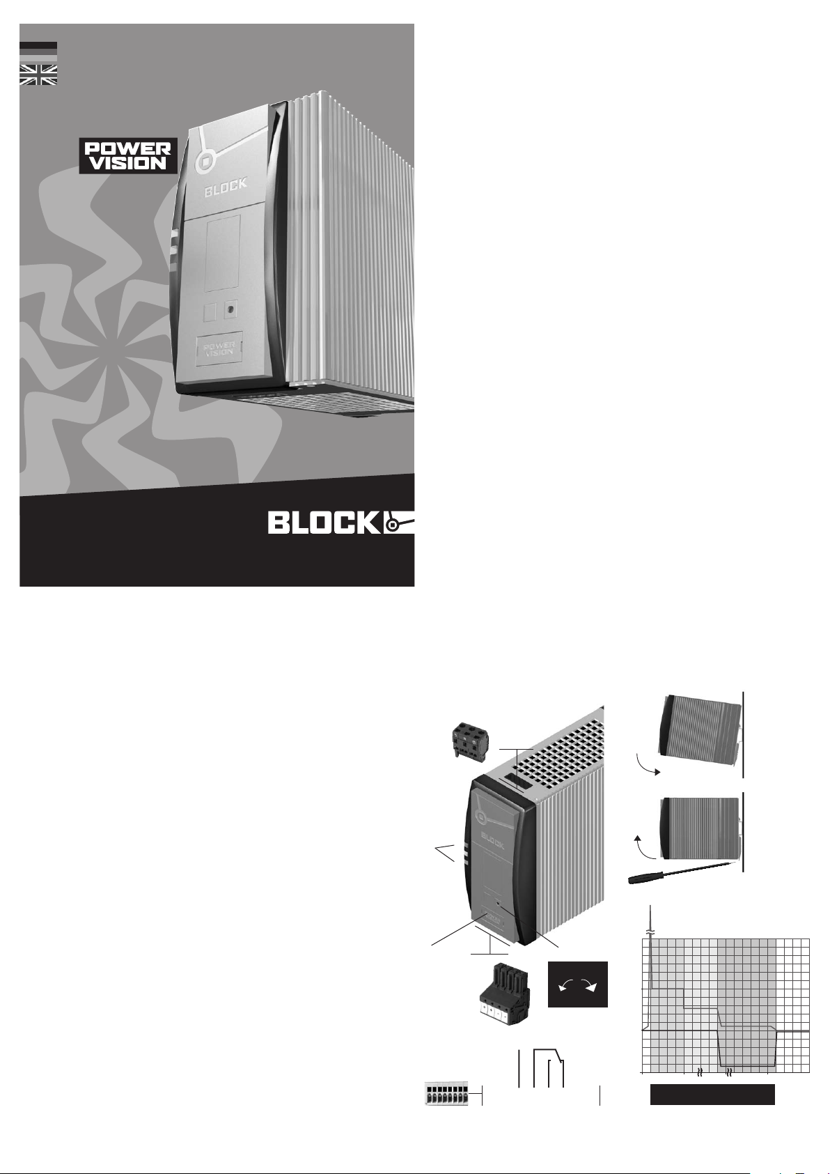
LED: Die grüne LED (a) leuchtet,
1
sofern die Ausgangsspannung größer
al s ca. 85 % der Au sga ngsn enn span nung ist. Die rote LED (b) leuchtet,
sofern die Ausgangsspannung kleiner
al s ca. 85 % der Au sga ngsn enn span nu ng is t .
Ausgangsspannung: Die Aus-
2
gangsspannung kann mit einem
Schraubendreher verändert werden.
Drehung im Uhrzeigersinn erhöht die
Ausgangsspannung. Drehung gegen
den Uhrzeigersinn verringert die
Ausgangsspannung.
Eingang (schwarzer Stecker) line
3
Ausgang (bla uer St e c ker ) load
4
Montage: Setzen Sie das Gerät mit
5
de r Trags c hie nenf ü hru n g an di e Ober ka n te der Trags c hie n e an un d rast e n
Si e es nac h unten ein.
Demontage: Ziehen Sie den
6
Schnappriegel mit Hilfe eines
Schraubendrehers auf und hängen
Sie das Gerät an der Unterkante der
Tragschiene aus.
Überstromverhalten: Real Power
7
Bo o st und Top Boos t . Bei Ku r zsc h lus s
eines Verbrauchers liefert die
Str o mve r sorg ung ei nen Top Boost
zum sicheren Schnellauslösen von Leitungsschutzschaltern. Für das Starten schwer anlaufender Lasten steht
ein 2stufiger dynamischer Power
Boost zur Verfügung. Bei vollständiger
Entnahme des Power Boostes für
8 Sekunden ist die Aktivierung eines
weiteren Boostes für 8 Sekunden
gesperrt. (Zwangspause)
Potenzialfreier Meldekontakt: Bei
8
Unterspannung am Ausgang wird das
interne Relais inaktiv. Diese Störung
kann über den Wechselkontakt abgefragt werden.
To re duce th e ri sk of mis tak in g the
terminals, the supplied terminals must
T
be used.
LED: The green LED (a) lights as soon
as the output voltage is larger than
approx. 85 percent of rated output
voltage. The red LED (b) lights if the
output voltage is lower than approx.
85 percen t of rated outpu t volta g e.
Output voltage: The output voltage
ca n be alt e r ed usi ng a sc r ewdr i ver. Turning the adjustment screw
clock wise raises the output voltage.
Tur ning the adj ust m ent sc r ew an t i clo ck w i se red uce the outpu t volta g e.
Input (bla ck pl u g) line
3
Output (b lue pl ug) load
Mounting: Place the unit with the DIN
5
rail guide on the upper edge of the DIN
rail, and snap it in with a downward
motion.
Removing: Pull the snap lever open
with the aid of a screwdriver and slide
the unit out at the lower edge of the
DIN rail.
Overload current behaviour: Real
7
Po w er Boo s t and Top Boos t . In the
event of a short circuit the power
supply is able to supply the top boost
mode, allowing high-speed magnetic
circuit breakers to operate safely. The
power supplies have an integrated 2
step Power Boost mode for starting
high load currents which prevents
the supply voltage failing completely.
The activation of a further boost is
prevented for 8 seconds after each
complete power boost. (compulsory
break)
Isolated signal contact: In the event
8
of undervoltage at the output, the
internal relay becomes inactive. This
er r or can be quer i ed via the cha nge o ver contact.
Stand-by-Eingang: Der St a nd- b y-
9 9
Eingang ermöglicht ein gezieltes
Ausschalten der Stromversorgung.
Durch das Anlegen einer externen
Gleichspannung am Stand-by-Eingang
wi r d der Au sga ng des Ge rät e s abge schaltet und die Stromversorgung
verbleibt im Bereitschaftszustand.
Ab bil du ng ze ig t den PVSE 230 /2 4- 10
Th is fi gu re sh ow s the PV SE 230 /2 4-10
line
3
L N PE
6
b
a
7
89
4
+ + – –
load
2
U
out
+–
Unenn
Urated
89
Optional
PV-CON
Stand-by
12345678
Relais akt iv (Kont akt 4-5 gesc hlossen),
we nn Uo ut > ty p. 0, 85 xU out .
Relay active (cont act 4-5 closed), if
Uout > typ. 0.85xUout.
Stand-by-input: The stand-by-input
allows targeted switch-off of the
power supply. By applying an external
DC voltage at the standby-input, the
output of the device is not released
and the power supply remains on
stand-by.
DI N 35 mm rai l
Top Boost
Strombegrenzung
[%]
out
I
Power
Boost
Stufe 1
Stufe 2
Step 1
Step 2
Überstromphase
Overcurrent phase
Current limitation
[V]
out
U
Inenn
Irated
t [sec]0
Page 2
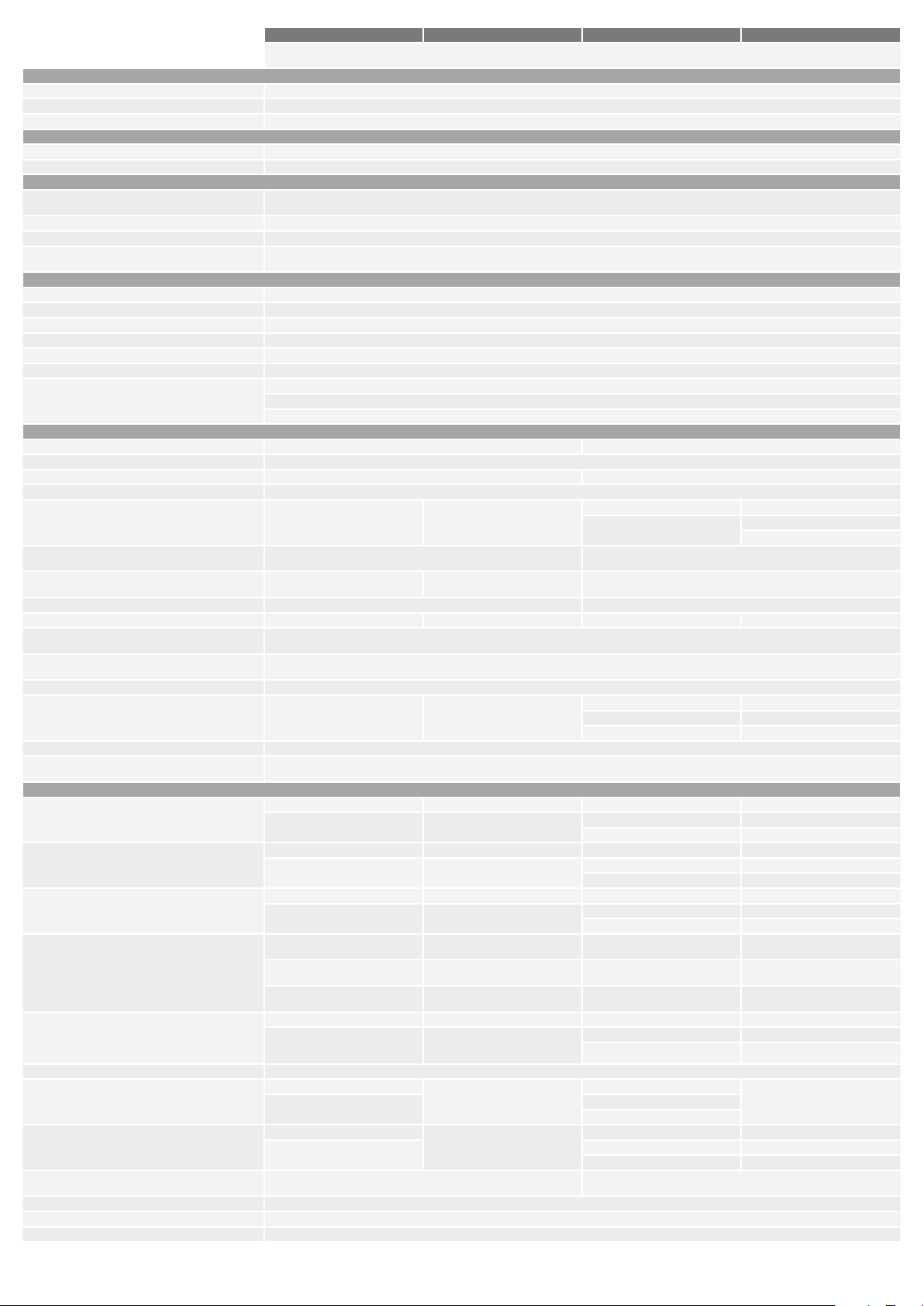
Technische Daten
Technical data
Normen S afet y standards
Sicherheit Safety EN 60950, UL 60950, UL 508
EMV EMC EN 61204-3 (Produktnorm) EN 61204-3 (product standard)
Schutzkleinspannung Saftety extra-low voltage EN 60950 (SELV) und EN 60204 (PELV) EN 60950 (SELV) and EN 60204 (PELV)
Zulassungen Approvals
UL UL UL/CSA 60950 recognised
UL UL UL 508 listed / CSA 22.2 No.107.1 3rd Ed. Listed
Umwelt Environment
Umgebungstemperatur Ambient temperature –25 °C … +70 °C, Derating: -3 %/K > +50 °C
Lagertemperatur Storage temperature –25 °C … +85 °C
Kühlart Cooling Selbstkühlung durch natürliche Konvektion bei vertikaler Einbaulage AN (Natural air convection cooling)
Zulässige Luftfeuchtigkeit Allowable humidity 30 bis 85% relative Feuchte, keine Betauung zulässig
Sicherheit und Schutz Safety and protection
Prüfspannung HV test voltage 4242 kVdc 4242 kVdc
Bauart Construction gekapselt, für den Einbau im Schaltschrank enclosed for installation in switching cabinets
Schutzart Protection index IP 20 (nach EN 60529) IP 20 (to EN 60529)
Schutzklasse Safety class vorbereitet für Geräte und Anlagen der Schutzklasse I prepared for safety class I
Anschlusskabel Conductors Zum Anschluss Kupferkabel mit min. 75 °C verwenden Use copper conductors only, rated 75 °C
Einsatzbereich Installation Einsatz in Bereichen mit Verschmutzungsgrad 2 For installation in pollution degree 2 environment
Rückspeisungsfestigkeit Feedback voltage max. 35 Vdc (bei DC 24 V -Typen) max. 35 Vdc (at DC 24 V -Types)
Eingan gsdaten Input
Eingangsnennspannung Rated input voltage 1~/2~ 100 – 240 Vac 1~/2~ 110 – 240 Vac
Eingangsspannungsbereich Operating input voltage range 85 - 264 Vac (120 - 373 Vdc)
Eingangsspannungsderating input voltage derating 5 %/Vac < 95 Vac 1,5 %/Vac < 110 Vac
Frequenzbereich Rated frequency range 50 – 60 Hz
Eingangsnennstrom bei 110 / 230 Vac (unter Nennlast)
Rated input current at 110 / 230 Vac (at nominal load)
Einschaltstrom (kalt)
In-rush current (cold)
Optionale aktive Einschaltstrombegrenzung
Active in-rush current limiter, optional
Aktive PFC Active PFC --- ja yes
Eingangssicherung intern Internal fuse 2 AT 4 AT 6,3 AT 10 AT
Externe Absicherung (UL-konform)
External protection device (UL-recognised)
Empfohlene externe Absicherung *
Recommended external protection *
Ableitstrom Leakage current typ. 1 mA
Netzausfallüberbrückung bei 110 / 230 Vac
Mains drop compensation at 110 / 230 Vac
Überspannungsschutz Over voltage protection durch Varistor im Primärstromkreis through varistor in primary circuit
Anschlüsse: WAGO Multisteckersystem
Terminals: WAGO multi connection system
Ausgangsdaten Output
Ausgangsnennspannung Rated output voltage 24 Vdc ±1 % (PVSE 230/24-3) 24 Vdc ±1 % (PVSE 230/24-5) 24 Vdc ±1 % (PVSE 230/24-10) 24 Vdc ±1 % (PVSE 230/24-20)
Ausgangsspannungsbereich Rated output voltage range 22 - 29,5 Vdc (PVSE 230/24-3) 22 - 29,5 Vdc (PVSE 230/24-5) 22 - 29,5 Vdc (PVSE 230/24-10) 22 - 29,5 Vdc (PVSE 230/24-20)
Ausgangsnennstrom Rated output current 3 Adc (PVSE 230/24-3) 5 Adc (PVSE 230/24-5) 10 Adc (PVSE 230/24-10) 20 Adc (PVSE 230/24-20)
Power Boost 6 Adc / 4 s (4,5 Adc / 8 s)
Top Boost für 25 ms Top Boost for 25 ms 14 A (PVSE 230/24-3) 21 A (PVSE 230/24-5) 60 Adc (PVSE 230/24-10) 80 Adc (PVSE 230/24-20)
Strombegrenzung Current limitation typ. 1,1 x INENN typ. 1.1 x Irated
Wirkungsgrad Efficiency 87,8 % (PVSE 230/24-3) 87,8 % 90 % (PVSE 230/24-10) 91 %
max. Verlustleistung Leerlauf / Nennlast
ma x. P ow er l oss idl ing / no m in a l l o ad
Leistungsaufnahme im Stand-by-Betrieb
Power consumption in stand-by-operation
Restwelligkeit Residual ripple typ. 70 mVpp
Parallelschaltbarkeit Parallel operation ja, zur Leistungserhöhung yes, for increased power
Reihenschaltbarkeit Serial operation ja, zur Spannungserhöhung yes, for increased voltage
12 Vdc ±1 % (PVSE 230/12-6) 12 Vdc ±1 % (PVSE 230/12-10) 12 Vdc ±1 % (PVSE 230/12-15) 30 Vdc ±1 % (PVSE 230/30-15)
11 - 18 Vdc (PVSE 230/12-6) 11 - 18 Vdc (PVSE 230/12-10) 11 - 18 Vdc (PVSE 230/12-15) 27 - 43 Vdc (PVSE 230/30-15)
70 W 120 W 180/24 0 W 450/480 W
0,86 / 0,51 Aac 1,7 / 0,97 Aac 1,9 / 0,9 Aac (180 W Type) 5,1 / 2,3 Aac (PVSE 230/24-20)
<5 Ap, aktiv
<5 Ap, active
10 / 70 ms 12 / 35 ms 20 / 20 ms (PVSE 230/24-10) 25 / 25 ms (PVSE 230/24-20)
6 Adc (PVSE 230/12-6) 10 Adc (PVSE 230/12-10) 15 Adc (PVSE 230/12-15) 15 Adc (PVS E 230/30-15)
(PVSE 230/24-3)
12 Adc / 4 s (9 Adc / 8 s)
(PVSE 230/12-6)
21 A (PVSE 230/12-6) 60 A* (PVSE 230/12-10)
83 % (PVSE 230/12-6) 87 % (PVSE 230/12-15)
3,0/8,8 W (PVSE 230/24-3) 5,0/14,6 W 3,8/24 W (PVSE 230/24-10) 4,8/43,2 W (PVSE 230/24-20)
3,0/9,4 W (PVSE 230/12-6) 4,6/23,4 W (PVSE 230/12-15) 4,8/40,2 W (PVSE 230/30-15)
Einphasige, primär getaktete Einbaustromversorgung für TH35-Tragschienenmontage
Single phase, primary switched mode power supply component for mounting on DIN 35 mm rails
Anlauf bei -40 °C typgeprüft Device start at -40 °C type-tested
30 to 85% relative humidity with no dew
max. 25 Vdc (bei DC 12 V -Typen) max. 25 Vdc (at DC 12 V -Types)
max. 63 Vdc (bei DC 30/48 V -Typen) max. 63 Vdc (at DC 30/48 V -Types)
2,5 / 1,2 Aac (240 W Type) 4,7 / 2,1 Aac (PVSE 230/30-15)
<30 Ap, NTC
<8 Ap, aktiv
<8 Ap, active
nicht erforderlich
Leitungsschutzschalter 6 A, 10 A oder 16 A, Charakteristik B, C
10 Adc / 4 s (7,5 Adc / 8 s)
(PVSE 230/24-5)
20 Adc / 4 s (15 Adc / 8 s)
(PVSE 230/12-10)
* 40 A bei Uin < 110 Vac
* 40 A at Uin < 110 Vac
0,5 W 0,8 W
not necessary
Circuit breakers 6 A, 10 A or 16 A
30 / 30 ms (PVSE 230/12-15) 28 / 28 ms (PVSE 230/30-15)
20 / 20 ms (PVSE 230/48-5) 20 / 20 ms (PVSE 230/48-10)
WAGO Serie 231, max 2,5 mm²
WAGO series 231, max. 2.5 mm²
48 Vdc ±1 % (PVSE 230/48-5) 48 Vdc ±1 % (PVSE 230/48-10)
33 - 52 Vdc (PVSE 230/48-5) 33 - 52 Vdc (PVSE 230/48-10)
5 Adc (PVSE 230/48-5) 10 Adc (PVSE 230/48-10)
20 Adc / 4 s (15 Adc / 8 s)
(PVSE 230/24-10)
30 Adc / 4 s (22,5 Adc / 8 s)
(PVSE 230/12-15)
10 Adc / 4 s (7,5 Adc / 8 s)
(PVSE 230/48-5)
55 Adc (PVSE 230/12-15) 70 Adc (PVS E 230/30-15)
30 Adc (PVSE 230/48-5) 60 Adc (PVSE 230/48-10)
91 % (PVSE 230/48-5)
7,4/21,6 W (PVSE 230/48-5) 4,8/43,2 W (PVS E 230/48-10)
<8 Ap, aktiv
<8 Ap, active
---
5,1 / 2,3 Aac (PVSE 230/48-10)
30 Adc / 4 s (25 Adc / 8 s)
(PVSE 230/24-20)
22 Adc / 4 s (18,5 Adc / 8 s)
(PVSE 230/30-15)
17,5 Adc / 4 s (15 Adc / 8 s)
(PVSE 230/48-10)
Page 3
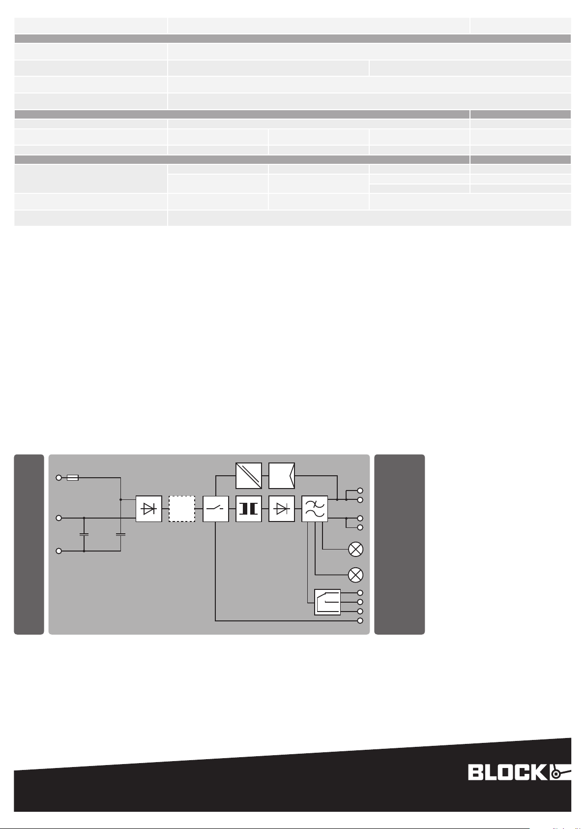
Anschlüsse: WAGO Multisteckersystem
Terminals: WAGO multi plug system
Signalisierung Signaling
Power Good (DC OK), LED Uout > 0,85 x Unenn: LED grün leuchtet, LED rot aus
Po we r Go od ( DC O K), pot en zia l fr ei
Power Good (DC OK), potential-free
St and- by-E in ga ng
Stand-by-input
Anschlüsse: WAGO Multisteckersystem, optional
Terminals: WAGO multi plug system, optional
Mechanische Daten Mechanical data
Befestigung Mounting Tragschienenmontage mit zwei Montagemöglichkeiten rail mounting with two possible varieties
Maße B x H x T **
Dimensions width x height x depth **
Gewicht Weight 0,8 kg 0.8 kg 1,1 kg 1.1 kg 1,3 kg 1.3 kg 2,3 kg 2.3 kg
Bestellnummern Order numbers
Standard standard PVSE 230/24-3 (DC 24 V) PVSE 230/24-5 (DC 24 V) PVSE 230/24-10 (DC 24 V) P V S E 2 3 0 /2 4- 2 0 ( D C 2 4 V )
mit aktiver Einschaltstrombegrenzung
with active in-rush current limiter
Ans chluss tecker für S ign ali sie rung
connector for signaling
* Für DC Eingangsspannung ist eine geeignete DC- Sicherung erforderlich.
* For DC input voltage suitable DC fuse required.
** Maße ohne Anschlussstecker, Tiefe T ab Oberkante Tragschiene.
** Dimensions without terminals, depth from upper edge of DIN rail.
*** WAGO Serie 831: Mit Aderendhülse max. 6 mm². Bei feindrähtigen Leitern bitte geeigneten Spleißschutz verwenden.
*** WAGO series 831: With ferrule max. 6 mm². Please use suitable anti-splaying method for fine-stranded conductors.
Relaiskontakt, Typ: Wechsler, 30 Vdc/1 A (nach UL: 24 Vdc / 24 mA)
relay contact, type: switch over, 30 Vdc/1 A (at UL: 24 Vdc / 24 mA)
40 x 127 x 163 mm 57 x 127 x 163 mm 57 x 127 x 179 mm 97 x 127 x 187 mm
PVSE 230/12-6 (DC 12 V) PVSE 230/12-10 (DC 12 V) PVSE 230/12-15 (DC 12 V) PVSE 230/30-15 (DC 30 V)
PVSE 230/24-3B (DC 24 V) PVSE 230/24-5B (DC 24 V) ---
Serie 231 max. 2,5 mm²
series 231 max. 2.5 mm²
Uout > 0.85 x Urated: LED green lights, LED red off
a kt i v be i 10 . .. 2 8, 8 Vd c
active at 10 ... 28.8 Vdc
Serie 733 max. 0,5 mm²
series 733 max. 0.5 mm²
Relaiskontakt, Typ: Wechsler, 30 Vdc/1 A (nach UL: 24 Vdc / 24 mA)
relay contact, type: switch over, 30 Vdc/1 A (at UL: 24 Vdc / 24 mA)
PVSE 230/48-5 (DC 48 V) PVSE 230/48-10 (DC 48 V)
PV-CON
Serie 831 max. 10 mm² ***
series 831 max. 10 mm² ***
Funktionsschaltbild
Functional diagram
L (–)
Active
Active
PFC*
N (+)**
PE
* ab 180 W Type
* from 180 W type
** Zweiphasenbetrieb nur möglich, sofern die maximale Eingangsspannung von 264 Vac nicht überschritten wird.
** Two phase operation only possible, if input voltage under 264 Vac.
PFC
–
–
+
+
LED (Green):
DC OK
LED (Red):
DC NOT OK
DC OK
Stand-by
Technische Änderungen vorbehalten.
Subject to change.
BLOCK Transformatoren-Elektronik GmbH
Max-Planck-Straße 36-46 . 27283 Verden, Germany
[email protected] . block.eu
block.eu
 Loading...