

Page 1
deutsch / english
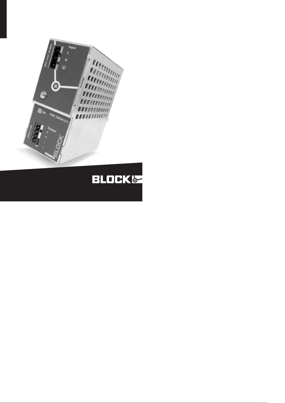
PSR 230/24-2,5
Primär getaktete Gleichstromversorgung
Primary Switch-Mode Power supply
block-trafo.de
1.3 Installation und
Inbetriebnahme
1.3 Installation and Operation
Das Betriebsmittel ist vor unzulässiger
Beanspruchung zu schützen. Insbesondere
dürfen bei Transport und Handhabung
keine Bauelemente verbogen und/oder
Isolationsabstände verändert werden.
Die Berührung elektrischer Bauelemente
und Kontakte ist zu vermeiden. Den geforderten Mindestabstand zu benachbarten
Teilen unbedingt einhalten um die Kühlung
nicht zu behindern! Während des Betriebes
kann das Betriebsmittel (entsprechend
der Schutzart) heiße sowie blanke spannungsführende Oberflächen besitzen. Das
Betriebsmittel immer im spannungsfreien
Zustand montieren und verdrahten. Die
Produktbeschreibung und die technischen
Hinweise in unserem Hauptkatalog sowie
die Aufschriften am Betriebsmittel und
auf dem Typenschild sind zu beachten. Die
Installation ist entsprechend den örtlichen
Gegebenheiten, einschlägigen Vorschriften
(z.B. VDE0100), nationalen Unfallverhü-
www.block-trafo.de
tungsvorschriften (z.B. UVV-VBG4 bzw.
BGV A3) und den anerkannten Regeln der
Technik durchzuführen. Dieses elektrische
Betriebsmittel ist eine Komponente, die
zum Einbau in elektrische Anlagen oder
Maschinen bestimmt ist und erfüllt die Anforderungen der Niederspannungsrichtlinie
(2006/98/ EWG). Bei Einbau in Maschinen
ist die Aufnahme des bestimmungsgemäßen Betriebes solange untersagt, bis
PSR 230/24-5 2009•07
festgestellt wurde, dass die Maschine den
Bestimmungen der Maschinenrichtlinie
(2006/42/EWG) entspricht; EN 60204
ist zu beachten. Die Aufnahme des bestimmungsgemäßen Betriebes ist nur bei
Einhaltung der EMV-Richtlinie (2004/108/
EWG) erlaubt. Die Einhaltung der durch
die EMV-Gesetzgebung geforderten
Grenzwerte liegt in der Verantwortung des
Herstellers der Anlage oder Maschine.
1.4 Wartung und
Instandhaltung
1.4 Maintenance and
Servicing
Elektrische Betriebsmittel bedürfen in der
Regel keiner besonderen Wartung, sind
jedoch (entsprechend der Schutzart) vor
Staubablagerung, Feuchte, Strahlung und
aggressiven Chemikalien zu schützen. Die
Instandsetzung ist nur im Rahmen der in
dieser Gebrauchsanleitung aufgeführten
Maßnahmen statthaft. Sollte es trotzdem
einen Ausfall geben, schicken Sie bitte
das Betriebsmittel zur Reparatur an uns
ein. Geben Sie bitte an: Art des Fehlers,
Begleitumstände (Einsatzbedingungen),
eigene Vermutungen über die Fehlerursache, vorausgegangene ungewöhnliche
Vorkommnisse usw.
Electrical equipment generally requires no
special maintenance. However (depending
on the protection index) they have to be
protected against dust build-up, moisture,
radiation and aggressive chemicals.
Servicing is only permitted under the
terms and conditions of these operating
instructions. Nevertheless should a failure
occur, please return the equipment to us
for repair, giving the following information:
Type of fault, accompanying symptoms
(operation conditions), your own
speculation as to the cause of the failure,
previous unusual conditions, etc.
1. Sicherheits- und
Anwendungshinweise
1. Safety and User
Information
Wir beglückwünschen Sie zum Erwerb
dieses hochwertigen Produktes. In dem
beschriebenen Anwendungsbereich wird
es im bestimmungsgemäßen Betrieb
lange seine Funktion erfüllen. Wie bei
jedem technischen Produkt kann jedoch
die Gefahr von schweren Personen- oder
Sachschäden bei unsachgemäßem Einsatz,
unzulässigem Entfernen von erforderlichen
Abdeckungen, bei falscher Installation oder
Bedienung bestehen. Folgen Sie dieser Gebrauchsanleitung und verfahren Sie nach
den anerkannten Regeln der Technik. Alle
Arbeiten zur Installation, Inbetriebnahme
und Betrieb sowie zur Instandhaltung sind
von qualifiziertem Fachpersonal auszuführen (IEC 60364, VDE0105).
Congratulations to the ownership of this
high quality product. A long
life expectancy is assured if used in the
described manner and correct application.
As with all technical products, a hazard to
health or equipment can exist if improperly
use, an unauthorized removal of necessary
covers, incorrect installation or incorrect
operation is present. Follow these
instructions and adhere to the generally
accepted rules of technology. Installation
and setting up should only be carried out
by qualified personal (IEC 60364, VDE
0105).
1.1 Verpackung
1.1 Packaging
Bitte untersuchen Sie das Betriebsmittel
sofort auf Transportschäden wie Deformation und lose Teile. Beschädigungen bitte
unverzüglich beim Transportunternehmen
reklamieren; auch wenn die Verpackung
äußerlich nicht beschädigt ist.
Carefully check the equipment immediately
after receipt, for transport damage,
deformation and loose parts. Any damage
should be reported without delay to the
transport carrier, even then when no
apparent damage to external packing is
visible.
1.2 Lagerung
1.2 Storage
zulässige Lagerungstemperatur:
-25°C ... +85°C
zulässige Luftfeuchtigkeit:
30 … 85% relative Feuchte keine
Betauung zulässig
Bei Langzeitlagerung:
Betriebsmittel mit eingebauten
Kondensatoren sind mindestens
alle 2 Jahre für 5 Minuten an
Netzspannung anzulegen.
Permitted storage temperature:
-25°C ... +85°C
Permitted humidity:
30 ... 85% relative humidity Residual
humidity is not permitted.
Extended storage:
Equipment containing capacitors
should be connected to the mains
supply for at least 5 minutes every
two years.
This equipment has to be protected
against improper use. Components are
not to be bent or isolation spacing to be
changed, when transported or handled.
The contact with electrical components
and terminals has to be avoided.
Always disconnect the equipment from the
mains supply before installation or wiring
has started!
During operation this equipment can
have (depending on the protection index)
hazardous live parts or hot surfaces.
The product description, the technical
information in our main catalogue and
the marking on the equipment and rating
plate have to be observed. The installation
must be carried out according to the
prevailing local conditions, prevailing
safety standards (i.e. VDE 0100), national
accident preventions (i.e. UVV-VBG 4;
BGV A2 respectively) and the generally
accepted rules of technology. This
equipment is a component designed for
installation into electrical installations or
machines, and fulfils the requirements
of the low voltage guidelines (73/23/
EWG). When installed into machinery, the
normal operation is forbidden until it is
determined that the machine fulfils the
requirements of the machinery guidelines
(89/392/EWG); attention must be paid
to EN 60204. Normal operation in the
intended use can only begin when the EMC
guidelines (89/336/EWG) are fulfilled. The
observance of the required limitations for
the EMC legislation is the responsibility
of the manufacturer of the installation or
machinery.
1.5 Entsorgung
1.5 Disposal
Bitte beachten Sie die aktuellen
Bestimmungen und entsorgen Sie je nach
Beschaffenheit z.B. Elektronikschrott
(Leiterplatten), Kunststoff (Gehäuse),
Blech, Kupfer, usw.
Please observe the current regulations
and dispose according to type of material
i.e. electronic scrap (printed circuit
boards), plastics (housing), steel, copper,
etc.
1.6 Änderungen
1.6 Amendments
Unser Haus hat die Produktdokumentation
mit großer Sorgfalt erstellt und geprüft. Es
kann jedoch keine Gewährleistung bezüglich der Fehlerfreiheit und Vollständigkeit
übernommen werden. Eine Übertragbarkeit der Angaben auf die jeweilige Anwendung ist zu prüfen. Die technischen Daten
beschreiben die Eigenschaften des Produktes, ohne diese zuzusichern. Änderungen,
die dem technischen Fortschritt dienen,
sind vorbehalten.
We have produced this documentation
with the utmost care; however no
guarantee for completeness can be given.
The adoption of this information in an
application must be individually checked.
The technical details describe the product
features without guaranteeing these. This
product is subject to changes that serve
the technical advancement.
Page 2

2. Einsatzgebiet
2. Application
Diese getaktete Gleichstromversorgung
ist eine einstellbare Einspannungsversorgung in Primärschaltreglertechnik. Die Einbaukomponente ist zur Energieversorgung
von industriellen elektrischen und elektronischen Verbrauchern der Informationstechnik (IT), der Automatisierungstechnik,
des Anlagenbaus, der Verfahrenstechnik
und der Steuerungstechnik geeignet.
This power supply is an adjustable single
phase, primary switched mode voltage
regulated unit. It is suitable for the supply
of industrial electronical applications of the
information technology (IT), automation,
process and control technology.
3. Normen
3. Standards
Die elektrische Sicherheit und EMV
(Elektromagnetische Verträglichkeit) ist
durch den Geräteaufbau entsprechend
den angeführten Normen gegeben. Das
Betriebsmittel entspricht den gesetzlichen
Anforderungen und Normen zur CE-Konformität und trägt das CE-Zeichen.
The electrical safety and EMC
(electromagnetical compability) is given
through the construction to safety
standards. The requirements for CE
conformity are given and the equipment is
CE marked.
5. Montagehinweise
5. Mounting Information
Das Betriebsmittel ist auf Tragschienen
TH35 nach EN 60715 aufrastbar. Das
Gerät ist zwecks ordnungsgemäßer
Entwärmung horizontal zu montieren.
Abweichende Einbaulagen geschehen
auf eigene Gefahr. Wir empfehlen hierbei
eine Ausgangsleistung von 50% und eine
Umgebungstemperatur von 45°C nicht zu
überschreiten. Die Mindestabstände sind
einzuhalten.
The power supply unit is designed for
mounting rails TH35 in acc. with EN
60715. For appropriate cooling the device
has to be mounted in horizontal direction.
Other mounting directions are on the
users own risk. In case of other mounting
directions than horizontal we recommend
not to exceed 50% of the rated output
power and 45°C ambient temperature.
Minimum clearances have to be observed.
5.1 Anschlüsse
5.1 Connections
Überprüfen Sie vor Anschluss des Betriebsmittels die zugehörige Betriebsspannung (siehe Typenschild).
Before connection to mains, check for the
correct supply voltage (see rating plate).
6. LED
6. LED
Eine grüne LED dient als Ausgangsspannungsindikator [OK].
A green LED for output voltage indication
[OK].
7. Einstellen der
Ausgangsspannung
7. Adjustment of the
Output Voltage
Mit dem unterseitigen Trimmpotentiometer kann von außen die Ausgangsspannung
von 22,0Vdc bis 28,8Vdc eingestellt
werden.
The output voltage can be set with the
adjustable potentiometer on the bottom
side, for any output voltage from 22.0Vdc
to 28.8Vdc.
8. Parallelschaltbarkeit
8. Parallel Connectivity
Beim Parallelbetrieb ist die Ausgangsspannung der parallel zu schaltenden Geräte
möglichst exakt auf den gleichen Wert
einzustellen. Ferner müssen die Leitungswiderstände von den Netzteilen zur Last
nahezu gleich sein. Zum Parallelschalten
dürfen nur Geräte gleicher Leistung verwendet werden.
When connecting power supplies in
parallel it is necessary to adjust the output
voltages pretty exact at the same level.
Furthermore the wire resistance from
each power supply to the load has to be
nearly the same. For parallel connecting
use only power supplies with the same
output power.
4. Betriebshinweise
4. Operation Information
Die Kühlung des Betriebsmittels darf nicht
beeinträchtigt werden. Eine ungehinderte
Luftzufuhr und ein Mindestabstand von
15mm zu benachbarten Teilen sind sicherzustellen. Die Verdrahtung der Anschlussklemmen darf nur im spannungsfreien
Zustand erfolgen. Aufgrund der Schutzart
IP 20 ist der Betrieb des Betriebsmittels
nur in trockenen Räumen zulässig.
The adequate cooling and air circulation
must be guaranteed and the mounting is
only permitted on a horizontal mounting
rail. A distance of 15mm (left/right) and
70mm (above/below) to neighbouring
components must be observed.
The wiring of the connection terminals is
only permitted when the supply voltage is
disconnected. Due to the protection index
IP20, the use of the equipment is only
permitted in dry areas.
5.2 Anschlussklemmen
5.2 Connection Terminals
Der Anschluss der Versorgungsleitungen
erfolgt auf der Primär- u. Sekundärseite
mit Steckverbindern WAGO MULTISTEKKERSYSTEM Serie 231. Primärseitig ist
der schwarze Steckverbinder für die Anschlüsse L, N u. PE vorgesehen. Sekundärseitig sind je zwei blaue Klemmstellen für
und vorhanden.
Mains and load are connected via
pluggable connectors with WAGO MULTI
CONNECTION SYSTEM Series 231
terminals. The black connector with Phase
(L), Neutral (N) and Protective Earth (PE)
terminals are used for connecting the
power supply unit with the mains. The
blue connector provides two terminals for
each load output and plus one shield
connection.
5.3 Verbindungskabel
5.3 Connection Cables
Die Steckverbinder WAGO MULTISTEKKERSYSTEM Serie 231 sind für Einzeladern bis zu 2,5mm² (starr oder flexibel)
geeignet. Bei der Dimensionierung der
Leiterquerschnitte ist der mögliche Ausgangsstrom mit ca. 1,2 x I Bemessung zu
beachten.
The WAGO MULTI CONNECTION SYSTEM
Series 231 allows wiring with solid or
stranded wires; cross sections up to AWG
14/2.5mm². The cross section of the
wiring must be adequate to 1.2 x of the
designated output current.
9. Kurzschluss- und
Überlastverhalten
9. Short-Circuit and Overload
Behaviour
Der Ausgang des Betriebsmittels ist
elektronisch vor Überlast und Kurzschluss
geschützt. Die Ausgangsspannung wird
bis zu einem Ausgangsstrom von 1,1 x I
Bemessung konstant beim eingestellten
Wert gehalten (siehe Abb. 2).
The output circuit of this equipment is
electronically protected against shortcircuit and overload. The output voltage
setting will be held to a constant value up
to 1.1 x I Rated. The output voltage will be
reduced, if the output current is above 1.1
x I Rated (see Fig. 2).
10. Derating-Kurve
10. Derating Curve
Bei ständiger Überlast schaltet das
Betriebsmittel durch den thermischen
Überlastschutz ab und nach Abkühlung
selbsttätig wieder ein.
In continuous overload condition, the
power supply switches off.
After cooling down it starts automatically.
Page 3
11. Technische Daten
Eingang (ac in)
U in: AC Bemessungswert: 100-240Vac
DC Bemessungswert: 140-300Vdc
Bereich: 90-264Vac
130-300Vdc
Frequenz: 50Hz-60Hz
I in: Bemessungswert: 0,6A bei 230Vac
Ableitstrom: typ. 700μA
Einschaltstrom: <50Ap
Netzausfallüberbrückung: >20ms
Ausgang (dc out)
U out: Bemessungswert: 24Vdc
Bereich: 22,0-28,8 Vdc einstellb.
voreingestellt auf: 24 Vdc
Regelgenauigkeit: 2%
Rippel: <100mVpp (bis zu
20MHz)
I out: 2,5A (Abb. 2)
Strombegrenzung: ab 1,1 x I Bemessung
Verhalten bei Überlast: siehe Abb. 2
Wirkungsgrad/Verlustleistungen
Wirkungsgrad: typ. 90%
Verlustleistung: typ. 7W (230Vac/24Vdc 2,5A)
Verlustleistung max.: typ. 8W (90Vac/24Vdc 2,5A)
Absicherung
Interne Absicherung: 1,6AT/250Vac
Empfohlene Vorsicherung: Leitungsschutzschalter
C10 bzw. B16
für DC Eingangsspannung ist eine externe DC Sicherung
erforderlich
Transientenüberspannungsschutz: Varistor
Eingangs-Anschlussleitungen (in: L,N und PE)
WAGO MULTISTECKERSYSTEM Serie 231, 3-pol., schwarz
Leiterart: Voll- oder Litzendraht
Querschnitt: 0,08-2,5mm²/AWG 28-14
Abisolierlänge: 8-9mm/0,33 inch
Ausgangs-Anschlussleitungen (out: 2x und 2x )
WAGO MULTISTECKERSYSTEM Serie 231, 4-pol., blau
Leiterart: Voll- oder Litzendraht
Querschnitt: 0,08-2,5mm²/AWG 28-14
Abisolierlänge: 8-9mm/0,33 inch
11. Technical Specifications
Line in (AC in)
Voltage in: Rated AC voltage: 100-240Vac
Rated DC voltage: 140-300Vdc
Voltage Range: 90-264Vac
130-300Vdc
Frequency: 50Hz-60Hz
Current in: Rated current: 0.6A at 230Vac
Leakage current: typ.700μA
Inrush current: <50Ap
Mains failure hold up time: >20ms
Output (DC out)
Voltage out: Rated voltage: 24Vdc
Voltage range: 22.0-28.8Vdc
adjustable
Preset to: 24.0Vdc
Tolerance: 2%
Residual ripple: <100mVpp (up to
20MHz)
Current out: 2,5A (Fig. 2)
Current limitation: over 1.1x I Rated
Behaviour with overload: see Fig. 2
Efficiency/Power Losses
Efficiency: typ. 90%
Power Losses: typ. 7W (230Vac/24Vdc 2,5A)
Power Losses max.: typ. 8W (90Vac/24Vdc 2,5A)
Device Protection
Internal Fuse: 1,6AT/250Vac
Recommended backup fuse: circuit-breaker C10 resp. B16
for DC input voltage, an external DC fuse is necessary
Transient surge voltage protection: varistor
Input Connections (in: L,N and PE)
WAGO MULTI CONNECTION SYSTEM
Series 231, 3-pole, black
Type of wires: solid and stranded
Cross Section: AWG 28-14/0.08-2.5mm²
Stripped length: 0.33inch/8-9mm
Output Connections (out: 2x and 2x )
WAGO MULTI CONNECTION SYSTEM
Series 231, 4-pole, blue
Type of wires: solid and stranded
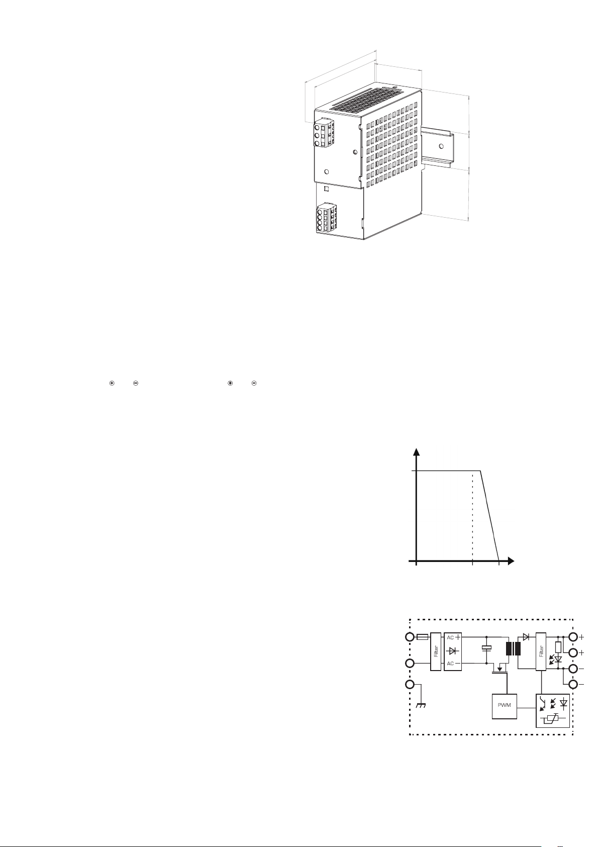
Maße auf Tragschiene TH35
Abb. 1
Dimensions on Mounting Rail TH35
Fig. 1
133
115
50,5
Die Stromversorgung wird mit dem an der
Rückseite eingesetzten Schieber auf dem
oberen Schenkel der Tragschiene TH35
angegesetzt. Die Aufrastung erfolgt durch
Drücken der Stromversorgung in Richtung
Tragschiene.
Place the unit with the steel catch at an
angle behind the top edge
of the mounting rail TH35. Press the unit
until it latches behind the
lower edge of the mounting rail.
373546
Abmessungen und Gewicht
B x H x T: 51 x 128 x 141* mm
* incl. Anschlusssteckern
Gewicht: 675g
Umgebungstemperatur / Luftfeuchtigkeit
Betrieb: -10°C ... +70°C/30-85% RH
ohne Betauung
Derating: -3%/K >+50°C
Verschmutzungsgrad: 2 (nach EN 50178)
Klimaklasse: 3K3 (nach EN 60721)
Kühlung
Die Gehäuseoberfläche darf nicht wärmer als +80°C
werden.
Empfohlener Freiraum bei natürlicher Konvektion und
horizontaler Einbaulage: links/rechts: 15mm
oben/unten: 70mm
Sicherheit und Schutz
Schutzklasse: vorbereitet für Schutzklasse I
Schutzart: IP 20 nach EN 60529
Überspannugsschutz: max. 40Vdc
Überlastschutz: durch Strombegrenzung
kurzschlussfest: bei ca. 2 x I Bemessung
leerlauffest: ja
rückspeisefest: max. 30Vdc
SELV: IEC/EN 60950-1
PELV: EN 60204-1, EN 50178,
IEC 62103, IEC 60364-4-41
Cross Section: AWG 28-14/0.08-2.5mm²
Stripped length: 0.33inch/8-9mm
Dimensions / Weight
W x H x D: 51mm x 128mm x 141*mm
*with terminals
Weight: 675g
Environmental Conditions
Operation: -10°C ... +70°C/30-85% RH
without dewfall
Derating: -3%/K >50°C
Contamination class: 2 (in acc. with EN 50178)
Climatic class: 3K3 (in acc. with EN 60721
Cooling
The housing surface temperature shall not exceed +80°C.
The recommended spacing with natural convection and
horizontal mounting: left/right: 15mm
above/below: 70mm
Safety/Protection
Safety class: prepared for safety class I
Protection index: IP 20 to EN 60529
Over voltage protection: max. 40Vdc
Over load protection: current limited
Short circuit proof: at approx. 2 x I Rated
No load operation: yes
Feedback protection: max. 30Vdc
SELV: IEC/EN 60950-1
PELV: EN 60204-1, EN 50178,
IEC 62103, IEC 60364-4-41
Ausgangskennlinie
Abb. 2
Output Characteristic
Fig. 2
Blockdiagramm
Abb. 3
Block Diagram
Fig. 3
Ua(Vdc)
24
0
Ausgangsstrom
output current
L
N
PE
max. Ausgansleistung 120W
max. output power 120W
5,0 9,0 Ia(Adc)0
F
LED
dUa
Page 4

12. Zulassungen
12. Approvals
UL 60950 EMC
CSA C22.2 Störaussendung:
Emission:
No. 60950-1-03 EN 61000-6-3
E213214
Störfestigkeit:
Immunity:
EN 61000-6-2
UL 508
CSA C 22.2
No. 14-95
E219022
12. Zulassungen/Normen
EN 61204-3 UL 60950 Germanischer Lloyd
EN 60950 UL 508
EMV: EN 61000-6-3
EN 61000-6-2 W o
BLOCK Transformatoren-Elektronik GmbH
Max-Planck-Straße 36-46 . 27283 Verden, Germany
[email protected] . www.block-trafo.de
block-trafo.de
 Loading...