

Block ESG 3, ESG 4, ESG 5 User guide [de]
Safety and User Information
Congratulations to the ownership of this high quality product. A
long life expectancy is assured if used in the described manner
and correct application. As with all technical products, a hazard
to health or equipment can exist if improperly used, an unauthorized removal of necessary covers, an incorrect installation or an incorrect operation is present. Follow these instructions and adhere to the generally accepted rules of technology. Installation and setting-up should only be carried out by
qualified personal (IEC 60364 / VDE 0105).
Packing
Please check carefully the equipment immediately after receipt,
for transport damage as deformation, breakage or loose parts.
Any damage should be reported without delay to the transport
carrier, even if no apparent damage to external packing is visible.
Storage
Permitted Storage Temperature -25°C...+85°C
Permitted Humidity 30%...80% relative humidity
Extended Storage Equipment containing capa citors: should be connected
to the mains supply for at
least 5 minutes every two
years.
Installation and Operation
This equipment is protected against improper use. The contact
with electrical components and terminals should be avoided.
The product description, the technical information in our main
catalogue and the marking on the equipment are to be observed. The installation must be carried out according to the
prevailing local conditions, prevailing safety standards (e.g.
VDE 0100), national accident preventions (e.g. UVV-VBG 4;
BGV A2 respectively) and the generally accepted rules of technology.
Maintenance and Servicing
This equipment usually requires no special maintenance, however (depending on the protection index) it must be protected
against aggressive chemicals, moisture, dust and radiation.
Servicing is only permitted under the terms and conditions of
these operating instructions. Nevertheless should a failure
occur, please return the equipment to us for repair. Please give
us the following information: Type of fault, accompanying symptoms (operating conditions), your own speculation upon the
cause of the failure, previous unusual conditions, etc.
Disposal
Please observe the current regulations and dispose according
to type of material, e.g. as electronic scrap (printed circuit
boards), plastics (housing), steel, copper, etc.
Residual humidity is not per mitted.
6 7 8 1
Amendments
We have produced this documentation with the utmost care; however no guarantee in terms of correctness and completeness can
be given. The adoption of this information in an application must
be individually checked. The technical details describe the product
features without guaranteeing these. This product is subject to
changes that serve the technical advancement.
Description and Application
On physical condition, during power-up of certain loads, the automatic circuit breaker or the motor circuit switch could shut off. The
Inrush Current Limiter prevents this. It can power-up and supply a
load up to max. 16A. The Inrush Current Limiter is insetted in the
load line. It has an intrinsic resistance (limiting resistance) of typ.
7.8 Ω, which is in series connection with the load. Therefore it can
flow an inrush current of max. 29.5A at 230Vac (because of the impedances of mains and loads, the real inrush current is usually lower). Normally the switch-on peaks are decreased after some periods and the build-in power-relay bridges the intrinsic resistance of
the Inrush Current Limiter. Now the load is directly connected with
the mains. The Inrush Current Limiter operates mainly currentleaded and partly time-leaded, i.e. the load current is continuously
controlled. Below a minimum load of typ. 20W, open-circuit is detected and the limiting resistance is switched in the circuit permanently. On higher wattage the limiting resistance is bridged; in this
case the inrush current cannot be limited. The period of inrush
current limiting is max. 300ms; depending on the load it will
reduced to min. 60ms. At the power-up moment of the Inrush
Current Limiter there is a defined limiting time of 150ms.
Standards
The requirements for CE conformity are given and the equipment
is CE marked.
Operation Information
The adequate cooling of the equipment should not be effected and
the air circulation must be guaranteed. Due to the protection index,
the use of the equipment is only permitted in dry areas.
Connection Information
The mains plug of the load must be connected via the Inrush Current Limiter with the mains socket. For save operation a rated voltage not below 99Vac in the moment of turn-on the load is required. More loss of voltage could cause an overload and would result
an irreparable damage to the Inrush Current Limiter by activating
the internal thermal fuse!
Connection
Before connection the Inrush Current Limiter to mains, check the
correct supply voltage (also see the marking on the equipment).
Fuse
The equipment is internally protected with a non-resettable thermal
fuse. If this fuse is switched off, with the utmost probability an unsuitable mains supply is present (see Connection Information).
Technical Specification
Nominal Voltage 110…230Vac
Voltage range 99…253Vac
Nominal Frequency 50Hz...60Hz
Nominal Current ESG 3: up to 16A eff. *
ESG 4: up to 13A eff. *
ESG 5: up to 13A eff. *
* at max. +40°C ambient temperature
Intrinsic Resistance ESG 3: 7,8Ω ±5% *
ESG 4: 7,8Ω ±5% *
ESG 5: 4,4Ω ±5% *
* at the power-up moment
Switching Time bridging after approx. 60ms...300ms
(3...15 periods at 50Hz) depending on load
Connections ESG 3: 2x 1,3m power line cable
H05VV-F3G 1mm²
plug and socket: DIN49440;1
ESG 4: 2x 1,3m power line cable
H05VV-F3G 1mm²
plug and socket: BS1363
ESG 5: 2x 1,3m power line cable
SJT 3x16AWG (1,3mm²)
plug and socket: NEMA5-15
Construction encapsulated and resined
in an insulating housing
Protection Class I
Protection Index housing: IP65
plug/socket (ESG 3): IP44
plug/socket (ESG 4/5): IP20
Safety ● build-in, non-exchangeable thermal fuse
in the load circuit
● temperature controller bridges limiting
resistance at overload
● resin acc. UL 94 V-0
Housing Dimensions Length: 121mm *
Width: 66mm *
Height: 70mm *
* without the two power line cables
Weight approx. 750g
with the two power line cables
Block Transformatoren-Elektronik
GmbH
Max-Planck-Strasse 36-46
27283 Verden Germany
Phone: +49 4231 678 0 Fax: +49 4231 678 177
www.block-trafo.de sales@block-trafo.de
Gebrauchsanleitung
Einschaltstrombegrenzer
ESG 3 (Stecker/Kupplung: int. Typ F „Schuko“)
ESG 4 (Stecker/Kupplung: int. Typ G „BS1363/A“)
ESG 5
(Stecker/Kupplung: int. Typ B „NEMA5-15“)
Instruction Manual
Inrush Current Limiter
ESG 3 (plug/socket: int. Typ F „Schuko“)
ESG 4
(plug/socket: int. Typ G „BS1363/A“)
ESG 5 (plug/socket: int. Typ B „NEMA5-15“)
|
EN 61000-6-1
EN 61000-6-3
EN 61000-3-2
EN 61000-3-3
EN 60335-1
Änderungen vorbehalten / subject to change without notice
Made in Germany
Zeichnung-Nr. / Drawing-No.: Z710903004/d
Teile-Nr. / Part-No.: +1508-0144
5
3
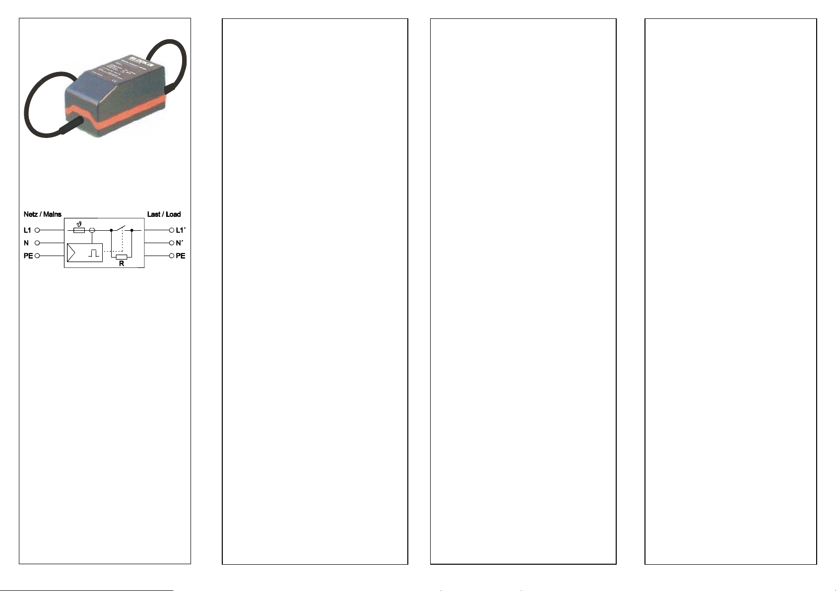
Abbildung / Figure
5
3
Abb. 1 / Fig. 1 ESG 3 ESG 4 ESG 5
Blockschaltbild / Block Diagram
Sicherheits- und Anwendungshinweise
Wir beglückwünschen Sie zum Erwerb dieses hochwertigen Produktes. In dem beschriebenen Anwendungsbereich wird es im bestimmungsgemäßen Betrieb lange seine Funktion erfüllen. Wie bei
jedem technischen Produkt kann jedoch die Gefahr von schweren
Personen- oder Sachschäden bei unsachgemäßem Einsatz, unzulässigem Entfernen von erforderlichen Abdeckungen sowie bei falscher Installation oder Bedienung bestehen. Folgen Sie dieser Gebrauchsanleitung und verfahren Sie nach den anerkannten Regeln
der Technik. Alle Arbeiten zur Installation, Inbetriebnahme und Betrieb sowie zur Instandhaltung sind von qualifiziertem Fachpersonal auszuführen (IEC 60364 / VDE 0105).
Verpackung
Bitte untersuchen Sie das Gerät sofort auf Transportschäden wie
Deformation, Bruch oder lose Teile. Beschädigungen bitte unverzüglich beim Transportunternehmen reklamieren; auch wenn die
Verpackung äußerlich nicht beschädigt ist.
Lagerung
zulässige Lagerungstemperatur -25°C...+85°C
zulässige Luftfeuchtigkeit 30%...80% relative Feuchte
Es ist keine Betauung zulässig.
bei Langzeitlagerung Gerät mit eingebauten Konden satoren: mindestens alle 2 Jahre
für 5 Minuten an Netzspannung
anlegen.
Installation und Inbetriebnahme
Das Gerät ist vor unzulässiger Beanspruchung zu schützen Die
Berührung elektrischer Bauelemente und Kontakte ist zu vermeiden. Die Produktbeschreibung und die technischen Hinweise in
unserem Hauptkatalog sowie die Aufschriften auf dem Gerät sind
zu beachten. Die Installation ist entsprechend den örtlichen Gegebenheiten, einschlägigen Vorschriften (z.B. VDE0100), nationalen
Unfallverhütungsvorschriften (z.B. UVV-VBG4 bzw. BGV A2) und
den anerkannten Regeln der Technik durchzuführen.
Wartung und Instandhaltung
Das Gerät bedarf in der Regel keiner besonderen Wartung, es ist
jedoch (entsprechend seiner Schutzart) vor aggressiven Chemikalien, Feuchte, Staub und Strahlung zu schützen. Die Instandsetzung ist nur im Rahmen der in dieser Gebrauchsanleitung aufgeführten Maßnahmen statthaft. Sollte es dennoch einen Ausfall geben, schicken Sie das Gerät bitte zur Reparatur an uns ein. Geben
Sie bitte an: Art des Fehlers, Begleitumstände (Einsatzbedingungen), eigene Vermutungen über die Fehlerursache, vorausgegangene ungewöhnliche Vorkommnisse, usw.
Entsorgung
Bitte beachten Sie die aktuellen Bestimmungen und entsorgen Sie
je nach Beschaffenheit, z.B. Elektronikschrott (Leiterplatten),
Kunststoff (Gehäuse), Kupfer, usw.
Änderungen
Unser Haus hat die Produktdokumentation mit großer Sorgfalt erstellt und geprüft. Es kann jedoch keine Gewährleistung bezüglich
der Fehlerfreiheit und Vollständigkeit übernommen werden. Eine
Übertragbarkeit der Angaben auf die jeweilige Anwendung ist zu
prüfen. Die technischen Daten beschreiben die Eigenschaften des
Produktes, ohne diese zuzusichern. Änderungen, die dem technischen Fortschritt dienen, sind vorbehalten.
Beschreibung und Einsatzgebiet
Beim Einschalten von bestimmten Verbrauchern kann es physikalisch bedingt zum Auslösen des vorgeschalteten Sicherungsautomaten oder des Motorschutzschalters kommen. Dieses Auslösen
wird durch den Einschaltstrombegrenzer verhindert. Bis zu einer
Gesamtstromaufnahme von max. 16A kann der Verbraucher über
den Einschaltstrombegrenzer eingeschaltet und versorgt werden.
Der Einschaltstrombegrenzer wird in die Verbraucherzuleitung eingefügt. Er hat einen Innenwiderstand (Begrenzungswiderstand)
von typ. 7,8Ω, der in Reihenschaltung zum Verbraucher liegt. Somit kann ein max. Einschaltstrom von 29,5A bei 230Vac fließen
(der tatsächliche max. Einschaltstrom ist aufgrund vorhandener
Netz- u. Verbraucherimpedanzen meist geringer). Im Normalfall
sind nach einigen Netzperioden die Einschaltstromspitzen abgeklungen und das eingebaute Leistungsrelais überbrückt den Innenwiderstand des Einschaltstrombegrenzers. Der Verbraucher ist
dann direkt mit der Netzspannung verbunden. Der Einschaltstrombegrenzer arbeitet hautsächlich stromgeführt und teilweise zeitgeführt, d.h. der Laststrom wird kontinuierlich überwacht. Unterhalb
einer Mindestlast von typ. 20W wird Leerlauf erkannt und der Begrenzungswiderstand wird dauerhaft in den Stromkreis geschaltet.
Bei größerer Leistung ist der Begrenzungswiderstand überbrückt;
in diesem Zustand können keine Einschaltströme begrenzt werden. Die Dauer der Einschaltstrombegrenzung beträgt max.
300ms; sie reduziert sich in Abhängigkeit von der Last auf min.
60ms. Im Einschaltmoment des Einschaltstrombegrenzers findet
eine feste Begrenzungszeit von ca. 150ms statt.
Normen
Das Gerät entspricht den gesetzlichen Anforderungen und Normen
zur CE-Konformität und trägt das CE-Zeichen.
Betriebshinweise
Die Kühlung des Gerätes darf nicht beeinträchtigt werden; eine ungehinderte Luftzufuhr ist sicherzustellen. Aufgrund der IP-Schutzart ist der Betrieb nur in trockenen Räumen zulässig.
Anschlußhinweise
Der Netzstecker des Verbrauchers wird über den Einschaltstrombegrenzer mit der Netzsteckdose verbunden. Für den sicheren Betrieb des Einschaltstrombegrenzers ist eine Bemessungsspannung
erforderlich, die beim Einschalten des Verbrauchers nicht unter
99Vac sinken darf. Größere Spannungseinbrüche können zur
Überlastung und somit zu irreparablen Schäden am Einschaltstrombegrenzer durch Auslösen der internen Temperatursicherung
führen!
Anschluß
Überprüfen Sie vor Anschluß des Einschaltstrombegrenzers die
zugehörige Betriebsspannung (siehe auch Geräteaufschrift).
Sicherung
Das Gerät ist intern mit einer nicht rückstellbaren Temperatursicherung ausgestattet. Löst diese Sicherung aus, liegt mit hoher
Wahrscheinlichkeit ein nicht geeignetes Stromversorgungsnetz vor
(siehe Anschlußhinweise).
Technische Daten
Nennspannung 110…230Vac
Spannungsbereich 99…253Vac
Nennfrequenz 50Hz...60Hz
Nennstrom ESG 3: bis zu 16A eff. *
ESG 4: bis zu 13A eff. *
ESG 5: bis zu 13A eff. *
* bei max. +40°C Umgebungstemperatur
Innenwiderstand ESG 3: 7,8Ω ±5% *
ESG 4: 7,8Ω ±5% *
ESG 5: 4,4Ω ±5% *
* im Einschaltmoment
Schaltzeit Überbrückung nach ca. 60ms...300ms
(3...15 Perioden bei 50Hz) je nach Last
Anschlüsse ESG 3: 2x 1,3m-Netzanschlußleitung
H05VV-F3G 1mm²
Stecker und Kupplung: DIN49440;1
ESG 4: 2x 1,3m-Netzanschlußleitung
H05VV-F3G 1mm²
Stecker und Kupplung: BS1363
ESG 5: 2x 1,3m-Netzanschlußleitung
SJT 3x16AWG (1,3mm²)
Stecker und Kupplung: NEMA5-15
Bauart gekapselt und vergossen
in einem Isolierstoffgehäuse
Schutzklasse I
Schutzart Gehäuse: IP65
Stecker/Kupplung (ESG 3): IP44
Stecker/Kupplung (ESG 4/5): IP20
Sicherheit ● integrierte, nicht auswechselbare
Temperatursicherung im Lastkreis
● Temperaturüberwachung überbrückt
Begrenzungswiderstand bei Überlast
● Vergußmasse nach UL 94 V-0
Gehäusemaße Länge: 121mm *
Breite: 66mm *
Höhe: 70mm *
* ohne die zwei Anschlußleitungen
Gewicht ca. 750g
mit den zwei Anschlußleitungen
2 3 4 5
 Loading...