

Block EB-MODBUS-RTU User manual [ml]
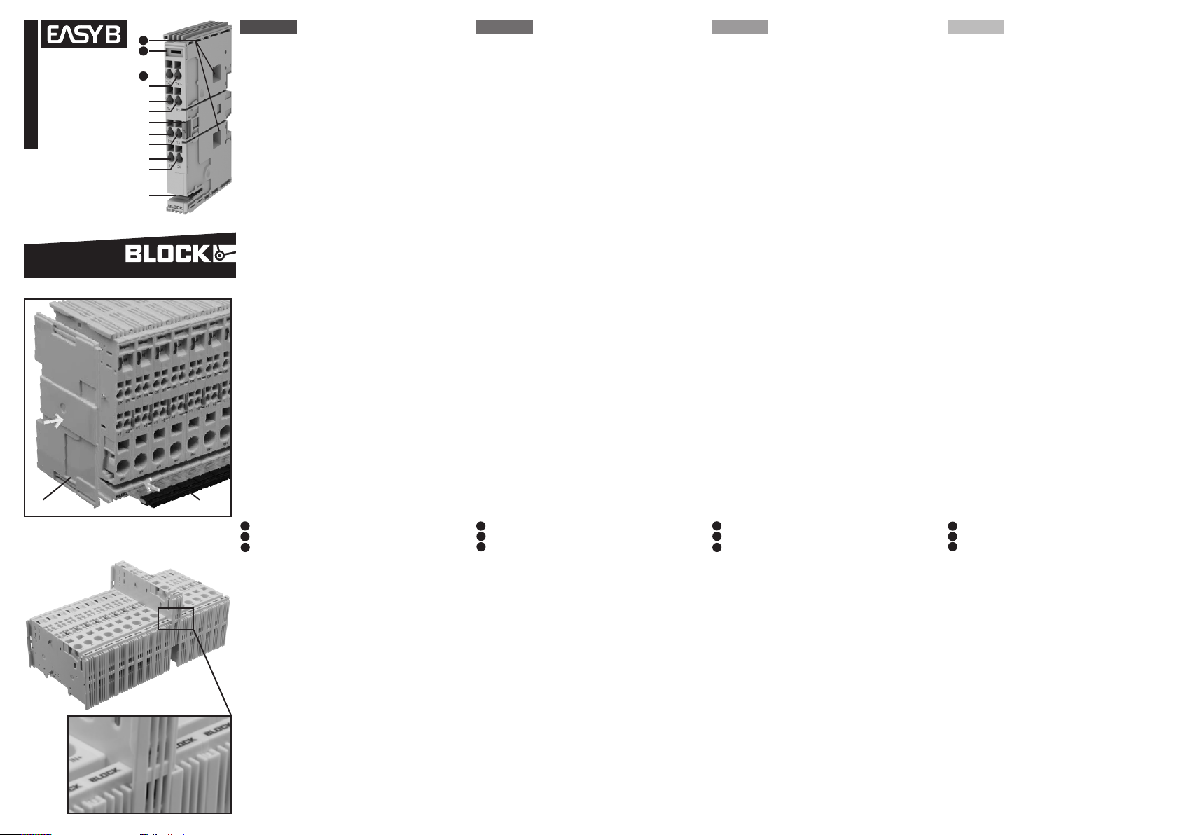
Fig. 1
12
EB-MODBUS-RTU
Koppelmodul
Coupling module
Module de couplage
Módulo de acoplamiento
11
10
9
8
7
6
español / français / english / deutsch
5
4
3
2
1
BLOCK Transformatoren-Elektronik GmbH
Max-Planck-Straße 36-46 . 27283 Verden, Germany
info@block.eu . block.eu
#005-0269 27•06•2016
block.eu
Fig. 2
1
EB-COV
1
EB-BAR
2
Fig. 3
deutsch
Sicherheitshinweise
T ACHTUNG:
Das Gerät ist nur für den Betrieb an Gleichspannungen bis max. 30V
geeignet. Der Anschluss an höhere Versorgungsspannungen kann zu
schweren Körperverletzungen bis hin zum Tod sowie zu erheblichen
Sachschäden führen.
T ACHTUNG:
Das Gerät darf nur durch fachkundiges und qualifiziertes Personal
installiert werden. Bei Funktionsstörungen oder Beschädigungen
schalten Sie sofort die Versorgungsspannung ab und senden das
Gerät zur Überprüfung ins Werk zurück. Das Gerät beinhaltet keine
Servicebauteile und ist für den Einbau in ein Gehäuse konzipiert.
T VORSICHT:
Verletzungsgefahr durch scharfkantige Messerkontakte! Da die
Messerkontakte sehr scharfkantig sind, besteht bei unvorsichtiger
Handhabung mit den Schutzschaltern Verletzungsgefahr.
block.eu
Funktionsbeschreibung:
Das Koppelmodul dient zur Kommunikation des elektronischen EasyBSchutzschaltersystems mit einer übergeordneten Steuerung (SPS,
PC). Weiterhin bietet das Modul einen Sammelreseteingang und zwei
potenzialfreie Sammelmeldekontakte.
Die elektronischen Geräteschutzschalter der Baureihe EasyB bieten
selektiven Schutz von 24V Verbrauchern und lassen sich modular
anreihen. Verschiedene Auslösestromstärken mit und ohne aktive
Strombegrenzung sind verfügbar.
Die vorliegende Betriebsanleitung ist eine Kurzanleitung. Ausführliche
Daten finden Sie im Downloadbereich des Produkts unter www.
block.eu.
Aufbau Fig. 1:
Aufnahme Querverbinder EB-BAR
1
Summenmeldesignal „24“ (I > 90%)
2
Summenmeldesignal „14“ (min. 1 Kanal ausgelöst oder ausgeschaltet)
3
Sammeleingang „13“
4
Reseteingang „RE“
5
Entriegelungslasche
6
Schnittstelle Rx+ (RS 422)
7
Schnittstelle Rx- (RS 422)
8
2
Schnittstelle TxD+ (RS 422, RS 485)
9
10
Schnittstelle TxD- (RS 422, RS 485)
11
Beschriftungsfeld für 5 mm und 6 mm Markiersysteme
12
DIP-Schalter zur Konfiguration der Schnittstelle
Montage Fig. 2, Fig. 3:
Montieren Sie das Gerät waagerecht auf der Normprofilschiene TH
35-15/7,5 (EN 60715). Das Gerät ist so zu montieren, dass die Lüftungsschlitze nach oben beziehungsweise nach unten gerichtet sind.
Halten Sie einen Mindestabstand von 30mm nach oben und unten ein.
Weitere Module werden seitlich eingeschoben. Für korrekte Funktion
ist das Koppelmodul immer als erstes Modul ganz links zu montieren.
Als Abdeckung des linken Moduls auf der linken Gehäuseseite ist die
Abdeckung EB-COV
Anschließen:
Dimensionieren Sie die Leitungen dem max. Eingangs-/Ausgangsstrom entsprechend. Die zulässigen Leitungsquerschnitte entnehmen
Sie Tabelle 1. Schließen Sie die +24V Versorgungsspannung an die
Einspeiseklemme In+ eines benachbarten Schutzschalters an. Die
+24V Versorgungsspannung wird durch den Querverbinder EB-BAR
2 über alle Module gebrückt. Alle weiteren Signalverbindungen
sind durch das Anreihen automatisch gebrückt. Bei Strömen >40
A sind mehrere Einspeiseklemmen zu verwenden. Wählen Sie die
Einspeiseklemmen so, dass der Strom im Querverbinder 80A nicht
überschreitet.
Demontage:
Entfernen Sie den Querverbinder EB-BAR und alle angeschlossenen
Leitungen vom zu demontierenden Modul. Ziehen Sie es an der
Entriegelungslasche aus dem Verbund heraus.
1 erforderlich.
english
Safety instructions
T CAUTION:
The device is only suitable for operation at DC voltages up to a
maximum of 30 V. Connection to higher supply voltages may result in
severe physical injury or even death, as well as significant material
damage.
T CAUTION:
The device may only be installed by qualified personnel with the
relevant expertise. In the event of malfunction or damage, shut down
the supply voltage immediately and return the device to the factory to
be checked. The device does not contain any serviceable parts and is
designed to be installed inside its housing.
T CAUTION:
Risk of injury due to sharp-edged blade contacts! The blade contacts
have very sharp edges, so there is a risk of injury if circuit breakers
are not handled with care.
Functional description:
The coupling module serves for communication of the electronic
EasyB circuit breaker system with a higher level controller (SPC, PC).
Furthermore the module offers a summation reset input and two
isolated group signal contacts.
The electronic circuit breakers in the EasyB range offer selective
protection for 24 V loads and can be arranged in rows on a modular
basis. Various tripping currents are avaliable,with or without active
current limiting.
These operating instructions are only intended as a brief guide. You
can find more detailed information in the download area for the
product at www.block.eu.
Structure Fig. 1:
Entry point, EB-BAR cross-connector
1
Group signal “24” (I > 90%)
2
Group signal “14” (min. 1 channel tripped or switched off)
3
Summation input “13”
4
Reset input “RE”
5
Release tab
6
Interface Rx+ (RS 422)
7
Interface Rx- (RS 422)
8
Interface TxD+ (RS 422, RS 485)
9
10
Interface TxD- (RS 422, RS 485)
11
Labelling field for 5 mm and 6 mm marking systems
12
DIP switches for interface configuration
Mounting Fig. 2, Fig. 3:
Mount the device horizontally on the TH 35-15/7.5 standard profile
rail (EN 60715). When mounting the device, make sure the ventilation
slits are facing either upwards or downwards. You should ensure a
minimum clearance distance of 30 mm above and below. Additional
modules are inserted at the side. For correct function the coupling
module must be installed as first module on the left hand side. The
module on the left to the left side of the housing needs to be covered
with the EB-COV cover
Connection:
Dimension the cables on the basis of the max. input/output current.
Please see Table 1 for the permissible cable cross-sections. Connect
the +24 V supply voltage at the In+ power terminal on a neighbouring
circuit breaker. The EB-BAR cross-connector 2 is used to jumper
the +24 V supply voltage across all the modules. All the other signal
connections are automatically jumpered due to things being in a
row. Several power terminals need to be used for currents > 40 A.
When choosing power terminals, make sure the current in the crossconnector does not exceed 80 A.
Demounting:
Remove the EB-BAR cross-connector and all the connected cables
from the module to be demounted. To remove it from the assembly,
pull on the release tab.
1.
français
Consignes de sécurité
T ATTENTION:
L‘appareil doit être soumis exclusivement à des de tensions continues
de 30 V max. Un raccordement à des tensions d‘alimentation
supérieures peut entraîner des blessures graves, voire mortelles ainsi
que d‘importants dommages matériels.
T ATTENTION:
L‘appareil ne doit être installé que par du personnel compétent et
qualifié. En cas de dysfonctionnement ou de dommage matériel,
coupez immédiatement l‘alimentation en tension et renvoyez l‘appareil
à l‘usine pour vérification. L‘appareil ne contient aucune pièce
d‘entretien et est conçu pour être intégré dans un boîtier.
T PRUDENCE:
Risque de blessure lié aux arêtes vives des contacts à couteau ! Les
arêtes des contacts à couteau étant très tranchantes, il existe un
risque de blessure en cas de maniement imprudent des disjoncteurs.
Description du fonctionnement:
Le module de couplage sert à la communication du système disjoncteur
EasyB électronique avec un dispositif de commande principal (API, PC).
De plus, le module dispose d‘une entrée de réinitialisation collective et
de deux contacts de signalisation collective libres de potentiel.
Les disjoncteurs électroniques de la gamme EasyB offrent
une protection sélective des consommateurs 24 V et peuvent
être juxtaposés de façon modulaire. Différentes intensités de
déclenchement avec ou sans limitation active du courant sont
disponibles.
Cette notice d‘utilisation est une version condensée. Vous trouverez
des données détaillées dans la rubrique Téléchargement du produit
sur le site www.block.eu.
Montage Fig. 1 :
Consommation connecteur transversal EB-BAR
1
Signal d‘état collectif „24“ (I > 90 %)
2
Signal d‘état collectif „14“ (min. 1 canal déclenché ou désactivé)
3
Entrée collective „13“
4
Entrée de réinitialisation „RE“
5
Bride de déverrouillage
6
Interface Rx+ (RS 422)
7
Interface Rx- (RS 422)
8
Interface TxD+ (RS 422, RS 485)
9
10
Interface TxD- (RS 422, RS 485)
11
Champ d‘inscription pour systèmes de marquage 5 mm
12
Commutateur DIP pour configuration de l‘interface
Montage Fig. 2, Fig. 3 :
Montez l‘appareil à l‘horizontale sur le rail profilé normalisé TH 3515/7,5 (EN 60715). L‘appareil doit être monté de manière à ce que
les grilles d‘aération soient orientées vers le haut ou vers le bas.
Respectez un écart minimum de 30 mm en haut et en bas. D‘autres
modules sont insérés latéralement. Pour un fonctionnement correct,
le module de couplage doit toujours être monté complètement à
gauche en tant que premier module. Pour le module gauche sur le
côté gauche du boîtier, la couverture EB-COV
Raccordement :
Dimensionnez les câbles en fonction du courant d‘entrée/de sortie
max. Les sections de câbles admissibles sont répertoriées dans
le tableau 1. Raccordez la tension d’alimentation +24 V à la borne
d’alimentation In+ d’un disjoncteur adjacent. La tension d‘alimentation
+24 V est pontée sur tous les modules via le connecteur
transversal EB-BAR 2. Toutes les autres liaisons de signaux
sont automatiquement pontées du fait de la juxtaposition. Pour les
courants >40 A, il convient d‘utiliser plusieurs bornes d‘alimentation.
Sélectionnez les bornes d‘alimentation de manière à ne pas dépasser
le courant du connecteur transversal 80 A.
Démontage :
Retirez le connecteur transversal EB-BAR et tous les câbles du
module à démonter. Tirez il au niveau de la bride de déverrouillage
pour l‘extraire de l‘ensemble.
1 est requise.
español
Indicaciones de seguridad
T ATENCIÓN:
Este aparato solo está indicado para el funcionamiento con
corrientes continuas de 30 V máx. La conexión a tensiones de
suministro más altas puede resultar en lesiones físicas graves
e incluso la muerte, así como en daños materiales significativos.
T ATENCIÓN:
El aparato solo debe ser instalado por personal profesional
calificado. En caso de fallas de funcionamiento o daños,
desconecte la tensión y envíe el aparato a la fábrica para su
revisión. El aparato no contiene piezas de mantenimiento y está
diseñado para ser instalado en una carcasa.
T PRECAUCIÓN:
Peligro de lesiones por contactos de cuchilla filosos. Dado que
los contactos de cuchilla son muy filosos, existe un peligro de
lesión si se manipulan los disyuntores sin cuidado.
Descripción del funcionamiento:
El módulo de acoplamiento sirve para la comunicación del sistema
interruptor de protección EasyB con un control de orden superior
(PLC, PC). Además, el módulo ofrece una entrada de reseteo
colectivo y dos contactos de notificación en bloque sin potencial.
Los disyuntores electrónicos de la serie EasyB ofrecen una
protección selectiva para consumidores de 24 V y se pueden
conectar en fi la, modularmente. Están disponibles con distintas
corrientes de desconexión con y sin limitación activa de la
corriente.
La presente guía de instruccioneses una guía rápida. Podrá
encontrar más información en la zona de descargas del producto
en www.block.eu.
Construcción fig. 1
Alojamiento conector transversal EB-BAR
1
Señal de notificación total “24” (I > 90 %)
2
Señal de notificación total “14” (mín. 1 canal accionado o desconectado)
3
Entrada de arranque colectivo “13”
4
Entrada de reseteo “RE”
5
Lengüeta de desbloqueo
6
Interfaz Rx+ (RS 422)
7
Interfaz Rx- (RS 422)
8
Interfaz TxD+ (RS 422, RS 485)
9
10
Interfaz TxD- (RS 422, RS 485)
11
Campo de rotulado para sistemas de marcado de 5 mm
12
Interruptor DIP para configuración de la interfaz
Montaje fig. 2, fig. 3:
Instale el aparato horizontalmente sobre la guía de perfil estándar
TH 35-15/7,5 (EN 60715). El aparato debe ser instalado de
manera que las ranuras de ventilación miren hacia arriba o hacia
abajo. Respete una distancia mínima de 30 mm hacia arriba y
hacia abajo. Los módulos adicionales se insertan lateralmente.
Para un correcto funcionamiento, el módulo de acoplamiento se
debe montar primero y bien a la izquierda. La cubierta EB-COV
1 es necesaria como cubierta del módulo izquierdo del lado
izquierdo de la carcasa.
Conectar:
Dimensione los cables de acuerdo a las corrientes máximas
de entrada/salida. En la tabla 1 puede consultar las secciones
transversales de cables admitidas. Conecte la tensión de
alimentación de +24V a la terminal de alimentación In+ de un
interruptor de protección contiguo. La tensión de suministro de
+24 V se conecta en puente a lo largo de todos los módulos por
medio del conector transversal EB-BAR 2. Las conexiones de
señal restantes se puentean automáticamente por la instalación en
fila. En caso de corriente >40 A se deben emplear varios bornes
de alimentación. Elija los bornes de alimentación de manera que la
corriente del conector transversal no supere 80 A.
Desmontaje:
Desconecte el conector transversal EB-BAR y todos los cables
conectados al módulo que desea desinstalar. Retirese del
conjunto usando la palanca de desbloqueo.
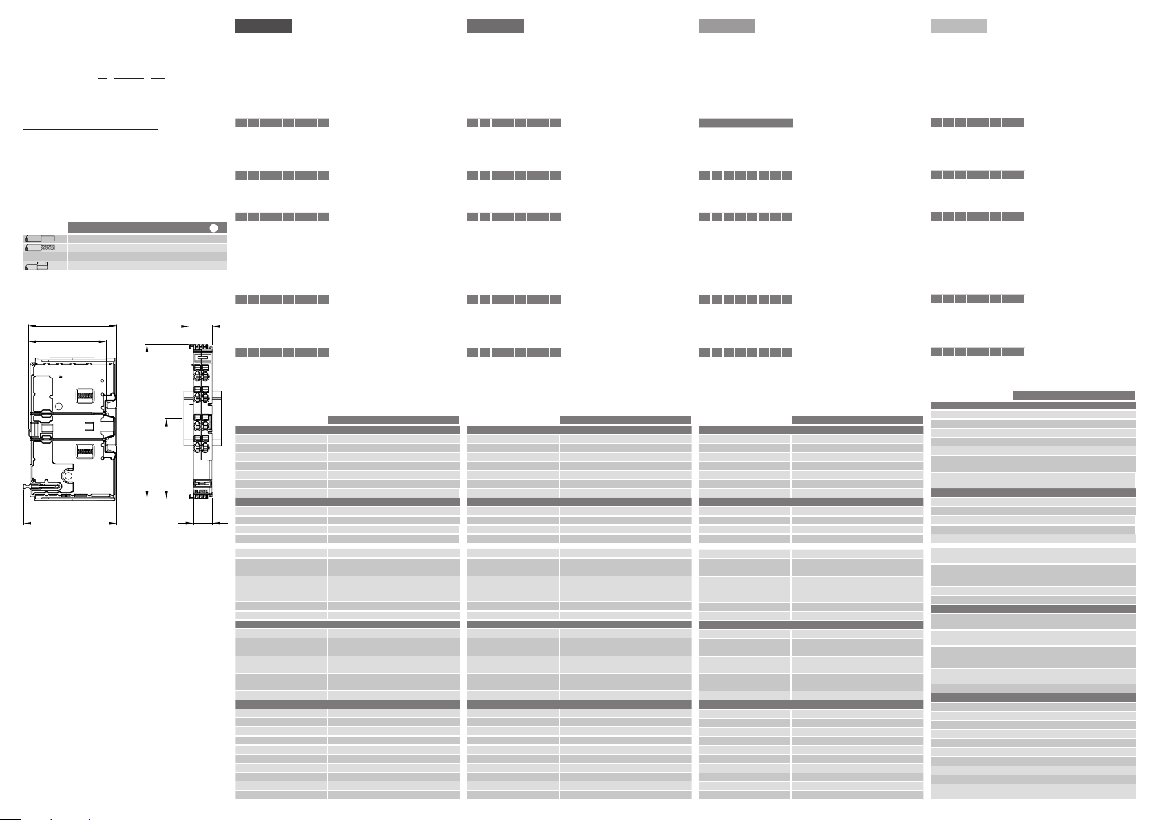
Artikelnummerbeschreibung / Part number
designation /Description référence / Descripción
de número de artículo:
Fig. 4
Series Name
Type
MODBUS: Modbus coupling module
Variant
RTU: binary RTU operating mode (remote terminal unit)
EB - MODBUS - RTU
Klemmdaten / Terminal data / Caractéristiques
des bornes / Datos de los bornes:
Table 1
AWG 28 ... 14
2 + 3
+
+
+
4
5
0,08 ... 2,5 mm
0,08 ... 2,5 mm
8 mm
+
7
8 + 9 + 1
2
2
10
Maßzeichnung / Dimensions / Dimensions /
Dibujo acotado:
61.2
53.7
64.5
14.8
99.3
51.7
12
Prüfzeichen / Markings / Approbation / Marcas
de verificación:
J
UL in Vorbereitung / UL in preparation / UL en préparation /
UL en preparación
GL in Vorbereitung / GL in preparation / GL en préparation /
GL en preparación
BLOCK Transformatoren-Elektronik GmbH
Max-Planck-Straße 36-46 . 27283 Verden, Germany
info@block.eu . block.eu
Technische Änderungen vorbehalten.
Subject to change.
Sous réserve de mofications techniques.
Sujeto a moficaciones.
deutsch english français español
Konfiguration Configuration
Die Konfigurationsparameter der Schnittstelle lassen sich an den zwei seitlichen
DIP-Schaltern einstellen (siehe Maßzeichnung). Eine Schalterstellung nach oben
bedeutet eine logische “1”, während Schalterstellung nach unten für eine logische
“0” steht.
DIP-Schalter oben:
Terminierung (Abschlusswiderstände) Termination (load resistors)
1 2 3 4 5 6 7 8
0 0 0 0
1 1 0 0 RS 485 (2-Draht)
1 1 1 1 RS 422 (4-Draht)
Empfangskonfiguration (Rx) Receiving configuration (Rx)
1 2 3 4 5 6 7 8
End of frame time End of frame time
1 2 3 4 5 6 7 8
DIP-Schalter unten: DIP-Schalter unten:
MODBUS-Adresse MODBUS address
1 2 3 4 5 6 7 8
0 0 0 0 1
x x x x x Adresse X
1 1 1 1 1 Adresse 31
Baudrate Baud rate
1 2 3 4 5 6 7 8
1 0
0 1 4-Draht
Technische Daten: Technical data:
Eingangsdaten
Eingangsnennspannung DC 24 V
Eingangsspannungsbereich 18 - 30 Vdc
Ein- und Ausschaltschwelle 17,5 V ± 0,7 V (ein) / 16,7 V ± 0,7 V (aus)
Rückspeisefestigkeit 35 V
Modulinitialisierungszeit 4,68 ms
Ruhestrom / max. Verlustleistung 26 mA / 0,85 W
Anschlüsse Eingang seitl. Messer-/Federkontakt (-) / Sammelschiene (+)
Schnittstelle
MODBUS Schnittstelle RTU-Modus, 8 bit, keine Parität, 2 Stop Bit
Übertragungsart (einstellbar) RS 485 (TxD+, TxD-) RS 422 (TxD+, TxD-, Rx, R-)
Max. Bus-Teilnehmer 31
Adressierung (einstellbar) 1 ... 31
Baudrate (einstellbar) 4800 Bd, 9600 Bd (Standard), 19200 Bd
Terminierung RS 485
(zuschaltbar)
Terminierung RS 422
(zuschaltbar)
End of Frame Time (einstellbar) 1 ms, 10 ms, 500 ms, 3x Frame (Standard)
Anschlüsse Schnittstelle Charge Clamp, max. 2,5 mm
Signalisierung
Potentialfreier Sammeleingang „13“ Solid-State Relais, max. 58 Vdc / 40 Vac / 100 mA
Potentialfreier Ausgang „14“
(konfigurierbar)
Potentialfreier Ausgang „24“ Solid-State Relais, max. 58 Vdc / 40 Vac / 100 mA
Reseteingang „RE“ DC 24 V (Reset)
Anschlüsse Signalisierung Charge Clamp, max. 2,5 mm
Allgemeine Daten
Umgebungstemperatur -25 °C ... +70 °C
Lagertemperatur -25 °C ... +85 °C
Schutzart IP 20
Verschmutzungsgrad 2
Luftfeuchtigkeit 5 ... 96 %, keine Kondensation
Klimaklasse 3K3
Schutzklasse III
Überspannungskategorie I
Gewicht 40 g
Maße (B x H x T) inkl. TH35 15 x 99 x 60 mm
aus
2-Draht
3,5 Byte
0 0
0 1 10 ms
1 0 50 ms
1 1 500 ms
Adresse 1
9600 Bd (Standard)
0 0
0 1 4800 Bd
1 0 19200 Bd
EB-MODBUS-RTU
390 Ω (TxD+ / +5 V; TxD- / GND)
150 Ω (TxD+ / TxD-)
390 Ω (TxD+ / +5 V; TxD- / GND)
390 Ω (Rx+ / +5 V; Rx- / GND)
150 Ω (TxD+ / TxD-; Rx+ / Rx-)
Solid-State Relais, max. 58 Vdc / 40 Vac / 100 mA
offen: min. ein Kanal ausgelöst, geschlossen: OK
offen: min. ein Kanal >90 %, geschlossen: alle K. <90 %
Level high: 11 V ... 30 V, Level low: 0 V ... 5 V
2
2
The interface configuration parameters are adjustable on the two lateral DIP
switches (see dimensional drawing). Switch position up means a logical “1”,
whereas switch position down stands for a logical “0”.
Upper DIP switch:
1 2 3 4 5 6 7 8
0 0 0 0
1 1 0 0 RS 485 (2-wire)
1 1 1 1 RS 422 (4-wire)
1 2 3 4 5 6 7 8
1 2 3 4 5 6 7 8
1 2 3 4 5 6 7 8
0 0 0 0 1
x x x x x address X
1 1 1 1 1 address 31
1 2 3 4 5 6 7 8
Input data
Rated input voltage DC 24 V
Input voltage range 18 - 30 Vdc
Turn-on /-off treshold 17.5 V ± 0.7 V (on) / 16.7 V ± 0.7 V (off)
Resistance to reverse feed (max.) 35 V
Module initialisation time 4,68 ms
Quiescent current / Max. power loss 26 mA / 0.85 W
Terminals input lateral blade/spring-contact (-) / cross-connector (+)
Interface
MODBUS interface RTU mode, 8 bit, no parity, 2 stop bit
Transmission mode (adjustable) RS 485 (TxD+, TxD-) RS 422 (TxD+, TxD-, Rx, R-)
Max. bus members 31
Addressing (adjustable) 1 ... 31
Baud rate (adjustable) 4800 Bd, 9600 Bd (Standard), 19200 Bd
Termination RS 485
(switchable)
Termination RS 422
(switchable)
End of Frame Time (adustable) 1 ms, 10 ms, 500 ms, 3x Frame (standard)
Terminals interface Charge Clamp, max. 2.5 mm
Signaling
Potential-free summation input “13” Solid-state relay, max. 58 Vdc / 40 Vac / 100 mA
Potential-free group output “14”
(adjustable
Potential-free group output “24” Solid-State Relais, max. 58 Vdc / 40 Vac / 100 mA
Reset input “RE” DC 24 V (Reset)
Terminals signaling Charge Clamp, max. 2.5 mm
General data
Operational ambient temperature -25 °C ... +70 °C
Storage ambient temperature -25 °C ... +85 °C
Degree of protection IP 20
Degree of contermination 2
Air humidity 5 ... 96 %, no condensation
Climatic class 3K3
Protection class III
Overvoltage category I
Weight 40 g
Dimensions (W x H x D) incl. TH35 15 x 99 x 60 mm
1 0
0 1 4-wire
off
2-wire
3.5 Byte (standard)
0 0
0 1 10 ms
1 0 50 ms
1 1 500 ms
address 1
9600 Bd (standard)
0 0
0 1 4800 Bd
1 0 19200 Bd
EB-MODBUS-RTU
390 Ω (TxD+ / +5 V; TxD- / GND)
150 Ω (TxD+ / TxD-)
390 Ω (TxD+ / +5 V; TxD- / GND)
390 Ω (Rx+ / +5 V; Rx- / GND)
150 Ω (TxD+ / TxD-; Rx+ / Rx-)
Solid-state relay, max. 58 Vdc / 40 Vac / 100 mA
open: min. one channel tripped, closed: OK
open: min. one channel >90 %, closed: all c. <90 %
Level high: 11 V ... 30 V, Level low: 0 V ... 5 V
Configuration
Les paramètres de configuration de l’interface peuvent être réglés à l’aide des
deux commutateurs DIP latéraux (voir dessin coté). Un commutateur positionné
en haut correspond à un “1” logique, alors qu’un commutateur positionné en bas
correspond à un “0” logique.
Commutateur DIP en haut:
Terminaison (résistances de terminaison)
1 2 3 4 5 6 7 8
0 0 0 0
1 1 0 0 RS 485 (2 fils)
1 1 1 1 RS 422 (4 fils)
Configuration de la réception (Rx)
1 2 3 4 5 6 7 8
Fin du cadre temporel
1 2 3 4 5 6 7 8
Commutateur DIP en bas:
Adresse MODBUS
1 2 3 4 5 6 7 8
0 0 0 0 1
x x x x x Adresse X
1 1 1 1 1 Adresse 31
Débit en bauds
1 2 3 4 5 6 7 8
1 0
0 1 4 fils
Caractéristiques techniques:
Données d'entrée
Tension nominale d'entrée 24 V CC
Plage de tension d'entrée 18 - 30 V CC
Seuil d'activation et de désactivation 17,5 V ± 0,7 V (activation) / 16,7 V ± 0,7 V (désactivation)
Résistance à l'alimentation de retour 35 V
Durée d'initialisation du module 4,68 ms
Courant de repos / puissance dissipée max.
Connexions entrée Contact à couteau/à ressort latéral (-) / Barre omnibus (+)
Interface
Interface MODBUS RTU-Modus, 8 bits, pas de parité, 2 bits d'arrêt
Mode de transmission (réglable) RS 485 (TxD+, TxD-) RS 422 (TxD+, TxD-, Rx, R-)
Périphériques de bus max. 31
Adressage (réglable)
Débit en bauds (réglable) 4800 Bd, 9600 Bd (standard), 19200 Bd
Terminaison RS 485
(commutable)
Terminaison RS 422
(commutable)
2
2
Fin du cadre temporel (réglable) 1 ms, 10 ms, 500 ms, 3x cadre (standard)
Connexions interface Dispositif de serrage de charge, max. 2,5 mm
Signalisation
Entrée collective sans potentiel "13" Relais à semi-conducteurs, max. 58 V CC / 40 V CA / 100 mA
Sortie sans potentiel "14"
(configurable)
Sortie sans potentiel "24" Relais à semi-conducteurs, max. 58 V CC / 40 V CA / 100 mA
Entrée de réinitialisation "RE" 24 V CC (réinitialisation)
Connexions de signalisation Dispositif de serrage de charge, max. 2,5 mm
Données générales
Température ambiante -25 °C ... +70 ℃
Température de stockage -25 °C ... +85 ℃
Type de protection IP 20
Degré d'encrassement 2
Humidité de l'air 5 ... 96 %, sans condensation
Classe climatique 3K3
Classe de protection III
Catégorie de surtension I
Poids 40 g
Dimensions (L x H x P) incl. TH35 15 x 99 x 60 mm
désactivé
2 fils
3,5 octets
0 0
0 1 10 ms
1 0 50 ms
1 1 500 ms
Adresse 1
9600 Bd (standard)
0 0
0 1 4800 Bd
1 0 19200 Bd
EB-MODBUS-RTU
26 mA / 0,85 W
1 ... 31
390 Ω (TxD+ / +5 V; TxD- / GND)
150 Ω (TxD+ / TxD-)
390 Ω (TxD+ / +5 V; TxD- / GND)
390 Ω (Rx+ / +5 V; Rx- / GND)
150 Ω (TxD+ / TxD-; Rx+ / Rx-)
Relais à semi-conducteurs, max. 58 V CC / 40 V CA / 100 mA
ouvert : min. un canal déclenché, fermé : OK
ouvert : min. un canal >90 %, fermé : tous les canaux <90 %
Niveau haut : 11 V ... 30 V, Niveau bas : 0 V ... 5 V
Configuración
Los parámetros de configuración de la interfaz se pueden ajustar de
los dos interruptores DIP laterales (véase el esquema dimensional). La
posición del interruptor hacia arriba significa un “1” lógico, mientras que la
posición del interruptor hacia abajo significa un “0” lógico.
Interruptor DIP arriba:
Terminación (resistencias terminales)
1 2 3 4 5 6 7 8
0 0 0 0
1 1 0 0 RS 485 (2 hilos)
1 1 1 1 RS 422 (4 hilos)
Configuración de recepción (Rx)
1 2 3 4 5 6 7 8
End of frame time
1 2 3 4 5 6 7 8
Interruptor DIP abajo:
Dirección de MODBUS
1 2 3 4 5 6 7 8
0 0 0 0 1
x x x x x Dirección X
1 1 1 1 1 Dirección 31
Tasa de baudios
1 2 3 4 5 6 7 8
Datos técnicos:
Datos de entrada
Tensión nominal de entrada CC 24 V
Rango de tensión de entrada 18 - 30 V CC
Umbral de conexión y desconexión 17,5 V ± 0,7 V (Con.) / 16,7 V ± 0,7 V (Desc.)
Resistencia al voltaje de retorno 35 V
Tiempo de inicialización del módulo 4,68 ms
Corriente de polarización/
máx. potencia disipada
Conexiones entrada Contacto de clavijas/elástico lat. (-) / barra
Interfaz
Interfaz MODBUS Modbus RTU-, 8 bit, sin paridad, 2 bits de parada
Clase de transferencia (ajustable) RS 485 (TxD+, TxD-) RS 422 (TxD+, TxD-, Rx, R-)
Unidades de bus máx. 31
Direccionamiento (ajustable) 1 ... 31
Tasa de baudios (ajustable) 4800 Bd, 9600 Bd (estándar), 19200 Bd
Terminación RS 485
(conectable)
Terminación RS 422
(conectable)
End of Frame Time (ajustable) 1 ms, 10 ms, 500 ms, 3x Frame (estándar)
Conexiones interfaz Charge Clamp, máx. 2,5 mm
Señalización
2
Entrada de arranque colectivo sin
potencial “13”
Salida sin potencial “14”
(configurable)
Salida sin potencial “24”
Entrada de reseteo “RE” DC 24 V (Reset)
Conexiones señalización Charge Clamp, máx. 2,5 mm
2
Datos generales
Temperatura ambiente -25 °C +70 °C
Temperatura de almacenamiento -25 °C +85 °C
Tipo de protección IP 20
Grado de suciedad 2
Humedad del aire 5 ... 96 %, sin condensación
Clase de clima 3K3
Clase de protección III
Categoría de sobretensión I
Peso 40 g
Medidas (ancho x alto x profundidad)
incl. TH35
desconectado
1 0
0 1 4 hilos
2 hilos
3,5 Byte
0 0
0 1 10 ms
1 0 50 ms
1 1 500 ms
Dirección 1
9600 Bd (estándar)
0 0
0 1 4800 Bd
1 0 19200 Bd
390 Ω (TxD+ / +5 V; TxD- / GND)
390 Ω (TxD+ / +5 V; TxD- / GND)
390 Ω (Rx+ / +5 V; Rx- / GND)
150 Ω (TxD+ / TxD-; Rx+ / Rx-)
Relé de estado sólido, máx. 58 VCC /
Relé de estado sólido, máx. 58 VCC / 40 VCA / 100 mA
abierto: mín. un canal accionado, cerrado: OK
Relé de estado sólido, máx. 58 VCC / 40 VCA / 100 mA
abierto: mín. un canal > 90 %, cerrado: todos los
Level high: 11 V ... 30 V, Level low: 0 V ... 5 V
EB-MODBUS-RTU
26 mA / 0,85 W
colectora (+)
150 Ω (TxD+ / TxD-)
2
40 VCA / 100 mA
canales <90 %
2
15 x 99 x 60 mm
 Loading...