

Page 1
SUITABLE FOR OUTDOOR USE
Blizzard Lighting, LLC
www.blizzardlighting.com
Waukesha, WI USA
Copyright (c) 2018
Page 2

TABLE OF CONTENTS
Tournado™ WiMAX Quadra 1
1. Getting Started 3
What’s In The Box? 3
Getting It Out Of The Box 3
Powering Up! 3
Getting A Hold Of Us 3
Safety Instructions (Don’t run with scissors!) 4
2. Meet The Tournado™ WiMAX Quadra 5
Main Features 5
DMX Quick Reference 5
The Tournado™ WiMAX Quadra Pin-up Picture 6
3. Setup 7
Fuse Replacement 7
Data/DMX Cables 7
Using The Built-in W-DMX™ 7
3-Pin??? 5-Pin??? Huh? 8
Take It To The Next Level: Setting up DMX Control 8
Fixture Linking (Master/Slave Mode) 9
Mounting/Rigging 9
4. Operating Adjustments 10
Navigating The Control Panel 10
Control Panel Menu Structure 11
DMX Mode 12
Set the Starting DMX Address 12
Setting the DMX Channel Mode 12
Slave Mode 12
Dimming Mode Settings 12
Custom Programs 13
Auto Mode, and Auto Speed 13
Color Calibration Settings 14
Custom Static Colors & Preset Colors 14
Fixture Reset Functions 15
Data Sync Feature 15
Fixture Information 15
DMX In-Depth Reference 17
Troubleshooting 17
5. Appendix 18
A Quick DMX Lesson 18
Keeping Your Tournado™ WiMAX Quadra As Good As New 19
Returns (Gasp!) 19
Shipping Issues 19
Tech Specs 20
Dimensional Drawings 21
Tournado™ WiMAX Quadra Manual Rev. A Copyright 2018 Blizzard Lighting, LLC
Page 2
Page 3

1. GETTING STARTED
What’s In The Box?
• 1 x Tournado™ WiMAX Quadra LED PAR xture
• 1 x IP Rated AC power cord
• 1 x DMX signal cable
• This lovely user manual
Getting It Out Of The Box
Congratulations! You’re now the proud owner of one tough, slightly pumpkin shaped PAR
xture! And now that you’ve got your TOURnado™ (or hopefully, TOURnados!), you should
carefully unpack the box and check the contents to ensure that all parts are present and
in good condition. If anything looks as if it has been damaged in transit, notify the shipper
immediately and keep the packing material for inspection. Again, please save the carton
and all packing materials. If a xture must be returned to the factory, it is important that
the xture be returned in the original factory box and packing.
Powering Up!
All xtures must be powered directly o a switched circuit and cannot be run o a
rheostat (variable resistor) or dimmer circuit, even if the rheostat or dimmer
channel is used solely for a 0% to 100% switch.
AC Voltage Switch - Not all xtures have a voltage select switch, so please verify that the
xture you receive is suitable for your local power supply. See the label on the xture or
refer to the xture’s specications chart for more information. A xture’s listed current
rating is its average current draw under normal conditions. Check the xture or device
carefully to make sure that if a voltage selection switch exists that it is set to the correct
line voltage you will use.
Warning! Verify that the voltage select switch on your unit matches the line
voltage applied. Damage to your xture may result if the line voltage applied does
not match the voltage indicated on the voltage selector switch. All xtures must
be connected to circuits with a suitable Ground (Earthing).
Getting A Hold Of Us
If something happens goes wrong, please visit www.blizzardlighting.com/
support and open a support ticket. We’ll be happy to help, honest.
Disclaimer: The information and specications contained in this document are subject
to change without notice. Blizzard Lighting™ assumes no responsibility or liability for any
errors or omissions that may appear in this user manual. Blizzard Lighting™ reserves the
right to update the existing document or to create a new document to correct any errors
or omissions at any time. You can download the latest version of this document from www.
blizzardlighting.com.
Author: Date: Last Edited: Date:
J. Thomas 6/27/2018 J. Thomas 7/9/2018
Tournado™ WiMAX Quadra Manual Rev. A Copyright 2018 Blizzard Lighting, LLC
Page 3
Page 4
SAFETY INSTRUCTIONS
Please read these instructions carefully. They include
important information about the installation, usage and
• Please keep this User Guide for future use. If you sell the unit to someone
else, be sure that they also receive this User Guide.
• ALWAYS make sure that you are connecting to the proper voltage, and that
the line voltage you are connecting to is not higher than that stated on the de-
cal or rear panel of the xture.
• Make sure there are no ammable materials close to the unit while operating.
• The unit must be installed in a location with adequate ventilation, at least
20in (50cm) from adjacent surfaces. Be sure that no ventilation slots are
blocked.
• ALWAYS disconnect from the power source before servicing or replacing fuse
and be sure to replace with same fuse size and type.
• ALWAYS secure xture using a safety chain. NEVER carry the xture by its
head. Use its carrying handles.
maintenance of this product.
• DO NOT operate at ambient temperatures higher than 104°F (40°C).
• In the event of a serious operating problem, stop using the unit immediately.
NEVER try to repair the unit by yourself. Repairs carried out by unskilled people
can lead to damage or malfunction. Please contact the nearest authorized technical assistance center. Always use the same type spare parts.
• NEVER connect the device to a dimmer pack.
• Make sure the power cord is never crimped or damaged.
• Never disconnect the power cord by pulling or tugging on the cord.
• Avoid direct eye exposure to the light source while it is on.
Caution! There are no user serviceable parts inside the unit. Do not
open the housing or attempt any repairs yourself. In the unlikely event
your unit may require service, please open a support ticket at www.
blizzardlighting.com/support.
Tournado™ WiMAX Quadra Manual Rev. A Copyright 2018 Blizzard Lighting, LLC
Page 4
Page 5
2. MEET THE TOURNADO™ WIMAX QUADRA
MAIN FEATURES
• Color mixing via 19x 15W RGBW 4-in-1 LEDs
• IP65 rated outdoor LED xture
• OLED control menu with 4x touch sensitive buttons
• 25-degree beam angle
• Built-in wireless W-DMX™ receiver
• Built-in color & chase macros via DMX
• Built-in automated programs via master/slave
• Color mixing ability in standalone mode
• 4/6/10-channel DMX proles w/32-bit dimming
• Convection cooled cast aluminum housing
• Dual mounting brackets for positioning exibility
• Flicker-free constant-current LED driver
• IP rated locking power and 3-pin DMX connections
DMX Quick Reference (4-Channel Mode)
Channel What is does...
1 Red Intensity (0 <--> 100%)
2 Green Intensity (0 <--> 100%)
3 Blue Intensity (0 <--> 100%)
4 White Intensity (0 <--> 100%)
DMX Quick Reference (6-Channel Mode)
Channel What is does...
1 Master Dimmer (0 <--> 100%)
2 Red Intensity (0 <--> 100%)
3 Green Intensity (0 <--> 100%)
4 Blue Intensity (0 <--> 100%)
5 White Intensity (0 <--> 100%)
6 Strobe (Slow <--> Fast)
DMX Quick Reference (10-Channel Mode)
Channel What is does...
1 Master Dimmer (0 <--> 100%)
2 Red Intensity (0 <--> 100%)
3 Green Intensity (0 <--> 100%)
4 Blue Intensity (0 <--> 100%)
5 White Intensity (0 <--> 100%)
6 Strobe (Slow <--> Fast)
7 Built-In Programs
8 Auto Speed (Slow <--> Fast)
9 Virtual Color Wheel
10 32-Bit Dimming
Tournado™ WiMAX Quadra Manual Rev. A Copyright 2018 Blizzard Lighting, LLC
Page 5
Page 6
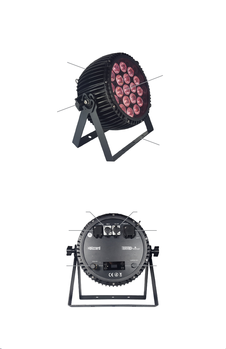
Figure 1: The Tournado™ WiMAX Quadra Pin-Up Picture
Heavy-Duty Cast
Aluminum Enclosure
19x 15W 4-in-1
RGBW LEDs
Locking
Adjustment
Knobs
Dual
Mounting
Yokes
Figure 2: The Rear Connections
DMX In
Power In
Antenna
Tournado™ WiMAX Quadra Manual Rev. A Copyright 2018 Blizzard Lighting, LLC
Page 6
DMX Out
Power Out
OLED Menu
Page 7
3. SETUP
Before replacing a fuse, disconnect the power cord.
ALWAYS replace with the same type and rating of fuse.
Fuse Replacement
CAUTION! The Tournado™ WiMAX Quadra utilizes a high-output switch-mode power
supply with an internal fuse. Under normal operating conditions, the fuse should not
require replacement. Should your xture require fuse replacement, please contact
Blizzard Lighting for instructions.
Data/DMX Cabling
For wired connections you’ll need to use data-grade DMX cables. Also, be sure to set
the xture signal input in the menu to cable: SET > SIGN > CABL.
Fixtures on a serial data link must be daisy chained in one single line. Also,
connecting more than 32 xtures on one serial data link without the use of a DMX
optically-isolated splitter may result in deterioration of the digital DMX signal. The
maximum recommended cable-run distance is 500 meters (1640 ft). The maximum
recommended number of xtures on a serial data link is 32 xtures.
Using The Built-in W-DMX™
In addition to the unbridled thrill you already received the rst time you turned it
on, you’ll be delighted to know that this unit is designed to work seamlessly with any
W-DMX™ product. W-DMX™ is a two-time award winning wireless DMX technology,
created and owned by Wireless Solution Sweden AB.
To use the built-in W-DMX™ receiver, you will rst need a W-DMX™ transmitter
or transceiver to broadcast the signal, such as our own LightCaster™ W-DMX™
transceiver unit. Paired up with a LightCaster™ W-DMX™ transceiver, you can
expect an outstanding wireless range of up to 500 meters (line-of-sight), and leave
any worries behind concerning loss of signal due to its built-in FHSS technology
(Frequency Hopping Spread Spectrum).
FHSS are frequency hopping techniques, in which the
transmitter jumps from one sub-channel to another
at a very rapid pace. This technique was rst used by
the U.S. military precisely because they are dicult
to disrupt, and unless you knew the frequency
hopping sequence, practically impossible to intercept.
Make sure to read the instruction manual of your
LightCaster™ W-DMX™, or other W-DMX™ transmission device for other product
specic setup information.
Tournado™ WiMAX Quadra Manual Rev. A Copyright 2018 Blizzard Lighting, LLC
Page 7
Page 8
Ready to move on? Well alrighty!
Plug your wireless W-DMX transmitter into the “DMX OUT” of your controller. Please
refer to your transmitting device user manual for further setup instruction.
a. One transceiver with multiple receivers:
1.) Power on all W-DMX receiving xtures, and verify that the signal input in the
xture menus are set to wireless: SET > SIGN > 2.4G.
2.) On the receiving xtures, navigate to SET > WIRE > KEY, and then press
and hold <ENTER> for 3 seconds.
3.) Verify that your W-DMX transmitter is transmitting signal.
4.) The receiving xtures should now be synced.
b. Multiple transceivers, multiple receivers; e.g. 3 groups consisting of a
transceiver & receiver(s) named A, B, and C:
1.) Turn power o of all units.
2.) Group “A” gets powered on, then follow steps above.
3.) Group “B” gets powered on, then follow steps above.
4.) Group “C” gets powered on, then follow steps above.
3-Pin??? 5-Pin??? Huh?!?
If you use a controller with a 5 pin DMX output connector, you will need to use a 5 pin to 3 pin adapter.
They are widely available over the internet and from specialty retailers. If you’d like to build your own, the
chart below details a proper cable conversion:
Conductor 3-Pin Female (Output) 5-Pin Male (Input)
Ground/Shield Pin 1 Pin 1
Data 1- (Primary Data Link) Pin 2 Pin 2
Data 1+ (Primary Data Link) Pin 3 Pin 3
Data 2- (Optional Secondary Data Link) Pin 4 Pin 4
Data 2+ (Optional Secondary Data Link) Pin 5 Pin 5
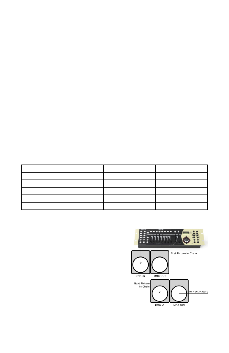
Take It To The Next Level: Setting Up DMX Control
Step 1: Connect the male connector of the
DMX cable to the female connector (output)
on the controller.
Step 2: Connect the female connector of
the DMX cable to the rst xture’s male
connector (input). Note: It doesn’t matter
which xture address is the rst one
connected. We recommend connecting
the xtures in terms of their proximity to
the controller, rather than connecting the
lowest xture number rst, and so on.
Step 3: Connect other xtures in the chain
from output to input as above. Place a
DMX terminator on the output of the nal xture to ensure best communication.
Tournado™ WiMAX Quadra Manual Rev. A Copyright 2018 Blizzard Lighting, LLC
Page 8
Page 9

Fixture Linking (Master/Slave Mode)
1. Connect the (male) 3-pin connector side of the DMX cable
to the output (female) 3-pin connector of the rst xture.
2. Connect the end of the cable coming from the rst xture
which will have a (female) 3-pin connector to the input
connector of the next xture consisting of a (male) 3-pin
connector. Then, proceed to connect from the output as stated
above to the input of the following xture and so on.
A quick note: Often, the setup for Master-Slave and Standalone operation requires
that the rst xture in the chain be initialized for this purpose via either settings
in the control panel or DIP-switches. Secondarily, the xtures that follow may also
require a slave setting.
Check the “Operating
Adjustments” section in
this manual for complete
instructions for this type of
setup and conguration.
Mounting & Rigging
This xture may be mounted
in any SAFE position
provided there is enough
room for ventilation.
It is important never to
obstruct the fan or vents
pathway. Mount the xture
using a suitable “C” or “O”
should be rated to hold at least 10x the xture’s weight to ensure structural stability.
Do not mount to surfaces with unknown strength, and ensure properly “rated”
rigging is used when mounting xtures overhead.
type clamp. The clamp
Adjust the angle of the xture by loosening both knobs and tilting the xture. After
nding the desired position, retighten both knobs.
• When selecting installation location, take into consideration lamp replacement
access (if applicable) and routine maintenance.
• Safety cables MUST ALWAYS be used.
• Never mount in places where the xture will be exposed to rain, high humidity,
extreme temperature changes or restricted ventilation.
Tournado™ WiMAX Quadra Manual Rev. A Copyright 2018 Blizzard Lighting, LLC
Page 9
Page 10

4. OPERATING ADJUSTMENTS
The Control Panel
All the goodies and dierent modes possible with your Tournado™ WiMAX
xture are accessed by using the control panel on the rear of the xture. There
are 4 control buttons which allow you to navigate through the various control
panel menus.
<MENU>
Is used to navigate to the previous higher-level menu item.
<ENTER>
Is used to select and conrm/store the current selection.
<UP>
Scrolls through menu items and numbers in ascending order.
<DOWN>
Scrolls through menu items and numbers in descending order.
The control panel display shows the menu items you select from the menu map
on page #11. When a menu function is selected, the display will show immedi-
ately the rst available option for the selected menu function. To select a menu
item, press <ENTER>.
Use the <UP> and <DOWN> buttons to navigate the menu options. Press the
<ENTER> button to select the menu function currently displayed, or to enable
a menu option. To return to the previous option or menu without changing the
value, press the <MENU> button.
Tournado™ WiMAX Quadra Manual Rev. A Copyright 2018 Blizzard Lighting, LLC
Page 10
Page 11

Control Panel Menu Structure
ADDR 001-512 To choose the DMX address
STAT R Red intensity (0% <--> 100%)
G Green intensity (0% <--> 100%)
B Blue intensity (0% <--> 100%)
W White intensity (0% <--> 100%)
SHUT Flash / strobe speed (0-255)
PRSC (preset colors) NONE, R, G, B, W, RGW, RGB, YELLOW, PINK, CYAN, ORANGE, VIO-
SET SIGN <ENTER> Choose the signal type: 2.4G (wireless) or CABL (cable)
WIRE <ENTER> Wireless Reset: REST, or KEY desired wireless mode (color coded
CAL To set global intensity levels of each color + USE: YES/NO
CHMD 10CH To run in 10-channel mode
6CH To run in 6-channel mode
4CH To run in 4-channel mode
DIM
(dimming)
LOCK YES/NO To unlock, press the buttons in this order: <MENU>, <UP>,
CTST CT01-CT10 <ENTER> R/G/B/W adjustments for custom color banks 01-10
AUTO AT01-AT05 <ENTER> Auto programs 1-5
ATSP <ENTER> Auto Speed
CHS1 <ENTER> Custom program 1
CHS2 <ENTER> Custom program 2
CHS3 <ENTER> Custom program 3
PROG CHS1-
CHS3
Custom
programs
1-3.
INFO SOFT Vx.x Software version information
LOAD ST L Restore factory settings
PR L Restore factory program settings
SEND YES/NO Sync settings between xtures via DMX
LIN Linear dimming curve
SQR Square law curve
ISQR Inverse square law curve
SCUR S-curve
LIN. Linear dimming curve (smooth)
SQR. Square law curve (smooth)
ISQR. Inverse square law curve (smooth)
SCUR. S-curve (smooth)
SC01-SC20
20 scenes
for each
custom
program.
POW Current automated overheat protection level (100%/80%/50%)
LET, GOLDEN, 2700K, 3200K, 4000K, 5500K, 6500K, RGBW
LED)
<DOWN>, <ENTER> 3x times in a row with no longer than 2 sec-
onds between each button press.
R (0-255) AUTO (None, AT01-AT05)
G (0-255) ATSP (speed, 0-255)
B (0-255) TIME (duration, 0-255)
W (0-255) WAIT (before fade, 0-255)
SHUT (strobe,
0-255)
USE (use scene, YES/NO)
Tournado™ WiMAX Quadra Manual Rev. A Copyright 2018 Blizzard Lighting, LLC
Page 11
Page 12

DMX Mode
Allows the unit to be controlled by any universal DMX controller.
Setting the DMX Address:
1.) The default mode for the xture is DMX, which appears as 001 on the LED readout. To
select a dierent DMX address, using the <MENU> button, select ADDR, then hit <ENTER>.
Use the <UP/DOWN> buttons to select the correct address, then hit <ENTER> to conrm.
Setting the DMX Channel Mode:
1.) To select a DMX channel mode, press the <MENU> button, then use the <UP/DOWN>
buttons until the display reads SET and press the <ENTER> button. Then use the <UP/
DOWN> buttons until the display reaches CHMD, and press <ENTER>. Now press the <UP/
DOWN> buttons again to highlight your desired DMX channel mode, and press the <ENTER>
button to conrm.
Slave Mode:
1.) Daisy chain the xtures DMX in/out, having the controller at the beginning of the line.
2.) There is nothing else to it! The rst xture in the DMX chain is the master xture, and the
following xtures will follow the master.
Dimming Mode Settings:
Allows users to set the xture to use 1 of 4 (x2) dimming curve settings for smoother (and slower)
dimming capabilities. In the control panel menu, there are two settings for each curve that are
distinguishable from one another by the trailing dot.
Linear Curve Square Law Inverse Square Law S-Curve
(LIN, LIN.) (SQR, SQR.) (ISQR, ISQR.) (SCUR, SCUR.)
Output
DMX% DMX% DMX% DMX%
*The curve settings with the trailing dot adds a bit more delay to the curve for a smoother eect.
1.) Use the <MENU> and <UP/DOWN> buttons to navigate to SET and press <ENTER>,
then <UP/DOWN> buttons again to scroll to DIM, and press the <ENTER> button.
2.) Now use the <UP/DOWN> buttons to highlight either LIN (Linear), SQR (Square), ISQR
(Inverse Square), SCUR (S-Curve), LIN. (Smooth Linear), SQR. (Smooth Square), ISQR.
(Smooth Inverse Square), or SCUR. (Smooth S-Curve), then hit <ENTER>.
Tournado™ WiMAX Quadra Manual Rev. A Copyright 2018 Blizzard Lighting, LLC
Output
Output
Page 12
Output
Page 13

Custom Programs:
Allows users to create up to 3 customizable, 20 scene programs that are directly accessible via the control
panel and also in DMX mode.
Creating A Custom Program:
1.) Use the <MENU> and <UP/DOWN> buttons to navigate to PROG, and press <ENTER>.
2.) Now use the <UP/DOWN> buttons to highlight your choice of either CHS1, CHS2, or
CHS3 and press <ENTER>.
3.) Start with editing scene 1 (SC01), customizing it to your liking by using the choices outlined
in the table below. You can insert any of its 5 built-in auto programs (AT01-AT05), and adjust
its speed (ATSP 0-255), and also set the duration (in seconds) before moving on to the next
scene (TIME 0-255). You can also add a fade in eect to the start of this scene (WAIT 0-255),
and/or strobe (SHUT 0-255). Finally, if you want to use this scene in your program, be sure to
enable it (USE: YES/NO).
4.) Repeat the above process to create up to 20 scenes in each of the 3 customizable programs.
R (0-255) - Red Intensity AUTO (AT01-AT05) - Auto Programs
G (0-255) - Green Intensity ATSP (0-255) - Auto Speed (fast - slow)
B (0-255) - Blue Intensity TIME (0-255) - Scene Time (seconds)
W (0-255) - White Intensity WAIT (0-255) - Fade In (fast - slow)
SHUT (0-255) - Strobe (slow - fast) USE (YES/NO) Use Scene in Program?
Running A Custom Program:
1.) To view your newly created lighting masterpiece, use the <MENU> and <UP/DOWN>
buttons to navigate to AUTO, and press <ENTER>.
2.) Use the <UP/DOWN> buttons to highlight your choice of CHS1, CHS2, or CHS3 and press
<ENTER>. These are directly accessible from the built-in program channel in DMX mode.
IMPORTANT:
If USE is set to NO, or TIME is set
to 0, the scene will not run!
Auto, Modes, and Auto Speed:
Set single or Master/Slaved units to run auto modes at user selectable speeds.
Auto Mode:
1.) Use the <MENU> and <UP/DOWN> buttons to navigate to navigate to AUTO, and press
the <ENTER> button.
2.) Now use the <UP/DOWN> buttons to highlight any program ranging from AT01-AT05,
and press <ENTER>.
Auto Speed:
1.) Use the <MENU> and <UP/DOWN> buttons to navigate to AUTO and press <ENTER>,
then with the <UP/DOWN> buttons navigate to ATSP, and press the <ENTER> button.
2.) Make a selection from 0-255, and press <ENTER> to choose a speed (slow <--> fast).
Tournado™ WiMAX Quadra Manual Rev. A Copyright 2018 Blizzard Lighting, LLC
Page 13
Page 14

Color Calibration Settings:
Allows the user to setup and save 1 customized R/G/B/W color balance setting and save it for future use.
This custom setting is global, and it will eect all modes.
1.) Use the <MENU> and <UP/DOWN> buttons to navigate to SET and press <ENTER>,
then on while CAL, push <ENTER> again.
2.) Use the <UP/DOWN> buttons to highlight either R (Red Level), G (Green Level), B (Blue
Level), or W (White Level), then hit <ENTER>.
3.) Now using the <UP/DOWN> buttons, select the maximum level for each color between
000-255 (000=o), and hit <ENTER> to conrm your choice.
4.) You have now just setup and saved a custom global color calibration setting that you can use
at you convenience. To use your custom setting now (or later), press the <UP/DOWN> buttons
to reach USE, and press <ENTER>. Then choose either YES or NO and press <ENTER>. When
you select YES, it enables this custom color calibration globally, and when choosing NO the
xture will continue to use the default color calibration settings. Your customized settings will
be saved for later use even after powering o the xture. It can be altered to your liking at any
time. Just remember to return to this setting to either enable or disable it when needed.
Custom Static Colors & Preset Colors:
Allows the user to create and save custom static colors for use in standalone or DMX mode.
Static Color Mixing and Preset Mixed Colors
Important: When nished editing and saving a static color, you must return to (and stay
on) any one of the editing screens (0-255) to make the eect stay on continually. If you were
only to press <ENTER> to save your nal edit, you would again be on the static color/eect
selection menu, which from here will result in blackout mode after 1 minute.
1.) Use the <MENU> and <UP/DOWN> buttons to navigate to STAT and press <ENTER>,
then <UP/DOWN> buttons to select R/G/B/W, and push <ENTER> to conrm your selection.
Then in adjust the values (0-255) to your liking and press <ENTER> to save.
2.) In the same manner, you can select SHUT to add a strobe eect.
3.) You can also select <PRSC> and use the <UP/DOWN> buttons to scroll through and
quickly use any of the xtures built-in preset colors.
Mix and Save Custom Colors (1-10)
1.) Use the <MENU> and <UP/DOWN> buttons to navigate to CTST and press <ENTER>,
then <UP/DOWN> buttons to select a color bank from CT01-CT10, and push <ENTER> to
conrm your selection.
2.) Now use the <UP/DOWN> buttons to highlight either R (Red Level), G (Green Level), B
(Blue Level), or W (White Level), then hit <ENTER>.
3.) Finally, using the <UP/DOWN> buttons, select the maximum level for each color between
000-255 (000=o), and hit <ENTER> to conrm your choice(s).
4.) These 10 custom colors can be accessed and edited to your liking at any time, and will be
saved even after powering o the xture.
5.) Your custom colors and programs are also directly accessible from the built-in program
channel in DMX mode.
Tournado™ WiMAX Quadra Manual Rev. A Copyright 2018 Blizzard Lighting, LLC
Page 14
Page 15

Fixture Reset Functions:
Allows users to reset the xture to factory default settings, without loosing customized settings, or reset
the custom programs exclusively.
1.) Use the <MENU> and <UP/DOWN> buttons to navigate to LOAD and press <ENTER>,
then use the <UP/DOWN> buttons to highlight ST L or PR L, and press <ENTER>.
2.) Use the <UP/DOWN> buttons to highlight either YES or NO, then press <ENTER>.
3.) The ST L reset function will reset all default values with the exception of those in ADDR
(address), CTST (10 custom colors), and PROG (custom scenes and programs).
4.) The PR L reset function will only reset all customized program settings found in the PROG
settings (custom scenes and programs).
Data Sync Feature:
Users can transfer their custom settings from one xture to another via DMX.
1.) Disconnect xtures from any DMX controllers, and link them together via DMX in/out.
2.) On the sending xture (DMX out), navigate the main menu using the <UP/DOWN> buttons
to reach SEND, and press the <ENTER> button.
3.) Select YES, and press the <ENTER> button to begin the transfer.
4.) Information for ADDR (address), or CAL (global intensity) will not be sent.
5.) After the data has been transferred, the receiving xture will be automatically be reset.
Fixture Information:
These are not editable features, they are for informational purposes only.
1.) Use the <MENU> and <UP/DOWN> buttons to navigate to INFO and press <ENTER>,
then use the <UP/DOWN> buttons to highlight SOFT or POW, and press <ENTER>.
2.) The SOFT information simply displays the current software version installed on the xture,
and POW displays the xtures current power level setting. Under normal conditions, it will be
at 100%... but this xture has built-in overheat protection that may automatically reduce the
output level to 80%, or 50% in high temperature situations.
Tournado™ WiMAX Quadra Manual Rev. A Copyright 2018 Blizzard Lighting, LLC
Page 15
Page 16

DMX Values In-Depth (4/6/10-Channel Modes)
4CH 6CH 10CH Value What It Does
-- 1 1 000 <--> 255 Dimmer (0% <--> 100%)
1 2 2 000 <--> 255 Red Intensity (0% <--> 100%)
2 3 3 000 <--> 255 Green Intensity (0% <--> 100%)
3 4 4 000 <--> 255 Blue Intensity (0% <--> 100%)
4 5 5 000 <--> 255 White Intensity (0% <--> 100%)
-- 6 6
-- -- 7
000 <--> 005
006 <--> 020
021 <--> 060
061 <--> 100
101 <--> 140
141 <--> 180
181 <--> 220
221 <--> 255
000 <--> 005
006 <--> 010
011 <--> 015
016 <--> 020
021 <--> 025
026 <--> 030
031 <--> 035
036 <--> 040
041 <--> 045
046 <--> 050
051 <--> 055
056 <--> 060
061 <--> 065
066 <--> 070
071 <--> 075
076 <--> 080
081 <--> 110
111 <--> 115
116 <--> 120
121 <--> 125
126 <--> 130
131 <--> 135
136 <--> 140
141 <--> 145
146 <--> 150
151 <--> 155
156 <--> 160
161 <--> 165
166 <--> 170
171 <--> 175
176 <--> 180
181 <--> 185
186 <--> 190
191 <--> 195
196 <--> 200
201 <--> 220
221 <--> 225
226 <--> 230
231 <--> 235
236 <--> 255
Strobe
No strobe
Non-synchronous strobe (slow <--> fast)
Synchronous strobe (slow <--> fast)
Electronic sine wave (slow <--> fast)
Random strobe (slow <--> fast)
Opening pulse (slow <--> fast)
Closing pulse (slow <--> fast)
Electronic square wave (slow <--> fast)
Built-In Programs
No Function
Custom color 1 (CT01 in menu settings)
Custom color 2 (CT02 in menu settings)
Custom color 3 (CT03 in menu settings)
Custom color 4 (CT04 in menu settings)
Custom color 5 (CT05 in menu settings)
Custom color 6 (CT06 in menu settings)
Custom color 7 (CT07 in menu settings)
Custom color 8 (CT08 in menu settings)
Custom color 9 (CT09 in menu settings)
Custom color 10 (CT10 in menu settings)
Auto 1
Auto 2
Auto 3
Auto 4
Auto 5
Reserved
Red
Green
Blue
White
RGW
RGB
Yellow
Pink
Cyan
Orange
Violet
Golden
2700K White
3200K White
4000K White
5500K White
6500K White
RGBW
No Function
Custom program 1 (CH01 in menu settings)
Custom program 2 (CH02 in menu settings)
Custom program 3 (CH03 in menu settings)
No Function
Tournado™ WiMAX Quadra Manual Rev. A Copyright 2018 Blizzard Lighting, LLC
Page 16
Page 17

DMX Values In-Depth (4/6/10-Channel Modes), continued
4CH 6CH 10CH Value What It Does
-- -- 8 000 <--> 255 Auto Speed (slow <--> fast)
-- -- 9
-- -- 10
000 <--> 010
011
012 <--> 050
051
052 <--> 090
091
092 <--> 130
131
132 <--> 170
171
172 <--> 210
211
212 <--> 250
251 <--> 255
000 <--> 010
011 <--> 020
021 <--> 030
031 <--> 040
041 <--> 050
051 <--> 060
061 <--> 070
071 <--> 080
081 <--> 090
091 <--> 255
Virtual Color Wheel
No Function
Blue
Blue (+ green)
Teal
Teal (- blue)
Green
Green (+ red)
Yellow
Yellow (- green)
Red
Red (+ blue)
Magenta
Magenta (- red)
Blue
Dimming Mode
Default (as set in the LED menu)
Linear curve
Square law curve
Inverse square law curve
S-curve
Linear curve (smooth)
Square law curve (smooth)
Inverse square law curve (smooth)
S-curve (smooth)
Default (as set in the LED menu)
Troubleshooting
Symptom Solution
Fixture Auto-Shut OCheck the fan in the xture. If it is stopped or moving slower than
No Light Output Check to ensure xture is operating under correct mode, IE auto/
Chase Speed Too
Fast/Slow
No Power Check AC cord and circuit for malfunction.
Blown Fuse Check AC cord and circuit for damage, verify that moving parts are
Fixture Not
Responding /
Responding Erratically
Tournado™ WiMAX Quadra Manual Rev. A Copyright 2018 Blizzard Lighting, LLC
normal, the unit may have shut itself o due to high heat. This is to
protect the xture from overheating. Clear the fan of obstructions,
or return the unit for service.
DMX/Etc., if applicable.
Check to ensure proper setup of speed adjustment.
not restricted and that unit’s ventilation is not obstructed
Make sure all connectors are seated properly and securely.
Use Only DMX Cables and/or check cables for defects
Install a Terminator.
Reset xture(s).
Page 17
Page 18

5. APPENDIX
A Quick Lesson On DMX
DMX (aka DMX-512) was created in 1986 by the United States Institute for Theatre
Technology (USITT) as a standardized method for connecting lighting consoles to lighting
dimmer modules. It was revised in 1990 and again in 2000 to allow more exibility. The
Entertainment Services and Technology Association (ESTA) has since assumed control over
the DMX512 standard. It has also been approved and recognized for ANSI standard clas-
sication.
DMX covers (and is an abbreviation for) Digital MultipleXed signals. It is the most common
communications standard used by lighting and related stage equipment.
DMX provides up to 512 control “channels” per data link. Each of these channels was originally intended to control lamp dimmer levels. You can think of it as 512 faders on a lighting
console, connected to 512 light bulbs. Each slider’s position is sent over the data link as an
8-bit number having a value between 0 and 255. The value 0 corresponds to the light bulb
being completely o while 255 corresponds to the light bulb being fully on.
DMX data is transmitted at 250,000 bits per second using the RS-485 transmission standard over two wires. As with microphone cables, a grounded cable shield is used to prevent
interference with other signals.
There are ve pins on a DMX connector: a wire for ground (cable shield), two wires for
“Primary” communication which goes from a DMX source to a DMX receiver, and two wires
for a “Secondary” communication which goes from a DMX receiver back to a DMX source.
Generally, the “Secondary” channel is not used so data ows only from sources to receivers. Hence, most of us are most familiar with DMX-512 as being employer over typical
3-pin “mic cables,” although this does not conform to the dened standard.
DMX is connected using a daisy-chain conguration where the source connects to the input
of the rst device, the output of the rst device connects to the input of the next device,
and so on. The standard allows for up to 32 devices on a single DMX link.
Each receiving device typically has a means for setting the “starting channel number” that
it will respond to. For example, if two 6-channel xtures are used, the rst xture might
be set to start at channel 1 so it would respond to DMX channels 1 through 6, and the next
xture would be set to start at channel 7 so it would respond to channels 7 through 12.
The greatest strength of the DMX communications protocol is that it is very simple and
robust. It involves transmitting a reset condition (indicating the start of a new “packet”),
a start code, and up to 512 bytes of data. Data packets are transmitted continuously. As
soon as one packet is nished, another can begin with no delay if desired (usually another
follows within 1 ms). If nothing is changing (i.e. no lamp levels change) the same data will
be sent out over and over again. This is a great feature of DMX -- if for some reason the
data is not interpreted the rst time around, it will be re-sent shortly.
Not all 512 channels need to be output per packet, and in fact, it is very uncommon to nd
all 512 used. The fewer channels are used, the higher the “refresh” rate. It is possible to
get DMX refreshes at around 1000 times per second if only 24 channels are being transmitted. If all 512 channels are being transmitted, the refresh rate is around 44 times per
second.
In summary, since its design and evolution in the 1980’s DMX has become the standard
for lighting control. It is exible, robust, and scalable, and its ability to control everything
from dimmer packs to moving lights to foggers to lasers makes it an indispensable tool for
any lighting designer or lighting performer.
Tournado™ WiMAX Quadra Manual Rev. A Copyright 2018 Blizzard Lighting, LLC
Page 18
Page 19

Keeping Your Tournado™ WiMAX Quadra As Good As New
The xture you’ve received is a rugged, tough piece of pro lighting equipment, and as long as you take care of it, it will take care of you. That said, like
anything, you’ll need to take care of it if you want it to operate as designed.
You should absolutely keep the xture clean, especially if you are using it in an
environment with a lot of dust, fog, haze, wild animals, wild teenagers or spilled
drinks.
Cleaning the optics routinely with a suitable glass cleaner will greatly improve
the quality of light output. Keeping the fans free of dust and debris will keep
the xture running cool and prevent damage from overheating.
In transit, keep the xtures in cases. You wouldn’t throw a prized guitar,
drumset, or other piece of expensive gear into a gear trailer without a case,
and similarly, you shouldn’t even think about doing it with your shiny new light
xtures.
Common sense and taking care of your xtures will be the single biggest thing
you can do to keep them running at peak performance and let you worry about
designing a great light show, putting on a great concert, or maximizing your client’s satisfaction and “wow factor.” That’s what it’s all about, after all!
Returns (Gasp!)
We’ve taken a lot of precautions to make sure you never even have to worry
about sending a defective unit back, or sending a unit in for service. But, like
any complex piece of equipment designed and built by humans, once in a while,
something doesn’t go as planned. If you nd yourself with a xture that isn’t
behaving like a good little xture should, you’ll need to obtain a Return Authori-
zation (RA).
Don’t worry, this is easy. Just open a support ticket at www.blizzardlighting.
com/support, and we’ll issue you an RA. Then, you’ll need to send the unit to
us using a trackable, pre-paid freight method. We suggest using USPS Priority
or UPS. Make sure you carefully pack the xture for transit, and whenever possible, use the original box & packing for shipping.
When returning your xture for service, be sure to include the following:
1.) Your contact information (Name, Address, Phone Number, Email address).
2.) The RA# issued to you
3.) A brief description of the problem/symptoms.
We will, at our discretion, repair or replace the xture. Please remember that
any shipping damage which occurs in transit to us is the customer’s responsibility, so pack it well!
Shipping Issues
Damage incurred in shipping is the responsibility of the shipper, and
must be reported to the carrier immediately upon receipt of the items.
Claims must be made within seven (7) days of receipt.
Tournado™ WiMAX Quadra Manual Rev. A Copyright 2018 Blizzard Lighting, LLC
Page 19
Page 20

Tech Specs!
Weight & Dimensions
Width 14 inches (35.5 cm)
Depth 6.7 inches (17.2 cm)
Height 13.3 inches (33.7 cm)
Weight 17 lbs (7.7 kg)
Power
Operating Voltage AC 100V-264V/47-63HZ
Power Consumption 180W, 1.54A, PF: .99
Light Source
LED 19x 15W 4-in-1 RGBW LEDs, 100,000 hours.
Optical
Beam Angle 25-degree beam
Thermal
Max. Operating Temp. 104 degrees F (40 degrees C) ambient
Control
Protocol USITT DMX-512
DMX Channels 4/6/10-channel DMX modes
Input/Output 3-pin XLR Male/Female
Other Operating Modes DMX512, M/S, Standalone, Auto Mode
Warranty
2-year limited warranty, does not cover malfunction caused by
damage to LEDs.
Photometric Data
25° Beam Angle
Distance:
Diameter:
Luminous Intensity:
Beam Lux fc Lux fc Lux fc Lux fc
25° 18,441 1,713.2 8,893 826.2 5,313 493.6 3,415 317.3
Tournado™ WiMAX Quadra Manual Rev. A Copyright 2018 Blizzard Lighting, LLC
2m
35.5" (90 cm)
3m
53" (135 cm)
4m
70.9" (180 cm)
5m
88.6" (225 cm)
2-meter 3-meter 4-meter 5-meter
Page 20
Page 21

Dimensional Drawings
13.3 inches (33.7 cm)
14 inches (35.5 cm)
6.7 inches (17.2 cm)
Tournado™ WiMAX Quadra Manual Rev. A Copyright 2018 Blizzard Lighting, LLC
Page 21
Page 22

This page intentionally left blank.
Tournado™ WiMAX Quadra Manual Rev. A Copyright 2018 Blizzard Lighting, LLC
Page 22
Page 23

This page intentionally left blank.
Tournado™ WiMAX Quadra Manual Rev. A Copyright 2018 Blizzard Lighting, LLC
Page 23
Page 24

Enjoy your product!
Our sincerest thanks for your purchase!
--The team @ Blizzard Lighting
 Loading...