

Page 1
Blizzard Lighting, LLC
www.blizzardlighting.com
Waukesha, WI USA
Copyright (c) 2013
Page 2

TABLE OF CONTENTS
HotBox™ LED 1
1. Getting Started 3
What’s In The Box? 3
Getting It Out Of The Box 3
Powering Up! 3
Getting A Hold Of Us 3
Safety Instructions (Don’t Stick Your Hand In The Toaster!) 4
2. Meet The HotBox™ LED 5
Features 5
DMX Quick Reference 5
The HotBox™ Pin-up Picture 6
3. Setup 7
Fuse Replacement 7
Connecting A Bunch Of HotBox™ PAR Cans 7
Data/DMX Cables 7
Wicicle Wirelss DMX System 8-9
Cable Connectors 10
3-Pin??? 5-Pin??? Huh? 10
Take It To The Next Level: Setting up DMX Control 10
Fixture Linking (Master/Slave Mode) 11
Mounting/Rigging 11
4. Operating Adjustments 12
Navigating The Control Panel 12
Control Panel Menu Structure 13
DMX Mode 14
Master/Slave Mode 14
Sound Active Mode 14
Standalone (Program) Mode 14
Manual Color Adjustment 14
DMX Channel Values In-Depth 15
Troubleshooting 16
5. Appendix 17
A Quick DMX Lesson 17
Keeping Your HotBox™ As Good As New 18
Returns (Gasp!) 18
Shipping Issues 18
Tech Specs 19
HotBox Manual Rev. A © 2013 Blizzard Lighting, LLC
Page 2
Page 3

1. GETTING STARTED
What’s In The Box?
• 1 x HotBox™ Professional LED PAR Fixture
• A totally rockin’ DMX Cable
• This Lovely User Manual
Getting It Out Of The Box
Congratulations on purchasing one of the most rocking box-shaped PAR xtures
anywhere! Now that you’ve got your HotBox™ (or hopefully, HotBoxes!), you should
carefully unpack the box and check the contents to ensure that all parts are present
and in good condition. If anything looks as if it has been damaged in transit, notify the
shipper immediately and keep the packing material for inspection. Again, please save
the carton and all packing materials. If a xture must be returned to the factory, it is
important that the xture be returned in the original factory box and packing.
Powering Up!
All xtures must be powered directly off a switched circuit and cannot be run off a
rheostat (variable resistor) or dimmer circuit, even if the rheostat or dimmer
channel is used solely for a 0% to 100% switch.
AC Voltage Switch - Not all xtures have a voltage select switch, so please verify that
the xture you receive is suitable for your local power supply. See the label on the
xture or refer to the xture’s specications chart for more information. A xture’s
listed current rating is its average current draw under normal conditions. Check the
xture or device carefully to make sure that if a voltage selection switch exists that it is
set to the correct line voltage you will use.
Warning! Verify that the voltage select switch on your unit matches the line
voltage applied. Damage to your xture may result if the line voltage applied
does not match the voltage indicated on the voltage selector switch. All
xtures must be connected to circuits with a suitable Ground (Earthing).
Getting A Hold Of Us
If something is wrong, just give us a call or send an email. We’ll be happy to
help, honest.
Blizzard Lighting
N16 W23390 Stoneridge Dr. Suite E
Waukesha, WI 53188 USA
www.blizzardlighting.com
414-395-8365
Email: [email protected]
Disclaimer: The information and specications contained in this document are subject
to change without notice. Blizzard Lighting™ assumes no responsibility or liability
for any errors or omissions that may appear in this user manual. Blizzard Lighting™
reserves the right to update the existing document or to create a new document to
correct any errors or omissions at any time. You can download the latest version of this
document from www.blizzardlighting.com.
Author: Date: Last Edited: Date:
J. Thomas 2/26/2013 J. Keeley 3/25/2013
HotBox Manual Rev. A © 2013 Blizzard Lighting, LLC
Page 3
Page 4

SAFETY INSTRUCTIONS
• Please keep this User Guide for future use. If you sell the unit to someone
else, be sure that they also receive this User Guide.
• ALWAYS make sure that you are connecting to the proper voltage, and that
the line voltage you are connecting to is not higher than that stated on the de-
cal or rear panel of the xture.
• This product is intended for indoor use only.
• To prevent risk of re or shock, do not expose xture to rain or moisture.
• Make sure there are no ammable materials close to the unit while operating.
• The unit must be installed in a location with adequate ventilation, at least
20in (50cm) from adjacent surfaces. Be sure that no ventilation slots are
blocked.
• ALWAYS disconnect from the power source before servicing or replacing fuse
and be sure to replace with same fuse size and type.
• ALWAYS secure xture using a safety chain. NEVER carry the xture by its
cord. Use its carrying handles.
• DO NOT operate at ambient temperatures higher than 104°F (40°C).
• In the event of a serious operating problem, stop using the unit immediately.
NEVER try to repair the unit by yourself. Repairs carried out by unskilled people
can lead to damage or malfunction. Please contact the nearest authorized technical assistance center. Always use the same type spare parts.
• NEVER connect the device to a dimmer pack.
• Make sure the power cord is never crimped or damaged.
• Never disconnect the power cord by pulling or tugging on the cord.
• Avoid direct eye exposure to the light source while it is on.
Caution! There are no user serviceable parts inside the unit. Do not
open the housing or attempt any repairs yourself. In the unlikely event
your unit may require service, please contact Blizzard Lighting at sup[email protected].
HotBox Manual Rev. A © 2013 Blizzard Lighting, LLC
Page 4
Page 5
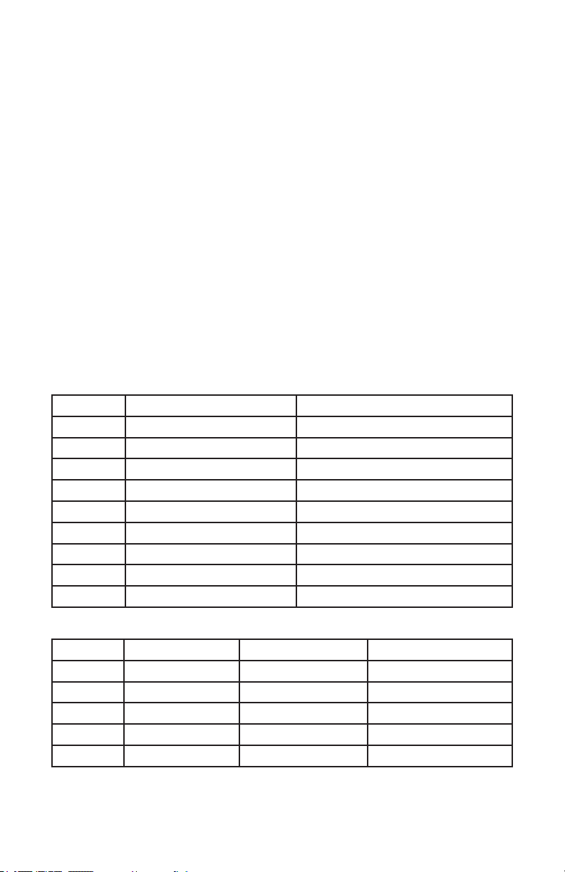
2. MEET THE HOTBOX™ LED PAR
CONTROL FEATURES
• RGBW color mixing via 7x 10W Red/Green/Blue/White 4-in-1 LEDs
• Variable electronic dimming & strobe
• Built-in color & chase macros via DMX
• Built-in automated programs via master/slave
• Built-in sound active programs
• RGBW color mixing ability in standalone mode
• HSV (3-Ch), RGBW (4-Ch), RGBW + Dimmer (5-Ch) & Extended (8-
Ch) DMX Proles
ADDITIONAL FEATURES
• Rugged and well-built (It hits the gym regularly)
• Super-quiet variable-speed internal Fan Cooling
• Dual mounting brackets for positioning exibility
• Flicker-free constant-current 400hz LED driver
• 3-pin male input and 3-pin female output
• PowerCon™ compatible AC power In/Out connectors
DMX Quick Reference - 8 / 9 Channel Mode
Channel 8 Channel 9 Channel
1 Dimmer Dimmer
2 Red Intensity Red Intensity
3 Green Intensity Green Intensity
4 Blue Intensity Blue Intensity
5 White Intensity White Intensity
6 Strobe Strobe
7 Built-in Programs Built-in Programs
8 Program Speed Program Speed
9 --- 32-Bit Dimmer
DMX Quick Reference - 3 (HSV) / 4 / 5 Channel Mode
Channel HSV 4 Channel 5 Channel
1 Hue Red Intensity Dimmer
2 Saturation Green Intensity Red Intensity
3 Value Blue Intensity Green Intensity
4 --- White Intensity Blue Intensity
5 --- --- White Intensity
HotBox Manual Rev. A © 2013 Blizzard Lighting, LLC
Page 5
Page 6
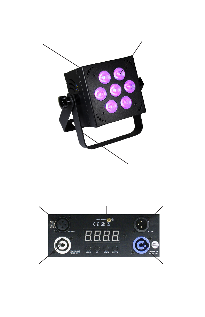
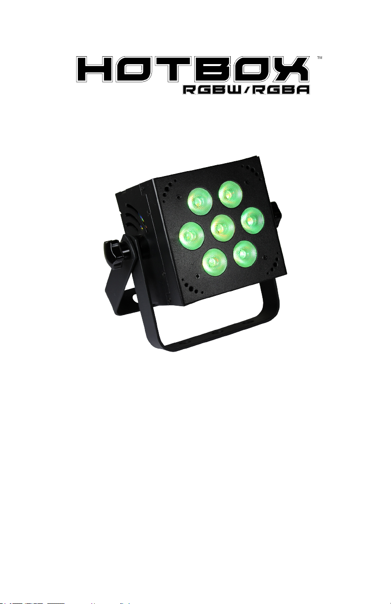
Figure 1: The HotBox™ Pin-Up Picture
Heavy-Duty Cast
Aluminum Enclosure
High Power 4-in-1
Quad Color LEDs
Dual Mounting Yokes &
Adjustment/Locking Knobs
Figure 2: The Rear Connections
LED Display
AC Power Out
HotBox Manual Rev. A © 2013 Blizzard Lighting, LLC
Menu Buttons AC Power In
Page 6
DMX InDMX Out
Page 7

3. SETUP
Fuse Replacement
CAUTION! The HotBox™ utilizes a high-output switch-mode power
supply with an internal fuse. Under normal operating conditions, the
fuse should not require replacement. The fuse is eld replaceable,
however it is an advanced procedure suited to qualied individuals.
Should your HotBox™ fuse require replacement, please contact Blizzard Lighting for instructions, or to return your unit for service.
Connecting A Bunch of HotBox™ Fixtures
You will need a serial data link to run light shows using a DMX-512
controller or to run shows on two or more xtures set to sync in master/slave operating mode. The combined number of channels required
by all the xtures on a serial data link determines the number of xtures the data link can support.
Fixtures on a serial data link must be daisy chained in one single line.
Also, connecting more than 32 xtures on one serial data link without
the use of a DMX optically-isolated splitter may result in deterioration
of the digital DMX signal.
The maximum recommended cable-run distance is 500 meters (1640
ft). The maximum recommended number of xtures on a serial data
link is 32 xtures.
Data/DMX Cabling
To link xtures together you’ll need data cables. You should use data-
grade cables that can carry a high quality signal and are less prone to
electromagnetic interference.
For instance, Belden© 9841 meets the specications for EIA RS-485
applications. Standard microphone cables will “probably” be OK, but
note that they cannot transmit DMX data as reliably over long distances. In any event, the cable should have the following characteristics:
2-conductor twisted pair plus a shield
Maximum capacitance between conductors – 30 pF/ft.
Maximum capacitance between conductor & shield – 55 pF/ft.
Maximum resistance of 20 ohms / 1000 ft.
Nominal impedance 100 – 140 ohms
HotBox Manual Rev. A © 2013 Blizzard Lighting, LLC
Page 7
Page 8
USING THIS FIXTURE WITH THE wiCICLE® WIRELESS
DMX SYSTEM
In addition to the unbridled thrill you al-
ready received the rst time you plugged
in your xture, you’ll be delighted to know
that This xture also works seamlessly with
our wiCICLE® Wireless DMX system, without additional power.
• ONLY xtures bearing this logo are certied for use with the wiCICLE® without external power.
• Unauthorized modication and/or using the wiCICLE® with
unapproved xtures may cause damage to the wiCICLE® or
xture. UNDER NO CIRCUMSTANCES IS BLIZZARD LIGHTING
RESPONSIBLE FOR ANY DAMAGE FROM SUCH OPERATION.
• Fixtures bearing the above logo MUST only use cable and connectors which separate chassis/case ground from cable shielding. Cabling
with the shield connected to the connector’s case/chassis may cause
malfunction and damage to the wiCICLE® or xture.
• wiCICLE® transmitters have additional power requirements
and therefore cannot be powered directly from the xture. You
will need to utilize the supplied AC/DC adaptor to drive wiCICLE® transmitters in your system.
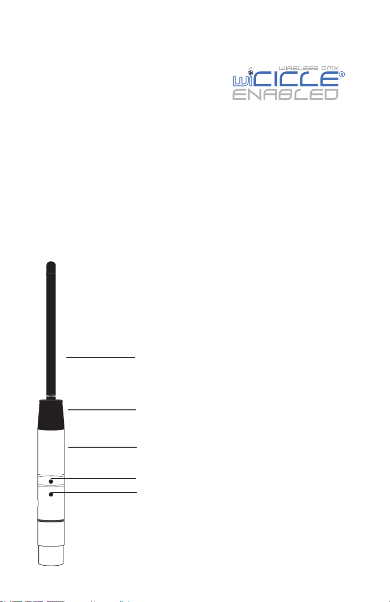
WE HAD THIS SPACE, SO WE FIGURED WE’D DRAW
YOU A PICTURE:
Antenna Housing & 1/2-wave
Antenna
Antenna ferrule & articulation
joint
Stainless Steel Housing
Recessed Selector Button
Status LED
3-Pin XLR Connector
(Male on transmitter, Female
on receiver model)
HotBox Manual Rev. A © 2013 Blizzard Lighting, LLC
Page 8
Page 9

Each wiCICLE® acts as both a transmitter and a receiver, depending on whether
a DMX source is applied to the integral XLR connector. This is an extremely
powerful feature of the system, however, it also requires 1 piece of due dilligence, and that is the removal of extraneous DMX signals from your lighting rig
BEFORE proceeding.
SO: BEFORE DOING ANYTHING ELSE, YOU SHOULD DISABLE ANY
BUILT-IN PROGRAMS IN THE FIXTURES YOU WISH TO CONNECT AND/
OR SET THEM AS SLAVES PRIOR TO RETURNING THEM TO DMX MODE
(IF APPLICABLE). Most xtures contain a built-in automatic, sound
active or custom program which is designed to operate with the xture
NOT connected to a DMX chain.
Some of these programs will automatically run unless the xture is set to slave
mode. These xtures typically sense DMX automatically and switch to DMX
mode upon receiving DMX signal (our Pucks do that!)
If you plug a wiCICLE® “receiver” into an autosensing xture set as a “master, “chances are good that the wiCICLE® “receiver” will begin transmitting the
master program. Most times, this is undesirable, and taking the two seconds to
switch these programs off will solve a lot of ails.
Got that done? Good! Then let’s proceed!
1. Plug the wiCICLE® Receiver into the “DMX IN” connector of the xture and
verify it is receiving power (the STATUS LED should illuminate.)
2. Connect the AC/DC adaptor to the the wiCICLE® Transmitter and verify it is
receiving power (the STATUS LED should illuminate.)
3. Press the RECESSED SELECTOR BUTTON on the Transmitter to select the
operating channel group. (The system will store this setting for future use)
The 7-Color Status LED will change color to indicate the current channel group:
· GROUP 1: RED
· GROUP 2: GREEN
· GROUP 3: YELLOW
· GROUP 4: BLUE
· GROUP 5: VIOLET
· GROUP 6: CYAN
NOTE: “GROUP” number
also corresponds to the
“GROUP” setting on our
LightCaster™ wireless DMX
Transceiver.
· GROUP 7: WHITE
4. Follow the same procedure on the Receiver to select the channel group.
5. Once both the transmitter and receiver(s) are both set to the same channel group, connect the transmitter to the DMX controller or the DMX out of a
xture on your DMX chain.
6. Once a DMX signal is provided to the transmitter, the status LED will blink
RED slowly until communication is established with the receiver. The status
LED on the receiver(s) will ash GREEN slowly until communication is estab-
lished.
7. Once the clearest channel is auto-selected, the status LEDs will blink quickly
on both the transmitter and receiver. NOTE: The color of the LED DURING
operation does not indicate channel group, instead it indicates whether the
unit is transmitting or receiving. That’s It!
HotBox Manual Rev. A © 2013 Blizzard Lighting, LLC
Page 9
Page 10
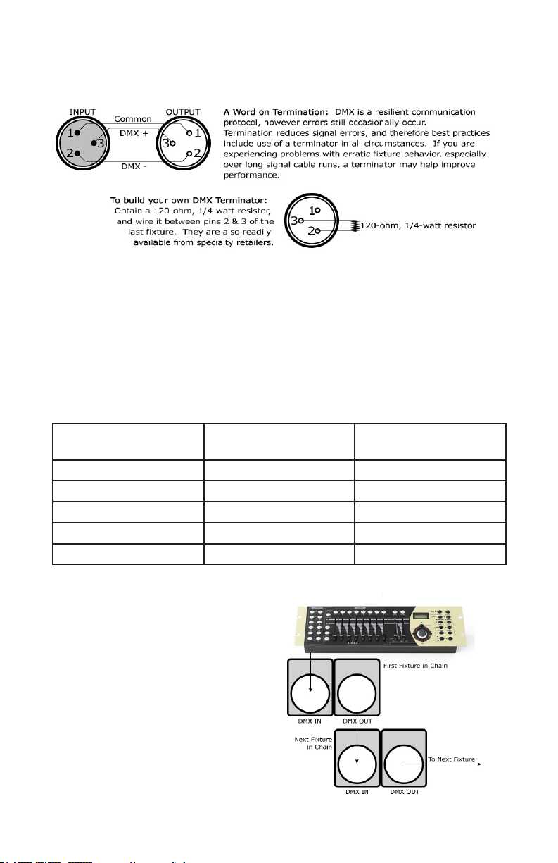
Cable Connectors
Cables must have a male XLR connector on one end and a female XLR
connector on the other end. (Duh!)
CAUTION: Do not allow contact between the common and the x-
ture’s chassis ground. Grounding the common can cause a ground
loop, and your xture may perform erratically. Test cables with an
ohm meter to verify correct polarity and to make sure the pins are not
grounded or shorted to the shield or each other.
3-Pin??? 5-Pin??? Huh?!?
If you use a controller with a 5 pin DMX output connector, you will need to use a 5 pin to 3 pin adapter.
They are widely available over the internet and from specialty retailers If you’d like to build your own, the
chart below details a proper cable conversion:
Conductor 3-Pin Female
(Output)
5-Pin Male
(Input)
Ground/Shield Pin 1 Pin 1
DMX Data (-) Pin 2 Pin 2
DMX Data (+) Pin 3 Pin 3
Not Used. No Connection. No Connection.
Not Used. No Connection. No Connection.
Take It To The Next Level: Setting Up DMX Control
Step 1: Connect the male connector of the
DMX cable to the female connector (output)
on the controller.
Step 2: Connect the female connector of the
DMX cable to the rst xture’s male connector (input). Note: It doesn’t matter which
xture address is the rst one connected.
We recommend connecting the xtures in
terms of their proximity to the controller,
rather than connecting the lowest xture
number rst, and so on.
Step 3: Connect other xtures in the chain
from output to input as above. Place a DMX
terminator on the output of the nal xture
to ensure best communication.
HotBox Manual Rev. A © 2013 Blizzard Lighting, LLC
Page 10
Page 11
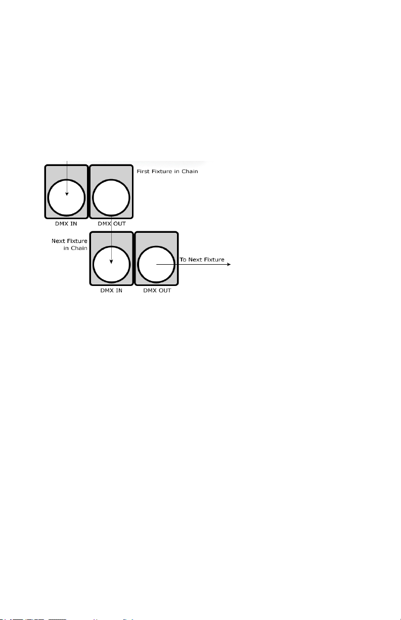
Fixture Linking (Master/Slave Mode)
1. Connect the (male) 3 pin connector side of the
DMX cable to the output (female) 3 pin connector of
the rst xture.
2. Connect the end of the cable coming from the
rst xture which will have a (female) 3 pin connector to the input connector of the next xture con-
sisting of a (male) 3 pin connector. Then, proceed
to connect from the output as stated above to the
input of the following xture and so on.
A quick note: Often,
the setup for MasterSlave and Standalone
operation requires that
the rst xture in the
chain be initialized for
this purpose via either
settings in the control
panel or DIP-switches.
Secondarily, the xtures
that follow may also require a slave setting.
Check the “Operating Adjustments” section in this manual for com-
plete instructions for this type of setup and conguration.
Mounting & Rigging
This xture may be mounted in any SAFE position provided there is
enough room for ventilation.
It is important never to obstruct the fan or vents pathway. Mount the
xture using a suitable “C” or “O” type clamp. The clamp should be
rated to hold at least 10x the xture’s weight to ensure structural sta-
bility. Do not mount to surfaces with unknown strength, and ensure
properly “rated” rigging is used when mounting xutres overhead.
Adjust the angle of the xture by loosening both knobs and tilting the
xture. After nding the desired position, retighten both knobs.
• When selecting installation location, take into consideration lamp
replacement access (if applicable) and routine maintenance.
• Safety cables MUST ALWAYS be used.
• Never mount in places where the xture will be exposed to rain,
high humidity, extreme temperature changes or restricted ventilation.
HotBox Manual Rev. A © 2013 Blizzard Lighting, LLC
Page 11
Page 12
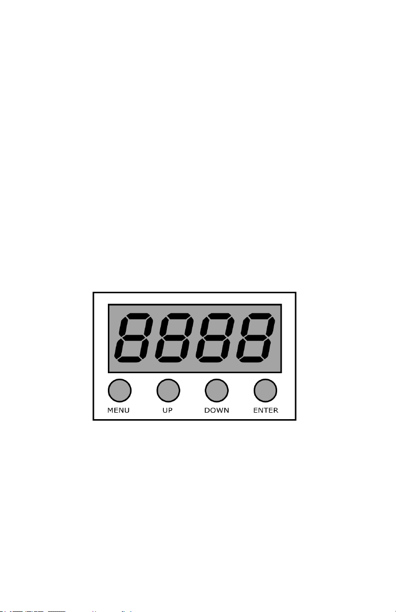
4. OPERATING ADJUSTMENTS
The Control Panel
All the goodies and different modes possible with the HotBox™ LED are
accessed by using the control panel on the rear of the xture. There
are 4 control buttons below the LED display which allow you to navigate through the various control panel menus.
<MENU>
Is used to navigate to the previous higher-level menu item.
<UP>
Scrolls through menu items and numbers in ascending order.
<DOWN>
Scrolls through menu items and numbers in descending order.
<ENTER>
Is used to select and conrm/store the current selection.
The Control Panel LED Display shows the menu items you select from
the menu map on page #11. When a menu function is selected, the
display will show immediately the rst available option for the selected
menu function. To select a menu item, press <ENTER>.
Press the <MENU> button repeatedly until you reach the desired
menu function. Use the <UP> and <DOWN> buttons to navigate the
menu options. Press the <ENTER> button to select the menu function
currently displayed, or to enable a menu option. To return to the previous option or menu without changing the value, press the
<MENU> button.
HotBox Manual Rev. A © 2013 Blizzard Lighting, LLC
Page 12
Page 13
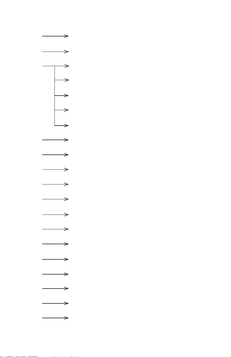
Control Panel Menu Structure
Addr d001 - d512 To choose the DMX address
SLAU SL.AU To run the xture in slave mode
CHnd 9CH 9 channel DMX mode
8CH 8 channel DMX mode
5CH 5 channel DMX mode
4CH 4 channel DMX mode
3CH 3 channel DMX mode
SP -- SP00 -SP15 Speed adjustments (0-15)
Pr -- Pr00 -Pr30 Built-in programs (0-30)
ASC - AC00 -AC15 Auto mode (0-15)
FAdE FA00 -FA15 Fade settings (0-15)
FLAS FL00 -FL15 Flash / strobe speed (0-15)
rL -- r.000 - r.255 Red dimmer (0% <--> 100%)
GL -- G.000 - G.255 Green dimmer (0% <--> 100%)
bL -- b.000 - b.255 Blue dimmer (0% <--> 100%)
UL -- U.000 - U.255 White dimmer (0% <--> 100%)
SouA So.uA Sound active mode
LED on - oFF Display menu on/off
nodE nod0-nod4 Dimming mode (0-4)
UErn UE2.0 Software version
HotBox Manual Rev. A © 2013 Blizzard Lighting, LLC
Page 13
Page 14

DMX Mode
Allows the unit to be controlled by any universal DMX controller.
1.) The default mode for the xture is DMX, which appears as d001 on the LED Readout. To
select a different DMX address, using the <MENU> button, select Addr,then hit <ENTER>.
Use the <UP/DOWN> buttons to select the correct address, then hit <ENTER> to conrm.
Setting the DMX Channel Mode:
1.) To select a DMX channel mode, press the <MENU> button, then use the <UP> or
<DOWN> buttons until the display reads Chnd and press the <MENU> button. Then use
the <UP> or <DOWN> buttons until the display reaches your desired channel mode. Press
the <MENU> button to conrm.
Stand-Alone, Master/Slave, Sound Active Modes:
Allows a single or Master/Slaved units to run factory installed programs at user selectable speeds.
1.) To set the xture in Flash/Fade mode, select FLAS or FAdE. To conrm, press the
<ENTER> button.
2.) Now, you can adjust the ash settings from FL00-FL15 or the fade settings from
FA00-FA15. Then press the <ENTER> button to conrm.
3.) To use the xture in automatic mode, select ASC-, and press the <ENTER> button. Then
use the <UP/DOWN> to choose from AS00-AS15, then press the <ENTER> button to
conrm.
4.) Adjust the speed of the chase as above using SP15 (slowest) to SP00 (fastest) then
press the <ENTER> button to conrm.
5.) To set the xture as a slave unit, select SLAU, and hit <ENTER>. The unit will display a
ashing SL.AU to indicate it is in slave mode.
Sound Active Mode:
1.) To use sound active mode, select SouA, then press the <ENTER> button to conrm.
Standalone (Program) Mode:
Allows a single unit to display a variety of colors and programs without a DMX controller.
1.) To set the xture in manual mode, select Pr--.
To conrm, press the <ENTER> button.
2.) Now, select the program by using the <UP> and <DOWN> buttons to select Pr00-
Pr15. To conrm, press the <ENTER> button.
Manual Color Adjustment:
Allows the user to adjust the color balance of the xture. These settings are global, they will effect all
modes.
1.) Use the <MENU> and <UP/DOWN> button to select rL-- (Red Level), GL-- (Green
Level), bL-- (Blue Level) or UL-- (White Level), then hit <ENTER>.
2.) Using the <UP/DOWN> buttons, select the maximum level for each color between x000-
x255 (000=off), then hit <ENTER> to conrm.
HotBox Manual Rev. A © 2013 Blizzard Lighting, LLC
Page 14
Page 15
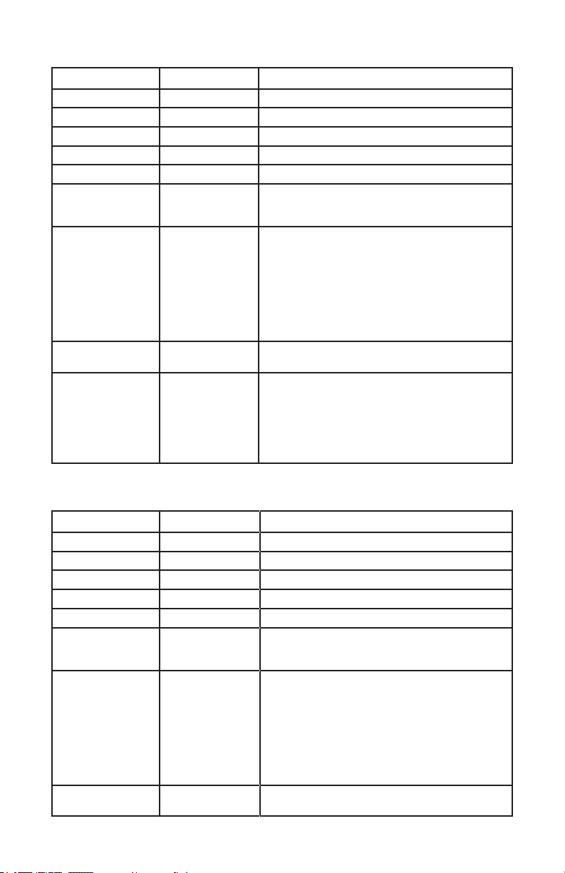
DMX Values In-Depth (9-Channel Mode)
Channel Value What It Does
1 000 <--> 255 Dimmer (0% <--> 100%)
2 000 <--> 255 Red Intensity (0% <--> 100%)
3 000 <--> 255 Green Intensity (0% <--> 100%)
4 000 <--> 255 Blue Intensity (0% <--> 100%)
5 000 <--> 255 White Intensity (0% <--> 100%)
6
000 <--> 014
015 <--> 255
7
000 <--> 031
032 <--> 063
064 <--> 095
096 <--> 127
128 <--> 159
160 <--> 191
192 <--> 223
224 <--> 255
8
0 <--> 255
9
000 <--> 005
006 <--> 055
056 <--> 105
106 <--> 155
156 <--> 205
206 <--> 255
Strobe
Dimming
Strobe (Slow <--> Fast)
Fade, Color Change, Sound Active
No Function
Fade In (Ch. 8 Controls Speed)
Fade Out (Ch. 8 Controls Speed)
Fade In / Fade Out (Ch. 8 Controls Speed)
Multicolor Fade (Ch. 8 Controls Speed)
Fade In / Fade Out, Auto Run
Color Jump (Ch. 8 Controls Speed)
Sound Active, Multicolor (Ch. 8 Controls Speed)
Fade Speed
Fade Speed (Slow <--> Fast)
32-Bit Dimmer
As set in the control menu display
Mode 0 = 8-bit, 256 dimming steps
Mode 1 = 32-bit, 0-25% intensity range
Mode 2 = 32-bit, 0-50% intensity range
Mode 3 = 32-bit, 0-75% intensity range
Mode 4 = 32-bit, full intensity dimming
DMX Values In-Depth (8-Channel Mode)
Channel Value What It Does
1 000 <--> 255 Dimmer (0% <--> 100%)
2 000 <--> 255 Red Intensity (0% <--> 100%)
3 000 <--> 255 Green Intensity (0% <--> 100%)
4 000 <--> 255 Blue Intensity (0% <--> 100%)
5 000 <--> 255 White Intensity (0% <--> 100%)
6
000 <--> 014
000 <--> 255
7
000 <--> 031
032 <--> 063
064 <--> 095
096 <--> 127
128 <--> 159
160 <--> 191
192 <--> 223
224 <--> 255
8
0 <--> 255
HotBox Manual Rev. A © 2013 Blizzard Lighting, LLC
Strobe
Strobe Off
Strobe (Slow <--> Fast)
Fade, Color Change, Sound Active
No Function
Fade In (Ch. 8 Controls Speed)
Fade Out (Ch. 8 Controls Speed)
Fade In / Fade Out (Ch. 8 Controls Speed)
Multicolor Fade (Ch. 8 Controls Speed)
Fade In / Fade Out, Auto Run
Color Jump (Ch. 8 Controls Speed)
Sound Active, Multicolor (Ch. 8 Controls Speed)
Fade Speed
Fade Speed (Slow <--> Fast)
Page 15
Page 16
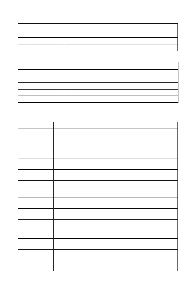
DMX Values In-Depth (HSV Mode)
Ch. Value What It Does
1 000 <--> 255 Hue
2 000 <--> 255 Saturation
3 000 <--> 255 Value
DMX Values In-Depth (4/5-Channel Mode)
Ch. Value What It Does (5 Ch.) What It Does (4 Ch.)
1 000 <--> 255 Dimmer (0% <--> 100%) Red Intensity
2 000 <--> 255 Red Intensity Green Intensity
3 000 <--> 255 Green Intensity Blue Intensity
4 000 <--> 255 Blue Intensity White Intensity
5 000 <--> 255 White Intensity ---
Troubleshooting
Symptom Solution
Fixture Auto-Shut
Off
Beam is Dim Check optical system and clean excess dust/grime. Also ensure that
No Light Output Check to ensure xture is operating under correct mode, IE sound
Chase Speed Too
Fast/Slow
No Power Check fuse, AC cord and circuit for malfunction.
Blown Fuse Check AC cord and circuit for damage, verify that moving parts are
Slow Movement Verify that 220V/110V switch is in the correct position, if applicable.
No Response to
Audio
Fixture Not
Responding /
Responding Erraticly
Intermittent
Lamp
Remote Doesn’t
Work
Fixture Moving
On Its Own
Check the fan in the xture. If it is stopped or moving slower than
normal, the unit may have shut itself off due to high heat. This is to
protect the xture from overheating. Clear the fan of obstructions,
or return the unit for service.
the 220V/110V switch is in the correct position, if applicable.
active/auto/DMX/Etc., if applicable.
Check to ensure proper setup of speed adjustment.
not restricted and that unit’s ventilation is not obstructed
Also check that speed channels are set appropriately.
Verify that the xture is in “Sound Active” mode.
Adjust Audio Sensitivity, If Applicable.
Make sure all connectors are seated properly and securely.
Use Only DMX Cables and/or check cables for defects
Install a Terminator.
Reset xture(s).
Check lamp for properly installation.
Relamp, lamp may have reached end of life.
Verify remote control cable is installed properly and securely.
Verify remote is correct type (CA-9 or other as applicable.)
Verify proper mode of operation. Is the xture in “Auto” mode?
If your problem persists or isn’t listed contact [email protected].
HotBox Manual Rev. A © 2013 Blizzard Lighting, LLC
Page 16
Page 17

5. APPENDIX
A Quick Lesson On DMX
DMX (aka DMX-512) was created in 1986 by the United States Institute for Theatre
Technology (USITT) as a standardized method for connecting lighting consoles to lighting
dimmer modules. It was revised in 1990 and again in 2000 to allow more exibility. The
Entertainment Services and Technology Association (ESTA) has since assumed control over
the DMX512 standard. It has also been approved and recognized for ANSI standard clas-
sication.
DMX covers (and is an abbreviation for) Digital MultipleXed signals. It is the most common
communications standard used by lighting and related stage equipment.
DMX provides up to 512 control “channels” per data link. Each of these channels was originally intended to control lamp dimmer levels. You can think of it as 512 faders on a lighting
console, connected to 512 light bulbs. Each slider’s position is sent over the data link as an
8-bit number having a value between 0 and 255. The value 0 corresponds to the light bulb
being completely off while 255 corresponds to the light bulb being fully on.
DMX data is transmitted at 250,000 bits per second using the RS-485 transmission standard over two wires. As with microphone cables, a grounded cable shield is used to prevent
interference with other signals.
There are ve pins on a DMX connector: a wire for ground (cable shield), two wires for
“Primary” communication which goes from a DMX source to a DMX receiver, and two wires
for a “Secondary” communication which goes from a DMX receiver back to a DMX source.
Generally, the “Secondary” channel is not used so data ows only from sources to receivers. Hence, most of us are most familiar with DMX-512 as being employer over typical
3-pin “mic cables,” although this does not conform to the dened standard.
DMX is connected using a daisy-chain conguration where the source connects to the input
of the rst device, the output of the rst device connects to the input of the next device,
and so on. The standard allows for up to 32 devices on a single DMX link.
Each receiving device typically has a means for setting the “starting channel number” that
it will respond to. For example, if two 6-channel xtures are used, the rst xture might
be set to start at channel 1 so it would respond to DMX channels 1 through 6, and the next
xture would be set to start at channel 7 so it would respond to channels 7 through 12.
The greatest strength of the DMX communications protocol is that it is very simple and
robust. It involves transmitting a reset condition (indicating the start of a new “packet”),
a start code, and up to 512 bytes of data. Data packets are transmitted continuously. As
soon as one packet is nished, another can begin with no delay if desired (usually another
follows within 1 ms). If nothing is changing (i.e. no lamp levels change) the same data will
be sent out over and over again. This is a great feature of DMX -- if for some reason the
data is not interpreted the rst time around, it will be re-sent shortly.
Not all 512 channels need to be output per packet, and in fact, it is very uncommon to nd
all 512 used. The fewer channels are used, the higher the “refresh” rate. It is possible to
get DMX refreshes at around 1000 times per second if only 24 channels are being transmitted. If all 512 channels are being transmitted, the refresh rate is around 44 times per
second.
In summary, since its design and evolution in the 1980’s DMX has become the standard
for lighting control. It is exible, robust, and scalable, and its ability to control everything
from dimmer packs to moving lights to foggers to lasers makes it an indispensable tool for
any lighting designer or lighting performer.
HotBox Manual Rev. A © 2013 Blizzard Lighting, LLC
Page 17
Page 18

Keeping Your HotBox™ As Good As New
The xture you’ve received is a rugged, tough piece of pro lighting equipment, and as long as you take care of it, it will take care of you. That said, like
anything, you’ll need to take care of it if you want it to operate as designed.
You should absolutely keep the xture clean, especially if you are using it in an
environment with a lot of dust, fog, haze, wild animals, wild teenagers or spilled
drinks.
Cleaning the optics routinely with a suitable glass cleaner will greatly improve
the quality of light output. Keeping the fans free of dust and debris will keep
the xture running cool and prevent damage from overheating.
In transit, keep the xtures in cases. You wouldn’t throw a prized guitar,
drumset, or other piece of expensive gear into a gear trailer without a case,
and similarly, you shouldn’t even think about doing it with your shiny new light
xtures.
Common sense and taking care of your xtures will be the single biggest thing
you can do to keep them running at peak performance and let you worry about
designing a great light show, putting on a great concert, or maximizing your client’s satisfaction and “wow factor.” That’s what it’s all about, after all!
Returns (Gasp!)
We’ve taken a lot of precautions to make sure you never even have to worry
about sending a defective unit back, or sending a unit in for service. But, like
any complex piece of equipment designed and built by humans, once in a while,
something doesn’t go as planned. If you nd yourself with a xture that isn’t
behaving like a good little xture should, you’ll need to obtain a Return Authori-
zation (RA).
Don’t worry, this is easy. Just send an email to [email protected],
and we’ll issue you an RA. Then, you’ll need to send the unit to us using a
trackable, pre-paid freight method. We suggest using USPS Priority or UPS.
Make sure you carefully pack the xture for transit, and whenever possible, use
the original box & packing for shipping.
When returning your xture for service, be sure to include the following:
1.) Your contact information (Name, Address, Phone Number, Email address).
2.) The RA# issued to you
3.) A brief description of the problem/symptoms.
We will, at our discretion, repair or replace the xture. Please remember that
any shipping damage which occurs in transit to us is the customer’s responsibility, so pack it well!
Shipping Issues
Damage incurred in shipping is the responsibility of the shipper, and
must be reported to the carrier immediately upon receipt of the items.
Claims must be made within seven (7) days of receipt.
HotBox Manual Rev. A © 2013 Blizzard Lighting, LLC
Page 18
Page 19
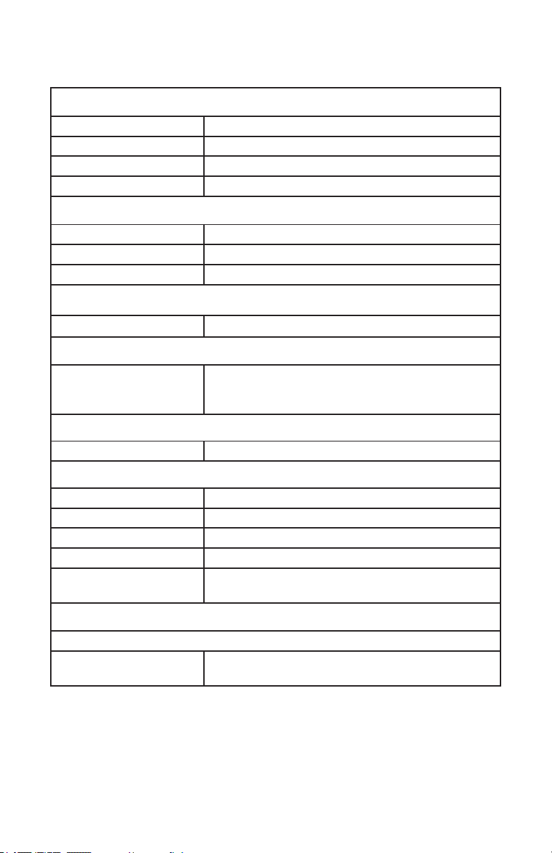
Tech Specs!
Weight & Dimensions
Length 4 inches (102 mm)
Width 5 inches (127 mm)
Height 5 inches (127 mm)
Weight 3.5 lbs (1.60 kg)
Power
Operating Voltage 100-250VAC, 40-60 Hertz
Fuse 2A 250V
Power Consumption 47W
Light Source
LED 7x 10W 4-in-1 LEDs 100,000 hours.
Optical
Beam Angle 25 degree optics standard
26 degree beam
30 degree eld
Thermal
Max. Operating Temp. 104 degrees F (40 degrees C) ambient
Control
Protocol USITT DMX-512
DMX Channels 3 / 4 / 5 / 8 / 9
Input 3-pin XLR Male
Output 3-pin XLR Female
Standalone, Master/Slave, Sound Active, Color
Other Operating Modes
Preset
Random Fact
Polar Bears Are Left Handed
2-year limited warranty, does not cover mal-
Warranty
DISCLAIMER:
The power connector tted to the xture and xture cord are designed for compatibility
with products manufactured by Neutrik AG, Neutrik USA and their related entities, howev-
er they are not manufactured by, afliated with or endorsed by Neutrik AG, Neutrik USA,
or any related entity. Neutrik® and powerCON® are registered trademarks of Neutrik AG.
HotBox Manual Rev. A © 2013 Blizzard Lighting, LLC
function caused by damage to LED’s.
Page 19
Page 20
Enjoy your product!
Our sincerest thanks for your purchase!
--The team @ Blizzard Lighting
 Loading...