

Blitz FIA-18 Assembly And Operating Manual
Assembly and operating instructions
Assembly and Operating Manual

Assembly and Operating Manual
2
Dear customer,
Congratulations on your choice of a
factory-assembled model aircraft from BLITZ RC
Hummingbird range and thank you for placing
your trust in us.
Very little preparation work is required to get this
model ready to fly. To operate your new model
safely, i t is important that you read through all of the
instructions and safety information included with
your model before you fly it for the first time.
The illustrations in this manual show the Blue
Angels version of the model with factory applied
decals.
The power system
The model is powered by a brushless outrunner
motor and ducted fan, both of which are
factory-installed on the Ready-To-Fly version.
The motor is connected to the electronic speed
controller which is factory calibrated on the
Ready-To-Fly version. All that is required is to
charge the Li-Po battery, following the safety
instructions, and connect the battery to the
electronic speed controller.
Proceed to power down in reverse order:
disconnect the battery from the electronic speed
controller first, and then switch off the transmitter.
The radio control system
To fly the F/A 18 – Blue Angels you will need a
radio control system with at least four channels.
2.4GHz radios systems are recommended, similar
to the unit included with our Ready-To-Fly version.
The servos for the ailerons and the elevators are
factory-installed.
The power for the receiver is drawn from the
electronic speed controller’s integral BEC system.
The electronic speed controller is located inside of
the fuselage, in front of the ducted fan.
To check the model’s operating systems, first set
the control surface servos to neutral by setting the
trims to center and leaving throttle stick and tri m t o
the lowest position.
When you wish to fly the model, always make sure
the transmitter is “ON”. Move the throttle stick to
the “OFF” position as well. Then connect the flight
battery to the electronic speed controller.
Gluing joints with suitable adhesives
Foam safe epoxy is recommended and available
from most reputable model retail shops.
Trial-fit all parts “dry” before applying glue.
Follow the recommended curing time suggested by
the glue manufacturer. Allow the glue to fully cure
(harden) to the point where the joint can be placed
under stress.
Kit contents
Fuselage, with motor, electronic speed controller
and servos
Clear canopy and cockpit
Left / right wing panels with ailerons
Left / right tail plane panels with elevators and
vertical stabilizer
Accessories
1 x Li-Po battery, 3s 950mAh 20C
1 x 20A Brushless ESC (Electronic Speed Controller)
Parts List
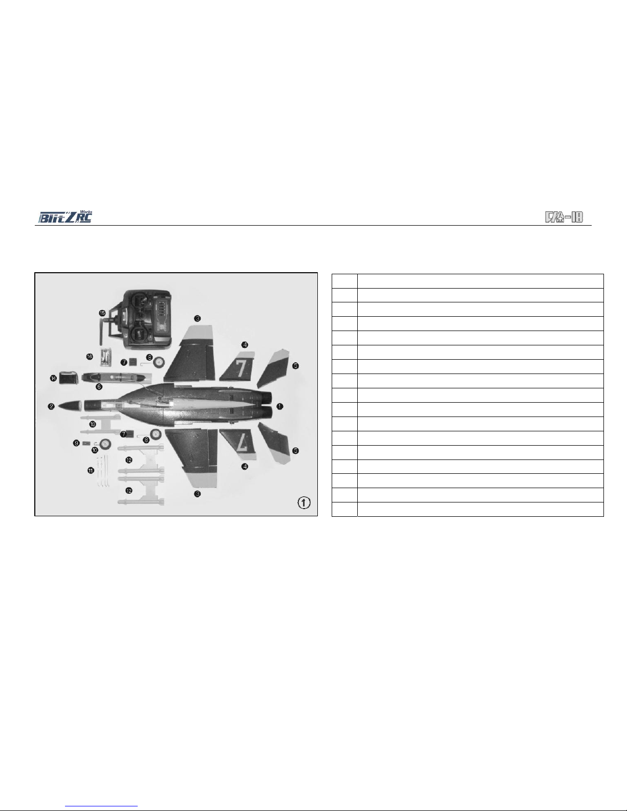
NO. Description
1 Fuselage
2 Nose Cone
3 Wing Set – One Left (and one Right) Wing Panel
4 Tail Set - One Left (and one Right) Horizontal Stabilizer
5 Tail Set - One Vertical Stabilizer
6 Cockpit Canopy
7 One Left (and one Right) Main Landing Gear Fixed Plate
8 Two Main Wheels
9 Front Wheel Fixed Plate
10 Front Wheel
11 Push Rods Set
12 Big Missiles
13 Small Missiles
14 950mAh 11.1 Volt 20C Li-Po Battery
15 Radio Control Transmitter (we highly recommend 2.4 GHz system)
16 Balance Charger
Assembly and Operating Manual
3
Fig. 1 Open the box and check all the parts.
Parts Illustration
Assembly and Operating Manual
4
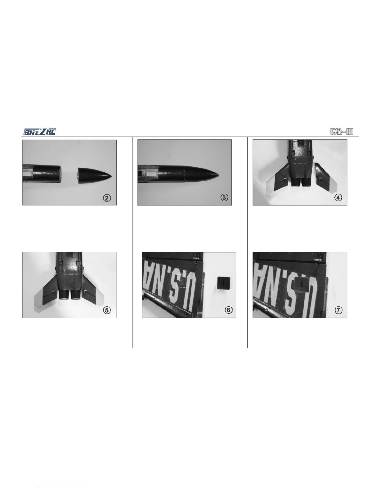
Fig. 2 - Locate the fuselage and nose cone
Fig. 5 - Remove any excess glue and hold in
position until the glue sets. The photo shows the
finished view.
Fig. 3 - Glue the nose to the front of fuselage (glue
not included).
Fig. 6 - Glue the main wheel fixed plate to the slot
on one half of the main wing panel (the white mark
shown the slot).
Fig. 4 - Glue the horizontal stabilizers to the slots at
the rear of the fuselage (glue not included).
Fig. 7 - Make sure there is no glue in the slot for the
main wheel. Remove any excess glue on the wing
and plate surface.
 Loading...