


THE CALDERA
USERS’
INSTALLATION
OPERATION &
MAINTENANCE
Page 1
THE CALDERA
DIRECT VENTED TOP OR Rear
VENT GAS Room Heater
For use with natural gas or propane
WARNING: If the information in this manual
is not followed exactly, fire or explosion may
result causing property damage, personal
injury or loss of life.
— Do not store or use gasoline or other
flammable
vapors and liquids in the vicinity of this or
any other appliance.
— WHAT TO DO IF YOU SMELL GAS
· Do not try to light any appliance.
· Do not touch any electrical switch; do
not use any phone in your building.
· Immediately call your gas supplier from
a neighbor’s phone. Follow the gas
supplier’s instructions.
· If you cannot reach your gas supplier,
call the fire department.
— Installation and service must be
performed by a qualified installer, service
agency or the gas supplier.
This appliance may be installed in an
aftermarket permanently located,
manufactured (mobile) home, where not
prohibited by local codes.
This appliance is only for use with the type
of gas indicated on the rating plate. This
appliance is not convertible for use with
other gases, unless a certified kit is used.
INSTALLER: PLEASE LEAVE THIS MANUAL WITH
THE CUSTOMER
CUSTOMER: PLEASE KEEP MANUAL FOR FU-
TURE REFERENCE
Pour la version française de nos manuels S.V.P. vous référez à notre site web : www.blazeking.com
Version 1.09 SIT
Nov 2010

Page 2
THE CALDERA
CONTENTS
Introduction 4
General Information 5
Appliance Dimensions 6
Installation Clearances 7 - 9
Installation Instructions - Appliance 10 - 12
Assembly Instructions - Log Set 13-14
Installation Instructions - Venting 15-23
Rigid Venting Parts List 24-26
Intermittent Pilot & Valve Information 27-28
Page
Wiring Diagram 29
Lighting Instructions 30-31
Handheld Thermostat Remote Control - Operation instructions 32-36
Maintenance 37-39
Servicing 40-41
Fuel Conversion 42-43
Allowed Termination Location 44
Troubleshooting 45-46
Top / Rear Vent Conversion 47
Fan Kit Installation 48-49
Replacement Parts 50-51
Warranty 52
Notes & Service History 53
MANUFACTURED IN CANADA BY:
Valley Comfort Systems Inc.
1290 Commercial Way
Penticton, BC
V2A 3H5
Ph# 1-250-493-7444
Email vcsales@vip.net
Patents Pending
MANUFACTURED IN USA BY:
Blaze King Industries
146 A Street
Walla Walla, WA.
99362
Ph# 1-509-522-2730
Email bki@bmi.net

Page 3
THE CALDERA
Note: A copy of the certification label is provided here for your review. Due to constant up-grades it
is possible that the information shown here may not coincide with the label as attached to the unit.
In the event of a discrepancy between the labels, the label on the unit is considered as the correct

Page 4
THE CALDERA
INTRODUCTION
Thank you for purchasing the Caldera Zero Clearance Fireplace Gas Heater.
The Caldera is one of the most advanced direct vented zero clearance gas heaters on
the market. It is designed using the latest technology and manufactured to the highest
quality.
Some of the many features are:
Electronic Valve Intermittent pilot & remote capability.
Heater Classification It is classified as a heating appliance. Therefore, it can be
operated continuously for zone heating.
High Efficiency It has high efficiency; therefore, it is less expensive to operate.
Adjustable Flame The flame aesthetics and heat output can be adjusted to suit the
owner’s moods and heating needs.
Solid Construction It is constructed mainly heavy gauge steel for long life and
durability.
Please read the manual carefully prior to installation and operation of the
appliance. Proper installation, operation and maintenance of the appliance will
provide you with many years of enjoyment.
CAUTION
Due to high temperatures, the appliance should be located out of traffic and
away from furniture and draperies.
Children and adults should be alerted to the hazards of high surface
temperature and stay away to avoid burns or clothing ignition.
Young children should be carefully supervised when they are in the same room
as the appliance.
Clothing or other flammable material should not be placed on or near the
appliance.
Any parts removed or opened for servicing of the appliance must be properly
replaced prior to operating the appliance.
The appliance must be inspected before use and at least annually by a qualified
service person. More frequent cleaning maybe required due to excessive lint
from carpeting, bedding material, etc. It is imperative that the control
compartments, burners and circulating air passageways for the appliance be
kept clean.
Venting terminals shall not be recessed into a wall or siding.
This gas appliance must not be connected to a chimney flue serving a separate
solid fuel burning appliance.

Page 5
THE CALDERA
GENERAL INFORMATION
APPLIANCE CERTIFICATION
This appliance is tested and certified to the following US and Canadian gas appliance standards.
- ANSI Z21.88-2007 / CSA 2.33-2007 Vented Gas Fireplace Heaters,
- CAN/CGA-2.17-M91 Gas-Fired Appliance fo Use at High Altitudes
- CSA P.4.1-02 Testing Method for Measuring Annual Fireplace Efficiency
Please contact Valley Comfort or Blaze King, if you have any questions regarding the certification of this
appliance.
INSTALLATION CODES
This appliance must be installed by a qualified gas appliance installer. The installation must conform with
the local codes or, in the absence of local codes, with the current National Fuel Gas Code, ANSI Z223.1/
NFPA 54, in the US or Installation Code, CSA-B149.1, in Canada. Electrical connections and grounding
must be in accordance with local codes, if any, if not, follow the current CAN/CSA C22.1 in Canada and
ANSI/NFPA 70 in the US. This appliance is certified for installation in a bedroom or a bedsitting room.
This appliance is only for use with the type of gas indicated on the rating plate and may be installed in an
aftermarket, permanently located, manufactured (mobile) home where not prohibited by local codes. See
owner’s manual for details. This appliance is not convertible for use with other gases, unless a certified kit
is used. This appliance must be installed in accordance with the current Standard CAN/CSA Z240 1411,
Mobile Housing, or with the Manufactured Home Construction and Safety Standard Title 24 CFR, Part
3280, or when such a standard is not applicable, ANSI/NCSBCS A225.1/NFPA 501A, Manufactured
Home Installations Standard.
Only for direct discharge without duct connection. This appliance must be direct vented using listed and
approved Simpson Dura-Vent, Selkirk, Security or American Metal Products vent components.
SPECIFICATIONS
Natural Gas (NG) Propane (LP)
Manifold Pressure
Min. Supply Pressure for
Purpose of Input Adjustment
Orifice Size
Nominal Input Rating
Altitude
Primary Air Opening
3.5 in. W.C. (0.9 kpa) 10.0 in. W.C. (2.5kpa)
5.0 in. W.C. (1.24 kPa) 12.0 in. W.C. (3.0 kPa)
#35 DMS #51 DMS
35,000 - 24,000 BTU/hr
(10.26 – 7.04 kW)
0 - 4,500 ft. (0 - 1372 m) 0 - 4,500 ft. (0 - 1372 m)
closed 100% open
35000 - 26,000 BTU/hr
(10.26 – 7.26 kW)
HIGH ALTITUDE INSTALLATION
When installing this appliance beyond 4500 ft. (1372 m) above sea level, the appliance must be properly
de-rated and installed according to local codes, in the absence of local codes, with the current National
Fuel Gas Code, ANSI Z223.1/ NFPA 54, in the US or Installation Code, CSA-B149.1, in Canada.

THE CALDERA
Page 6
APPLIANCE DIMENSIONS
Figure 1

THE CALDERA
Page 7
INSTALLATION CLEARANCES
Figure 2
C
A - Internal Ceiling Height min. 60" (1524 mm)
B - Internal Framing min. 45" (1143 mm)
C - Sidewall Clearance min. 6" (152 mm)
D - Unexposed Back & Sides min. 2" (51 mm)
Mantle - See Chart
Vertical Vent - 1" (25 mm) to outside surface
Horizontal Vent - 1" (25 mm) to outside bottom & side surface, 2" (51 mm) to outside top surface
Can be installed on a combustible surface.
D

THE CALDERA
Figure 3A
Minimum framing
dimensions
Page 8
INSTALLATION CLEARANCES
Figure 3B
Mantle Clearances to
Combustibles
Mantle Height
from Floor (B)
50" (1270 mm) 12" (300 mm)
49" (1245 mm) 11-5/16" (287 mm)
48" (1219 mm) 10-9/16" (268 mm)
47" (1194 mm) 9-7/8" (251 mm)
46" (1168 mm) 9-3/16" (233 mm)
45" (1143 mm) 8-7/16" (214 mm)
44" (1118 mm) 7-3/4" (197 mm)
43" (1092 mm) 7-1/16" (179 mm)
42" (1067 mm) 6-5/16" (160 mm)
41" (1041 mm) 5-5/8" (143 mm)
40" 1016 mm) 4-15/16" (125 mm)
39" (991 mm) 4-3/16" 106 mm)
38" (965 mm) 3-1/2" (89 mm)
37" (940 mm) 2-13/16" (71 mm)
36" (914 mm) 2-1/16" (52 mm)
Mantle Depth (A)
Max.
35" (889 mm) 1-3/8" (35 mm)
34" (864 mm) 11/16" (17 mm)

THE CALDERA
Page 9
INSTALLATION CLEARANCES
Figure 3C Minimum Framing Dimensions
Figure 3D Minimum Framing Dimensions
THE CALDERA
INSTALLATION INSTRUCTIONS
Page 10
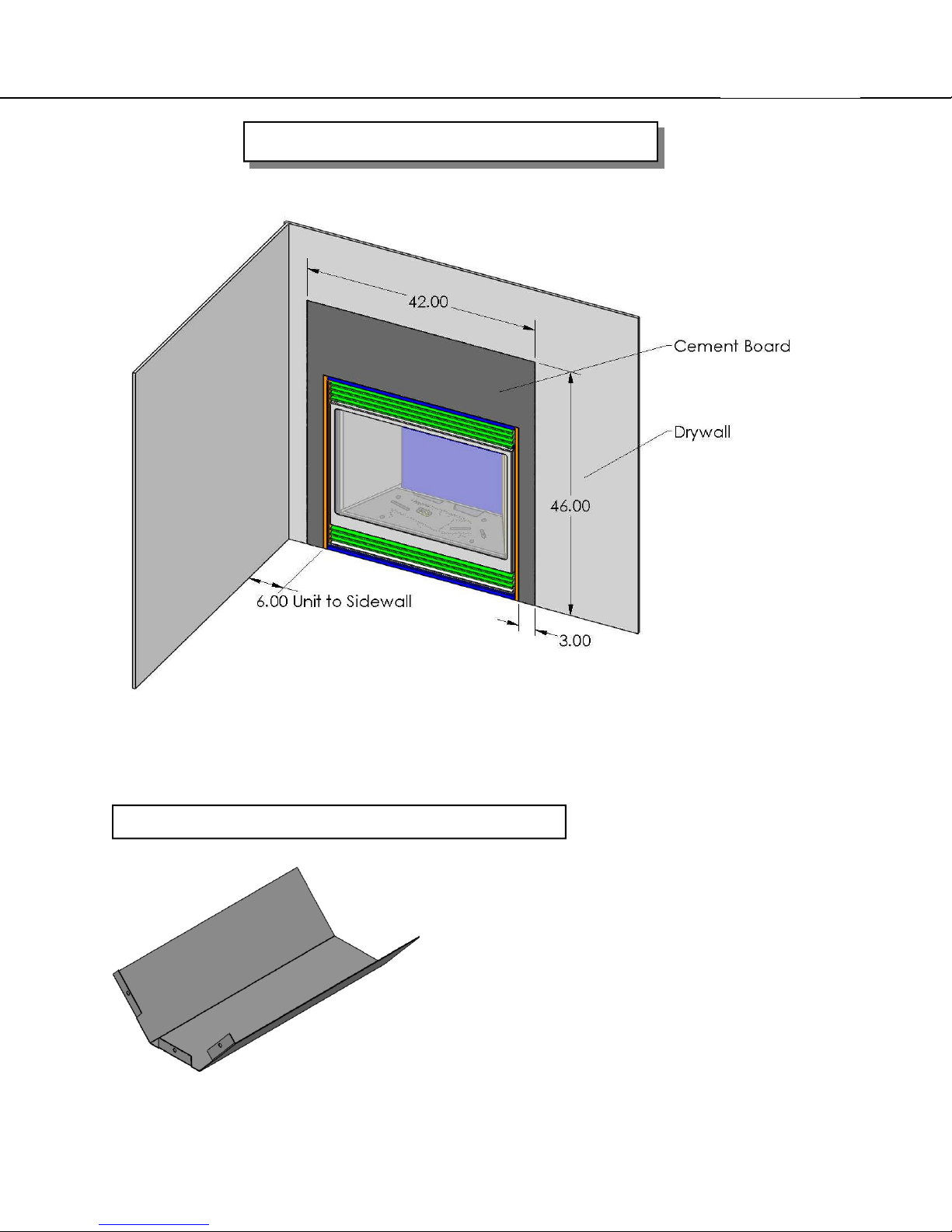
Figure 3C Cement Board Dimensions
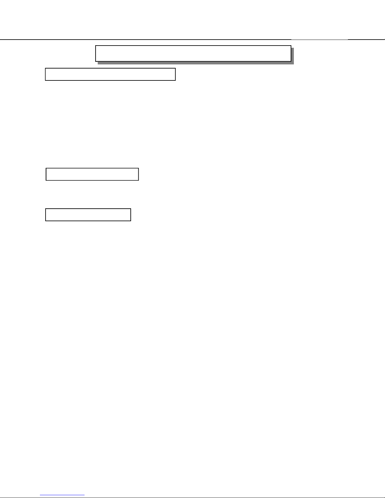
INSTALL VERTICAL HEAT SHIELD (Top Vent Only)
The heat shield which comes with the appliance,
needs to be mounted vertically on top of the appliance. The three holes line up with the ones on top
of the appliance, in front of the flue collar.
Use three screws to mount the heat shield.
IMPORTANT:When the heat shield is not
installed, fire may result, causing property
damage, personal injury or loss of life.
(For top vent only)

Page 11
THE CALDERA
INSTALLATION INSTRUCTIONS Cont...
PRECAUTIONS
This appliance must be installed by a qualified gas installer and the installation
conform to applicable installation codes.
This appliance needs fresh air for safe operation and must be installed so there are
provisions for adequate ventilation air. Provide adequate clearance around air openings of
the appliance. Never obstruct front openings.
Provide adequate clearances for proper operation and servicing of the appliance.
This appliance must be properly connected to a venting system.
This appliance must NOT be connected to a chimneyflue serving a solid-fuel appliance.
LOCATING GAS FIREPLACE
The venting system of this appliance must be installed in a location that is free of plumbing,
electrical wiring and heating or air conditioning ducts. Select a location that is accessible for
venting. See the ALLOWABLE TERMINATION LOCATIONS - page 45, in this manual.
ANCHORING UNIT
After determining the location, the appliance needs to be anchored to framing and floor.
Attach to the floor with two screws through the holes in the bottom of the appliance (see Figure
3D) The holes are located behind the bottom louver, one on the left, one on the right.
Attach to the frame by the
standoffs on top of the
unit (See Figure 3D)
The standoffs can be
adjusted by loosening the
screws on top of the
appliance
Figure 3D
Page 12
THE CALDERA
INSTALLATION INSTRUCTIONS Cont...
VENT TERMINATION LOCATION
1.Establish a suitable vent termination location. (See ALLOWABLE TERMINATION
LOCATIONS - page 45)
2.In heavy snowfall areas make sure vent termination is located where it can not be blocked by
snowfall or snow from snow removal equipment.
3.Locate vent termination away from plants, bushes or any other object on or near the vent
termination that will interfere or obstruct the air flow around it.
4.DO NOT recess vent termination into walls, sidings or planters.
5.Vent terminations located below 7 ft (2130 mm) from grade level or anywhere that it is a burn
hazard to the public, such as patios and balconies, must be protected with an approved
termination cage.
POWER CONNECTION
You will need to have an electrician supply 120 volts to the area of the fireplace and
terminate in the junction box inside the unit.
GAS CONNECTIONS
Have your gas supplier or a qualified gas fitter run a gas supply line to the gas fireplace. For
your convenience the appliance has a shut-off valve and flex line installed, check with your local
installation codes if this is to code.
There is an access hole situated under the burner for easier access to the gas valve connection.
(Left side under burner, triangular shaped)
CAUTION: The appliance and its individual shutoff valve must be disconnected from the gas
supply piping system during any pressure-testing of that system at test pressures
in excess of 1/2 psig (3.5 kPa). The appliance must be isolated from the gas
supply piping system by closing its individual manual shutoff valve during any
pressure-testing of the gas supply piping system at test pressures equal to or less
than 1/2 psig (3.5 kPa). Failure to do so will damage the appliance’s gas valve.
Such damage is not covered by the manufacturer’s warranty.
Check for proper gas supply pressure by loosening the set screw on supply pressure tap on the
gas valve with a small flat tip screw driver and placing a test gauge on the tap.
The minimum permissible gas supply pressure is 5 in. w.c. (1.24 kPa) for natural gas and 12.0
in. w.c. (3.00 kPa) for propane. Maximum gas supply pressure should never exceed 14.0 in.
w.c. (3.48 kPa) or 1/2 psi. for both natural gas and propane.
BE SURE TO TIGHTEN THE PRESSURE TAP SET SCREW AFTER CHECKING THE
PRESSURE.
Before connecting the appliance to the gas supply line, double check that the appliance you
have purchased is designed for the gas type you are using. The gas type markings are located
on the certification label and also on the appliance’s gas valve.
Adequate clearance for proper installation and checking of the gas connections must be
provided. All gas connections must be checked for gas leaks.

Page 13
THE CALDERA
ASSEMBLY INSTRUCTIONS
GLASS DOOR REMOVAL
Removing the Glass Door
- Remove the top & bottom louvers.
- Unhook the door latches found on the bottom of the firebox.
- Carefully lift and remove the door.
- Place the door at a safe location where it cannot be scratched or damaged.
- If the glass door is damaged, it must be replaced with another glass door certified with this
appliance only.
- Replacement glass doors are available through your Blaze King dealer (See Replacement Parts
page 51)
Replacing the Glass Door
- Check the condition of the glass and the gasket before installing door.
- Carefully hook the door onto the tabs on the top of the firebox.
- Connect the door latches, at the bottom of the door, and close latches.
Install the top & bottom louvers.
If the glass has been damaged contact your dealer and replace the glass and gasket with a new
glass and gasket provided by your dealer.
WARNING:
- Do not attempt to remove the glass door when the appliance is hot.
- Do not abuse the glass door.
- Do not strike or slam the glass.
- Do not operate this appliance with cracked or broken glass.
- Do not use any substitute materials.

THE CALDERA
ASSEMBLY INSTRUCTIONS Cont...
PLACEMENT OF LOGS AND TWIGS
Page 14
Step 1: Place rear log in notch on left
side and on log pin on right side.
Step 3: Place left log on left front
burner and rear log as shown.
Step 2: Place left and right twigs on log pins
as shown.
Step 4: Place center twig on rear log
and front of burner as shown.
WARNING : Do not place the logs in any other configuration than the one shown. Fire,
explosion or excessive carbon monoxide (CO) may result, causing property
damage, personal injury or loss of life.
Step 5: Place right log on rear log
and front of burner as shown.

Page 15
THE CALDERA
INSTALLATION INSTRUCTIONS Cont...
VENTING - Rear Vent
This appliance will not function without being connected to a proper venting system.
This appliance uses 4" x 6-5/8" rigid vent, when used with Simpson Duravent adapter
0923AR (included with appliance). This unit can be used with Selkirk (Direct-Temp),
Security Chimneys or Simpson Duravent 4" x 6-5/8" venting, but for the snorkel only the
American Metal can be used Read the manufacturer’s installation instructions before
installing the venting system.
Typical Installation (for rear vented appliance)
- 7” to 24”(max) horizontal vent pipe exiting wall behind the appliance and a 36"
American Metal snorkel.
- One 45oelbow is allowed for corner installations (24” total length max).
36" Snorkel
(Adj.) Pipe length
24" Max.
Wall Thimble
923AR adaptor

Page 16
THE CALDERA
INSTALLATION INSTRUCTIONS Cont...
VENTING - Top Vent
This appliance will not function without being connected to a proper venting system.
This appliance uses 4" x 6-5/8" rigid vent, when used with Simpson Duravent adapter
0923AR (included with appliance). This unit can be used with Selkirk (Direct-Temp),
Security Chimneys or Simpson Duravent 4" x 6-5/8" venting. Read the manufacturer’s
installation instructions before installing the venting system.
Typical Installation
- 9”(min) vertical vent pipe on top of the appliance,
- One 90oelbow, and up to 24” (max) horizontal run to the outside.
Other installations
- Up to 4 - 90oelbows, or equivalent, maximum.
- Minimum 2’ (610mm) straight length between bends.
- The total vertical height up to 30’ (9.1 m) maximum.
- Use vent restrictor over 20’ vertical height (See page 18)
- The total horizontal run up to 16’ (4.9 m) maximum (Note: 4’ (1.2m) minimum of
vertical height required if 16’ horizontal).
Note: Maximum vent lengths may be subject to local codes.
Vent Termination
Typical installation
X
Wall thimble
Z
Pipe Length A
Y
90 Elbow
9" Pipe Length
923AR Adaptor
X = Wall Thickness
Y = Front Fireplace to Wall
Z = Back Fireplace to Wall
Pipe Length A = X+Y-15 ½”
= X+Z- ½”
Examples:
X= Wall
thickness
4” 17 ½” 2 ½” 6”
5” 19 ½” 4 ½”
6” 18 ½” 3 ½” 9”
7” 17 ½” 2 ½”
8” Min.
9” Min.
10” Min.
Y Z
18 ½”
17 ½”
17”
Min.
3 ½”
Min.
2 ½”
Min.
2”
Length Pipe A
9”
9”
11” - 14 5/8”
ADJUSTABLE
11” - 14 5/8”
ADJUSTABLE
11” - 14 5/8”
ADJUSTABLE

Page 17
THE CALDERA
INSTALLATION INSTRUCTIONS Cont...
For best venting performance, here are some general venting rules:
1. Use only vent systems and components certified for use with this appliance
2. Maintain a minimum of 1” (26 mm) clearance to combustibles from the outside
surfaces of vertical vents and minimum of 1” (26 mm) sides and bottom, and 2” (51
mm) from top surfaces of horizontal vents. Always use a wall thimble when passing
through combustible construction.
3. Observe all local code restrictions, if any, regarding the installation of this type of gas
appliance.
4. Observe the vent height and length restrictions given in this manual.
5. Never slope horizontal vents downwards.
6. Maintain at least an upward slope of 1/4” (7 mm) for every 1 ft (305 mm) of
horizontal vent.
7. Terminate the vent with a termination certified for use with this appliance.
8. Support horizontal vent every 3 ft (915 mm) to prevent it from sagging.

THE CALDERA
INSTALLATION INSTRUCTIONS Cont...
VENTING CHART
Page 18
Example 1
V Value = 3A (12') + 1C (3') = 15'
H Value = 2B (4') =4'
V Value = Total length of all vertical sections in feet.
H Value = Total length of all horizontal sections in
feet.
Note:
for H & V values for 45º venting see Chart IV
elbows are not counted in H or V values
vent chart starts from the top of the unit

Page 19
THE CALDERA
INSTALLATION INSTRUCTIONS Cont...
VENT RESTRICTORS FOR TOP VENT INSTALLATIONS
All top vent installations above 20' (6.1 m) require the use of
60% restrictor.
The restrictor is installed in the exhaust of the appliance.
Vent Restrictors
Due to the extra flow produced by certain venting configurations vent restrictors must
be placed in the vent to maintain performance. When your installation requires a vent
restrictor you must remove the flue baffle and install the restrictor in the exhaust box as
shown below. The restrictor is fastened in with 2 screws represented by the dotted
line in the figure below. Once the vent restrictor has been installed the flue baffle must
then be re-installed.
Note: The unit must be cooled to room temperature before installing the restrictor.
Figure 4

Page 20
THE CALDERA
INSTALLATION INSTRUCTIONS Cont...
WARNING: A minimum clearance of 1” to combustibles must be maintained
on vertical pipe runs and 2” for horizontal pipe runs (sides and bottom 1”)
The rigid vent systems use twist lock connections. The adaptor attached to the unit
connects to the approved venting system. While you are assembling the pipe bear in mind the
best visual appearance. Seams should be aligned and hidden as much as possible. Make sure
you twist the mating section all the way to make a solid connection.
Note: As this system is a sealed system, a high temperature sealing compound must be
used to seal the metal to metal joint.
Apply a bead of high temperature sealant to both the 4”
exhaust and 6-5/8” intake section of the male pipe. The
female section of the pipe/fitting has four indentations
evenly spaced around the pipe. These indentations are
designed to slide over the male section of the pipe and
locate into the four entry slots of the male section of pipe.
Twist the female section clockwise a quarter turn to fully
lock the sections together.
High
Temperature
Sealant
(Mil-Pac / RTV)
Horizontal Wall Vent Terminations
The position of the horizontal vent termination must be positioned to meet all local building
codes (see termination chart on page 45).
Attach the correct length of vertical section pipe and an elbow fitting to the stove.
Mark the center line of the pipe facing the wall (allowing for a 1/4” rise per foot of horizontal
run). Example 10 ft of horizontal would require a rise of 2.5”.
NOTE: ALLOWING THE VENT PIPE TO SLOPE DOWN TOWARDS THE VENT
TERMINATION COULD CAUSE POOR COMBUSTION AND/OR HIGH TEMPERTURES
THAT MAY PRESENT A FIRE HAZARD. Mark a 10” x 10” square around the center mark
(inside dimensions).
Cut and frame the exterior wall to accept the wall penetration heat shield. Install the
penetration shield using wood screws. If the wall being penetrated is constructed of noncombustible material a 7” hole sufficient for the vent pipe, is acceptable.
Caution: When installing the termination on to vinyl siding, a vinyl siding kit must be
used. This prevents the termination from being recessed into the siding.
When the termination is to be attached to vinyl siding apply a bead of non-hardening mastic
around the outside edge to form a seal between the standoff and the termination cap. Attach
the termination cap to the exterior wall inserting four wood screws through the holes in the
corner of the vent termination. Complete the installation by applying a bead of mastic around
the outer edge of the vinyl standoff.
With the termination cap installed you can now connect the completed vent assembly by
sliding the unit back towards the wall and carefully inserting the pipe into the terminal. Before
the final connection is made slide on the decorative wall thimble. Secure the termination cap by
securing the termination straps to the pipe as close to the exterior wall as possible using sheet
metal screws. Ensure that the straps are hidden by the wall thimble cover. Apply decorative
trim if required.

Page 21
THE CALDERA
INSTALLATION INSTRUCTIONS Cont...
Vertical Installations
Always maintain the 1” clearance around the vent pipe (vertical), when passing through
ceilings, walls, roofs, enclosures, attic rafters or any combustible surfaces.
DO NOT PACK AIR SPACES WITH INSULATION.
Refer to the vent chart for maximum allowable vertical and horizontal installations.
When planning your installation determine if ceiling joists, roof rafters or other framing will
obstruct the vent system. You may have to use 45° elbows to navigate around any obstacles.
When passing through a flat ceiling install a Box/Wall thimble. Cut a 10” square hole and frame
as shown in the diagram opposite.
Ensure all pipe sections are fully twist locked.
NOTE: ALWAYS CHECK YOUR LOCAL CODES BEFORE INSTALLING VENTING.
NECESSARY CLEARANCES AND REQUIRMENTS MAY VARY FROM STATE TO STATE
(PROVINCE TO PROVINCE).

THE CALDERA
INSTALLATION INSTRUCTIONS Cont...
Page 22
Through Roof Framing
Maintain 10” opening relative to the pitch of
the roof.
10” square
Termination Above Roof
Consult local codes for minimum vent cap
height above the roof, vent must be a
minimum 2’ from any wall.
Use a suitable round or square support
through the roof. Ensure adequate heat
shield protection is provided.
To prevent water seepage install the
flashing with upper portion slid under the
roofing material and the lower portion over
the roofing material.
Note: Do not fasten down until the final
adjustments to the vent have been
made.

THE CALDERA
INSTALLATION INSTRUCTIONS Cont...
Typical vent Installation
Alternate 45° pipe
requiring strap
support
Page 23
High Wind Vertical
Termination Cap
Flashing
Figure 5
Wall Thimble or
Fire-Stop
Twist Lock
Joints

THE CALDERA
Page 24
SIMPSON DURAVENT DIRECTVENT PRO / GS SYSTEM PARTS LIST
Description Part # Old Part #
Description Part #
Horizontal Termination Kit - In Canada—Mandatory to add a wall thimble
Horizontal Termination Kit - In Canada—Mandatory to add a wall thimble. 971
(46DVA-KHC.)
Vertical Termination Kit 978
Vertical Termination Kit - 978
6” Pipe Length -Black 908B
6” Pipe Length -Black 46DVA-06B 908B
9” Pipe Length-Black 907B
6” Pipe Length –Galvanized 46DVA-06 908
12” Pipe Length-Black 906B
8,5” Black Extension (3”-7”) 46DVA-08AB -
12” Pipe Length-Galvanized 906
8,5” Galvanized Extension (3”-7”) 46DVA-08A -
24” Pipe Length-Black 904B
9” Pipe Length-Black 46DVA-09B 907B
24” Pipe Length-Galvanized 904
9” Pipe Length-Galvanized 46DVA-09 907
36” Pipe Length-Black 903B
12” Pipe Length-Black 46DVA-12B 906B
36” Pipe Length-Galvanized 903
12” Pipe Length-Galvanized 46DVA-12 906
48” Pipe Length-Black 902B
16” Black Extension (3”-14.5”) 46DVA-16AB -
48” Pipe Length-Galvanized 902
16” Galvanized Extension (3”-14.5”) 46DVA-16A -
11”- 14 5/8” Adjustable Pipe Length-Black 911B
24” Pipe Length-Black 46DVA-24B 904B
17”- 24” Adjustable Pipe Length-Black 917B
24” Pipe Length-Galvanized 46DVA-24 904
45° Elbow-Black 945B
36” Pipe Length-Black 46DVA-36B 903B
45° Elbow-Galvanized 945
36” Pipe Length-Galvanized 46DVA-36 903
45° Elbow-Swivel-Black 945BG
48” Pipe Length-Black 46DVA-48B 902B
45° Elbow-Swivel-Galvanized 945G
48” Pipe Length-Galvanized 46DVA-48 902
90° Elbow-Galvanized 990
11”- 14 5/8” Adjustable Pipe Length-Black - 911B
90° Elbow-Black 990B
17”- 24” Adjustable Pipe Length-Black - 917B
90° Elbow-Swivel-Galvanized 990G
45° Elbow-Black 46DVA-E45B 945B, 945BG
90° Elbow-Swivel-Black 990GB
45° Elbow-Galvanized 46DVA-E45 945, 945G
Vertical High Wind Termination Cap (must be used for all vertical terminations) 991
90° Elbow-Galvanized 46DVA-E90 990, 990G
Horizontal. DV Termination with 1” return 984GL
90° Elbow-Black 46DVA-E90B 990B, 990BG
Horizontal. Square Termination Cap 984
Vertical High Wind Termination Cap (must be used for all vertical termina-
Horizontal. Square High Wind Termination Cap 985
tions)
Horizontal. DV Termination with 1” return - 984GL
Snorkel-14” Rise Termination Cap 982
Horizontal. Square Termination Cap - 984
Wall Thimble Cover—Support Box 940
Horizontal. Square High Wind Termination Cap 46DVA-HC 985
Cathedral Ceiling Support Box 941
Horizontal Round Termination Cap 46DVA-HRCS -
Brass Trim fro Ceiling Support Box 3951
Sconce Termination Cap 46DVA-HSC -
Fire stop Spacer 963
Wall Thimble Cover—Support Box 46DVA-DC 940
Flashing 0/12-6/12 943
Cathedral Ceiling Support Box 46DVA-CS 941
Flashing 7/12-12/12 943S
Brass Trim fro Ceiling Support Box 3951
Storm Collar 953
Firestop Spacer 46DVA-FS 963
Vinyl Siding Standoff 950
Flashing 0/12-6/12 46DVA-F6 943
Wall Strap 988
Flashing 7/12-12/12 46DVA-F12 943S
Wall Pen Heat Shield (Wall Thimble) 942
Storm Collar 46DVA-SC 953
Vinyl Siding Standoff 46DVA-VSS 950
Wall Strap 46DVA-WS 988
Wall Pen Heat Shield (Wall Thimble) 46DVA-WT 942
SIMPSON DURAVENT GS SYSTEM PARTS LIST
46DVA-KHA 971
46 DVA-VCH 991

THE CALDERA
Page 25
SELKIRK PARTS LIST
PART NUMBER DESCRIPTION
4" x 65/8" LENGTHS
1604006 4DT- 6 DIRECT-TEMP 6" PIPE LENGTH
1604006B 4DT- 6B DIRECT-TEMP 6" PIPE LENGTH BLACK
1604009 4DT- 9 DIRECT-TEMP 9" PIPE LENGTH
1604009B 4DT- 9B DIRECT-TEMP 9" PIPE LENGTH BLACK
1604012 4DT-12 DIRECT-TEMP 12" PIPE LENGTH
1604012B 4DT-12B DIRECT-TEMP 12" PIPE LENGTH BLACK
1604018 4DT-18 DIRECT-TEMP 18" PIPE LENGTH
1604018B 4DT-18B DIRECT-TEMP 18" PIPE LENGTH BLACK
1604024 4DT-24 DIRECT-TEMP 24" PIPE LENGTH
1604024B 4DT-24B DIRECT-TEMP 24" PIPE LENGTH BLACK
1604036 4DT-36 DIRECT-TEMP 36" PIPE LENGTH
1604036B 4DT-36B DIRECT-TEMP 36" PIPE LENGTH BLACK
1604048 4DT-48 DIRECT-TEMP 48" PIPE LENGTH
1604048B 4DT-48B DIRECT-TEMP 48" PIPE LENGTH BLACK
1604082 4DT-AJ12 DIRECT-TEMP 12" ADJ PIPE LENGTH
1604082B 4DT-AJ12B DIRECT-TEMP 12" ADJ PIPE LENGTH BLACK
1604084 4DT-AJ14 DIRECT-TEMP TELESCOPE ADJ LENGTH
1604084B 4DT-AJ14B DIRECT-TEMP TELESCOPE ADJ LEN BLACK
4" x 65/8" FITTINGS
1604215 4DT-EL45 45 DEGREE ELBOW
1604215B 4DT-EL45B 45 DEGREE ELBOW BLACK
1604230 4DT-EL90S 90S DEGREE ELBOW
1604230B 4DT-EL90SB 90S DEGREE ELBOW BLACK
4" x 65/8" ACCESSORIES
1604460B 4DT-WTB WALL THIMBLE BLACK
1604500 4DT-FS FIRESTOP SPACER
1604502 4DT-TP TRIM PLATE BLACK
1604806 4DT-VS VINYL SIDING STANDOFF
4" x 65/8" SUPPORTS
1604400 4DT-CS CEILING SUPPORT
1604424 4DT-CCS CATHEDRAL SUPPORT BOX
1604430 4DT-WS/B WALL SUPPORT/BAND
1604435 4DT-OS OFFSET SUPPORT
4" x 65/8" TERMINATIONS
AND FLASHINGS
1604620 4DT-VKC VERTICAL TERMINATION KIT
1604621 4DT-HKA HORIZONTAL TERMINATION KIT "A"
1604622 4DT-HKB HORIZONTAL TERMINATION KIT "B"
1604802 4DT-VC HIGH WIND VERTICAL CAP
1604804 4DT-HC HIGH WIND HORIZONTAL CAP
1604810 4DT-SC STORM COLLAR
1604825 4DT-AF6 ADJ FLASH 0/12-06/12
1604830 4DT-AF12 ADJ FLASH 6/12-12/12

Page 26
THE CALDERA
AMERICAN METAL PRODUCTS COMPONENTS LIST
Description Part #
7” Pipe Length 4D7
12” Pipe Length 4D12
2’ Pipe Length 4D2
3’ Pipe Length 4D3
4’ Pipe Length 4D4
4” - 10” AdjustableLength 4D12A
45° Elbow 4D45L
90° Elbow 4D90L
Vertical Termination 4DVC
Horizontal Termination 4DHC
36” Snorkel 4D36S
Wall Thimble 4DWT
Wall Strap 4DWS
Fire stop Support Plate 4DFSP
Faceplate, Ceiling Support / Wall Thimble 4DFPB
Roof Support 4DRSB
Storm Collar 4DSC
Standard Flashing 4DF
Steep Pitch Flashing 4DF12
Attic Insulation Shield 4DAIS12
SECURITY VENTING COMPONENTS LIST
6” Pipe Length SV4L6
12” Pipe Length SV4L12
24” Pipe Length SV4L24
36” Pipe Length SV4L36
48” Pipe Length SV4L48
6” Adjustable Length SV4LA
12” Adjustable Length SV4LA12
45° Elbow SV4E45
90° Elbow SV4E90
Wall Band SV4BM
Insulated Attic Shield SV4RSA
Wall Shield SV4RSM
Fire stop SV4BF
Adjustable Roof Flashing 1/12 — 7/12 SV4FA
Horizontal Termination SV4CHC
Vertical Termination SV4CGV

THE CALDERA
INTERMITTENT PILOT & VALVEINTERMITTENT PILOT & VALVE
Page 27
SIT 885 Proflame Valve
Outlet pressure tap
Main valve
Connection
(red)
Inlet pressure tap
Stepper motor
Pilot Connection
(green)
Pilot Flame adjustment
Ground connection

THE CALDERA
INTERMITTENT PILOT & VALVE (cont’d)
Page 28
Optional Wall thermostat
(interrupt green wire)

Page 29
THE CALDERA
WIRING DIAGRAM
Caution: Label all wires prior to disconnection when servicing controls. Wiring errors
can cause improper and dangerous operation. Verify proper operation after servicing.
Figure 16

Page 30
#0361Se
THE CALDERA
LIGHTING INSTRUCTIONS - Intermittent Pilot
FORYOUR SAFETY, READ BEFORE LIGHTING
WARNING: If you do not follow these instructions exactly, a fire or explosion may
result causing property damage, personal injury or loss of life.
A. This appliance is equipped with an ignition device which automatically lights the pilot. Do not try to light the pilot by hand.
B. BEFORE LIGHTING smell all around the appliance area for gas. Be sure to smell next to the f loor because some gas
is heavier than air and will settle on the floor.
WHAT TO DO IF YOU SMELL GAS:
- Do not try to light any appliance.
- Do not touch any electric switch; do not use any phone in your building.
- Immediately call your gas supplier from a neighbor’s phone. Follow the gas supplier’s instructions.
- If you cannot reach your gas supplier, call the fire department.
C. Do not use this appliance if any part has been under water. Immediately call a qualified se rvice technician to inspect
the appliance and to replace any part of the control system and any gas control which has been under water.
LIGHTINGINSTRUCTIONS
1. Read the safety information above on this label.
STOP!
2. Set the thermostat to the lowest setting.
3. Turn off all electric power to the appliance.
4. Do not attempt to light the pilot by hand.
5. Wait five (5) minutes to clear out any gas. Then smell for gas, including near the floor. If you smell gas, STOP!
Follow “B” in the safety information above on this label. If you don’t smell gas, go to t he next step.
6. Turn on all electric power to the appliance.
7. You must now synchronize the remote with the Receiver/Battery Pack (for 1st time use)
Battery Pack (fig. 1 (Battery Pack is situated behind the Pedestal front or Louvers)) fol lowed by pressing the “ON” button
on the Remote.
8. Press the "ON" button on the Remote (fig. 2) or if not using the Remote turn the switch on the Battery Pack to the
"ON" position (see figure1 ).
9. If the appliance will not operate, follow the instructions "To Turn Off Gas ToAp pliance" and call your service technician
or gas supplier.
by pressing the PRG button on the
TO TURN GAS OFF TO APPLIANCE
1. Press the "OFF" button on the remote or if not using the remote turn the switch on the batt ery pack to the “OFF” position.
(See fig. 1)
2. Turn off all electric power to the appliance.
ON /OFF
FIG 1: RECEIVER / BATTERY PACK
FIG 2: REMOTE CONTROL

Page 31
THE CALDERA
OPERATION INSTRUCTIONS
LIGHTING INSTRUCTIONS
FOR YOUR SAFETY, READ BEFORE LIGHTING
INITIAL OPERATION
- Check that the appliance is properly vented and connected to the gas supply.
- Check the logs and twigs are properly placed.
- Check all external parts, such as grills, door and control cover are properly attached and fastened.
NOTE : When operated for the first few times, the appliance will emit some odor and fumes. This is
due to the evaporation of oils and solvents used in fabricating the appliance. Close off the
room to the rest of the house and open all windows. Keep the room well ventilated.

Page 32
THE CALDERA
HANDHELD THERMOSTAT REMOTE CONTROL-operation instructions
Fig. 3: Receiver body

Page 33
THE CALDERA
HANDHELD THERMOSTAT REMOTE CONTROL-operation instructions

Page 34
THE CALDERA
HANDHELD THERMOSTAT REMOTE CONTROL-operation instructions

Page 35
THE CALDERA
HANDHELD THERMOSTAT REMOTE CONTROL-operation instructions

Page 36
THE CALDERA
HANDHELD THERMOSTAT REMOTE CONTROL-operation instructions
Continuous Pilot
ON/OFF
Continuous pilot
The pilot on this unit will light automatically when
turning the unit on.
If a standing pilot is preferred (especially in cold
weather) , the pilot can be run continuously by
switching the continuous pilot switch to the ON
position. The switch is located behind the bottom
louver, above the Receiver / Battery pack.
Batteries under
this cover

Page 37
THE CALDERA
MAINTENANCE
CAUTION :Do not conduct maintenance on the appliance while it is operating or while it is still hot.
Make sure Remote switch on the Module is in OFF position (See figure 9 page 29) and turn
burner switch OFF. Turning the electric supply off will not prevent unexpected ignition !!
CLEANING THE APPLIANCE
The exterior surfaces and glass may be cleaned with a soft, non-abrasive cloth and water or a suitable,
mild, non-abrasive cleaner.
Regularly,
- Clean and remove any lint accumulations or debris from the grills and in any combustion and convection
air passage ways.
- Keep the appliance area free from combustible materials, such as paper, wood, clothing, gasoline and
flammable solids, liquids and vapors.
- Check for unusual noise, odor and operation of the appliance.
- Check the vent terminal for any damage, or obstruction by plants or debris accumulation.
- Visually check the height and color of the burner and pilot flames.
MAIN FLAME
INTERMITTENT PILOT FLAME:
Figure 12
Figure 14
Once a Year,
- Remove the glass door and clean the inside of the glass with a soft,
non-abrasive cloth and water or a suitable, mild, non-abrasive cleaner.
- Carefully remove the logs and gently brush off any loose carbon
deposits. This job is best done outside the house, wearing a dust
mask.The logs are very fragile, take care not to break them. After
cleaning, the logs must be replaced as per the instructions in this
manual.
Once a Year have a qualified service technician,
- Completely inspect the appliance and the venting system.
- Clean and remove any lint accumulations or debris in the firebox, on the burners, on the pilot,
at the primary air opening, on the convection air blower and in any combustion and convection
air passage ways.
- Check the safety shut-off system of the gas valve.
WARNING : All parts removed or disturbed must be properly replaced after maintenance.
Service and repair must be conducted by a qualified service person. If these
instructions are not followed, a fire or explosion may result, causing property
damage, personal injury or loss of life.
VERIFY PROPER OPERATION AFTER SERVICING.

Page 38
THE CALDERA
MAINTENANCE
PLATING:
1. The plating requires little maintenance and needs only to be cleaned with a soft damp cloth. Do not
use any abrasive cleaning materials.
2. Avoid fingerprints on gold. Wipe off fingerprints before firing.
DOOR :
Check the gasket to see that it is still forming a seal. Replace gasket if there is any sign of wear.
VIEWING GLASS REPLACEMENT:
This appliance is supplied with high temperature 5mm high temperature ceramic glass that will easily
withstand the heat your unit was designed to produce. In the event the glass breaks, contact your dealer
or BLAZE KING to arrange for your glass to be replaced / repaired (see page 12).
IMPORTANT - GLASS CLEANING - WHITE MINERAL DEPOSITS
One of the byproducts of the combustion process in a gas appliance, is a mineral which can show up as
a white film on the ceramic glass of the viewing door. The composition of the deposit varies widely from
various locations and also from time to time in the same location. You may have the problem for a time
and then not see it for many months when it will reappear in your area. It seems this is associated with
the varying sulfur content of the gas. We have discussed this problem with ceramic glass manufacturers
and they cannot give us a definitive answer to this problem. Dealers have tried various cleaning products
with varying results. The following recommendations will not guarantee results in your particular case.
Ensure the stove is completely cooled before you change the bulb. Make sure switch on the
Battery pack / Receiver is in OFF position.
Turning the electric supply off will not prevent unexpected ignition !!
1. Clean the glass regularly as soon as you notice the buildup (white film). If the film is left for a long
period of time build up will bake on. It is then much harder, if not impossible, to remove.
2. NEVER use an abrasive cleaner on the ceramic glass. Any abrasion of the surface has the
immediate effect of lessening the strength of the glass. An emulsion type cleaner is recommended.
3. Use a soft damp cloth to apply the cleaner. Dry the glass with a soft, dry, preferably cotton cloth.
Most paper towels and synthetic materials are abrasive to ceramic glass and should be avoided.
4. Our dealers have had good results from the products listed below. We can not however guarantee
the results of these products.
a) BRASSO b) POLISH PLUS by KEL KEM
c) COOK TOP CLEAN CREME by ELCO d) WHITE OFF by RUTLAND
NOTE: This is a problem beyond Blaze King’s control and is
not covered under warranty.
NOTICE: COLD WEATHER OPERATION
When using any gas appliance (LPG or NAT Gas) water is a byproduct of the combustion process.
Under normal conditions this moisture is expelled through the vent into the atmosphere and does not
cause any harm. In extreme cold weather the vapor may condense and freeze on any exposed surface
it comes into contact with. This can cause a problem by restricting or blocking the vent, particularly with
direct vent wall terminations as the exhaust is only a few inches away from the outside wall surface.
What happens to the moisture after it leaves the vent cannot be controlled by the manufacturer. To
extend the vent further out from the wall can sometimes but not always be an advantage. Extending the
vent out from the wall may present other design problems such as ice falling from the eaves above. It is
the homeowners responsibility to ensure that there is not an excessive build-up of ice on the termination.
CAUTION: WHEN OPERATING YOUR APPLIANCE DURING COLD WEATHER YOU MUST
FREQUENTLY CHECK THE EXHAUST CAP FOR EXCESSIVE ICE BUILD UP.
If the appliance begins to operate abnormally—Poor flame pattern, shutting down, etc…, this could be
an indication of ice build up.

Page 39
THE CALDERA
MAINTENANCE
REPLACING HALOGEN LIGHT BULB (OPTIONAL SHROUDS ONLY)
The light is situated at the inside of the shroud. Replace with the light bulb specified in the replacement
parts list on page 49. To replace the light bulb follow these instructions:
Ensure the stove is completely cooled before you change the bulb. Make sure switch on the
Battery pack / Receiver is in OFF position.
Turning the electric supply off will not prevent unexpected ignition !!
1. Turn off electric supply
2. Open the right door (arched shroud) or take off shroud (rectangular shroud)
3. Using a screw driver, remove the cover plate (rectangular shroud only)
4. Remove old bulb by pulling straight out, to insert new bulb, push straight in.
(Avoid touching glass with bare hands, hold bulb with clean cloth or tissue)
5. Re-install and turn power back on.
Page 40
THE CALDERA
SERVICING
SERVICING UNDER WARRANTY
Before servicing, read the terms and conditions of the Blaze King warranty at the back of this manual.
Contact the Blaze King authorized dealer which you purchased the appliance from and provide him with
details of the problem and the installation information which the installer filled out at the back of the
manual.
WARNING: Servicing of this appliance must be conducted by a qualified service technician.
Improper servicing, adjustment or alteration of this appliance may cause property
damage, personal injury or loss of life. All servicing should be conducted with the
appliance cold.
ADJUSTING PRIMARY AIR
- Remove the lower louver (open doors/remove optional front first if used) to gain access to the shutter.
- Loosen the primary air shutter screw (above burner rocker switch)
(caution, make sure unit is not hot as burns may result).
- Sliding the shutter lever right increases aeration while sliding the lever to the left decreases
aeration.
- Tighten screw.
CHANGING MAIN BURNER ORIFICE
- Remove the glass door, logs and firebox liner panels.
- Remove the burner. Remove the screws holding the aeration box to the firebox floor and lift it out.
- Use a 1/2” wrench to unscrew the orifice
- Change the orifice. Do not over tighten.
- Replace all parts in reverse order and properly set the primary air shutter according to the specifications.
- Check for leaks.
CHECKING INLET AND OUTLET GAS PRESSURE
- The pressure test taps are located on the valve.
- The taps are located in the front.
- Loosen the set screw inside the tap with a 1/8” wide flat screw driver.
- Connect a 1/4” rubber tube to the tap and a pressure gauge.
- Be sure to tighten the set screw inside the tap after you are finish taking pressure readings.

Page 41
THE CALDERA
SERVICING Cont...
GAS COMPONENTS ASSEMBLY
The gas component assembly can be taken out of the appliance for easier servicing.
Replacing Gas Component Assembly
- Disconnect electricity to the appliance.
- Shut off the gas supply to the appliance and disconnect the gas line at the valve
- Remove the glass door, logs and burner.
- Disconnect the wires from the module-box
- Remove the screws holding the gas component assembly to the appliance firebox bottom.
- Gently lift the assembly out and remove through the front.
- Replacing the assembly is the reverse of the above instructions.
* Check the tray sealing gasket. Replace if damaged.
THE CALDERA
FUEL CONVERSION
“WARNING”
This conversion kit shall be installed by a qualified service
agency in accordance with the manufacturer’s instructions
and all applicable codes and requirements of the authority
having jurisdiction. If the information in these instructions is
not followed exactly, a fire, explosion or production of
carbon monoxide may result causing property damage,
personal injury or loss of life. The qualified service agency is
responsible for the proper installation of this kit. The
installation is not proper and complete until the operation
of the converted appliance is checked as specified in the
manufacturer’s instructions supplied with the kit.
Conversion Kit Contents
This conversion kit contains the following parts:
1) For LPG # 51 orifice and LPG Stepper motor
2) For NG # 35 orifice and NG stepper motor
Page 42
To convert from NG to LPG or reverse, follow the next steps.
- Replace burner orifices,
- Replace stepper motor (see next page).
- Convert pilot fuel (see instructions below)
How to convert Pilot fuel:
Use a 7/16” wrench to loosen the pilot hood
Push the little tab in and the little tab with hole should pop out.
The hole stamp tab (LP) out is used for Propane
The stamped tab (NA) out is for Natural Gas
Re-tighten the pilot hood.
Fill out the fuel conversion label on the appliance (inside side doors)
All valves have been pre-set and certified for installation at elevations from 0 – 4500 feet (1 – 1372m)
above sea level.
High Elevations
When installing this unit at higher elevations, it is necessary to decrease the input rating by replacing
the existing burner orifice with a smaller size for installations over 2000 feet (608 m). The appliances
input should be reduced 4% for each additional 1000 feet (305 m) above sea level. For the USA, derate the unit from sea level according to the gas installation code.
Altitude Natural Gas
0 – 4,500 ft (0 – 1372 m) 35 51
4,500 – 6,500 ft (1372 – 1981 m) 36 52
6,500 – 8,000 ft (1981 – 2438 m) 37 53
Orifice Size
Propane
Orifice Size

THE CALDERA
Page 43
FUEL CONVERSION

THE CALDERA
ALLOWABLE TERMINATION LOCATIONS
Figure 19
Page 44
____________________________________________________________________________________________________
Canadian Installations
A= Clearance above grade, veranda *min. 12”(30mm) *min. 12”(30 mm)
porch, deck or balcony
____________________________________________________________________________________________________
B= Clearance to window or door *min. 12”(30 mm) *min. 12”(30 mm)
that may be opened
_______________________________________________________________________________________________
C= Clearance to permanently closed *min. 12”(30 mm) *min. 12”(30 mm)
window
____________________________________________________________________________________________________
D= Vertical clearance to ventilated *min. 20-1/2” (521 mm) *min. 20-1/2” (521 mm)
soffit located above the terminal within from center of termination from center of termination
a horizontal distance of 2’ (61 cm) from
the centerline of the terminal
1
US Installations
2
____________________________________________________________________________
E= Clearance to unventilated soffit *min. 20-1/2” (521 mm) *min. 20-1/2” (521 mm)
_________________________________________________________________________________________________
F=Clearance to outsidecorner *min. 10”(250 cm) *min. 10” (250 cm)
____________________________________________________________________________________________________
G=Clearance to insidecorner *min. 12-1/2" (318 mm) *min. 12-1/2" (318mm)
____________________________________________________________________________________________________
H= Clearance to each side of centerline 3’ (91cm) within a height15’ (4.5m) *
extended above meter/regulatorassembly above the meter/regulatorassembly
____________________________________________________________________________________________________
I= Clearance to service regulator vent outlet 3’ (91cm) *
____________________________________________________________________________________________________
J= Clearance to no mechanical air supply inlet 12” (30cm) 9” (23cm)
to building or the combustion air inlet to any
other appliance
____________________________________________________________________________________________________
K= Clearance to a mechanical air supply inlet 6’ (1.83 m) 3’ (91 cm) above if within 10’ (3m)
____________________________________________________________________________________________________
L= Clearance above paved sidewalk or paved 7’ (2.13 m)† *
driveway located on public property
____________________________________________________________________________________________________
M = Clearance under veranda, porch, deck or 12” (30 cm)‡ *
balcony
____________________________________________________________________________________________________
1
In accordance with the current CSA B149.1, NaturalGas and Propane Installation Code
2
In accordance with the current ANSI Z223.1/NFPA 54, National Fuel Gas Code
† A vent shall notterminate directly above a sidewalk or paved driveway that is located between two single family dwellings and
serves both dwellings.
‡ Permitted only if veranda, porch, deck or balcony is fully open on aminimum of two sides beneath the floor.
* For clearances not specified in ANSI Z223.1/NFPA54 or CSA B149.1, one of the following shall be indicated:
a) A minimum clearance value determined by testing in accordance with section 2.23.7, or ;
b) A reference to the following footnote: “Clearance in accordance with local installation codes andthe requirements of the gas
supplier”
from center of termination from center of termination
from center of termination from center of termination
from center of termination from center of termination
horizontally

Page 45
THE CALDERA
TROUBLESHOOTING
Please check to make sure the instructions are followed exactly before attempting
trouble shooting of the appliance.
WARNING: Troubleshooting and servicing of gas and electrical devices of the
appliance should only be conducted by a qualified service technician.
The pilot will not stay lit. 1) Confirm that the Spark electrode and sense electrode wires are
properly connected to the DFC board (See page 27 for terminal locations)
2) Confirm that the Pilot burner is properly grounded to the DFC board
and stove chassis.
3) Check the power source or the battery pack connections and
condition of batteries.
If the main burner does not
come ON when the manual
switch or remote control is
turned ON.
Pilot will not light. 1. When lighting the appliance for the first time after installation or after
1) Confirm that the pilot sparks and lights.
2) Confirm that the Spark electrode and sense electrode wires are
properly connected to the DFC board (See page 27 for terminal locations)
3) If using the remote control check the condition of the batteries.
4) Check if there is gas supply to the appliance
servicing, there is air in the gas line. It takes a while for all the air to
purge out of the pilot before gas can reach the pilot and ignite.
Remove the glass door and try lighting the pilot many times to purge
the air.
2. Check to make sure the gas supply to the appliance is turned on and
there is adequate gas supply pressure to the appliance.
3. Check for sparks between the spark electrode and the pilot head
when the unit is turned on. If there are no sparks,
a. Check for broken or poor connection from the sparker to the
electrode.
b. Check for the spark shorting or arcing at other locations.
c. Check for defective sparker.
d. Check for defective spark electrode.
e. Check the power source or the battery pack connections and condi-
tion of batteries.

THE CALDERA
SYMPTOM ACTION
Page 46
TROUBLESHOOTING Cont...
The main burner shuts off
when the appliance is warm.
Sooty deposits on the glass
door.
Sharp blue flames with flames
lifting off the burner at the
ends.
Convection blower does not
turn on.
1. This may be the normal operation of a wall thermostat installed to
appliances.
2. Check for good pilot flames on the flame sensor (see fig.3 page 9).
3. Check for proper functioning of venting system (including termination
for blockage).
4. Check wire connections. Expansion from heat affects a loose connection
5. Check for adequate grounding from the Module ( page 27)
1. If the flame is yellow and lazy, check for lint etc. around primary air
shutter. Increase primary air by opening the primary air shutter if necessary (See page 39for adjusting primary air)).
2. Check for proper placement of the logs and branches. Ensure logs
and burner are clean. See that section in the instruction manual.
3. Check for proper venting and blockage of the vent termination.
4. Check manifold pressure and clock input rating for over-firing.
1. Too much primary air. Reduce primary air by closing the primary air
shutter. During cold temperatures, some flame lifting may occur
during start-up (See page 34 for adjusting primary air).
1. The convection fan is thermostatically controlled. It will only turn on
when the appliance is warmed-up. This may take up to 15 minutes
with the appliance on high.
2. Check for 120VAC electrical supply to the appliance. (Is the cord
plugged in?)
3. Check if speed controller is not in OFF position
4. Check for proper mounting of the thermal snap disc (under firebox).
5. Check electrical connections.
6. Check for defective thermal snap disc.
7. Check for defective convection blower speed controller.
8. Check for defective convection blower.

THE CALDERA
5
TOP/REAR VENT CONVERSION
1
Figure 20
2
Note : When converting from rear to
top vent , make sure heat shield (#5)
3
is installed (see page 9)
Page 47
4
The appliance is easily converted from top vent to rear
vent.
The steps for converting are as follows:
1. Remove the outer shell cover plate (# 1).
2. Remove the heat shield cover plate (# 2).
3. Remove the air intake assembly (# 3).
4. Remove the exhaust assembly (# 4).
5. Rotate the exhaust (# 4) and air intake (# 3) assemblies into the rear vent position and re-install.
6. Rotate the heat shield cover plate (# 2) and re-install.
7. Insert the round blanket cutout into hole on top.
8. Rotate the flue collar plate (# 1) and re-install.
234
Figure 21
1
Page 48
THE CALDERA
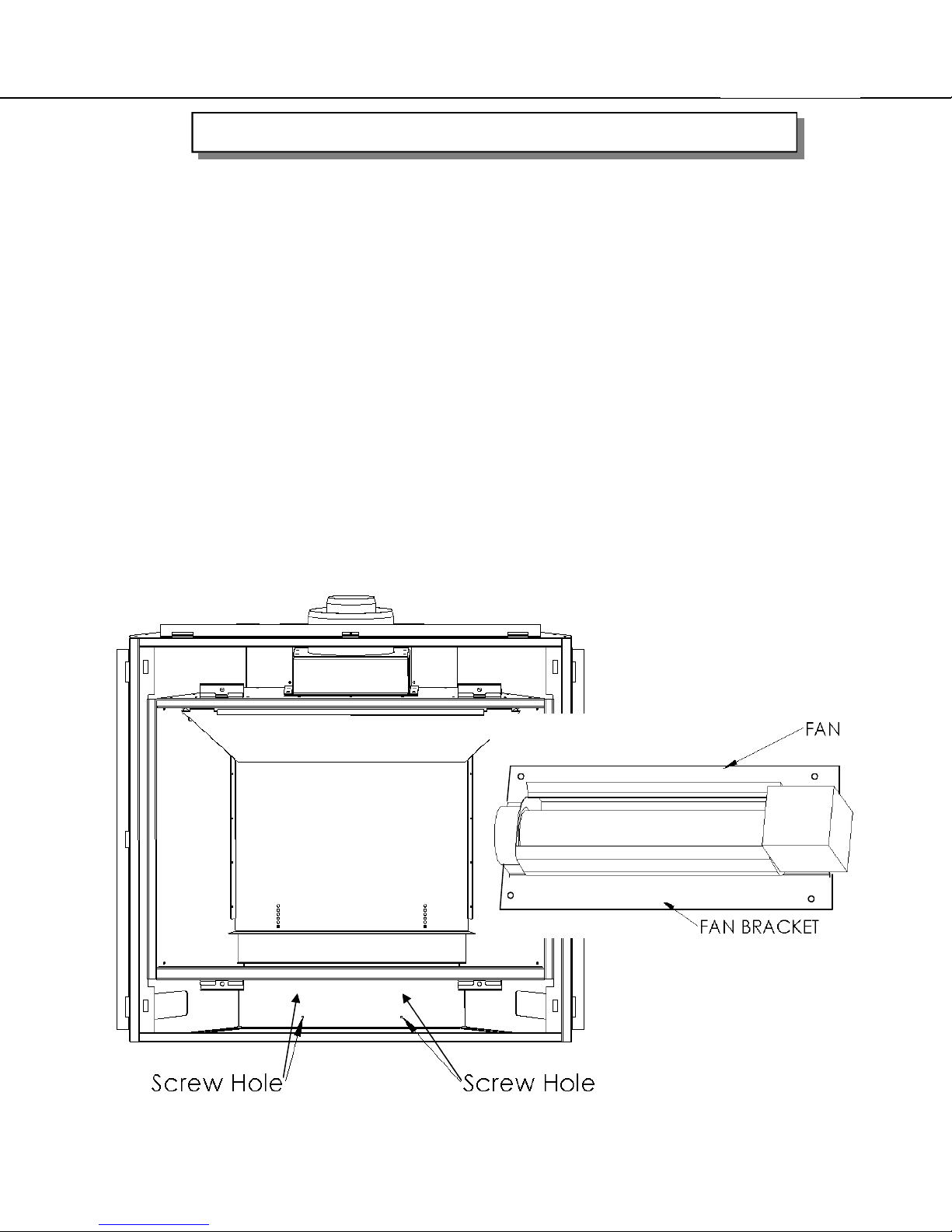
FAN KIT REMOVAL & INSTALLATION
Before removing the fan be sure to let unit cool to room temperature, disconnect electrical power
to the unit, shut off gas to the unit and disconnect the gas line to the appliance.
To remove fan, for maintenance or replacement:
1) Remove the louvers and door.
2) Remove the logs, brick panels and burner. Note: Be careful when handling these items as they
may break if dropped or handled roughly.
3) Remove fan guard (figure 24) and valve tray.
4) Disconnect wires, be sure to label wires prior to disconnecting to ensure they are replaced in the
correct location.
5) Remove the four screws (Figure 22) and take fan out.
6) Installation is the reverse order of the previous steps
See next page for continued installation instructions.
Figure 22
Figure 23

THE CALDERA
Page 49
FAN KIT INSTALLATION - continued
Figure 24

THE CALDERA
Page 50
Replacement Parts list for Caldera
No
Part # Description QTY Unit
expl.
view
OM7405 OWNERS MANUAL, CALDERA DVT/DVR 1 EA
Z0758A CONVERSION KIT-NATURAL GAS TO PROPANE 0-4,500ft 1 EA
Z0758B CONVERSION KIT-NATURAL GAS TO PROPANE 4,500-6,500ft 1 EA
Z0758C CONVERSION KIT-NATURAL GAS TO PROPANE 6,500-8,500ft 1 EA
Z0759A CONVERSION KIT-PROPANE TO NATURAL GAS 0-4,500ft 1 EA
Z0759B CONVERSION KIT-PROPANE TO NATURAL GAS 4,500-6,500ft 1 EA
Z0759C CONVERSION KIT-PROPANE TO NATURAL GAS 6,500-8,500ft 1 EA
01 0254C DOOR GASKET (part # FTI 1071, 114" long) 1 EA
02 0244 GLASS CERAMIC (33-1/8" x 22-15/16") 1 EA
03 M \Z7405B BURNER TRAY 1 EA
04 Z7454 BRICK PANEL SET 1 EA
05 0712A PSE PILOT (PSE-C7-520) 1 EA
06 M \SIT0584302 CONTROL MODULE 1 EA
07 M \SIT0885001 SIT VALVE - MODEL PROFLAME 885 1 EA
08 M \SIT0584521 RECEIVER / BATTERY PACK 1 EA
09 0719D FAN 1 EA
10 0136 RHEOSTAT FAN SPEED CONTROL 1 EA
M \SIT0584121 FAN MODULE 1 EA
13 1144AA SNAPDISK 1 EA
14 7412 FLUE BAFFLE 1 EA
15 7480 60 % VENT RESTRICTOR 1 EA
16 M \SIT0584023 REMOTE TRANSMITTER SIT 1 EA
M \SIT0584912 MODULE/VALVE WIRE HARNESS 1 EA
M \SIT0584905 WIRE HARNESS RECEIVER 1 EA
0822 LOG SET (6 PIECES) 1 EA
0779A LIGHT BULB HALOGEN BI-PIN 12V 20W G6.35 1 EA
Parts can be ordered through your local dealer or distributor by giving PART #
and DESCRIPTION.

THE CALDERA
Replacement Parts list for Caldera
1
Page 51

Page 52
THE CALDERA
Blaze King Warranty
Gas stoves manufactured by Blaze King Industries and/or Valley Comfort Systems Inc. are covered by a limited lifetime warranty against
manufacturers defects in material and workmanship. Details of this comprehensive warranty program are outlined below. In addition to the
terms outlined for the limited lifetime warranty, our products carry a 5 year warranty which covers mechanical and electrical components
includinglabor costs outlined below. The combination of these warranty policies provide a very strong coverage package that we are proud
to offer you, our customers. Our Blaze King tradition of building high quality products for over 25 years is really your most important
assurance of quality but it's nice to know that should something fail (and it occasionally does) you are covered by a warranty policy that
leads the industry. To ensure the coverage is in place you must have your unit properly installed by an authorized Blaze King dealer and
you must register your ownership. Blaze King's warranty policy applies only to units sold, installed and/or for use in the USA or
Canada. No person is authorized to modify this warranty or make any additional warranties on behalf of the manufacturer, Blaze
King.
Components andparts5 year warranty:
Blaze King warrants the following parts; blower motors, door gasket, blower speed control, logs, pilot assembly, gas valve, gas lines,
thermocouple and/or thermopile against defects in material or workmanship to the original purchaser, for five years following the date of
purchase.Consumable items, such as batteriesand light bulbs are not covered by warranty.
Labor costs during the 5 year warranty period:
Blaze King manufacturers warranty covers labor costs to the original purchaser based on our schedule of approved charges, provided to
our authorizeddealers.BlazeKing will only beresponsiblefor labor costs provided by ourauthorized dealers andbasedupon the schedule.
LimitedLifetimeCoverage
This warranty contains different terms that cover specific parts of the gas appliance. Blaze King warrants the following parts of the gas
appliance against defects in material or workmanship to the original retail purchaser. For the first five years of ownership, the combustion
chamber, heat exchanger and burners will be replaced by Blaze King, conditional upon production availability. From year 6 through to the
end of ownership by the original purchaser, Blaze King will provide replacement or repair of the aforementioned parts, conditional upon
current production availability, at 50% of current retail price but does not cover any charges relating to labor. This portion of the warranty
coverage isnot transferableand applies only to the original purchaser.
How to GetService
If this product requires repair or replacement due to defectsin material or craftsmanship duringthe first five years ofownership,contactyour
Blaze King dealer and explain the nature of the problem. If the dealer is unable to repair or replace the product to your satisfaction then
contact Blaze King at 509-522-2730 in the USA or 250-493-7444 in Canada. If a replacement part is sent directly to you, please contact
Blaze King to obtain a Return Authorization Number (RA#) for all defective parts. Blaze King will refuse delivery of any returned packages
not clearly showing an (RA#). All expenses relating to the shippingof defective parts or entirestoveswill be atpurchaser's expense.
BlazeKings Responsibilities:
If the purchaser has complied with all the terms and conditions of this warranty and if the purchaser has notified Blaze King of the defect
prior to the expiration of any warranted items, the following procedure will occur. Blaze King will inspect the product to determine that there
is indeed a defect and that the defect is covered by warranty. Blaze King will either repairor replace the product at its' discretion. Under no
condition whatsoever does Blaze King provide or imply warranty coverage for venting components used in the installation of our products.
This warranty details the obligations and liabilities of Blaze King and no other warranties are expressed or implied. Blaze King reserves the
right to investigate and settle all claims against warranted parts at their discretion. In no event shall Blaze King be held responsible for
indirect or consequential damages of any nature which are in excess of the original purchase price of the product. Blaze King may at its'
discretion discharge any or all obligationsby refundingthe wholesale price of anydefective part or parts.
Misuseof Stove NullifiesWarranty:
The above warranty is conditioned upon the proper installation and use of the product according to the manufacturers instructions as
specified in the "Owners Installation & Operations Instructions" and in compliance with applicable local building and fire codes. Blaze King
recommends thelocal building inspector or firedepartment inspect the unit prior to initialuse. Consult the "Owners Installation & Operations
Instructions" supplied with each unit prior to installation or operation. Alteration, abuse, lack of maintenance, faulty repairs or misuse will
void the warranty. Abuse includes but is not limited to the use of fuels other than as specified in the "Owners Installation & Operations
Instructions."
Legal Rights of Purchaser:
This warrantygives you specific legal rights and you may have other rights that varyfromstate to state (orprovince toprovince).
BlazeKing Assurance Plan:
Includedwitheach gas stove manufactured by Blaze King isa Warranty Card, which must be completed in its entirety and returned to Blaze
king within ten days from thedate of purchase. Blaze King will beunable to properly administerthe warrantyif the cardis not completed and
registered on file. The Protection Plan willpay torepair and or replace parts which fail under normal usage at labor rates established by this
Agreement. Extra charges such as mileage, overtime or shipping are not covered. Nuisance calls are not covered by the Plan. This Plan is
for residential stoves and does not apply to commercial applications. Only repairs attributed to normal failure of the electronic and
mechanical functions of thestove are covered. Failure due butnot limited to, abuse,negligence, impact, fire, lightning, power failures and or
surges, rust and corrosion are not covered. Damage and or repairs to cabinets and all exterior components, remote controls, and normal
maintenance, related duct work, power surges, electrical spikes or electrical circuit overloads, filters, knobs, glass, gaskets, block and tile
etc., are not covered. Additional or unusual utility bills incurred due toany malfunctionor defect in equipment listed on the Plan, labor cost of
gaining access to or removal of a unit that requires special equipment or tools such as cranes, ladder trucks, etc., are not covered. These
include but are not limited to, cleaning, adjustments of the customer controls and customer product education. Labor, materials, expenses
or equipment required to comply with thelaw and orregulations setforthby any governmentalagencies are not covered by thisPlan.

THE CALDERA
Page 53
NOTES
SERVICE HISTORY
DATE CORRECTIVE ACTION (INCLUDE REPLACEMENT PARTS)
 Loading...