

Page 1
ASHFORD 25(AF25)
SOLID FUEL WOOD CATALYTIC STOVE
THIS MANUAL PERTAINS
TO UNITS WITH SERIAL
NUMBERS:
17.1252 to 17.1256 inclusive
17.1277 to 17.1282 inclusive
17.1287 and above
SERIAL #
LOCATION
Date Installed:_____________
Serial No.: _____________
This heater meets the 2015 U.S. Environmental Protection Agency’s particulate emission limits for wood heaters sold after May 15, 2015.
Installer: Please complete the details on the back cover
and leave this manual with the homeowner.
0142WN017S
The authority having jurisdiction (such a municipal building department, fi re department, etc.) should be
consulted before installation to determine the need to obtain a permit.
Homeowner: Please SAVE THESE INSTRUCTIONS for future reference.
OPERATION & INSTALLATION MANUAL
Manufactured By
Valley Comfort Systems Inc., 1290 Commercial Way, Penticton, BC, V2A 3H5, Canada
Phone: 250-493-7444 w Fax: 250-493-5833 w www.blazeking.com w [email protected]
Pour la version française de nos manuels S.V.P. vous référez à notre site web: www.blazeking.com
180-AF25 v1.07 October 2, 2018
Page 2

Page 2
TABLE OF CONTENTS
INTRODUCTION _____________________________________________________________ 4
SPECIFICATIONS _____________________________________________________________ 5
EMISSIONS __________________________________________________________________ 5
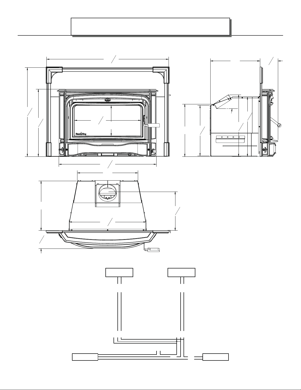
APPLIANCE DIMENSIONS ______________________________________________________ 6
DIMENSIONS—#Z2091 AF25 29 1/4” Shroud ................................................................................ 6
DIMENSIONS—#Z2093 AF25 32 1/4” Shroud ................................................................................ 7
Electrical Diagram—Ashford 25 ....................................................................................................... 7
CERTIFICATION LABEL ________________________________________________________ 8
LABEL LOCATION ____________________________________________________________ 8
SAFETY PRECAUTIONS ________________________________________________________ 9
INSTALLATION INSTRUCTIONS _________________________________________________ 12
FLOOR PROTECTION .................................................................................................................... 12
COMPONENTS REQUIRED ........................................................................................................... 12
PARTS INCLUDED WITH THE ASHFORD INSERT .....................................................................12
REQUIRED SHROUD OPTIONS .................................................................................................... 12
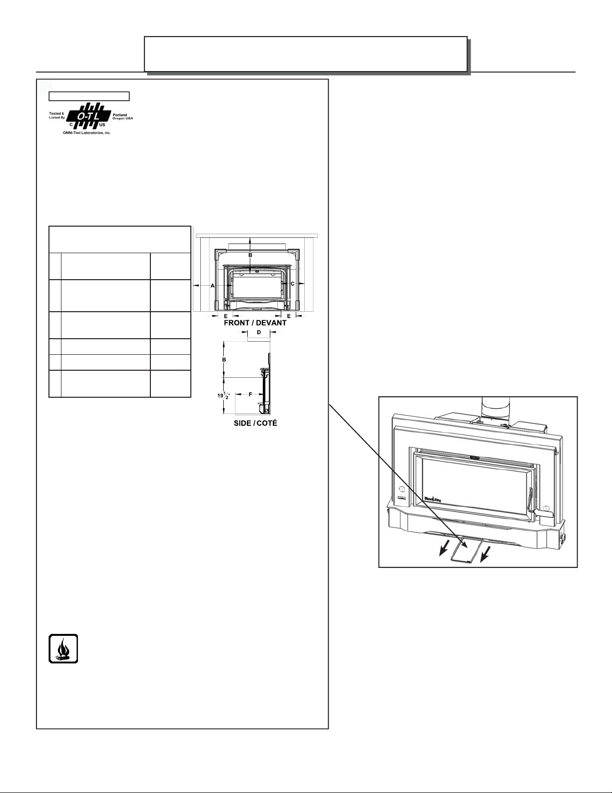
MINIMUM CLEARANCES for AF25............................................................................................... 13
COMBUSTION AIR ......................................................................................................................... 14
DRAFTING PERFORMANCE ......................................................................................................... 14
ROLE OF THE CHIMNEY ............................................................................................................... 14
INSPECT CHIMNEY ....................................................................................................................... 15
PLANNING STOVE PLACEMENT ................................................................................................. 15
FRONT CAST REMOVAL ................................................................................................................ 16
STOVE ASSEMBLY .......................................................................................................................... 16
Flue collar assembly removal ............................................................................................................ 16
CHIMNEY........................................................................................................................................ 20
OPERATING INSTRUCTIONS ___________________________________________________ 21
YOUR FIRST FIRE! .......................................................................................................................... 21
THERMOSTAT ................................................................................................................................ 21
BYPASS ............................................................................................................................................ 21
CATALYTIC THERMOMETER ....................................................................................................... 22
SELECTING WOOD ........................................................................................................................ 22
HOW TO USE MOISTURE METERS .............................................................................................. 23
EFFICIENCY .................................................................................................................................... 23
LIGHTING THE FIRE ..................................................................................................................... 24
RELOADING PROCEDURE (with the catalyst temperature in the active red zone) ......................... 25
RELOADING PROCEDURE (with the catalyst temperature still in the inactive zone) ..................... 25
OPTIMAL THERMOSTAT SETTING ............................................................................................. 26
FAN OPERATION ........................................................................................................................... 26
ICE - FORMATION AND PREVENTION ....................................................................................... 26
WOOD BURNING IN THE SHOULDER SEASON ......................................................................... 27
CATALYST MONITORING ______________________________________________________ 28
CATALYTIC COMBUSTOR, TESTING ........................................................................................... 28
CATALYTIC COMBUSTOR, CLEANING ....................................................................................... 28
CATALYTIC COMBUSTOR, TROUBLESHOOTING ...................................................................... 29
CATALYTIC COMBUSTOR, REPLACEMENT ............................................................................... 31
AF25
180-AF25 v1.07 October 2, 2018
Page 3

AF25
MAINTENANCE ______________________________________________________________ 34
RUN-AWAY OR CHIMNEY FIRE .................................................................................................... 34
CREOSOTE FORMATION AND REMOVAL .................................................................................. 34
ASH REMOVAL ............................................................................................................................... 35
LOADING DOOR GASKET INSPECTION...................................................................................... 36
LOADING DOOR GASKET REPLACEMENT................................................................................. 36
BYPASS DOOR GASKET RETAINER REPLACEMENT #Z2022 ..................................................... 37
DOOR GLASS GASKET INSPECTION ........................................................................................... 39
DOOR GLASS GASKET REPLACEMENT ...................................................................................... 39
DOOR GLASS, REPLACEMENT ..................................................................................................... 39
DOOR GLASS, CLEANING ............................................................................................................. 39
LOADING DOOR TENSION ADJUSTMENT ................................................................................. 40
LOADING DOOR HINGE ADJUSTMENT ..................................................................................... 40
FAN ASSEMBLY .............................................................................................................................. 41
THERMOSTAT ................................................................................................................................ 41
TROUBLESHOOTING __________________________________________________________ 42
REPLACEMENT PARTS ________________________________________________________ 45
WARRANTY _________________________________________________________________ 48
INSTALLER NOTES ____________________________________________________________ 52
TABLE OF CONTENTS
Page 3
180-AF25 v1.07 October 2, 2018
Page 4
Page 4
• THIS APPLIANCE IS HOT WHEN OPERATED AND CAN CAUSE SEVERE BURNS IF CONTACTED.
ANY CHANGES OR ALTERATIONS TO THIS APPLIANCE OR ITS CONTROLS CAN BE DANGEROUS AND IS PROHIBITED BY
FEDERAL AND STATE LAWS.
• Do not operate appliance before reading and understanding operating instructions. Failure to operate appliance according to operating
instructions could cause fi re or injury.
• Before installing this appliance, contact the local building or fi re authority and follow their guidelines.
• This appliance must be installed by a qualifi ed installer.
• Risk of burns. The appliance should be turned off and cooled before servicing.
• Do not operate without fully assembling all components.
• Do not let the appliance become hot enough for any part to glow red.
• Do not install damaged, incomplete or substitute components.
• Risk of cuts and abrasions. Wear protective gloves and safety glasses during installation. Sheet metal edges may be sharp.
• Children and adults should be alerted to the hazards of high surface temperature and should stay away to avoid burns or clothing
ignition.
• Young children should be carefully supervised when they are in the same room as the appliance. Toddlers, young children and
others may be susceptible to accidental contact burns. A physical barrier is recommended if there are at risk individuals in the house.
To restrict access to an appliance or appliance, install an adjustable safety gate to keep toddlers, young children and other at risk
individuals out of the room and away from hot surfaces.
• Clothing or other fl ammable material should not be placed on or near the appliance. Objects placed in front of the appliance must be
kept a minimum of 48” away from the front face of the appliance.
• Due to high temperatures, the appliance should be located out of traffi c and away from furniture and draperies.
• Ensure you have incorporated adequate safety measure to protect infants / toddlers from touching hot surfaces.
• Even after the appliance is out, all surfaces, including the glass and/or any attachment will remain hot for an extended period of time.
• Check with your local hearth specialty dealer for safety hearth guards to protect children from hot surfaces. These guards must be
fastened to a wall and/or to the fl oor.
• Any safety guard removed for servicing must be replaced prior to operating the appliance.
• Under no circumstances should this appliance be modifi ed.
• This appliance must not be connected to a chimney fl ue pipe servicing a separate solid fuel burning appliance.
• Do not operate the appliance with the glass door removed, cracked or broken. Replacement of the glass should be done by a licensed
or qualifi ed service person.
• Do not strike or slam shut the appliance glass door.
• Operate only with the doors tightly closed.
• Appliance will over-fi re if door is not shut and latched.
• Only certifi ed doors / optional fronts / and surrounds for inserts with the unit are to be installed on the appliance.
• Keep the packaging material out of reach of children and dispose of the material in a safe manner. As with all plastic bags, these are
not toys and should be kept away from children and infants.
• If the appliance is not properly installed, a house fi re may result. Do not expose the appliance to the elements (rain, etc.) and keep the
appliance dry at all times.
• The chimney must be sound and free of cracks and obstructions. Clean your chimney regularly as required.
• Never use gasoline, gasoline-type lantern fuel, kerosene, charcoal lighter fl uid, or similar liquids to start or ‘freshen up’ a fi re in this
heater. Keep all such liquids well away from the heater while it is in use.
• Your appliance requires periodic maintenance and cleaning. Failure to maintain your appliance may lead to smoke spillage in your
home.
• Higher effi ciencies and lower emissions will generally result when burning air dried seasoned woods, as compared to wet, green or
freshly cut wood. Burning wet unseasoned wood can cause excessive creosote accumulation. When ignited it can cause a chimney
fi re that may result in a serious house fi re.
• The appliance is designed to burn seasoned wood only. Do not burn treated wood, coal, charcoal, colored paper, cardboard, solvents
or garbage.
• Burn wood directly on the fi rebricks. Do not use a grate or elevate the fi re.
• Do not store wood within appliance installation clearances or within the space required for re-fueling and ash removal.
• Ashes must be disposed in a metal container with a tight lid and placed on a non-combustible surface well away from the home or
structure until completely cool.
INTRODUCTION
AF25
CALIFORNIA PROPOSITION 65
WARNING: This product can expose you to chemicals including
benzene, which is known to the State of California to cause cancer and birth
defects or other reproductive harm. For more information:
www.P65Warnings.ca.gov
180-AF25 v1.07 October 2, 2018
Page 5
AF25
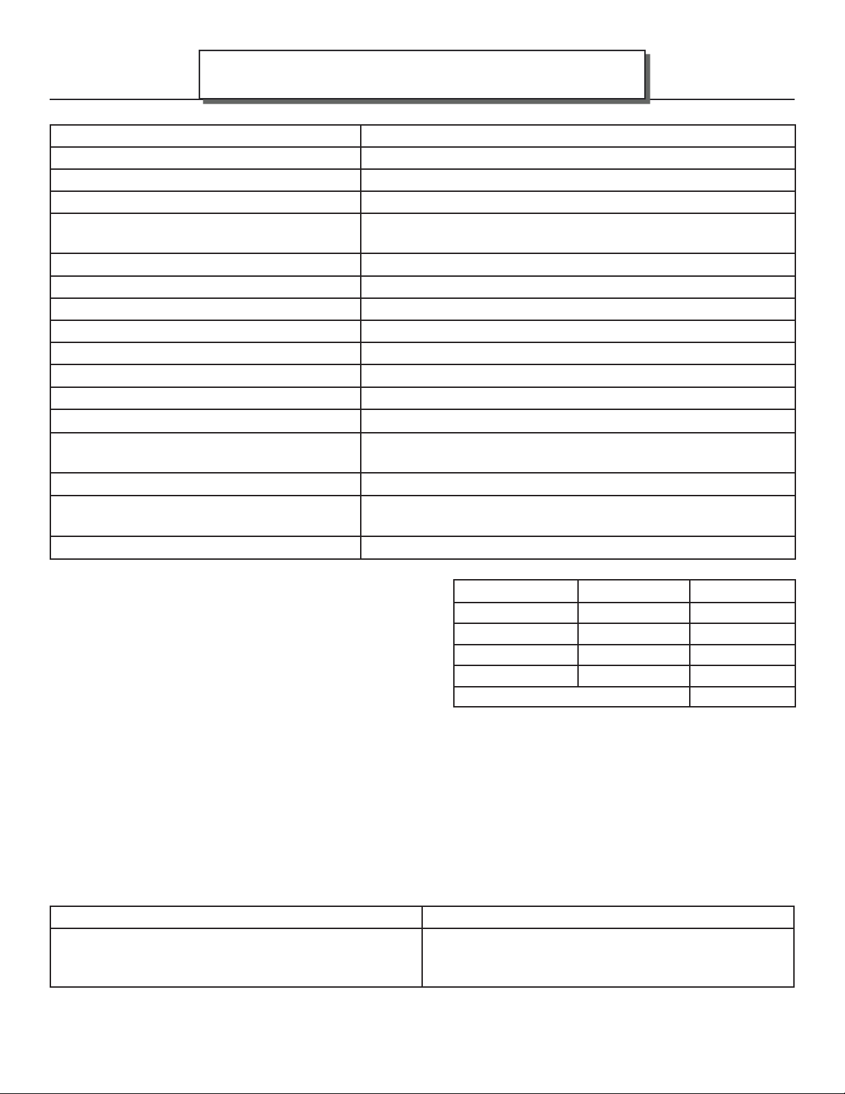
Model Ashford 25 (AF25) (catalytic)
Height and width without shroud 24 3/8” x 35 3/8” (613 mm x 899 mm)
Width of fi rebox enclosure (behind shroud) 27 7/8” (708 mm)
Overall depth and height of fi rebox
Flue collar size and distance from shroud
back
Fire door opening 25 1/4” x 10 5/8” (642 mm x 270 mm)
Firebox depth 16 3/4” (426 mm) brick to brick, 18” (457 mm) brick to glass
Firebox width average 20 1/2” (521 mm)
Firebox height 10” (254 mm)
Fire box capacity 2.3 cu. ft.
Recommended Fuel length 16” max. (407 mm)
Wood capacity (approximate): White oak - 53 lbs. (24.04 kg)
Construction 10 gauge & 1/4” fi rebox, refractory brick lined. Cast iron outer
Shipping Weight (Firebox only) 415 lbs. (189 kg)
Chimney recommendation (Minimum) 15’ from stove top to chimney cap: Insulated liner
Minimum fi replace opening 29”L x 22”H x 19P” (737 mm x 559 mm x 483 mm)
SPECIFICATIONS
18 3/8” x 21 5/8” (639 mm x 588 mm)v
6” I.D., 14 3/8” (366 mm)
Fir - 35 lbs. (15.88 kg)
shell.
recommended
Page 5
This unit was tested and listed UL 1482, Ed 7 2011 and
ULC S628-93 by OMNI-Test Laboratories.
This manual describes the installation and operation of the
Ashford AF25 catalytic equipped wood heater.
This heater is certifi ed to comply with the 2020 U.S.
Environmental Protection Agency’s particulate emission
standards using crib wood.
Under specifi c test conditions this heater has been shown
to deliver heat at rates ranging from 10097 to 26290 Btu/hr.
This wood heater has a manufacturer-set minimum low burn rate that must not be altered. It is against federal
regulations to alter this setting or otherwise operate this wood heater in a manner inconsistent with operating
instructions in this manual.
This wood heater contains a catalytic combustor, which needs periodic inspection and replacement for proper
operation. It is against federal regulations to operate this wood heater in a manner inconsistent with operating
instructions in this manual, or if the catalytic element is deactivated or removed.
The combustor supplied with this heater is a 115.0335 metal combustor. Consult the catalytic combustor
warranty also supplied with this wood heater. Warranty claims should be addressed to:
in Canada in USA
Blaze King Industries / Valley Comfort Systems
Warranty Department, 1290 Commercial Way
Penticton, BC Canada V2A 3H5, Ph: 250-493-7444
Walla, Walla, Washington 99362, Ph: 509-522-2730
EMISSIONS CO Average(%) g/hr
Low Burn 0.05 0.31
Med-low Burn 0.18 0.33
Med-high Burn 0.12 1.48
High Burn 0.08 1.93
EPA emission rate weighted average .90 g/hr
Blaze King Industries
Warranty Department, 146A Street
180-AF25 v1.07 October 2, 2018
Page 6
Page 6
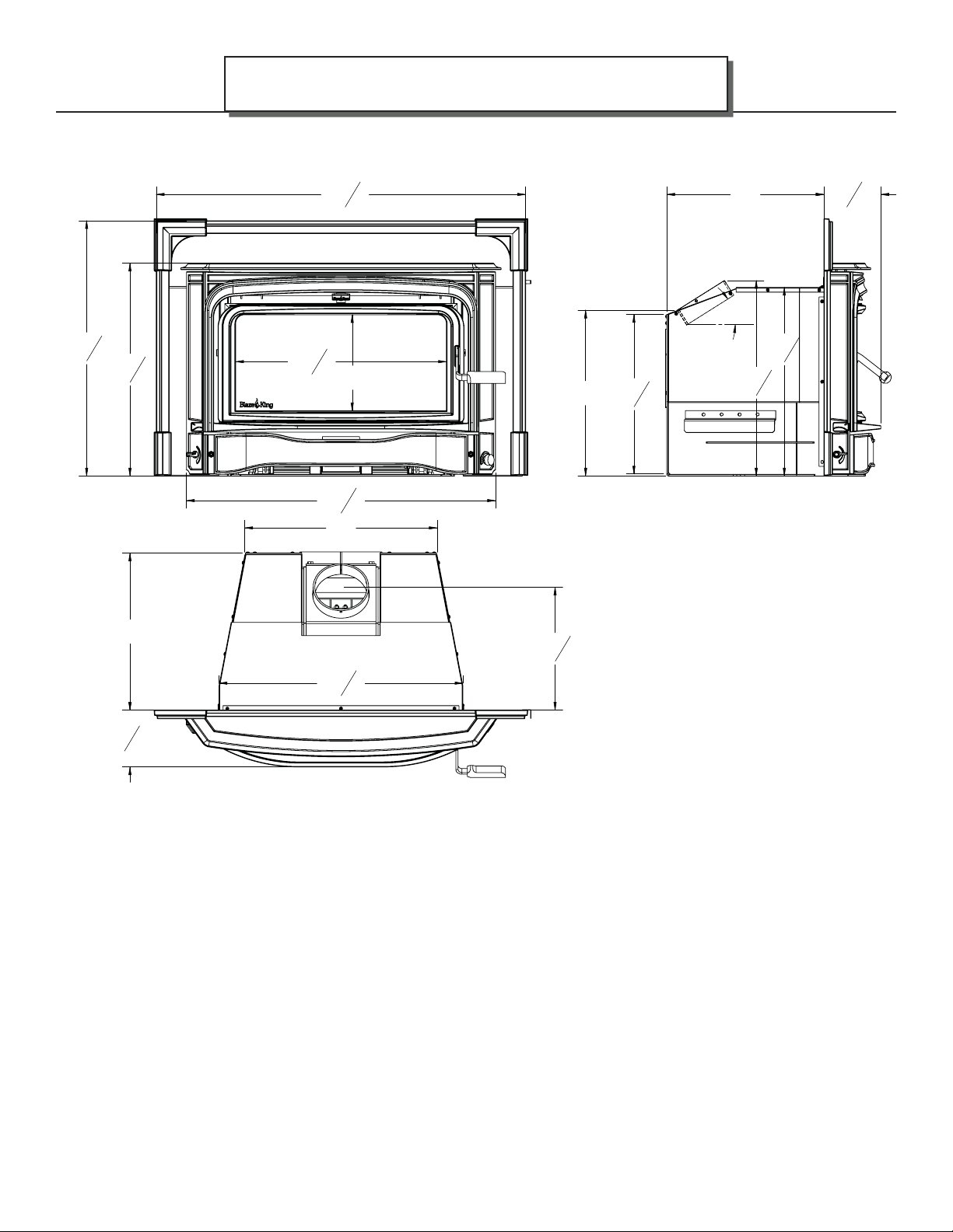
APPLIANCE DIMENSIONS
DIMENSIONS—#Z2091 AF25 29 1/4” Shroud
AF25
180-AF25 v1.07 October 2, 2018
Page 7
AF25
APPLIANCE DIMENSIONS
DIMENSIONS—#Z2093 AF25 32 1/4” Shroud
Page 7
Electrical Diagram—Ashford 25
FAN FAN
POWER CORD
G M F
M F
F M
F M
G G
F M
M F
F M
G M F
F M
F M
M F
RHEOSTAT
180-AF25 v1.07 October 2, 2018
Page 8
Page 8
CERTIFICATION LABEL
AF25
SN - 17
Report #0142WN017S
PREVENT HOUSE FIRES - Install and use only in accordance with Blaze King’s installation and operation instructions.
Install and use in a code complying fi replace only. Contact local building or fi re offi cials about restrictions and installation
inspection in your area. Do not remove bricks or mortar in masonry fi replace. Do not use grate or elevate fi re. Inspect
and clean chimney frequently - under certain conditions of use, creosote buildup may occur rapidly. CHIMNEYS: Do not
connect this unit to a chimney fl ue serving another appliance. Do not over fi re - if heater or chimney glows, you are over
fi ring. COMPONENTS REQUIRED FOR INSTALLATION: 6" stainless steel liner - listed to: UL 1777, ULCS635 OR ULCS640.
PRÉVENTION DES INCENDIES- Installer et utiliser cet appareil conformément aux instructions d’installation et du mode
de fonctionnement de Blaze King. Installer et utiliser seulement selon le code conforme, concernant les foyers. Contacter
le code du bâtiment local ou le département des incendies à propos des restrictions et des inspections des installations
de votre région. Ne pas retirer les briques ou le mortier dans votre foyer de maçonnerie. Ne pas utiliser de grille et ne
pas surélever le feu. Inspecter et nettoyer votre cheminée fréquemment- dans certaines conditions d’utilisation, une
accumulation de créosote peut se produire rapidement. Cheminées : Ne pas raccorder cet appareil à un conduit de
cheminée desservant un autre appareil. Ne pas surchauff er- si l’appareil ou les conduits deviennent rougeoyants, vous
êtes en surchauff e. Composantes requises pour l’installation : Gaine de 6po en acier inoxydable inscrite sous : UL 1777,
ULCS635 Ou ULCS640.
Minimum clearances to combustibles, measured from fi rebox
door fl ange / Dégagements minimum requis entre l’appareil à
tout matériau combustible à partir du rebord de l’ouverture de
porte de la chambre à combustion.
Side of door fl ange to combustible
wall. / Du côté du rebord de
A
l’ouverture de porte à tout mur
combustible.
Top of door fl ange to bottom of
mantel and combustible facing. / Du
dessus du rebord de l’ouverture de
B
porte au bas du manteau et de toute
façade combustible.
Side of door fl ange to side
combustible facing. / Du côté du
C
rebord de l’ouverture de la porte à
toute surface de côté combustible.
Mantle width maximum. / Largeur
D
maximum du manteau.
Minimum hearth side extension * /
E
Extension latérale minimum du foyer
Mimimum hearth front extension /
F
Extension frontale minimum du foyer
* Measured from each side of the fuel loading and ash removal
openings / Mesuré à partir de chaque côté de l’ouverture de la porte
de chargement et du tiroir de cendre
ASHFORD INSERT - Encastrable Ashford
BLAZE KING CATALYST STOVE - BLAZE KING ENCASTRABLE CATALYTIQUE
Room heater, solid fuel type. / Appareil de chauff age approuvé pour type de
carburant solide.
MODEL / MODÈLE: AF25
Tested to / Testé pour: UL 1482-11 (R2015) / ULC S628-93
CERTIFIED IN BOTH UNITED STATES AND CANADA / CERTIFIÉ POUR LES ÉTATSUNIS ET LE CANADA
13.5" / 343 mm
20" / 508 mm
10" / 254 mm
12" / 305 mm
8"* / 204mm
16" / 407 mm
USA
18" / 458 mm
CANADA
FLOOR PROTECTION / PROTECTION DU PLANCHER:
A non-combustible (UL1618 type 1) fl oor protection is required for all installations extending 16” (in USA) or 18” (in Canada)
in front of the door and extending 8” to either side of the door opening. With the fl oor fl ush with the bottom of the appliance
and to an elevation of 5” below the fi rebox bottom, a 1/2” layer of thermal protection where R=1.06 is required. Anything 0 to
5” below the fi rebox bottom requires a (UL 1682 type 2) thermal protection where R=1.06 is required.
Une protection de plancher non combustible est requise (UL1618 type 1) pour toutes les installations s’étendant de 16 po
(aux USA) ou de 18 po (au Canada) en avant de la porte et s’étendant de 8 po de chaque côté de l’ouverture de porte. Avec le
plancher au même niveau du fond de l'appareil et à une élévation de 5 po en dessous du fond de la chambre à combustion,
une couche de protection thermique de 1/2" où R = 1,06 est nécessaire. Tout de 0 à 5 "en dessous du fond de la chambre à
combustion nécessite une (UL 1,682 type 2) protection thermique R = 1,06 est nécessaire.
Electrical rating: (120V, 60Hz, 0.75 Amps. Risk of electrical shock. Disconnect power before servicing unit. Do not route
power cord in front of or beneath heater).
U.S. ENVIRONMENTAL PROTECTION AGENCY - Certifi ed to comply with 2020 particulate emission standards using crib
wood.(EPA test methods 28R/5G, ASTM E2515, and ASTM E2780, with an emission-rate of 0.90 g/hr). This wood heater
needs periodic inspection and repair for proper operation. Consult the owner’s manual for further information. It is against
federal regulations to operate this wood heater in a manner inconsistent with the operating instructions in the owner’s
manual, or if the catalytic element is deactivated or removed. Only operate with doors closed. Open door to feed fi re ONLY.
Open the bypass before opening the door. Do not obstruct combustion air openings. For Use With Solid Wood Fuel Only
- Do not burn other fuels, this may make the catalyst in the combustor inactive. The performance of the catalytic device or
its durability has not been evaluated as part of the certifi cation. Metal combustor part number: 115.0335. Provide adequate
outside air for combustion. *Replace with only ceramic glass, 5 mm. Thickness.
Estimation électrique: (115 VAC, 60 Hz, 0.58 Amps. Risque d’électrocution débrancher le courant avant de réparer l’unité. Ne
pas faire courir le fi l l’alimentation en avant ou en dessous de l’appareil de chauff age).
L’AGENCE DE PROTECTION ENVIRONNEMENTALE DES U.S. - Certifi é conformément aux normes d'émission de particules
2020 , en utilisant du bois machiné (méthodes d'essai EPA 28R / 5G, ASTM E2515 et ASTM E2780, avec un taux d'émission
de 0,90 g /hre). Cet appareil de chauff age au bois nécessite des inspections périodiques et des réparations pour un
fonctionnement adéquat. Consulter le manuel du propriétaire pour plus d’informations. Il est contre les règlements
fédéraux de faire fonctionner cet appareil de chauff age à l’encontre des instructions d’utilisation fournies dans le manuel du
propriétaire, ou si l’élément catalytique a été enlevé ou désactivé. *UTILISER L’appareil UNIQUEMENT AVEC LES PORTES
FERMÉES. Ouvrir la porte SEULEMENT pour alimenter le feu. *NE PAS OBSTRUER L’ENTRÉE D’AIR DE COMBUSTION.
Fournir l'apport d’air extérieur adéquat pour alimenter la combustion. Utiliser uniquement avec des combustibles
solides - ne pas brûler aucun autre combustible, ce qui pourrait désactiver le catalyseur de la chambre à combustion. La
performance du catalyseur ou sa longévité n’a pas été évaluée dans le cadre de la certifi cation. Numéro du catalyseur:
Z4400G.* Employer seulement un catalyseur en verre en céramique d’une épaisseur de 5mm si le remplacement de celui-ci
est nécessaire.
CAUTION: HOT WHILE IN OPERATION. DO NOT TOUCH. KEEP CHILDREN, CLOTHING AND FURNITURE
AWAY. CONTACT MAY CAUSE SKIN BURNS. READ THIS LABEL AND INSTRUCTION MANUAL BEFORE
OPERATING HEATER
ATTENTION: CHAUD LORS DU FONCTIONNEMENT. GARDEZ LES ENFANTS, VÊTEMENTS ET MEUBLES
ÉLOIGNÉS. UN CONTACT AVEC LA PEAU PEUT OCCASIONNER DES BRÛLURES. LIRE CETTE ÉTIQUETTE
ET LES INSTRUCTIONS D’INSTALLATION AVANT DE FAIRE FONCTIONNER CET APPAREIL.
MANUFACTURED IN:
Blaze King Industries
USA:
146A Street, Walla Walla, WA. 99362
CANADA: Valley Comfort Systems
1290 Commercial Way, Penticton, B.C. V2A 3H5
JAN FEB MAR APR MAY JUN
JUL AUG SEP OCT NOV DEC
2017 2018 2019 2020 2021 2022
MANUFACTURE DATE
170-0229 [02 18].indd
LABEL LOCATION
180-AF25 v1.07 October 2, 2018
Page 9
AF25
IF THIS BLAZE KING APPLIANCE IS NOT PROPERLY INSTALLED OR OPERATED, A HOUSE FIRE MAY
RESULT. TO REDUCE THE RISK OF FIRE, FOLLOW THE INSTALLATION INSTRUCTIONS. CONTACT LOCAL
BUILDING OR FIRE OFFICIALS ABOUT RESTRICTIONS AND INSTALLATION INSPECTION
PLEASE READ THIS ENTIRE MANUAL BEFORE YOU INSTALL AND USE YOUR NEW APPLIANCE. FAILURE TO
FOLLOW INSTRUCTIONS MAY RESULT IN PROPERTY DAMAGE, BODILY INJURY, OR EVEN DEATH.
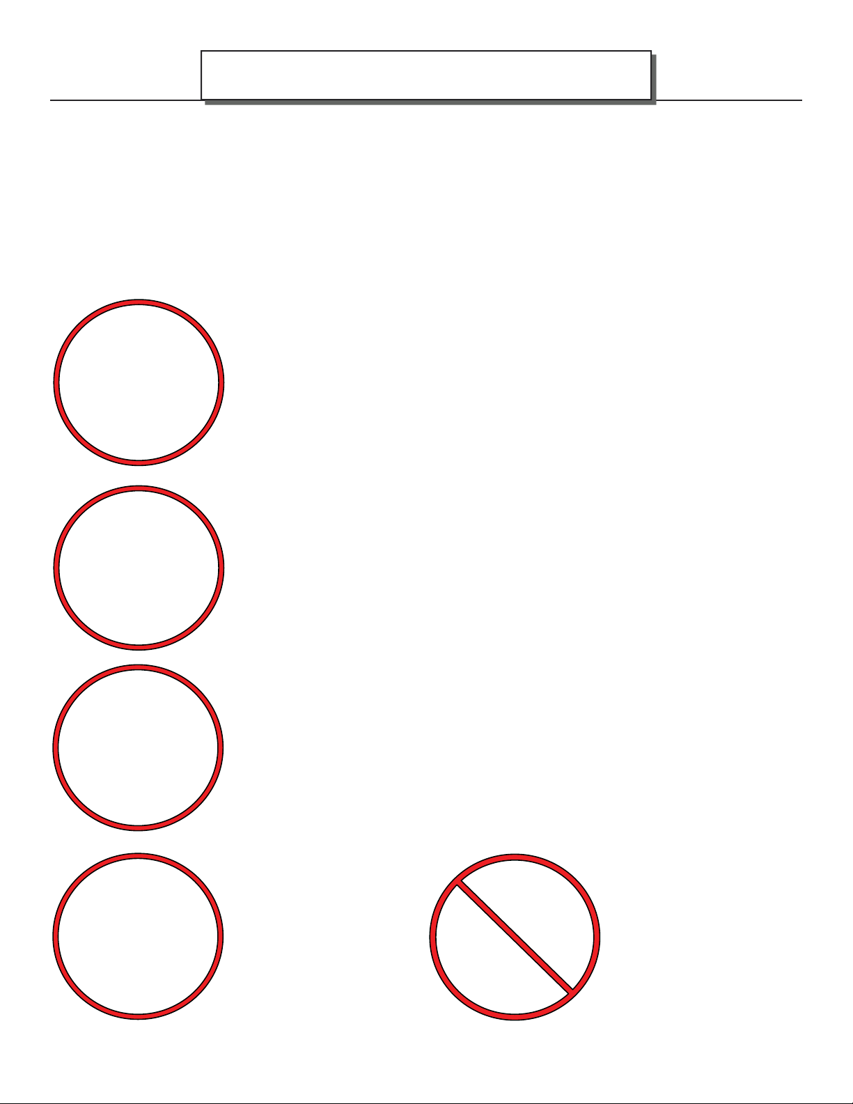
This appliance must be connected to a listed high temperature (UL1777,ULC635,ULC640)
approved masonry chimney with a fl ue liner.
Chimney and chimney connector must be in good condition and kept clean.
NEVER vent the stove to other rooms of the building. Must be vented to the outside ONLY.
NEVER use a chimney or chimney connector smaller then the stove exhaust, unless
approved by your local inspector.
NEVER vent the stove into a “Class B” gas vent chimney.
DO NOT CONNECT IN CONJUNCTION WITH ANY AIR DISTRIBUTION DUCTWORK
UNLESS SPECIFICALLY APPROVED FOR SUCH INSTALLATIONS.
SAFETY PRECAUTIONS
REQUIREMENTS IN YOUR AREA.
Page 9
Inspect the chimney connector and chimney regularly during each burning season and
clean when necessary.
DO NOT CONNECT THIS UNIT TO A CHIMNEY FLUE SERVING ANOTHER APPLIANCE.
NEVER intentionally start a chimney fi re to clean the fl ue.
WARNING: NOT APPROVED FOR INSTALL IN A MOBILE HOME
If the Optional Fan Kit is
installed, connect this unit to
a properly grounded, 110-volt
electrical outlet. Do not route
the power cord in front of or
under the appliance.
Do not make any changes or
modifi cations to an existing
masonry fi replace or chimney
to install this appliance. Do
not make any changes to
the appliance to increase
combustion air.
180-AF25 v1.07 October 2, 2018
Page 10
Page 10
SAFETY PRECAUTIONS
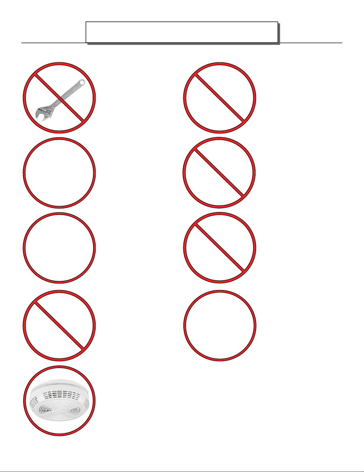
Never try to repair or replace
any part of this appliance
unless instructions are given
in this manual. All other work
must be done by a trained
technician.
Allow the appliance to cool
down before carrying out any
maintenance or cleaning.
Maintain the door and glass
seal and keep them in good
condition. A leaking door seal
will shorten burn times and
may harm the combustor.
Avoid placing wood against
the glass when loading. Do
not slam the door or strike the
glass.
Do not throw this manual
away. This manual has
important operating and
maintenance instructions that
you will need at a later time.
Always follow the instructions
in this manual.
AF25
Do not place clothing or other
fl ammable items on or near
this appliance.
DO NOT OVER FIRE THIS
HEATER. Attempts to
achieve heat output rates
that exceed heater design
specifi cations can result in
permanent damage to the
heater and to the catalytic
combustor. Over fi ring the
appliance may cause a house
fi re. Never burn the appliance
so hot that the appliance or
chimney connector begins to
glow.
Do not use a grate or other
device to elevate the fi re off of
the fi rebox fl oor. Burn the fi re
directly on the bricks.
Ashes should be placed in a
steel container with a tightly
fi tting lid and moved outdoors
immediately. If the ashes are
disposed of by burial in soil or
otherwise locally dispersed,
they should be retained in
the closed container until
all cinders have thoroughly
cooled. Other waste shall not
be placed in this container.
It is required in some jurisdictions to install smoke and carbon monoxide detectors where
heaters are installed. Install at least one smoke detector on each fl oor of your home to
ensure your safety. It should be located away from the wood appliance and close to the
sleeping areas. Locating a smoke detector too close to a wood appliance can cause the
smoke detector alarm to sound if a puff of smoke is emitted while the wood appliance door
is open during reloading. Follow the smoke detector manufacturers placement, installation,
and maintenance instructions.
180-AF25 v1.07 October 2, 2018
Page 11
AF25
SAFETY PRECAUTIONS
This appliance is designed and approved for burning cord wood only. DO NOT burn trash,
garbage; artifi cial or paper logs; gift wrappings; coal; lighter fl uids; chemical cleaners;
chemical starters; treated or painted wood; salt water driftwood or foil-backed paper such
as gum wrappers or cigarette packages; lawn clippings or yard waste; materials containing
rubber (including tires), plastic, asbestos; waste petroleum products, paints or paint
thinners, or asphalt products; construction or demolition debris; railroad ties or pressuretreated wood; manure or animal remains; unseasoned wood or paper products, cardboard,
plywood, or particleboard. The prohibition against burning these materials does not prohibit
the use of fi re starters made from paper, cardboard, saw dust, wax and similar substances
for the purpose of starting a fi re in an aff ected wood heater. Burning these materials may
result in the release of toxic fumes or render the heater ineff ective and cause smoke.
Burn natural wood only. It will void all warranties and safety listings and may damage the
combustor.
Do not use chemicals or fl uids
Never burn the appliance
with the loading door open.
Leaving the door cracked
open may damage the
combustor.
Never block free airfl ow
through vents on this
appliance.
HOT WHILE IN OPERATION.
KEEP CHILDREN,
CLOTHING AND FURNITURE
AWAY.
CONTACT MAY CAUSE SKIN
BURNS.
Do not touch the appliance
when it is hot and educate all
children of the danger of a
high temperature appliance.
Young children should be
supervised when they are
in the same room as the
appliance.
to start the fi re. Never use
gasoline, gasoline-type lantern
fuel, kerosene, charcoal lighter
fl uid, or similar liquids to start or
‘freshen up’ a fi re in this heater.
Keep all such liquids well away
from the heater while it is in use.
Some fuels could generate
carbon monoxide and are very
dangerous.
Keep furniture, curtains,
wood, paper and other
combustibles a minimum of
48in (1219mm) away from
the front of the appliance.
ALSO, DO NOT STORE
COMBUSTIBLES UNDER
THE APPLIANCE (WOOD,
PAPER etc.).
Page 11
This appliance must be
properly installed to prevent
the possibility of a house
fi re. The instructions must
be strictly adhered to. Do not
use makeshift methods or
compromise in the installation.
180-AF25 v1.07 October 2, 2018
Contact local building offi cials
to obtain a permit and
information on any installation
restriction or inspection
requirements in your area.
Notify your insurance
company as well.
Page 12
Page 12
• BEFORE INSTALLING THIS APPLIANCE, CONTACT THE LOCAL BUILDING OR FIRE OR OTHER
AUTHORITY HAVING JURISDICTION AND FOLLOW THEIR GUIDELINES.
• THIS APPLIANCE MUST BE INSTALLED BY A QUALIFIED INSTALLER. FOLLOW THE
INSTALLATION DIRECTIONS. DO NOT OPERATE WITHOUT FULLY ASSEMBLING ALL
COMPONENTS.
• IF THIS APPLIANCE IS NOT PROPERLY INSTALLED, A HOUSE FIRE MAY RESULT.
• THIS APPLIANCE IS HOT WHEN OPERATED AND CAN CAUSE SEVERE BURNS IF
CONTACTED. CHILDREN AND PETS MUST BE KEPT FROM TOUCHING THE APPLIANCE
WHEN IT IS HOT.
• COMBUSTIBLE MATERIAL SUCH AS FIRE WOOD, WET CLOTHING, ETC. PLACED TOO CLOSE
CAN CATCH FIRE. OBJECTS PLACED IN FRONT OF THE APPLIANCE MUST BE KEPT A
MINIMUM OF 48”(1219 MM) FROM THE FRONT OF THE APPLIANCE.
Blaze King grants no warranty, implied or
stated, for the installation or maintenance of the
appliance and assumes no responsibility of any
consequential damage(s).
INSTALLATION INSTRUCTIONS
AF25
PARTS INCLUDED WITH THE ASHFORD INSERT
1. Poker
2. Manual Kit (w/ warranty cards, fi re starter, labels)
3. Bypass Handle (Z2052)
REQUIRED SHROUD OPTIONS
Z2091 Shroud AF25 29 1/4” Z2093 Shroud AF25 32 1/4”
FLOOR PROTECTION
If the bottom of the appliance is 5” (125 mm) or more above the fl oor level (combustable material) only ember
protection is required (UL 1618 type 1) extending 16” (407 mm) in USA or 18” (458 mm) in Canada in front of
the door and extending 8” to either side of the door opening.
If the bottom of the appliance is at fl oor level (combustable material) or less than 5” (125 mm) above fl oor level,
a layer of non-combustible thermal protection (UL 1618 type 2, where R=1.06 minimum) is required under the
appliance extending 16” (407 mm) in the USA and 18” (458 mm) in Canada.
COMPONENTS REQUIRED
6” stainless steel liner - listed to: UL 1777, ULCS35 OR ULCS640.
180-AF25 v1.07 October 2, 2018
Page 13
AF25
A
B
C
D
E
F
INSTALLATION INSTRUCTIONS
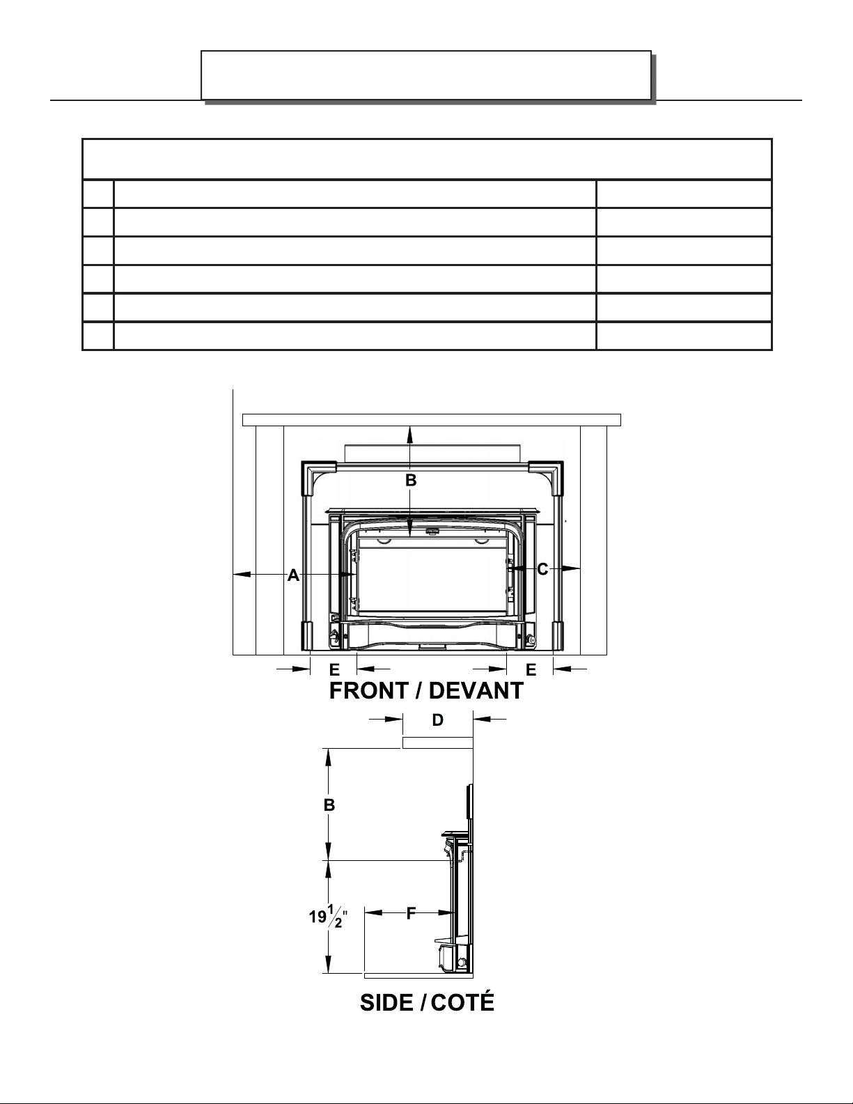
MINIMUM CLEARANCES for AF25
Minimum clearances to combustibles
Measured from fi rebox door fl ange
Side of door fl ange to combustible wall. 13.5" / 343 mm
Top of door fl ange to bottom of mantel and combustible facing. 20" / 508 mm
Side of door fl ange to side of combustible facing. 10" / 254 mm
Mantle width maximum. 12" / 305 mm
Minimum hearth side extension * 8"*
Mimimum hearth front extension 16" USA / 18" CANADA
Page 13
* Measured from each side of the fuel loading and ash removal openings / mesuré de chaque coté de l’ouverture de la porte
de chargement et du tiroir de cendre
180-AF25 v1.07 October 2, 2018
Page 14

Page 14
INSTALLATION INSTRUCTIONS
AF25
COMBUSTION AIR
Ensure adequate combustion air allowing for all other exhausting type appliances in the dwelling (range hoods,
dryers, etc.). In air tight homes and modern constructions, careful considerations must be taken into account
when using a wood burning appliance. Heat recovery ventilators (HRV) systems along with constant running
fan motors in air handlers must be taken into account when balancing the system. Failure to do so may
result in air starvation, smoke spillage and carbon monoxide threats. Consult a HVAC specialist for proper
installation. Ensure adequate combustion air allowing for all other exhausting type appliances in the dwelling
(range hoods, dryers, etc.). In airtight houses it is recommended to install a fresh air inlet into the room where
the appliance is located, to prevent air starvation.
DRAFTING PERFORMANCE
Draft is the force which moves air into the appliance up through the chimney. The amount of draft created by
your chimney depends upon length, off sets, insulating properties, obstructions (such as architectural design,
trees), local geography and other factors.
External forces, such as outdoor temperature, wind, barometric pressure, topography, or factors inside the
home (negative pressure from exhaust fans, chimneys, air infi ltration, etc) may adversely aff ect draft.
Too much draft may cause excessive temperatures in the appliance and may damage the heater. An
uncontrollable burn or excessive temperature indicates excessive draft.
Inadequate draft may cause back puffi ng (spillage) into the room and plugging of the chimney, chimney cap or
spark arrestor screen. Inadequate draft may cause smoke to leak into the room through appliance or chimney
connector joints. Poor draft can also lead to poor heat production and the inability for the combustor to remain
active in lower burn rate settings.
High effi ciency appliances, such as your Blaze King stove, may require some fi ne tuning of your chimney
system in order to maximize performance.
Blaze King cannot be responsible for external forces leading to less than optimal performance.
ROLE OF THE CHIMNEY
Without a proper installed chimney, this appliance will not burn correctly.
The role of the chimney is to pull the proper amount of air into the fi rebox for the purpose of complete
combustion. Incomplete combustion will lead to more smoke and pollution of the outside air. A proper
operating chimney will allow the user to enjoy peak performance at all burn operating levels from low to high.
Blaze King therefore recommends vertical installations with a minimum length of 15’ from appliance top to
chimney cap. In insert applications Blaze King recommends insulated liners into all existing chimneys.
180-AF25 v1.07 October 2, 2018
Page 15
AF25
INSPECT CHIMNEY
Before connecting any wood-burning unit to an existing chimney, inspect the chimney to be sure that it is in
good condition. There must be no cracks or holes. The cross-sectional area can diff er from the fl ue collar as
long as suffi cient draw is maintained and local codes and jurisdiction are observed.. A proper chimney is crucial
for safe, satisfactory operation of any wood heating system. Relining or rebuilding may be necessary to make
the chimney safe, effi cient, and in conformity with local codes.
Masonry Chimneys that have a very large cross-section , particularly exterior chimneys, may experience poor
draft and may require relining to reduce the cross-section-and provide a proper draft. This is also an ideal time
to clean the existing chimney. For peak effi ciency, a clean chimney fl ue is essential. A qualifi ed professional
chimney sweep can perform both inspection and cleaning. If you choose to clean your own chimney use the
proper tools. Homemade cleaners may damage your chimney.
PLANNING STOVE PLACEMENT
NOTE: THIS INSERT IS SUITABLE FOR INSTALLATION IN EITHER:
A FACTORY BUILT FIREPLACE LISTED TO UL 127 OR ULC S20
A CODE-APPROVED MASONRY CHIMNEY WITH A FLUE LINER. MANDATORY in CANADA, recommended
in USA.
INSTALLATION INSTRUCTIONS
Page 15
Check the fi replace and insert dimensions to ensure the insert will fi t properly. While planning your installation
keep in mind the required clearances as shown on the stove label.
Plan ahead to be certain that furniture will have ample clearance, and that drapes and curtains cannot come in
contact with the room heater. Refer to the approval label on the stove for correct clearances to combustibles.
This stove must be connected to a chimney. It must be vented to the outside.
NEVER PERMIT YOUR STOVE TO VENTILATE INTO ANY ROOM IN THE BUILDING
Consult the stove label to ensure that you install your stove the proper minimum distances from combustible
materials.
Minimum fi replace opening size is 29” x 22” x 19” (W x H x D)
Electrical Power - The stove is equipped with a fan assembly with a 10-foot electrical cord. Do not route the
cord in front of the stove.
THE FIREPLACE IS SHIPPED WITH THE FRONT CAST ASSEMBLY ATTACHED, THIS ADDS
CONSIDERABLE WEIGHT TO THE STOVE, IT ALSO MAKES THE FIREPLACE WIDER.
SHOULD THE FIREPLACE BE TOO HEAVY OR TOO WIDE TO POSITION, IT IS POSSIBLE
TO REMOVE THE FRONT CAST ASSEMBLY TEMPORARILY, THEN REATTACH WHEN THE
FIREBOX IS ALMOST IN POSITION (SEE “FRONT CAST REMOVAL” ON THE NEXT PAGE).
IF NOT REMOVING THE FRONT CAST ASSEMBLY GO TO STEP 1 OF “STOVE ASSEMBLY”.
180-AF25 v1.07 October 2, 2018
Page 16
Page 16
FRONT CAST REMOVAL
1. Disconnect the two rheostat wires from the
front cast assembly. Open the loading door.
Remove eight 1/4-20 nuts from top brackets
and side posts with a 7/16” wrench. Remove
two 10-24 nuts from analog cat therm using
a 3/8” wrench. Slide the cast assembly away
from fi rebox and set aside. Position fi rebox in
front of fi replace opening (Fig. 1). To re-attach
the front cast assembly simply reverse these
steps.
STOVE ASSEMBLY
Flue collar assembly removal
1. Position stove in front of fi replace opening, and
open loading door.
2. Remove the two nuts from inside the fi rebox
that hold fl ue collar assembly in place, use a
9/16” wrench (Fig. 2). Ensure gasket is still
fully intact and adhered to fl ue collar base. Set
fl ue collar assembly aside until “fl ue collar
preparation” later in installation.
INSTALLATION INSTRUCTIONS
AF25
Fig. 1
Thermostat rod installation
3. Ensure fans have not shifted during transport
and are in correct position.
4. Slide thermostat rod in from side of cast, then
align machined faces of rods and secure with
the set collar. (Fig. 3)
Fig. 2
Fig. 3
180-AF25 v1.07 October 2, 2018
Page 17
AF25
5. Determine which side the nearest electrical
outlet is then feed electrical cable through lower
back corner of the cast facing on that side.
Ensure wiring is tucked above the protruding
fl anges of the front cover. (Fig. 4)
INSTALLATION INSTRUCTIONS
NOTE: IF POWER CORD IS RUN
THROUGH THE RIGHT SIDE OPENING
THEN ENSURE THAT THE EXCESS WIRE
IS SECURED WITH A ZIP TIE TO AVOID
POTENTIAL INTERFERENCE WITH FAN.
Page 17
6. Slide shroud down behind front cast and fasten
to fi rebox with seven #8 x 1/2 screws. The
bypass door handle bracket can be screwed to
either side of the shroud. (Fig. 5)
7. Position stove in fi replace opening. If required,
use the four leg leveler bolts to level the fi rebox.
(Fig. 6)
Fig. 4
BYPASS HANDLE
BRACKET
Fig. 5
FRONT COVER
Fig. 6
180-AF25 v1.07 October 2, 2018
Page 18
Page 18
8. Fasten lower cast cover to cast face using a
5/32” alan key, two screws. (Fig. 7)
Flue Collar Preparation
1. For ease of install; once chimney piping is
completely installed and attached to the
provided fl ue collar, leave fl ue collar hanging
roughly 2 feet above the fl oor of the fi replace.
This will enable unit to be pushed back into
the fi replace opening without interference and
allow for an easy grab through the bypass door
opening to install. Ensure 1/4” gasket is intact
on the bottom of the fl ue collar assembly before
installation. (Fig. 8)
INSTALLATION INSTRUCTIONS
AF25
Fig. 7
#Z2015
FLUE COLLAR
BASE
160.2055
1/4” GASKET
Fig. 8
180-AF25 v1.07 October 2, 2018
Page 19
AF25
NUTS
INSTALLATION INSTRUCTIONS
NOTE: TO REMOVE THE INSERT FOR
THE PURPOSE OF INSPECTING THE
FIREPLACE INSERT AND FIREPLACE,
DO STEPS 1 to 4 IN REVERSE.
#Z2015
FLUE COLLAR
ASSEMBLY
Page 19
#2055
#2079
1/4” GASKET
BYPASS SHEILD
Fig. 9
Flue Collar Installation
1. Open the loading door and remove the bypass sheild from the bypass opening using a 7/16” wrench, set
parts aside.
2. Open the bypass door then reach up through bypass opening to grab fl ue collar assembly. Pull down to
align bolts with through holes in fi rebox rear then pull forward.
NOTE: ENSURE TOP SURFACE IS MATING WITH FIREBOX TOP. THE GASKET OF THE FLUE
COLLAR NEEDS TO BE IN CONTACT WITH THE FIREBOX ON ALL SIDES. FEEL THE AREA
WHERE THE FLUE COLLAR MAKES CONTACT WITH THE FIREBOX, IF THERE IS A GAP, THE FLUE
COLLAR IS NOT SEATED PROPERLY AND NEEDS TO BE REALIGNED.
3. Once sealed, fasten fl ue collar assembly to fi rebox using a 9/16” wrench, and the supplied stainless steel
nuts (Fig. 9). Tighten fl ue adapter bolts evenly so a tight seal is maintained.
4. Re-attach the bypass sheild using a 7/16” wrench.
180-AF25 v1.07 October 2, 2018
Page 20
Page 20
CHIMNEY
In Canada and in the USA: This insert may be installed into a compliant factory built fi replace providing the
chimney is lined from the outlet of the insert to the top of the chimney using an insulated stainless steel liner
which meets UL-127 or ULC-S610. The liner must be securely attached to both the insert and the chimney
top. In both Canada and the U.S.A. the existing fi replace damper must be secured in the open position. If
this is not possible the damper must be removed. Any openings between the masonry of the fi replace and the
facing masonry must be sealed.
INSTALLATION INSTRUCTIONS
FACTORY-BUILT FIREPLACE
AF25
THE FIREPLACE CANNOT BE MODIFIED IN ANY WAY TO FIT THE INSERT
GENERAL CHIMNEY INSTALLATION
If this stove and its chimney components are not properly installed, a house fi re may result. For your safety,
follow the installation directions. Contact local building or fi re offi cials about restrictions and installation
requirements in your area.
We recommend that the inside your chimney be at least the same diameter as the fl ue of your stove. If you
plan to use an existing masonry chimney, be sure it is free of cracks and loose joints. Gases traveling through
a chimney can reach extremely high temperatures. Cracks or loose mortar can allow hot gases to reach the
wood portion of the structure surrounding the chimney. These toxic gases can also re-enter the house through
cracks and small holes in the chimney, or cause back-puffi ng which will result in excessive smoking. Be on
the safe side and have your chimney inspected by a certifi ed chimney sweep. A 6 inch insulated stainless
steel chimney liner with a direct connection to the stove is recommended for masonry chimney installations. A
chimney must extend at least three feet above the highest point where it passes through the roof and at least
two feet higher than any portion of the building within ten feet of the chimney. Smoke travels up the chimney
in a circular, spiraling motion. A 6 inch round insulated stainless steel liner allows the smoke to travel with less
resistance. A rough masonry chimney without a good smooth liner can result in the rapid build up creosote.
• BEFORE YOU BEGIN CHECK ALL LOCAL CODES AND REGULATIONS REGARDING
YOUR INSTALLATION.
• DO NOT CONNECT THIS UNIT TO A CHIMNEY FLUE SERVING ANOTHER APPLIANCE
180-AF25 v1.07 October 2, 2018
Page 21
AF25
YOUR FIRST FIRE!
The following pages contain information on the major components and operation of your heater. Please
take time to read about them as it will give you a better understanding of how your appliance works. This
understanding will help you to operate your appliance properly thus will extend the life of your appliance and
allow you to get the highest effi ciencies from your heater.
THERMOSTAT
The thermostat knob is located on the lower left side of the front cast assembly. It controls the burn rate of the
stove. Any thermostat position between LOW(thin line) and HIGH(wide line) will produce the desired clean
burning characteristics. However, since each installation is diff erent, you may fi nd it necessary to operate
the thermostat to suit your situation. A HIGH(wide line) thermostat setting will produce maximum heat which
is more than suitable for heating the average size home. All adjustments to the thermostat should be done
gradually. When you fi rst light the stove set the thermostat to HIGH(wide line) setting for 20-30 minutes, or
until the fi re is well established. Once the fi re is
established turn the thermostat to MED(middle
of line) for 5 minutes and then to a LOW(thin
line) setting or the desired setting. Too rapid
an adjustment may cause the stove to operate
improperly. The most common mistake new
owners make is continually adjusting the
thermostat.
OPERATING INSTRUCTIONS
Page 21
BYPASS
Most catalytic wood burning appliances have a bypass device to allow the smoke from the fi re to temporarily
bypass, or go around, the catalytic combustor. The bypass door is located inside the fi rebox at the top of
the stove. The bypass is a steel plate door, and is controlled by the bypass rod and latch above the door in
the middle of the stove. Use the bypass handle on the side of the latch (Fig. 10) to pull the rod out, then the
bypass is open, use the bypass handle on the center of the latch to push the rod in, then the bypass is closed
(Fig. 11). The bypass handle is hung from a bracket on either the left or right side of the shroud.
NEVER OPEN THE LOADING DOOR WITHOUT OPENING THE BYPASS DOOR
DO NOT TOUCH THE BYPASS LATCH DIRECTLY, ALWAYS USE THE BYPASS HANDLE. DURING
OPERATION THE BYPASS LATCH GETS VERY HOT AND CAN CAUSE SERIOUS BURNS.
Fig. 10 Fig. 11
180-AF25 v1.07 October 2, 2018
Page 22
Page 22
CATALYTIC THERMOMETER
The catalytic thermometer is located in the lower left-hand corner
of the cast surround. (Fig. 12) It’s purpose is to show you if the
combustor is active. Always operate the stove when the needle is in
the active red zone. When the combustor is not active the stove will
emit smoke and will not be effi cient. For an accurate reading, turn
fans off for approximately 10 minutes and then read the thermometer.
SELECTING WOOD
• THIS APPLIANCE IS DESIGNED TO BURN NATURAL WOOD ONLY. DO NOT BURN TREATED
WOOD, COAL, CHARCOAL, COLORED PAPER, CARDBOARD, SOLVENTS OR GARBAGE.
• HIGHER EFFICIENCIES AND LOWER EMISSIONS WILL GENERALLY RESULT WHEN BURNING
AIR DRIED SEASONED WOODS, AS COMPARED TO WET, GREEN OR FRESHLY CUT WOODS.
• BURNING WET UNSEASONED WOOD CAN CAUSE EXCESSIVE CREOSOTE ACCUMULATION.
WHEN IGNITED IT CAN CAUSE A CHIMNEY FIRE THAT MAY RESULT IN A SERIOUS HOUSE FIRE.
OPERATING INSTRUCTIONS
AF25
Use dry seasoned wood, split and stacked and protected from rain for at least 24 months with a moisture
content of 20% or lower. It takes a great deal of energy to evaporate the moisture contained in green wood
and that energy will not be heating your house. Also, green or wet wood will greatly increase creosote
problems. The only accurate method to determine moisture content in wood is to use a moisture meter.
Never burn salt-water driftwood. It is very corrosive and will damage the fi rebox. Burning salty wood also
voids the warranty.
This controlled combustion fi rebox has been designed for high effi ciency and long burn times.
The proper time to add more wood is when the last charge has been reduced to a glowing charcoal bed
and while the catalytic thermometer is still active range. There will be very little smoke at this stage in the
burn cycle.
Both hardwood and softwood burn equally well in this appliance but hardwood, which is more dense, will weigh
more per cord and burn a little slower and longer. Firewood should be split and stacked in a manner that air
can get to all parts of it and covered in early spring to be ready for burning that fall.
The only accurate way to determine wood moisture is to purchase a moisture meter.
• NEVER START A FIRE UNLESS ALL BRICKS ARE CORRECTLY PLACED INSIDE THE FIREBOX.
CHECK THE INSTALLATION INSTRUCTIONS CAREFULLY.
• ALWAYS OPEN THE BYPASS DOOR BEFORE OPENING THE LOADING DOOR.
• ONCE THE LOADING DOOR IS CLOSED, CLOSE THE BYPASS DOOR DIRECTLY AFTER THE
CATALYTIC THERMOMETER NEEDLE IS IN THE ACTIVE ZONE.
180-AF25 v1.07 October 2, 2018
Page 23
AF25
HOW TO USE MOISTURE METERS
1. Take a random selection of around 3-4 logs per
cubic yard or cubic meter.
2. Split each log down the middle.
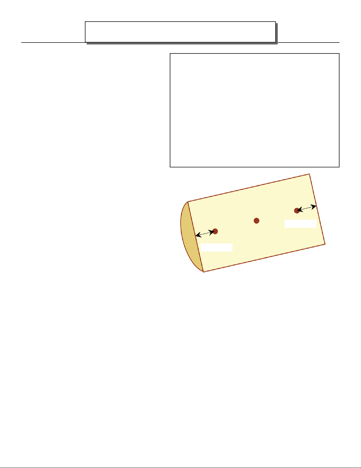
3. In the center of log push pins of meter along
grain - three measurements are taken on the
freshly split surface: 2” or 5 cm in from each
end of the log and in the middle of the split
surface with suffi cient contact (see fi gure).
4. Do this to all the logs and take an average of
the readings (this will be only an approximate
indication but a good guide).
OPERATING INSTRUCTIONS
Page 23
2” / 5 cm
2” / 5 cm
EFFICIENCY
Effi ciency was determined using the method outlined in B415.1-10 test method. It is represented by the Higher
Heating Value (HHV) as the fuel used during testing contains between 19% - 25% water moisture included in
the total calculated fuel weight. (Other test methods such as LHV or Low Heating Value, do not take the water
moisture into account).
Annual Fuel Utilization Effi ciency (AFUE) attempts to represent the actual, season long, average effi ciency of
an appliance. HHV is the actual, calculated average effi ciency obtained under test conditions. Using correctly
seasoned wood is important when trying to gain effi ciency. The more seasoned (dry) the wood, the higher the
effi ciency (less energy wasted on eliminating moisture during combustion). Operating your Blaze King at lower
settings will result in higher effi ciencies as the fuel will undergo a more complete combustion.
180-AF25 v1.07 October 2, 2018
Page 24

Page 24
LIGHTING THE FIRE
NOTE: As you heat up the stove for the fi rst time, the paint will go through a curing process and will give off an odor. To
minimize the inconvenience, burn the stove at a low temperature setting for several hours. It is advisable to open a door
or window until the odor dissipates. You may also notice a change in color as the paint cures, this is normal and will
appear uniform after subsequent fi rings.
1. DO NOT USE A GRATE. BUILD THE FIRE DIRECTLY ON THE BRICK IN THE BOTTOM OF THE APPLIANCE.
2. Set the thermostat to HIGH (maximum) position and turn the fan OFF.
3. Open BOTH the loading door and the bypass door (bypass latch / rod pulled out using bypass handle).
4. Place 10-20 balls of non-glossy paper on the fl oor of the fi rebox, or use a Blaze King fi re starter puck, and then
stack 8-10 lbs of kindling on top of the paper in a crisscross fashion. Be sure to space out the kindling to allow air
to fl ow throughout the fi rebox.
5. Light the balls of paper, or starter puck, and leave the loading door cracked at least 2” to allow the kindling to fully
ignite. This should take approximately 5 minutes. DO NOT LEAVE THE APPLIANCE UNATTENDED.
6. Once the kindling load is fully engulfed, latch the loading door shut BUT keep the bypass door open in order
to get the catalytic combustor up to operating temperature. This is signifi ed by the needle on the catalytic
thermometer moving towards the red “active” zone. This should take no longer than 10 minutes.
7. After 10 minutes and/or once the needle on the catalytic thermometer is in the red “active” zone, close the bypass
door (push the bypass latch / rod in using the bypass handle). LEAVE THE THERMOSTAT ON HIGH.
8. Let the kindling load burn down to small chunks of wood in order to build a 2-3” thick coal bed. This should take
15-25 minutes of continuous burning on HIGH.
9. While waiting for the kindling load to burn down, PREP YOUR MAIN FIREWOOD LOAD. The ideal wood load
for this unit consists of: 3-4 pieces cut to 16” for the bottom row (to be placed into the unit in a front to back
orientation) and 1-2 pieces cut to 18-20” for the top row (to be placed into the unit in a side to side orientation).
The main load should weigh 20lb – 40lb (will vary based on wood species used).
10. Once satisfi ed that a suitable coal bed can be achieved, OPEN THE BYPASS DOOR AND THEN THE LOADING
DOOR and stir up the kindling to form the coal bed. Ensure it is evenly distributed over the entire fi rebox fl oor.
11. With both the loading door and bypass door still open, insert your main fi rewood load (see step 9 for ideal
orientation). Once loaded, CLOSE YOUR LOADING DOOR AND THEN YOUR BYPASS DOOR IMMEDIATELY.
12. Let the appliance burn with the thermostat set to HIGH for 10 – 20 minutes or until the fi re is well established.
Turning the thermostat down too soon could cause the fi re to go out.
13. Once satisfi ed that the fi re is fully established, the thermostat can be adjusted down to the desired heat output
setting.
14. The fan can be turned on once the appliance is hot or 20-30 minutes after the initial loading period.
OPERATING INSTRUCTIONS
AF25
It is good burning practice to burn the stove on HIGH for 20 to 30 minutes after every refuelling, this will help to condition
the wood load for optimum combustion. The temperature in the stove and the gases entering the combustor must be
raised to at least 500° (indicated by the thermometer needle in the active red zone) for catalytic activity to be initiated.
During the start-up of a cold stove, a high fi re must be maintained for at least 20-30 minutes. This ensures that the stove,
catalyst, and fuel are all stabilized at proper operating temperatures. Even though it is possible for fl ue gas temperatures
to reach 600° within 5 minutes of a fi re being started. If the fi re is allowed to die down immediately (thermostat set to a
LOW setting too soon), it may go out or the combustor may stop working, indicated by the thermometer needle being in
the inactive zone. Once the combustor starts working, heat generated in it, by burning the exhaust smoke, will keep it
working.
Probably the least understood requirement in maintaining a good fi re is that of establishing a good base of coals or
embers. A good bed of hot coals or embers will maintain a more even temperature as well as getting the new load of
wood started easily
King automatic thermostat, the wood will only burn at the rate set on the thermostat. Once the full load is established,
the stove should be left to complete the full burn cycle. This is evident by either a coal bed (ember bed) remaining or the
catalyst’s thermometer hovers just inside the active zone. This procedure will maximize the effi ciency of the combustor as
well as limit chimney emissions and smoke spillage.
180-AF25 v1.07 October 2, 2018
. Put as much fuel into the stove as it will hold. Don’t be afraid to fi ll it completely. With the Blaze
Page 25
AF25
OPERATING INSTRUCTIONS
Page 25
DO NOT USE THE APPLIANCE WITHOUT A COMBUSTOR
RELOADING PROCEDURE (with the catalyst temperature in the active red zone)
1. Have your next load of wood ready before beginning. Turn the thermostat to HIGH and turn the fan off .
Wait 2 minutes for the air fl ow to stabilize.
2. Open the bypass door (bypass latch / rod pulled out using bypass handle) and again wait 2 minutes for the
air fl ow to stabilize.
3. Unlatch the loading door and open just a crack to allow the ambient room air to be introduced to the
fi rebox, this may take a few seconds to stabilize.
4. Slowly open the loading door and proceed to reload the fi rebox. If you experience excessive smoke
spillage, slightly close the loading door to re-establish a draft through the chimney.
5. Once loaded, latch the loading door shut and close the bypass door (push the bypass latch / rod in using
the bypass handle). Let the fi re burn on the HIGH thermostat setting for 20 to 30 minutes OR until the fi re
is very well established. At that point, turn the thermostat down to the desired setting. Keep in mind you
may not see a large amount of fl ame activity in the lower thermostat setting. The thermometer needle will
remain in the active zone indicating that the burn cycle is continuing.
6. Should you burn the stove on a very low setting for extended periods of time, you will begin to see
creosote deposits forming on the glass door. To remove these deposits, simple run the stove on HIGH for
approximately 30 minutes. The HIGH setting will burn off most of the deposits
As every pile of wood is diff erent you will learn, over time, which settings are necessary to achieve the optimal
fi re. This will be based on the type of wood, installation, weather conditions and the desired room temperature.
RELOADING PROCEDURE (with the catalyst temperature still in the inactive zone)
Follow the procedure for “LIGHTING THE FIRE” on the previous page.
180-AF25 v1.07 October 2, 2018
Page 26

Page 26
OPTIMAL THERMOSTAT SETTING
Any thermostat position between LOW and HIGH will produce the desired clean burning characteristics.
However, since each application can vary, you may fi nd it necessary to operate the thermostat to suit your
application. A thermostat setting on HIGH will produce a maximum heat which is more than suitable for
heating the average size home and off er the cleanest door glass.
1. Starting the fi re. Each stove, home, installation, chimney installation, and homeowner combination
works a little diff erently. The fi rst several times you fuel the stove, it may not react as you expect. A
little experimentation may be needed to fi nd the right combination of fuel and thermostat setting to
achieve the maximum effi ciency. This is one of the joys of burning wood. You, the wood burner,
make it work. And you can see what happens as it is working. Be patient, the air / fuel mixture and
temperature must be stabilized before maximum combustion effi ciency can be achieved.
2. As the combustor temperature (as indicated by the thermometer) passes into the active red zone,
further adjustment to achieve the desired room temperature should be made in small increments for the
most eff ective cleaner burning operation. Changes should be made as few times each day as possible.
When the thermostat knob is moved from high to low, more gases are produced, so the combustor has
more fuel; consequently the combustor thermometer may register a higher heat for several hours after
the thermostat is turned down.
3. Keep hot coals active so when you reload the stove you will reduce the time necessary to maintain an
active combustor.
4. The thermostat is set at the factory. DO NOT TAMPER WITH THE THERMOSTAT, this will result in a
malfunctioning thermostat.
OPERATING INSTRUCTIONS
AF25
FAN OPERATION
The fans are located beneath the fi rebox of the stove, it recirculates room air up the back and across the
top. This design allows the air to travel the farthest distance across the hot surfaces resulting in super heated
air, most of which can be felt exiting the top of the stove. The fan should be off until the stove reaches
normal operating temperatures. After approximately 30 minutes, the fan speed adjustment should match the
thermostat control setting, i.e. if your stove is set at medium then your fan should also be set at medium, low—
low, high—high etc. The fan control is on the right-hand side of the lower shroud / ash shelf.
ICE - FORMATION AND PREVENTION
Most of what you see coming from the chimney of a properly operating catalytic appliance is water vapor. In
extremely cold weather - and with some exterior chimneys - this vapor may freeze in the chimney to the point
of actually blocking the chimney and extinguishing the fi re. In such weather, occasionally burn the appliance
for 4 or 5 minutes with the thermostat setting on HIGH to melt any possible ice buildup.
180-AF25 v1.07 October 2, 2018
Page 27

AF25
WOOD BURNING IN THE SHOULDER SEASON
There are things to consider if you decide to light a fi re in the spring and fall or when the outside temperature is
milder, perhaps 55°F to 70°F (13°C to 21°C).
As you light the fi re, with the loading door open, you may notice spillage, this is when a small amount of smoke
comes back into the living space. When your fi re begins to warm the chimney and the draft improves, spillage
is greatly reduced. After a short period of time you can adjust the thermostat to a LOW setting and maintain a
comfortable temperature in your home.
In reducing the thermostat setting you have also reduced the fl ue temperatures and your chimney begins
to cool down. At this time the amount of draft is also decreasing and spillage may occur. The diff erences
between the fl ue temperature and the outdoor air temperatures causes your chimney to draw and vent the
fl ue gasses to the outside. This air movement, sometimes referred to as Stack Eff ect, is also infl uenced by air
density and moisture diff erences. Small temperature diff erences produce less draw in your chimney system
than large temperature diff erences.
General Rules for burning in the shoulder season:
• Run your appliance on high for 30 minutes after start up and reloading.
OPERATING INSTRUCTIONS
Page 27
• Slowly turn the thermostat down to the desired heat setting.
• The heat setting needs to be high enough to keep the thermometer in the active zone.
• If the thermometer does not stay in the active zone turn the thermostat to a higher setting. Wait 15 minutes
then confi rm that the thermometer remains in the active zone. Repeat as needed.
• If your appliance is producing too much heat, build smaller hotter fi res.
• Build smaller hotter fi res on milder days in the spring and fall.
180-AF25 v1.07 October 2, 2018
Page 28

Page 28
It is important to periodically monitor the operation of the catalytic combustor to ensure that it is functioning
properly. A non-functioning combustor will result in a loss of heating effi ciency, and an increase in creosote
and emissions. Following is a list of items that should be checked on a periodic basis:
• Combustors should be visually inspected at least three times during the heating season to determine if
physical degradation has occurred. Actual removal of the combustor is not recommended unless more
detailed inspection is warranted because of decreased performance. Refer to “CATALYTIC COMBUSTOR
TROUBLESHOOTING” on next page.
• This catalytic heater is equipped with a temperature probe to monitor catalyst operation. Properly
functioning combustors typically maintain temperatures in excess of 500°F (indicated by the thermometer
needle in the active zone), and often reach temperatures in excess of 1000°F. If catalyst temperatures
fall below 500°F (indicated by the thermometer needle in the inactive zone), refer to next step and to
“CATALYTIC COMBUSTOR, TESTING” below.
• You can get an indication of whether the catalyst is working by comparing the amount of smoke leaving the
chimney when the smoke is going through the combustor and catalyst light-off has been achieved, to the
amount of smoke leaving the chimney when smoke is not routed through the combustor (bypass mode):
- Light the appliance as per the lighting instructions (see “LIGHTING THE FIRE”). With smoke routed
through the catalyst, go outside and observe the emissions leaving the chimney.
- Open the bypass mechanism, wait approximately 15 minutes, and again observe the emissions leaving
the chimney. Signifi cantly more smoke will be seen when the exhaust is not routed through the combustor
(bypass mode). Some smoke may be visible shortly after you start the fi re and shortly after reloading the
fi re. Allow 20 to 30 minutes for the fi re to stabilize before making observations.
CATALYST MONITORING
AF25
CATALYTIC COMBUSTOR, TESTING
Light the fi re as per the lighting instructions (see LIGHTING THE FIRE). Then set the thermostat knob on a
MED setting. When the fi re is well established (within one to three hours) turn the thermostat knob between
LOW and MED. A properly operating combustor will remain active, and the combustor thermometer will
remain in the “active” zone until the wood load is mostly consumed. A “tired” or “dead” combustor will, with
the thermostat on MED or lower, go out completely, and the thermometer needle will fall into the “inactive”
zone. Repeat this procedure several times over several days (Remember that the combustor thermometer
has a built-in lag of 4-8 minutes.) If, after several test burns, the thermometer will not indicate an “active”
combustor, it may require cleaning or replacement. It is also possible that the thermometer, itself, may not
be reading accurately. Before condemning the combustor, read “THERMOMETER”. If, after cleaning has
been performed, your combustor is still not working you can Contact Blaze King for a replacement combustor.
Please read “REPLACEMENT PARTS” section in this owners’ manual.
CATALYTIC COMBUSTOR, CLEANING
Under certain conditions, ash particles may become attached to the face of the combustor. These may be
seen while the combustor is in the glowing stage, or when the fi re is out. Any deposit on the visible face
of the combustor should be removed. Wait until the fi re is out and the appliance is cold before performing
any cleaning. Brushing the combustor with a soft bristle paint brush will remove some deposits. Passing
a vacuum cleaner wand or brush near the face of the combustor will remove most deposits. (Hot ash in a
vacuum cleaner bag will burn, may melt the vacuum or cause a house fi re. Exercise caution and never clean
the appliance when the appliance or ashes are hot.) Never scrape the combustor with any hard tool or brush.
Never run pipe cleaner through the individual cells of the combustor. This is not needed, and may do more
harm than good. Limit cleaning to the face of the combustor. NOTE: Never remove a combustor without
approved combustor gasket in hand as original gasket will fall apart when removed from appliance.
Remember to re-install the Flame Shield (the perforated plate) in same position it was found.
TIP: A hot fi re will usually prove to be the best method of cleaning the combustor of deposits.
180-AF25 v1.07 October 2, 2018
Page 29
AF25
CATALYST MONITORING
CATALYTIC COMBUSTOR, TROUBLESHOOTING
PROBLEM - CREOSOTE PLUGGING
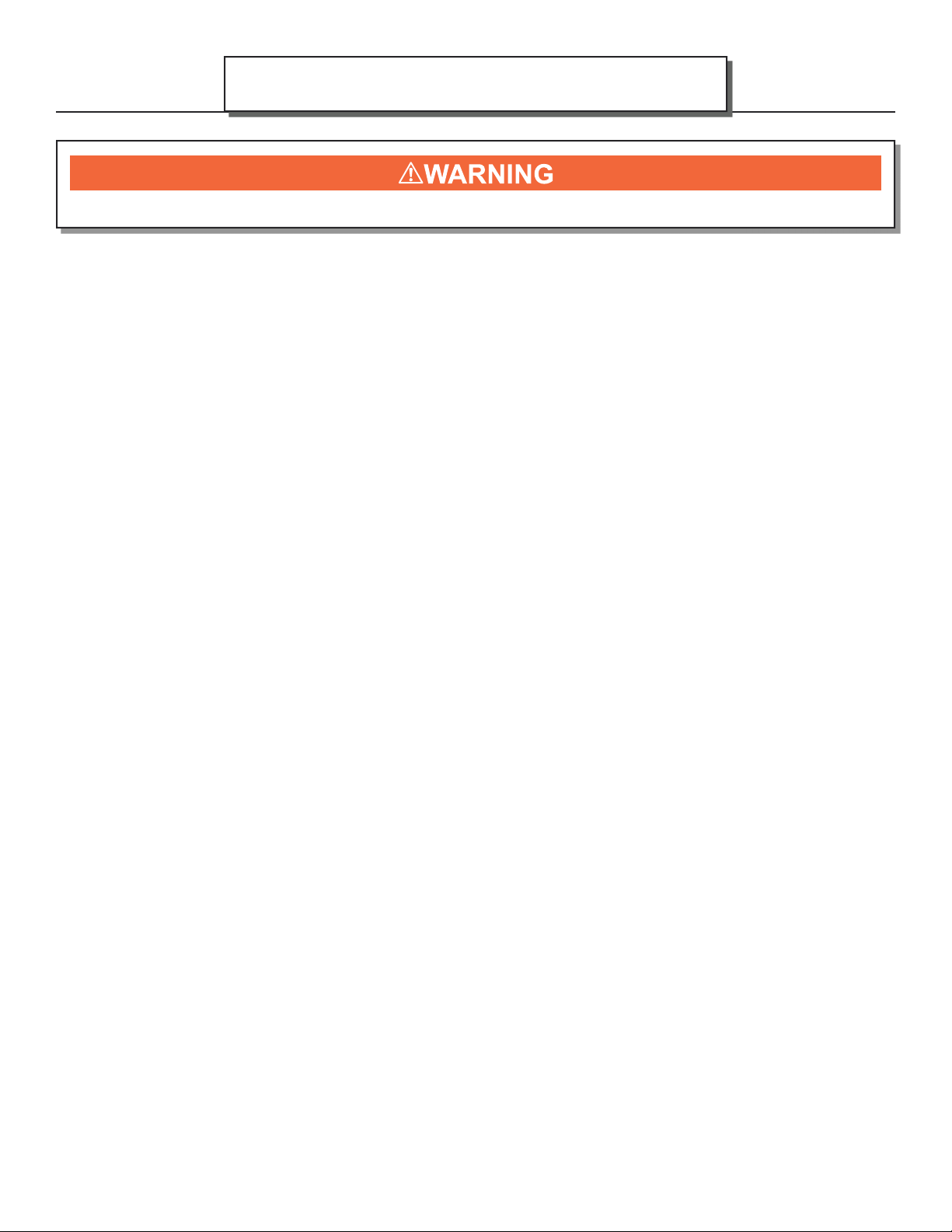
Possible Cause: Burning materials that produce a lot of char and
fl y-ash.
Solution: Do not burn materials such as garbage, gift wrap, or
cardboard.
Possible Cause: Burning wet, pitchy woods or burning large
loads of small diameter wood with the combustor in the operating
position without the thermostat needle in the active zone.
Solution: Burn dry, seasoned wood, don’t engage the bypass
until the temperatures are high enough to initiate light-off
(indicated by the thermostat needle in the active zone).
Possible Cause: Combustor not functioning. If proper burning
procedures have been followed to no avail, the combustor is not
functioning.
Solution: Replace the combustor with a genuine Blaze King
combustor (failure to do so will void your warranty).
Page 29
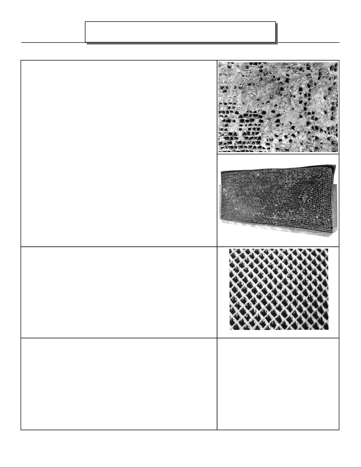
PROBLEM - CATALYST PEELING
Possible Cause: Extreme temperatures (above 1800°F, or
1000°C.) at combustor surface can cause the catalysts to peel.
Over fi ring and fl ame impingement on the combustor are primary
causes. Minor peeling photo shows minor peeling that is normal
and does not aff ect function. Severe peeling photo shows that are
closed or plugged.
Solution: Avoid extreme temperatures and fl ame impingement.
If peeling is severe, remove and replace combustor.
PROBLEM - CATALYST DEACTIVATION
Possible Cause: Burning large quantities of trash, pressure-
treated lumber, or painted woods.
Solution: Burn quality woods available in your area. If you
decide the catalyst has been deactivated, replace combustor with
a genuine Blaze King combustor (failure to do so will void your
warranty).
Minor Peeling
Severe Peeling
180-AF25 v1.07 October 2, 2018
Page 30
Page 30
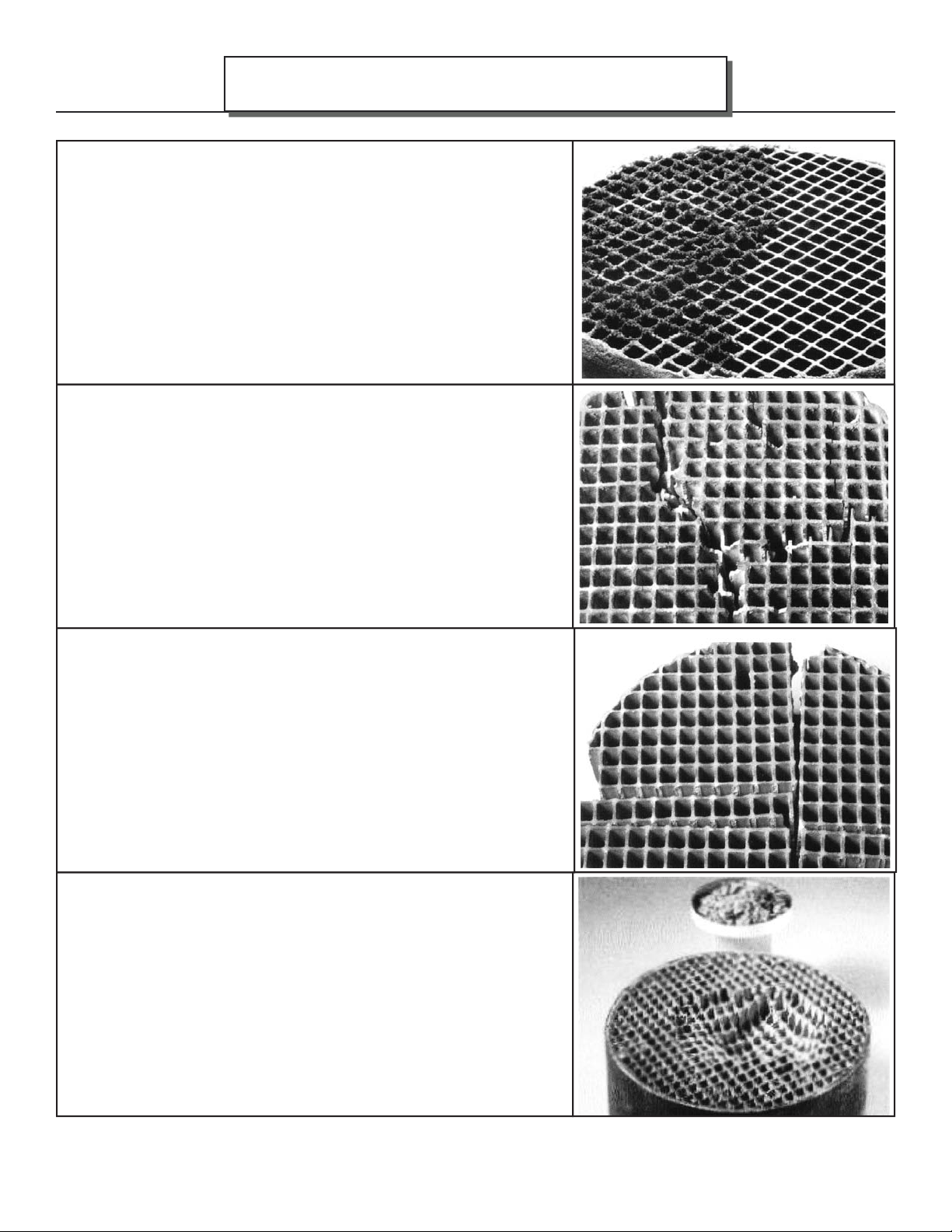
PROBLEM - CATALYST MASKING
(The catalyst is coated with a layer of fl y-ash
or soot which prevents catalytic activity)
Possible Cause: Accumulation of fl y-ash
Solution: Brush cooled combustor with a soft-bristled brush or
vacuum lightly at least once per burning season.
PROBLEM - THERMAL CRACKING
Possible Cause: Normal operation, as long as the combustor
remains intact.
Solution: If cracking causes large pieces to fall out, replace the
combustor.
CATALYST MONITORING
AF25
PROBLEM - MECHANICAL CRACKING
Possible Cause: Mishandling, abuse, or operating without a
properly gasket sealed combustor.
Solution: Handle with care
Possible Cause: Distortion of holding collar.
Solution: Combustor should be held fi rmly in its can. It should
slide easily into and out of the holding collar of the stove. If
severe cracking has resulted in loss of large chunks of combustor,
replace combustor. Also replace any warped stove parts.
PROBLEM - CRUMBLING
Possible Cause: Air leaks
Solution: Inspect door gasket, see “MAINTENANCE cont.” on
page 35.
Possible Cause: High draft
Solution: Maintain draft to manufactured specifi cations.
180-AF25 v1.07 October 2, 2018
Page 31
AF25
CATALYTIC COMBUSTOR, REPLACEMENT
BLAZE KING RECOMMENDS YOUR DEALER PERFORM THIS TASK
The catalytic thermometer on top of the stove should read in the active zone after the stove has been in
operation for several hours. If the thermometer’s indicator needle does not stay in the active zone, even
with a hot fi re, over a 7-10 day period of regular use, the combustor may need replacement or cleaning, see
“CATALYST MONITORING”. If the combustor needs replacing then discontinue use of the appliance until the
combustor is replaced. If the combustor must be examined or replaced contact your Blaze King dealer.
CATALYST MONITORING
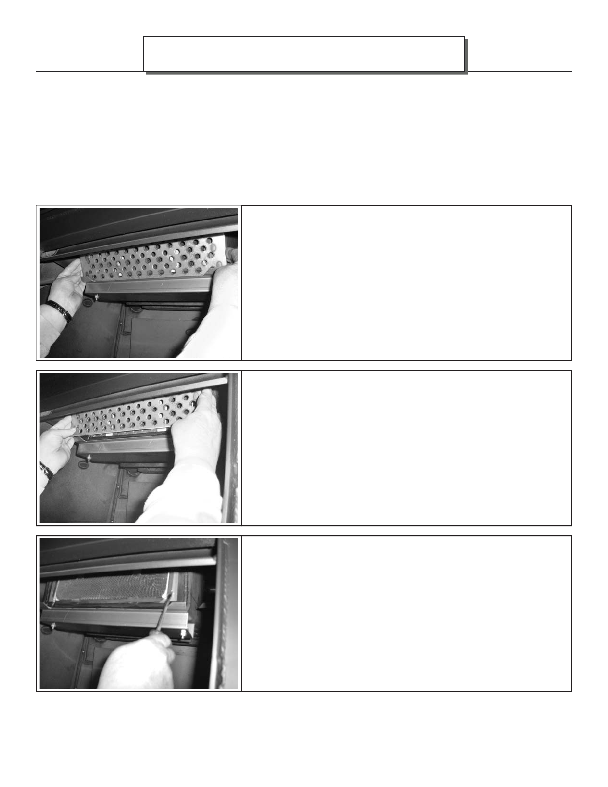
1. The removal of a Blaze King Catalytic combustor requires
a small fl at blade screwdriver or pocket knife. The stove fi re
must be out for at least 12 hours prior to the removal process.
A combustor can reach 1400°F and hold high temperatures for
several hours even after the fi re is out. After waiting 12 hours,
fi rst remove the fl ame shield by simply lifting the shield off the two
tabs at either side. Pay particular attention to orientation as there
is a top and bottom edge to the fl ame shield.
Page 31
2. Once you remove the fl ame shield, you’ll fi nd the combustor.
The honeycomb combustor can be made of diff erent materials
such as cordierite, mulite or even stainless steel. They are all
the same with regard to removal and caution should be taken so
as to not drop or damage the combustor. If your combustor has
never been cleaned according the manufacturers directions, you
may wish to clean the combustor before replacing it with a new
combustor, see “CATALYTIC COMBUSTOR CLEANING”.
3. The combustor has a metal tab across the bottom and on each
side of the combustor. Using a fl at blade screwdriver or pocket
knife blade, slide the blade behind the metal tab and the heavy
steel dome of the stove. The dome is the housing that surrounds
the combustor. Apply slight pressure until the combustor begins
to move forward, about 1/4”. Repeat the process on the opposite
end tab. By working back and forth the combustor will work free
of the dome housing. It is normal for the gasket surrounding the
metal band to fall apart during this process. New combustors are
shipped with a new gasket.
180-AF25 v1.07 October 2, 2018
Page 32
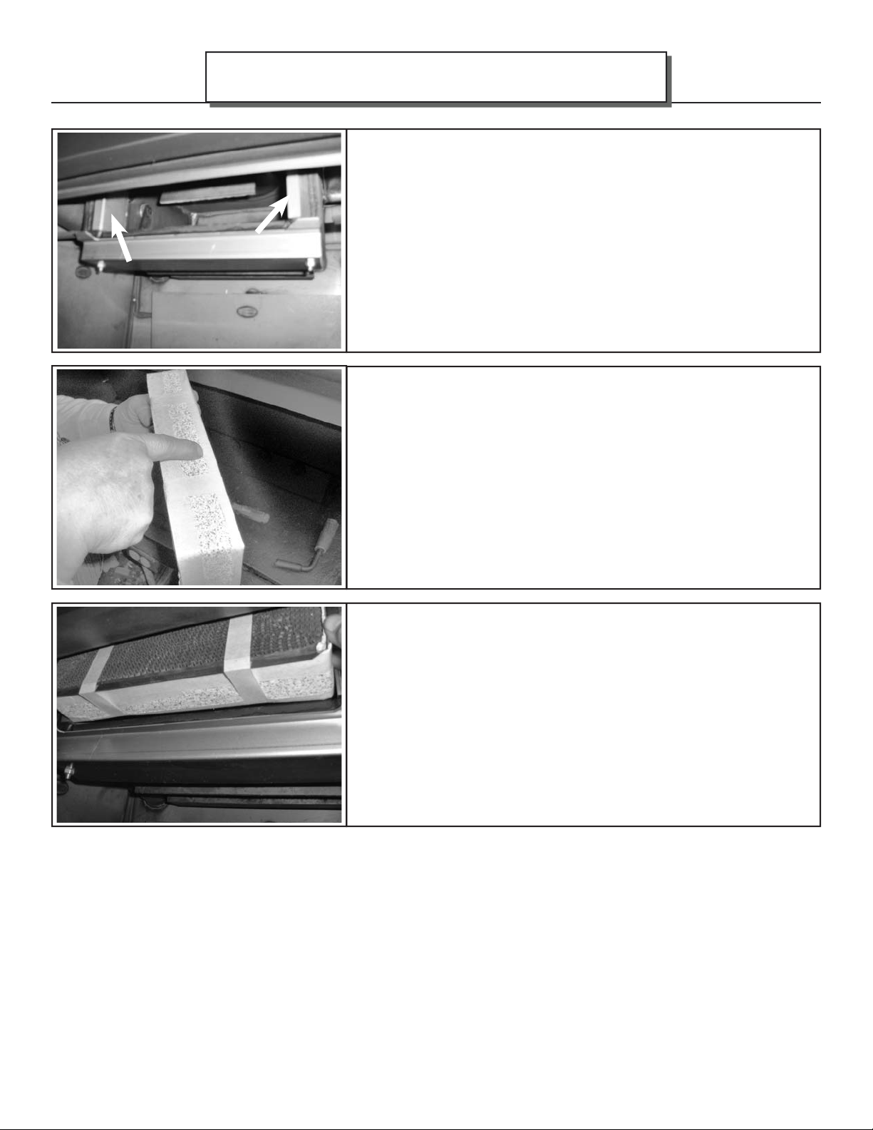
Page 32
CATALYST MONITORING
4. Now that the combustor has been removed you’ll be able to see
one stainless bypass retainer on each side. These can remain in
place and do not need to be removed. These clips are not fi xed in
position and can fall into the fi rebox. Make sure they are in position
before replacing the combustor. Using the same screwdriver or
pocket knife, scrape any old gasket from the surface areas of the
dome. The dome is the housing that surrounds the combustor. If
you clean your existing combustor, you’ll need to order replacement
combustor gasket. It is always a good idea to have a spare
combustor gasket on hand prior to performing any maintenance. If
you purchase a new combustor a new gasket will already be applied
to the combustor.
5. This new combustor already has the gasket installed. Note
the 1” wide masking tape. This tape will help to keep the leading
edge of the gasket from snagging during installation. If you’ve
cleaned your combustor, wrap the combustor gasket as you see
here and use the 1” masking tape around the perimeter front and
rear. During the fi rst fi re the masking tape will burn off and the
combustor gasket will swell providing a tight seal. It is this tight
seal that improves effi ciency and performance. You should never
burn your stove without a combustor gasket installed.
AF25
6. Since the combustor is only 2” deep, there is ample room to lift
the new combustor into place. REMEMBER TO HAVE THE TAB
ACROSS THE BOTTOM EDGE OF THE COMBUSTOR AS IT IS
INSTALLED. Slowly push the combustor in at the top apply even
pressure to the left and right corners. This will allow for a better
view of the bottom edge for the fi nal fi tting. DO NOT FORCE
THE COMBUSTOR INTO THE DOME. TAKE YOUR TIME AND
WORK IT INTO PLACE SLOWLY.
180-AF25 v1.07 October 2, 2018
Page 33
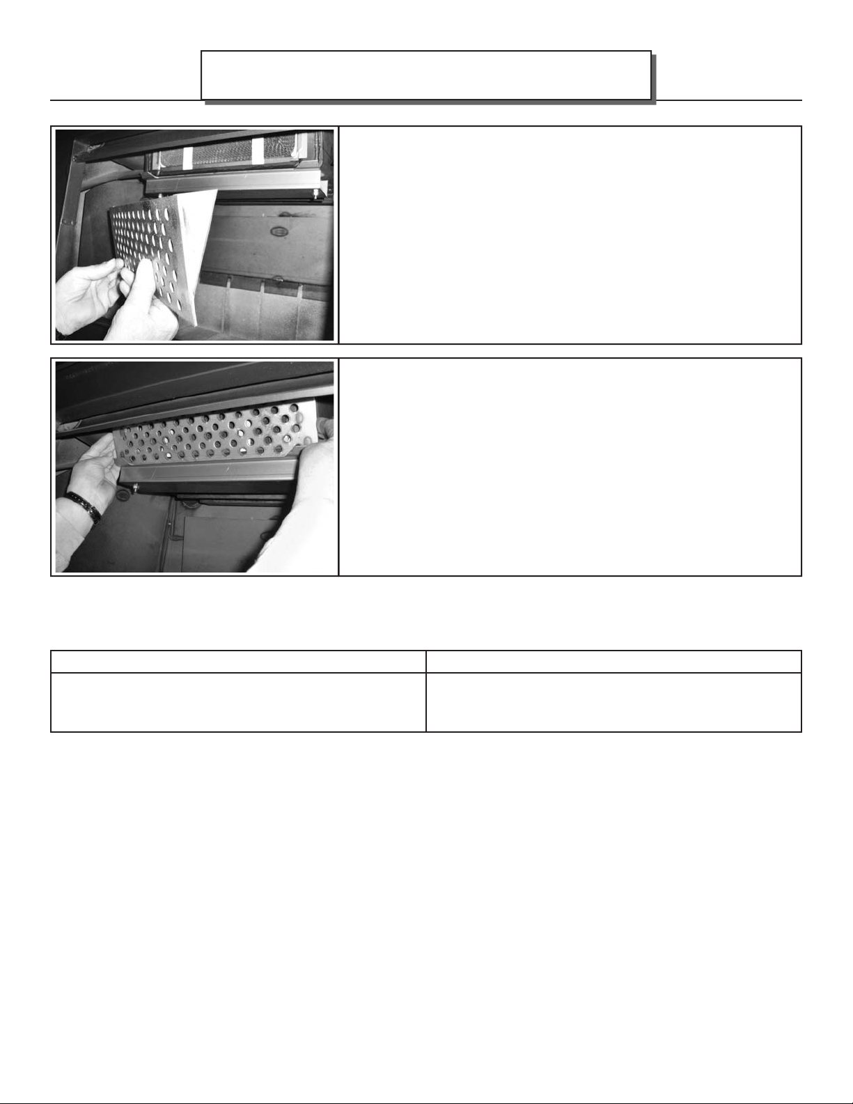
AF25
CATALYST MONITORING
7. Once the combustor is installed completely so that all three
tabs at touching the face of the dome, replace the fl ame shield.
Note the brackets welded to the back fl ame shield are shaped
like a triangle.The point of the triangle should face down when
installed correctly. Never operate your stove without the fl ame
shield in place. The fl ame shield will protect the face of the
combustor against damages from wood when loading and other
possible damages that can occur during the cleaning process.
8. The fl ame shield will rest on the two tabs located on the dome
guard and lean slightly forward. Now that your combustor has
been installed you can relight your stove. You will continue to
receive excellent effi ciency and clean burning for years to come.
A few reminders, never burn anything other than dry, seasoned
cordwood. Burning anything else may contaminate or ruin your
new combustor. Also remember to keep your front loading door
gasket seal properly adjusted, see “LOADING DOOR TENSION
ADJUSTMENT”. Doing so will improve burn times and extend
combustor life span.
Page 33
The combustor supplied with this heater is either a 115.0335 metal combustor. Consult the catalytic combustor
warranty also supplied with this wood heater. Warranty claims should be addressed to:
in Canada in USA
Blaze King Industries / Valley Comfort Systems
Warranty Department, 1290 Commercial Way
Penticton, BC Canada V2A 3H5, Ph: 250-493-7444
Warranty Department, 146A Street
Walla, Walla, Washington 99362, Ph: 509-522-2730
Blaze King Industries
180-AF25 v1.07 October 2, 2018
Page 34
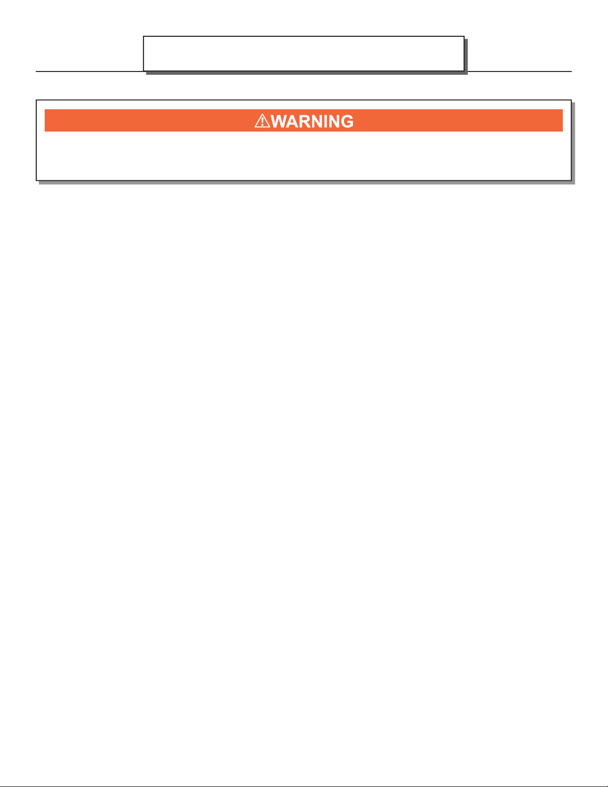
Page 34
RUN-AWAY OR CHIMNEY FIRE
A CHIMNEY FIRE CAN PERMANENTLY DAMAGE YOUR CHIMNEY SYSTEM. THIS DAMAGE CAN
ONLY BE REPAIRED BY REPLACING THE DAMAGED COMPONENT PARTS. CHIMNEY FIRE
DAMAGE IS NOT COVERED BY THE LIMITED WARRANTY.
CAUSES:
1. Using incorrect fuel, or small fuel pieces which would normally be used as kindling.
2. Leaving the door ajar too long and creating extreme temperatures as the air rushes in the open door.
3. Improperly installed or worn gaskets.
4. Creosote build up in the chimney.
SOLUTIONS:
1. Do not burn treated or processed wood, coal, charcoal, colored paper or cardboard.
2. Be careful not to over fi re the appliance by leaving the door open too long after the initial start-up.
3. Replace worn, dried out (infl exible) gaskets.
4. Have your chimney cleaned regularly.
MAINTENANCE
AF25
WHAT TO DO IF A RUN-AWAY OR CHIMNEY FIRE STARTS:
1. Close the draft fully (lowest position) by shutting off thermostat, and make sure fi rebox is closed tightly.
2. Call the local fi re department.
3. Examine the chimney, attic and roof of the house, to see if any part has become hot enough to catch
fi re. If necessary spray with a fi re extinguisher or water from a garden hose.
4. Do not operate the appliance again until you are certain the chimney has not been damaged.
CREOSOTE FORMATION AND REMOVAL
When wood is burned slowly, it produces tar and other organic vapors which combine with expelled moisture
to form creosote. These vapors condense in the relatively cooler chimney fl ue of a slow burning fi re and when
ignited, make an extremely hot fi re. Check your chimney for creosote and soot regularly, until a safe frequency
for cleaning is established. The chimney connector and chimney should be inspected regularly during the
heating season to determine if a creosote build up has occurred. Be aware that the hotter the fi re, the less
creosote is deposited.
If accumulation is excessive, clean the chimney. You may want to call a professional chimney sweep to clean
it. Both the chimney and the appliance have to be cleaned at least once a year or as often as necessary.
Have a clearly understood plan to handle a chimney fi re.
180-AF25 v1.07 October 2, 2018
Page 35
AF25
CHIMNEY MAINTENANCE
The most effi cient method to sweep the chimney is using a hard brush. Brush downwards so soot and
creosote residues will come off the inner surface and fall to the bottom of the chimney where they can be
removed easily.
The chimney must be checked regularly and if creosote has accumulated, it must be removed without delay.
Cleaning on a regular basis should be suffi cient during the coldest months. ENSURE THE BYPASS DOOR
IS OPEN PRIOR TO CLEANING THE CHIMNEY SO THE SOOT AND CREOSOTE FALLS INTO THE
FIREBOX.
Chimney / Flue Inspection: The chimney should be inspected regularly during the heating season for possible
damage and repaired or replaced if necessary.
FLUE COLLAR ADAPTER
If for any reasone the Z2015 fl ue collar assembly is unbolted from the fi rebox than the 1/4” fl ue collar
gasket (#2055) needs to be replaced before reinstallation.
FIRE EXTINGUISHERS AND SMOKE DETECTORS
All homes with a solid fuel burning appliance should have at least one fi re extinguisher in a central location,
known to all, and at least one smoke detector in the room containing the appliance. If it sounds an alarm,
correct the cause but do not de-activate or relocate the smoke detector.
MAINTENANCE
Page 35
ASH REMOVAL
This appliance is required to be cleaned frequently because soot, creosote and ash may accumulate. Wait
until the appliance is fully cooled off before the removal of ashes. ALWAYS REMOVE THE ASH BUCKET
IMMEDIATELY AFTER FILLING. Ashes should be removed any time they come within one inch of the door
opening. It is not necessary or advisable to completely remove all of the ashes when cleaning this appliance.
Wood burns best in a bed of ashes 1/2” thick. Ashes should be placed in a metal container with a tight fi tting
lid. The closed container of ashes should be placed on a noncombustible fl oor or on the ground (outside), well
away from all combustible materials, pending fi nal disposal. If the ashes are disposed of by burial in soil or
otherwise locally dispersed, they should be retained in the closed container until all cinders have thoroughly
cooled. Other waste shall not be placed in this container.
NEVER STORE HOT ASHES IN A GARAGE OR BASEMENT. HOT ASHES WILL GENERATE
CARBON MONOXIDE AND / OR FLAMMABLE GASES. THESE GASES MAY CAUSE
SUFFOCATION AND POSSIBLE DEATH.
180-AF25 v1.07 October 2, 2018
Page 36

Page 36
LOADING DOOR GASKET INSPECTION
Inspect the door gasket for physical deterioration, missing sections or obvious leakage. The appliance front
should make a groove in the gasket material - one side of the groove (toward the inside) will often be dark or
black, and the other side (toward the outside) should be light or white. Dark smudges on the outside of the
groove may indicate an air leak. If the groove is very shallow or missing, or if there is a heavy ash or creosote
deposit along the bottom edge of the gasket, it may need to be replaced. Frayed or broken gasket material,
or a gasket that is hard and unyielding, will also indicate need for replacement. Any time a piece of gasket is
missing or is broken anywhere, the entire gasket must be replaced.
To check the gasket further, wait until the appliance is cooled and insert a piece of paper (a dollar bill will work)
into the door opening and close and latch the door. Obvious resistance should be felt when pulling the paper
out Repeat this check several times around the perimeter of the door.
LOADING DOOR GASKET REPLACEMENT
BLAZE KING RECOMMENDS YOUR DEALER PERFORM THIS TASK
1. If the door gasket is to be replaced, be sure you have Blaze King 7/8” fi ber glass door gasket ready to
re-install, as well as high temperature adhesive. See your Blaze King dealer.
2. Be sure the fi re is out and the stove has cooled down. The door does not have to be removed from the
stove.
3. With a pair of pliers, pull the old door gasket out of the channel and dispose of it.
4. Thoroughly clean out the channel so the new silicone adhesive will adhere and the gasket will fi t
smoothly.
5. Dry fi t the new gasket fi rst to ensure proper fi t. Do not stretch or cut the gasket. Distribute the gasket
evenly around the frame.
6. Run a small bead of a high temperature silicone adhesive along the center of the channel. DO NOT
USE HOUSEHOLD SILICONE CAULKING. High temperature silicone may be obtained from wood
stove dealer.
7. Start the new gasket in the lower right corner. Do not stretch or cut the gasket. Distribute the gasket
evenly around the frame.
8. Allow the adhesive to dry before closing the loading door. The loading door tension may need to be
adjusted, see “LOADING DOOR TENSION ADJUSTMENT” on page 40.
9. Check the fi t of the door gasket. Insert a narrow strip of paper into the door opening and close and
latch the door. Obvious resistance should be felt when pulling the paper out. Repeat this check
several times around the perimeter of the door. If no resistance is felt, adjust door latch catch, see
“LOADING DOOR TENSION ADJUSTMENT” on page 40.
10. A tight sealing door extends the burn times & protects the combustor.
MAINTENANCE
AF25
180-AF25 v1.07 October 2, 2018
Page 37
AF25
BYPASS DOOR GASKET RETAINER REPLACEMENT #Z2022
1. Remove fl ame shield. (see CATALYTIC COMBUSTOR REPLACEMENT step 1)
2. Remove the combustor. (see CATALYTIC COMBUSTOR REPLACEMENT step 2-4)
3. Remove hanging smoke baffl e.
4. Open bypass door (slide it all the way forward) and unthread/remove the 1/4-20 bolt and washer that
fastens the bypass door to the bypass rod bracket. Remove the bypass door through the combustor
opening once detached.
SMOKE
BAFFLE
MAINTENANCE
Page 37
FLAME
SHIELD
COMBUSTOR
BOLT AND
WASHER
BYPASS
ROD
BRACKET
BYPASS
DOOR
180-AF25 v1.07 October 2, 2018
Page 38
Page 38
5. Remove the two 1/4-20 bolts and washers that hold the dome guard in place, be sure to support the
dome guard during this process is it will come loose. Once the dome guard is removed, unthread the
two 1/4-20 coupling nuts that spaced the dome guard from the dome bottom.
MAINTENANCE
COUPLING
NUT
AF25
DOME
BOLT AND
WASHER
6. Remove the twelve remaining 1/4-20 nuts from the dome bottom. Lift the bypass door gasket retainer
assembly upwards (enough to clear the threaded posts from the dome) and remove through the
combustor opening. Once removed, ensure all debris is cleared from the inner surface of the dome.
GUARD
180-AF25 v1.07 October 2, 2018
Page 39
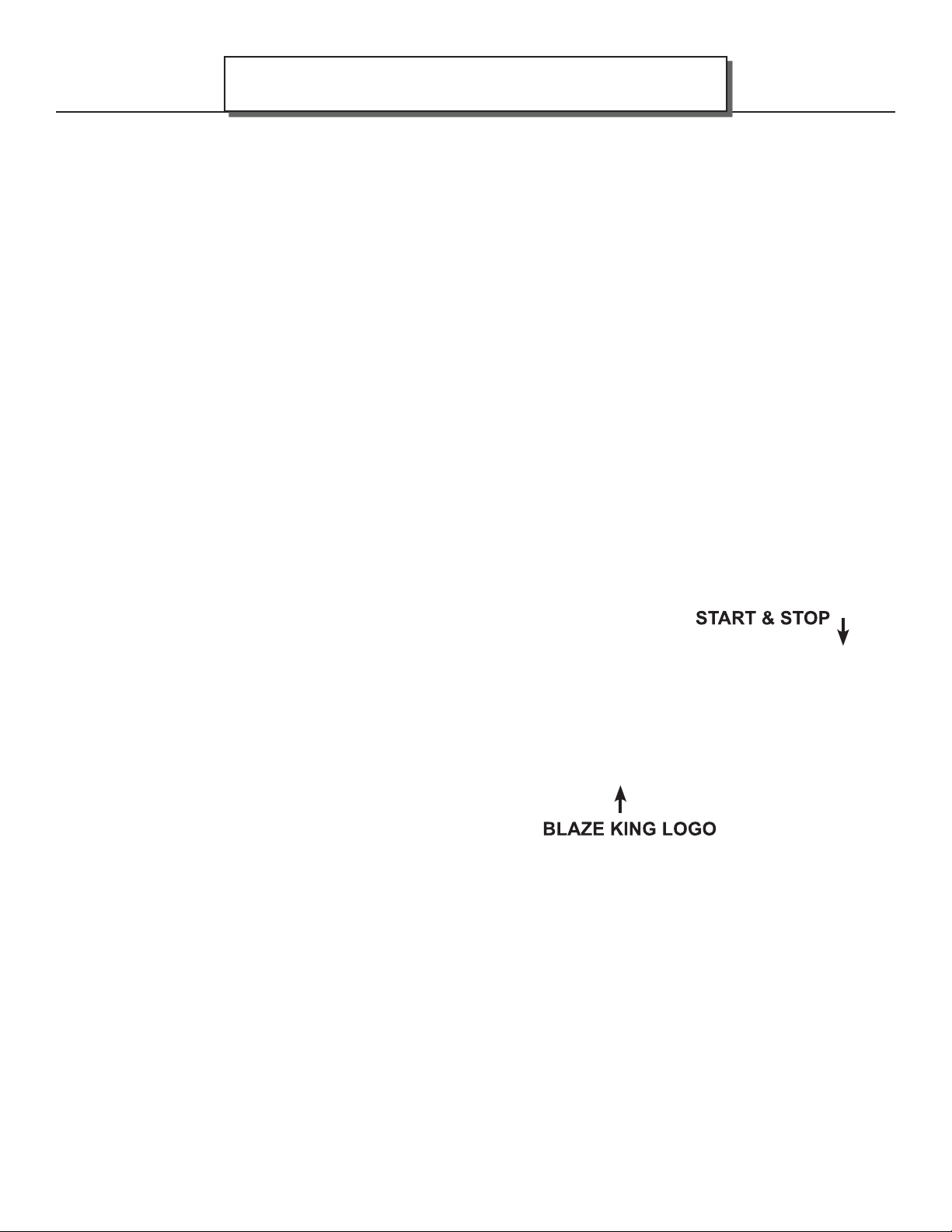
AF25
7. Once the inner dome surface has been cleared, insert the new bypass door gasket retainer assembly
and follow the above instructions in reverse to ensure complete install. Ensure that 1/8” ceramic paper
is in between the gasket retainer assembly and inner dome surface. Also ensure that all nuts are
completely fastened up to the dome bottom. When tightening the 1/4-20 bolt through the bypass door
into the bypass rod bracket, do not over tighten. Simply fi nger tighten the bolt as this allows the bypass
door to move down as the gasket begins to seat after the fi rst few fi res.
8. When reinstalling the combustor, ensure it has been rewrapped with new expanding gasket that was
supplied with the replacement kit. Do not install combustor without gasket.
DOOR GLASS GASKET INSPECTION
When the appliance is cold, hold the glass by placing the palm of each hand on either side of the glass. Press
fi rmly and try to move the glass. If the glass moves the door glass retainers may need to be tightened or the
door glass gasket may need to be replaced.
1. Inspect the door glass gasket. If the gasket is frayed or missing sections replace the gasket.
2. Inspect the glass retainers and ensure the screws holding the retainers in place are tight. Hand tighten
plus 1/4 turn. Do not over tighten.
MAINTENANCE
Page 39
DOOR GLASS GASKET REPLACEMENT
BLAZE KING RECOMMENDS YOUR DEALER PERFORM THIS TASK
1. You will require Blaze King glass gasket and Blaze King door gasket. Please see your Blaze King dealer.
2. Remove the old glass gasket.
3. Starting at the corner opposite of the “Blaze King” logo, carefully wrap the gasket around the edges,
pressing rmly onto the sides of the glass with the
gasket centered on the edge. Finish the wrapping
with a 1/2” overlap. Ensure the thickness of the
gasket remains consistent and uniform.
4. Install glass with the “Blaze King” logo to the lower
le corner of the door. Install the glass retainers with
original fasteners. Ensure the glass is parallel to the
frame and tighten the fasteners evenly.
5. Follow steps on page 38, “LOADING DOOR
GASKET REPLACEMENT”.
DOOR GLASS, REPLACEMENT
Should the door glass become broken and/or damaged, please see your Blaze King dealer for replacement
and installation. Replace only with ceramic glass, 5 mm. thickness. Follow steps 4 and 5 in “DOOR GLASS
GASKET REPLACEMENT” to install the new glass.
DOOR GLASS, CLEANING
The best way to keep the glass clean is to leave the appliance on high burn for a period of time after each
reloading The moisture which is driven from a new load of wood contributes much of the creosote on the
inside of the glass. Removing that moisture at the beginning of the burn cycle helps to keep the glass clean.
Leaving the thermostat on a higher setting for 30 minutes to an hour before turning to low for an overnight burn
will also help. Heavier deposits may require hand cleaning. Manual glass cleaning should be done when the
appliance and glass are cool. DO NOT CLEAN THE GLASS WHILE IT IS HOT. WARNING: Do not use
abrasive cleaners to clean the glass. Use a soft cloth. After using any cleaner, thoroughly rinse the glass
with water to remove any deposits left by the cleaner. Failure to remove all traces of glass cleaner will result in
the glass cleaner residue baking on. This residue may be very diffi cult to remove.
180-AF25 v1.07 October 2, 2018
Page 40
Page 40
LOADING DOOR TENSION ADJUSTMENT
1. Open the door.
2. To tighten the door tension use a 7/16”
wrench to loosen the two nuts on the latch
cover. Slide the latch cover towards the
back of the stove and tighten nuts.(Fig. 13)
Repeat paper test (see “LOADING DOOR
GASKET INSPECTION” on page 35).
MAINTENANCE
Fig. 13
AF25
LOADING DOOR HINGE ADJUSTMENT
1. Open the door to 90°.
2. Hold bottom nuts using a 9/16” wrench.
Use a 1/4” Allen head screwdriver to back
nuts off the bolts. (Fig. 14)
3. Remove the door by lifting up and out.
DO NOT OPERATE THIS WOOD STOVE IF THE
DOOR GASKET IS MISSING OR DAMAGED
DANGEROUS OVER FIRING CAN OCCUR
WHICH CAN DAMAGE THE APPLIANCE OR
IGNITE CREOSOTE IN THE CHIMNEY, POSSIBLY
CAUSING A HOUSE FIRE. IF ANY PART OF THE
WOODSTOVE OR FLUE SYSTEM IS GLOWING THE
STOVE IS BEING OVER FIRED.
Fig. 14
180-AF25 v1.07 October 2, 2018
Page 41
AF25
4. Loosen the four door hinge nuts using
a 7/16” wrench. Slide door hinges in to
tighten door seal and out to loosen door
seal. (Fig. 15)
5. Put door back on using nuts and bolts.
6. Repeat paper test (see “LOADING DOOR
GASKET INSPECTION” on page 35).
MAINTENANCE
Page 41
Fig. 15
FAN ASSEMBLY
Routine maintenance of the fan assembly on the side of the stove is not required. However, should it become
necessary to replace an individual fan or rheostat, contact your local dealer.
THERMOSTAT
This wood heater thermostat has a manufacturer-set minimum low burn rate that must not be altered. It is
against federal regulations to alter this setting or otherwise operate this wood heater in a manner inconsistent
with operating instructions in this manual. If the thermostat malfunctions contact your dealer for replacement
by a qualifi ed installer.
180-AF25 v1.07 October 2, 2018
Page 42
Page 42
Your Blaze King is designed to allow a wide selection of heat output levels. If you begin to lose control of the amount of
heat the stove is emitting, determine the cause early so that major problems may be avoided.
The six major needs of a well-controlled fi re are:
TROUBLESHOOTING
AF25
1. Knowledgeable operator.
2. Adequate air supply.
3. Firewood of good quality and proper size.
4. Catalytic combustor in good condition.
5. Clean chimney, properly sized and installed.
6. Door gasket tight and fi rm.
Considering all of the above, number one is the most important for safe and effi cient operation of any woodstove. Please
study the operation instructions carefully. Consult your BLAZE KING dealer or call the Customer Service Department at
Blaze King in the U.S.A. at 509-522-2730 or in Canada at 250-493-7444 if you have any questions not answered in this
manual.
All of the six above mentioned needs are interrelated. A defi ciency in any one will aff ect all of the others. If you encounter
a problem, determine the source of the problem and then follow-up by checking the other needs as possible contributing
factors.
PROBLEM: Chimney Fire
CAUSE
Act immediately regardless of cause
A er the re is out, have your chimney and ue connector inspected by a certi ed chimney sweep. A damaged masonry chimney
should be repaired or rebuilt. A prefabricated chimney (factory built) that is damaged should be replaced. Any damage to the ue
connector should be corrected before the system is used again.
SOLUTION
Turn the thermostat to lowest setting, check loading door to be
sure it is tightly closed.
Call Fire Department.
Possible causes of a chimney re, and remedies for those causes, can be found further in this section: “Excessive Creosote Formation”,
and “Spots of Creosote Accumulation in Chimney or Flue Connector”.
PROBLEM: Not enough heat.
CAUSE
Green or wet wood.
Not enough fuel in stove.
Obstruction in chimney or cap screen.
Combustor plugged or coated.
Combustor not functioning. See “COMBUSTOR, TESTING”.
Thermostat set too low. Raise thermostat setting.
Thermostat not operating properly. Consult your Blaze King dealer.
Poor draft caused by an oversize fl ue Measure draft with Manometer. See “CHIMNEY DRAFTS”
Strong, gusting winds causing downdraft in
chimney
Tightly sealed house, inadequate air supply. Slightly open a window, near the stove or install an outside air kit.
SOLUTION
Use seasoned wood. Don’t be afraid to FULLY load the stove. A
FULL load of wood won’t burn any hotter than the thermostat is
set.
Remove obstruction. See “COMBUSTOR, TESTING”
See “COMBUSTOR, CLEANING”
If needed, replace combustor, See”“COMBUSTOR, REPLACING”.
Consult your Blaze King dealer or a chimney sweep.
Install wind-resistant chimney cap. Directional caps may not stay
freely rotating. If you have a directional cap, check it frequently.
Reloading too much wood on top of too few coals. Allow a larger bed of coals to build up.
180-AF25 v1.07 October 2, 2018
Page 43
AF25
PROBLEM: Too much heat.
CAUSE
By-Pass door left open.
Thermostat set too high. Lower thermostat setting.
Loading door gasket leaking, admitting excess air
into fi rebox.
Excessive draft in the chimney. Measure draft with a Manometer. See “DRAFTS”. Consult your
Thermostat not operating properly. Consult your Blaze King dealer.
Wood is too small. Use larger pieces.
PROBLEM: One or both fans will not run, or there is no adjustment for fan speed.
CAUSE
Fans mounted improperly.
Fan speed control. Consult your Blaze King dealer for replacement.
PROBLEM: Fans minimum speed too fast or maximum speed too slow.
CAUSE
Fan speed control out of adjustment.
TROUBLESHOOTING
SOLUTION
Close the by-pass door.
Replace door gasket and/or adjust door. See “GASKET
INSPECTION”
Blaze King dealer or a chimney sweep. Install a cap.
SOLUTION
Check that fan blade’s not touch edges of hole.
SOLUTION
Consult your Blaze King Dealer.
Page 43
PROBLEM: Excessive creosote formation in chimney and chimney Connector.
CAUSE
By-pass door left open.
By-pass door not sealing tightly. Inspect by-pass door and seal for warping. Ash or creosote
Improper operation. Check thermostat setting and operating procedures. See
Wood too green or wet. Use seasoned wood. Use a moisture meter to confi rm.
Catalytic combustor not operating properly. Inspect the combustor. See “CATALYTIC COMBUSTOR,
Poor draft caused by an oversize or short fl ue, etc. Measure draft with Manometer. See “DRAFTS”. Consult your
Chimney too cold or poorly insulated. Upgrade chimney system. Consult your Blaze King dealer or a
PROBLEM: Catalytic combustor thermometer (on top of stove) does not go into "Active" zone, or does not stay
there for long. (Fans must be in “off ” position for 10 minutes prior to checking)
CAUSE
Improper operation.
Obstruction in chimney or cap. Clean chimney, remove obstructions.
Faulty combustor thermometer. Replace thermometer and Recheck combustor operating
Wood too green or wet. Use seasoned wood.
SOLUTION
Close by-pass door.
buildup may occur on door or seat. With stove cold scrape and
vacuum area around by-pass. Be sure all mating steel surfaces
are clean and smooth.
“THERMOSTAT & OPTIMAL THERMOSTAT SETTING”
TESTING”
Blaze King dealer or a chimney sweep.
chimney sweep.
SOLUTION
Check thermostat setting and operating procedures. See
“THERMOSTAT & OPTIMAL THERMOSTAT SETTING”
Temperature.
180-AF25 v1.07 October 2, 2018
Page 44
Page 44
Combustor plugged or coated. Clean combustor. See “CATALYTIC COMBUSTOR TESTING”
Combustor not functioning. Check and test combustor. If needed replace combustor. See
Thermostat not operating properly. Consult your blaze King Dealer.
By-pass door leaking or not closing completely. Inspect and clean area around by-pass doors. Adjust or replace
PROBLEM: Spots of creosote accumulation in chimney or chimney connector.
TROUBLESHOOTING
“CATALYTIC COMBUSTOR, REPLACING”
gasket if necessary. Consult your Blaze King Dealer.
AF25
CAUSE
Air leaks in chimney or chimney connector.
CAUTION: a leaking chimney connector is a fi re hazard and demands immediate attention.
Poor draft caused by an oversize fl ue, single wall
pipe, to many elbows, etc.
PROBLEM: Door glass quickly becomes coated with creosote.
CAUSE
Low thermostat setting or lowering the thermostat
setting too far, too quickly.
Poor draft caused by an oversize or short fl ue, etc. Measure draft with Manometer. See “DRAFTS”. Consult your
Obstruction in chimney or cap screen. Remove obstruction. Clean chimney and/or cap screen.
Strong, gusting winds causing downdraft in
chimney.
Tightly sealed house, inadequate air supply. Open a window, slightly, near the stove.
Burning poorly seasoned wet wood, or wood with
high pitch content.
PROBLEM: The combustor temperature cannot be controlled. Turning the thermostat down often makes the
combustor temperature go up.
CAUSE
Turning the thermostat down, particularly in the fi rst half of the burn cycle, causes the fi re to emit more smoke, which is
fuel for the combustor. The combustor temperature therefore climbs for up to several hours. This is normal, and is of no
concern. As long as only the combustor temperature is elevated, there is nothing to worry about.
SOLUTION
Inspect chimney and / or chimney connector. Repair or replace
as necessary. Check to be sure that the chimney connector is
installed correctly.
Measure draft with Manometer. See “DRAFTS”. Consult your
Blaze King dealer or a chimney sweep.
SOLUTION
Turn the thermostat to the warmest setting during the fi rst 20-30
minutes or until the fi re is well established after each reloading.
Blaze King dealer or a chimney sweep.
Install wind-resistant chimney cap.
Use seasoned wood with low pitch content, such as some types of
pine.
PROBLEM: Smoke spills from door opening when loading fuel
CAUSE
Spark arrestor screen on cap plugged.
Chimney too cold. Make certain insulated liner is used in installation.
Not enough vertical rise. Make certain suffi cient vertical rise is observed.
Chimney not drafting. Turn thermostat to highest setting, open bypass, leave loading
180-AF25 v1.07 October 2, 2018
SOLUTION
Clean spark arrestor screen to bare metal wire.
door closed and wait 5-10 minutes to increase chimney or fl ue
temperature.
Page 45
AF25
REPLACEMENT PARTS
Page 45
ITEM
NO.
10 Z2050 DOME GUARD ASSEMBLY 1
11 Z2030 FLAME SHIELD 1
12 Z2015 REMOVABLE FLUE COLLAR ASSEMBLY 1
13 150.0710.L FAN CROSS FLOW LEFT 1
14 Z2052 BYPASS HANDLE ASSEMBLY 1
15 150.0710.R FAN CROSS FLOW RIGHT 1
16 145.0136 RHEOSTAT 1
17 220.0137 RHEOSTAT KNOB BLACK SILVER LINE 1
PART
NUMBER
1 Z2011 AF25 CAST ASSEMBLY 1
2 Z2010 AF25 CAST DOOR ASSEMBLY 1
3 Z2019 25 BYPASS DOOR ASSEMBLY 1
4 Z2022 25 BYPASS GASKET RETAINER ASSEMBLY 1
5 120.0800 ANALOG CAT THERMOMETER 1
6 2049 SMOKE BAFFLE 1
7 Z0335 METAL COMBUSTOR 1
8 2030 FLAME SHIELD 1
9 110.2060 CAST BYPASS LATCH 1
DESCRIPTION QTY.
180-AF25 v1.07 October 2, 2018
Page 46
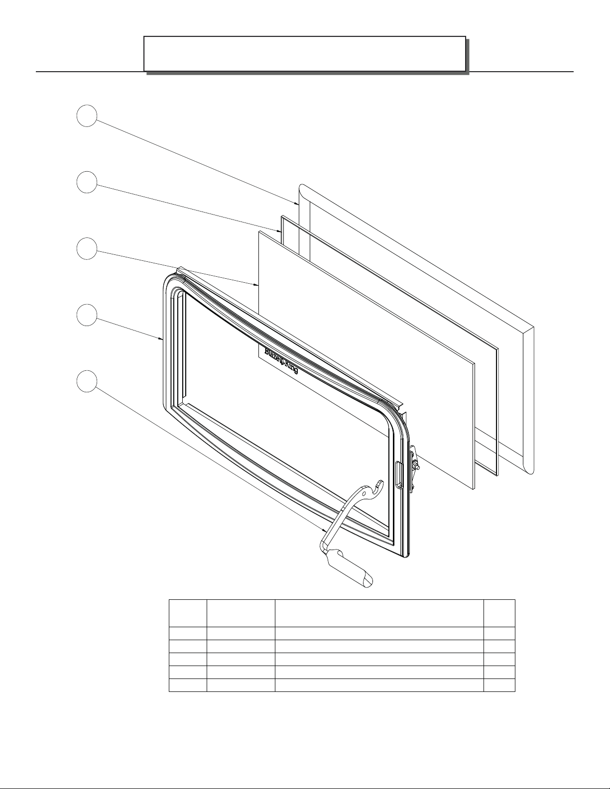
Page 46
REPLACEMENT PARTS
AF25
=$)&$67'225
,7(0
12
180-AF25 v1.07 October 2, 2018
3$57
180%(5
$)&$67'225
$6
*/$66&(5$0,&00L
*$6.(7;:36$63(&)7
*$6.(751'%/.0,')7
'(6&5,37,21
6&'225+$1'/(
47<
Page 47
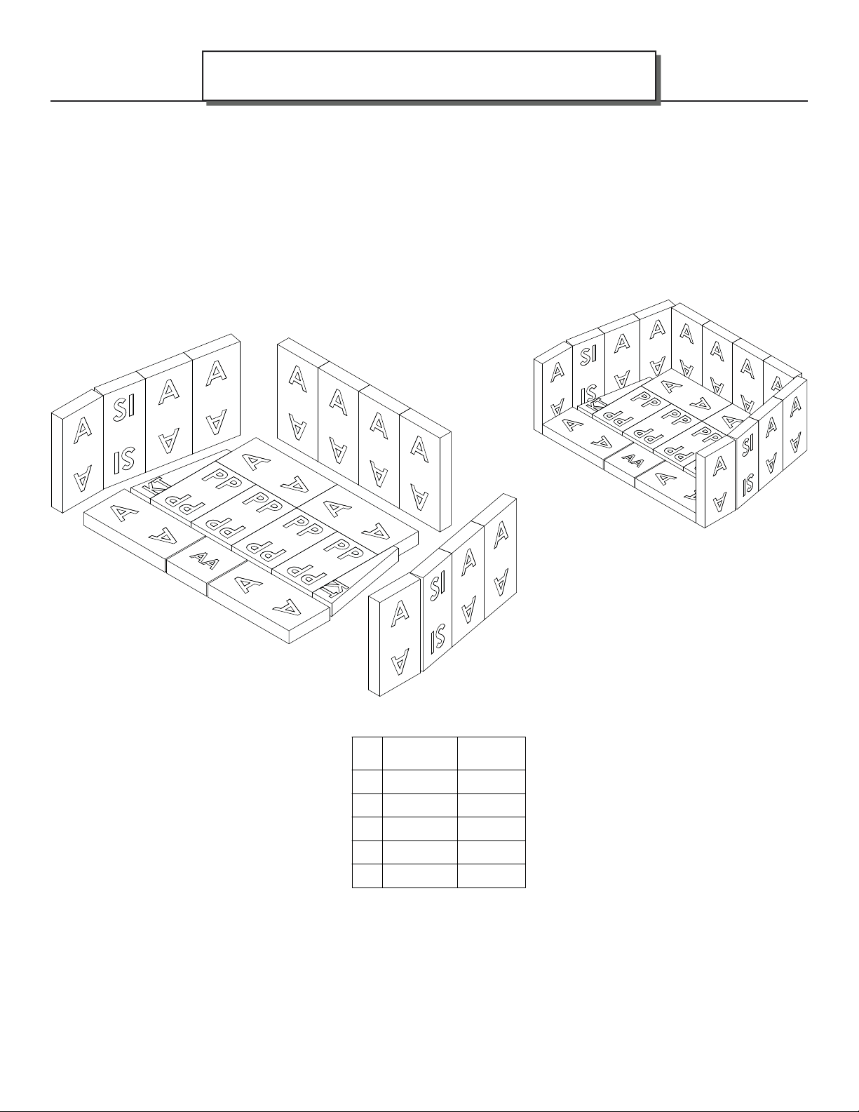
AF25
REPLACEMENT PARTS
Refractory Brick Layout
Page 47
,7(0
12
3$57
180%(5
$6L]H%ULFN
$$6L]H%ULFN
.76L]H%ULFN
336L]H%ULFN
6,6L]H%ULFN
47<
180-AF25 v1.07 October 2, 2018
Page 48
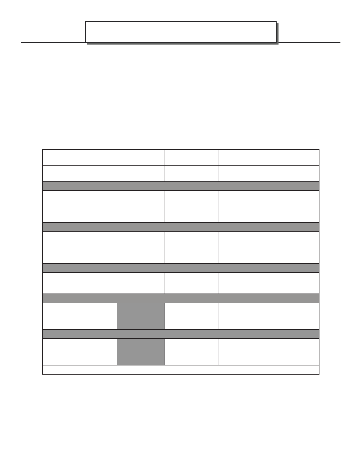
Page 48
WARRANTY
BLAZE KING WOOD LIMITED WARRANTY
Blaze King and Valley Comfort’s respective brands extend the following warranty for wood fi red
appliances purchased from an authorized Blaze King / Valley Comfort dealer and installed in
the United States of America or Canada. Warranty starts with date of purchase by the original
owner (End User) except as noted for replacement parts.
AF25
Warranty Period
Parts Labor Wood
1 Year X
2 Years X
5 Years 2 Years X
6 Years X
Components
Covered
All parts, materials and surface
fi nishes (fl aking and peeling) Subject
to Conditions, Exclusion, and
Limitations listed.
Fan assemblies and motors, thermal
sensors, catalytic thermometer, bi-
metallic thermostat assembly, door
handle metal components.
Firebox & Heat Exchanger, Bypass
Door Steel Components
Catalyst Combustor ( see
Conditions, Exclusions, and
Limitations)
1 Year X Other Replacement Parts
See Conditions, Exclusions, and Limitations
180-AF25 v1.07 October 2, 2018
Page 49

AF25
Blaze King Wood Limited 5 Year Warranty
Blaze King is the manufacturer of the Blaze King line of heating products. At Blaze King, our commitment to the highest
level of quality and customer service is the most important thing we do. Each Blaze King appliance is built on a tradition of
using only the fi nest materials and is backed by our limited warranty to the original purchaser. With Blaze King, you’re not
just buying a appliance; you’re buying a company with years of unequalled performance and quality.
Limited Six (6) Year Warranty:
The CATALYTIC COMBUSTOR is under warranty by Blaze King for six (6) years from the date of original retail purchase.
The purchaser shall pay the following share of the then current retail price for the combustor: The fi rst three (3) years
no charge, 4th year 60%; 5th year 70%, 6th year 80%. The Combustor must be returned to your dealer along with a
completed COMBUSTOR FAILURE REPORT and original proof of purchase document.
Limited (5) Year Warranty:
Under this warranty, Blaze King covers the appliance body and accessories against defects in materials and
workmanship, for part repair or replacement for the fi rst fi ve (5) years *** to the original purchaser. This Warranty covers:
All Steel fi rebox components against defects in material and workmanship. Please see the exclusions and limitation
section below as certain restrictions and exclusions apply this warranty.
Limited Two (2) Year Warranty:
Under this warranty, Blaze King covers, fan assemblies , modular thermostat and door handle steel components against
defects in materials and workmanship, for part repair or replacement and limited labor for the fi rst two (2) years to the
original purchaser. Please see the exclusions and limitation section below as certain restrictions and exclusions apply to
this warranty.
WARRANTY
Page 49
Limited One (1) Year Warranty:
Under this warranty, Blaze King covers all parts and materials against defects in materials and workmanship including
exterior paint fi nishes, for part repair or replacement and limited labor for the fi rst year to the original purchaser. Please
see the exclusions and limitation section below as certain restrictions and exclusions apply to this warranty.
How the Warranty Works
1. All warranties by the manufacturer are set herein and no claim shall be made against the manufacturer on any oral
warranty or representation. All claims under this Limited Warranty must be made in writing by your dealer.
2. Any appliance or part thereof that is repaired or replaced during the Limited Warranty period will be warranted under
the terms of the Limited Warranty for a period not exceeding the remaining term of the original Limited Warranty or six
(6) months, whichever is longer.
3. For any part or parts of this appliance, which in our judgment show evidence of defects, Blaze King reserves the
option to repair or to replace the defective part(s) through an accredited distributor or agent, provided the defective
part is returned to the distributor or agent, transportation prepaid, if requested.
4. If you discover a problem that you think may be covered by the Limited Warranty, you MUST REPORT it to your Blaze
King dealer WITHIN 30 DAYS from the date the problem was fi rst detected, giving them proof of purchase and the
date of purchase. The dealer will investigate the problem and work with Blaze King to determine whether the problem:
a) Is covered by the Limited Warranty or
b) Can be fi xed in your home or does the product need to be returned to Blaze King for repair.
5. If Blaze King determines that the appliance needs to be returned to Blaze King for repair, the customer has the
responsibility and the expense of removing it from their home and shipping it to Blaze King. If the problem is covered
by the Warranty, Blaze King will repair or replace the item at their discretion and the customer will be responsible for
return shipping and re-installation in their home.
6. If the problem is not covered by the Limited Warranty, the customer will be responsible for all repair costs, as well as
all storage, shipping and the cost of removing and re-installing the appliance.
If you are not satisfi ed with the service provided by the Blaze King dealer, write to Blaze King at the address listed on
the last page of the Owner’s Manual. Include a copy of the original purchase invoice and a description of the problem.
180-AF25 v1.07 October 2, 2018
Page 50

Page 50
Exclusions and Limitations:
WARRANTY
AF25
1. This Warranty does not cover tarnish, discoloration or wear on the plated surfaces Painted fi nishes will change color
after initial fi ring and will continue to change through the lifetime of the appliance. This is normal occurrence for all
high temperature coatings.
2. This Warranty does not cover gasket material or fi rebrick.
3. Blaze King strongly recommends installation by a certifi ed installer. Failure to comply may adversely aff ect coverage
under the terms of this warranty. This Limited Warranty covers defects in materials and workmanship only if the
product has been installed in accordance with local building and fi re codes; in their absence refer to the owner’s
manual. If the product is damaged or broken as a result of any alteration, wilful abuse, mishandling, accident, neglect,
or misuse of the product, the Limited Warranty does not apply.
4. The appliance must be operated and maintained at all times in accordance with the instructions in the Owner’s
Manual. If the unit shows signs of neglect or misuse, it is not covered under the terms of this Warranty policy.
Performance problems due to operator error will not be covered by the Limited Warranty policy.
Some minor expansion, contraction, or movement of certain parts and resulting noise, is normal and not a defect and,
therefore, is not covered under this Limited Warranty.
5. Misuse includes over-fi ring. Over-fi ring can be identifi ed later by warped plates and paint pigment being burnt off .
Over-fi ring this appliance can cause serious damage and will nullify the Limited Warranty.
6. The Limited Warranty will cover glass thermal breakage only and will not cover misuse of the appliance glass,
including but not limited to:
a) Glass that is struck, has surface contaminates or has had harsh or abrasive cleaners used on it.
b) If the door is slammed or is closed while wood in the fi rebox is protruding out the appliance opening thus striking
the glass.
7. This warranty does not cover products made or provided by other manufacturers and used in conjunction with the
operation of this appliance without prior authorization from Blaze King The use of such products may nullify the
Limited Warranty on this appliance. If unsure as to the extent of this Limited Warranty, contact your authorized Blaze
King dealer before installation.
8. Blaze King will not be responsible for inadequate performance caused by environmental conditions.
9. The Limited Warranty does not cover installation and operational related problems such as use of downdrafts or
spillage caused by environmental conditions. Environmental conditions include but are not limited to nearby trees,
buildings, roof tops, wind, hills, mountains, inadequate venting or ventilation, excessive off sets, negative air pressures
or other infl uences caused by mechanical systems such as furnaces, fans, clothes dryers etc.
10. The Limited Warranty does not cover damage caused by burning salt-saturated wood, corrosive driftwood, chemically
treated wood or any fuel not recommended in the Owner’s Manual (use cord wood only).
11. The Limited Warranty is void if:
a) The appliance has been operated in atmospheres contaminated by chlorine, fl uorine or other damaging chemicals.
b) The appliance is subject to submersion in water or prolonged periods of dampness or condensation.
c) Any damage to the unit, combustion chamber or other components due to water, or weather damage which is the
result of, but not limited to, improper chimney/venting installation.
d) Salt air in coastal areas or high humidity can be corrosive to the fi nish; these environmental conditions can cause
rusting. Damage caused by salt air or high humidity is not covered by the Limited Warranty.
12. Exclusions to the Limited Warranty include: injury, loss of use, damage, failure to function due to accident, negligence,
misuse, improper installation, alteration or adjustment of the manufacturer’s settings of components, lack of proper
and regular maintenance, alteration, or act of God.
13. The Limited Warranty does not cover damage caused to the appliance while in transit. If this occurs, do not operate
the appliance and contact your courier and/or dealer.
14. The Limited Warranty does not extend to or include paint, door or glass gaskets or fi rebricks damage caused by
normal wear and tear, such as paint discoloration or chipping, worn or torn gaskets, chipped or cracked fi rebrick, etc.
15. The Limited Warranty does not include damage to the unit caused by abuse, improper installation, or modifi cation of
the unit.
16. Damage to plated surfaces caused by fi ngerprints, scratches, melted items, or other external scores and residues left
on the plated surfaces from the use of abrasive cleaners or polishes is not covered in this warranty.
17. Blaze King is free of liability for any damages caused by the appliance, as well as inconvenience expenses and
materials. The Limited Warranty does not cover incidental or consequential damages.
180-AF25 v1.07 October 2, 2018
Page 51

AF25
WARRANTY
Page 51
18. The Limited Warranty does not cover any loss or damage incurred by the use or removal of any component or
apparatus to or from the Blaze King appliance without the express written permission of Blaze King and bearing a
Blaze King label of approval.
19. Any statement or representation of Blaze King Products and their performance contained in Blaze King advertising,
packaging literature, or printed material is not part of the Limited Warranty.
20. The Limited Warranty is automatically voided if the appliance’s serial number has been removed or altered in any way.
If the appliance is used for commercial purposes, it is excluded from the Limited Warranty.
21. No dealer, distributor, or similar person has the authority to represent or warrant Blaze King Products beyond the
terms contained within the Limited Warranty. Blaze King assumes no liability for such warranties or representations.
22. Blaze King will not cover the cost of the removal or re-installation of the appliance, hearth, facing, mantels, venting or
other components.
23. Labor to replace or repair items under this Limited Warranty will be covered per our warranty service fee
reimbursement and labor rates are set per component schedule. Labor rates vary from location to location and as
such total labor costs may not be covered. Please consult with your dealer or service technician for any additional
charges such as travel time or additional labor charges that may apply.
24. For parts of the Blaze King wood appliance or fi replace insert warranted beyond the fi rst year, the fi ve year limited
warranty will have the same obligations as described in this document, provided, however that the purchaser shall
pay the following percentage of the then current retail cost of the repair or the replacement, according to the year after
purchase in the which the defect is brought to the attention of Blaze King.*** During the 2nd year----purchaser pays
20%. 3rd year ----purchaser pays 40%. 4th year -----purchaser pays 60%. 5th year---- purchaser pays 80%.
25. If a defect or problem is determined by Blaze King to be non warrantable, Blaze King is not liable for travel costs for
service work. In the event of in-home repair work, the customer will pay any in-home travel fees or service charges
required by the Authorized Dealer.
26. At no time will Blaze King be liable for any consequential damages which exceed the purchase price of the unit.
Blaze King has no obligation to enhance or modify any appliance once manufactured (example: as a appliance model
evolves, fi eld modifi cations or upgrades will not be performed).
27. This Limited Warranty is applicable only to the original purchaser and it is nontransferable.
28. This warranty only covers Blaze King Products that are purchased through an authorized Blaze King dealer.
29. If for any reason any section of the Limited Warranty is declared invalid, the balance of the warranty remains in eff ect
and all other clauses shall remain in eff ect.
30. The Limited Warranty is the only warranty supplied by Blaze King, the manufacturer of the appliance. All other
warranties, whether express or implied, are hereby expressly disclaimed and the purchaser’s recourse is expressly
limited to the Limited Warranty.
31. Blaze King and its employees or representatives will not assume any liability for damages, either directly or indirectly,
caused by improper usage, operation, installation, servicing or maintenance of this appliance.
32. Blaze King reserves the right to make changes without notice. Please complete and mail the warranty registration
card and have the installer fi ll in the installation data sheet in the back of the manual for warranty and future reference.
33. Blaze King is responsible for stocking parts for a maximum of seven (7) years after discontinuing the manufacture
or incorporation of the item into its products. An exception to this would be if an OEM supplier is not able to supply a
part.
34. “Installation into unfi nished or uninsulated basements often forces the user to operate the appliance continuously at
peak output or over-fi re in an eff ort to overcome heat loss. Blaze King does not recommend such installations. Doing
so may adversely aff ect the appliance and therefore coverage under the terms of this limited warranty.”
180-AF25 v1.07 October 2, 2018
Page 52
Page 52
INSTALLER NOTES
AF25
Installer: Please complete the following information
Dealer Name & Address:________________________________________________________
____________________________________________________________________________
Installer (print): _______________________________________________________________
Installer (sign): _______________________________________________________________
Phone #: ____________________________________________________________________
Date Installed:________________________________________________________________
Serial No.: ___________________________________________________________________
180-AF25 v1.07 October 2, 2018
 Loading...