

Page 1
p:__ :
,q,_ ,:, ..: :
^r. i
..
:’ _.
:
..‘:.
‘I
‘.:‘%‘: ,,.,.,
:’
vat&
@;a~@i~os
con
conmutables
limi&ibn
Bosch Group
High-pass
de
Page 2

TABLE OF CONTENTSTABLE OF CONTENTS PAGEPAGE
Introduction 3
Owner's Record 3
Key features 3
Understanding your amplifier 4
Connections 5
Controls and their use 6
System design guide 7-8
Installation and safety precautions 9
Final installation 10-11
Trouble-shooting guide 12
Specifications 13
Limited warranty 14
TABLE DES MATIÈRES PAGE
Introduction 15
Archive du propriétaire 15
Caractéristiques-clé 15
Comprendre le fonctionnement de l'amplificateurer 16
Raccordements 17
Commandes et leur utilisation 18
Guide de conception du système 19-20
Installation and safety precautions 21
Montage final 22-23
Guide de dépannage 24
Spécifications 25
Garantie limitée 26
INDICE DE MATERIAS PAGE
Introduccion 27
Notas del propietario 27
Caracteristicas clave 27
Funcionamento de su amplificador 28
Conexiones 29
Controles y manera de usarlos 30
Guia de diseño del sistema 31-32
Precauciones de instalacion y seguridad 33
Installacion final 34-35
Guía para solucionar problemas 36
Especificaciones 37
Garantia limitada 38
22
Page 3

INTRODUCTION INTRODUCTION
Congratulations on your purchase of the world's finest brand of car audio amplifiers. We have invested
tremendous effort in the design process of the new VELOCITY
superior musical performance. Leading edge technologies such as Distortion Limiting and high Signalto-Noise Voltage Controlled Amplifier input stages, previously found only in the professional audio sound
reproduction and enhancement market, have been implemented into your VELOCITY
For maximum performance and reliability we highly recommend that your new VELOCITY
amplifier be installed by an authorized Blaupunkt dealer. We also recommend Blaupunkt cd or cassette
units, speaker systems, and accessories to expand the listening experience which might be limited by
lesser quality components.
Finally, we remind you to practice safe listening habits using common sense. Continuous exposure to
listening levels over 100 decibels may cause permanent hearing loss. Many high power, multi-speaker
systems today are capable of Sound Pressure Levels exceeding 130 dB.
TM
series amplifiers in order to achieve
TM
amplifier.
TM
series
OWNER'S RECORD
The model and warranty numbers are located on the bottom of the unit. Please record these numbers in
the space provided below. Refer to these numbers whenever you call upon your Blaupunkt dealer.
MODEL: VELOCITYTM V420
WARRANTY NUMBER:
PURCHASE DATE:
DEALER:
INSTALLER:
OTHER INFORMATION:
KEY FEATURES
# Distortion Limiting (THDL) is entirely new to the car audio aftermarket and is used to reduce the
annoying acoustical pops and cracks present during high signal levels. It is acoustically transparent
until high signal levels drive the amplifier into distortion.
# 2 ohm stability allows for paralleling of multiple speakers for increased power output and/or
additional speakers for additional sound pressure levels due to increased cone area.
# Switchable 100 Hz high-pass filters limit the lower bass signals from entering small 3.5 or 4 inch
speakers thus better distributing the low frequency power to additional power amps for dedicated low
frequency speakers.
# Wide range input gain controls (0.3 - 6.0 V rms) allow for a variety of radio interface voltages, even
directly from the high level outputs of many factory radios.
# Independent front/rear gain controls allow for separate loudness level settings of the front and rear
speakers in the vehicle without adjusting the fader control in the radio.
# High impedance differential inputs sense noise riding on the RCA input cable center conductor and
shields and effectively subtracts the noise out of the input stage.
33
Page 4
UNDERSTANDING YOUR AMPLIFIER
...WHAT IS AN AMPLIFIER?...
An amplifier, by definition, is a device that receives a small audio signal on its input and reproduces it
with larger voltages (or current) on its output. Ideally there should be no internal modifications of the
signal other than voltage or current level. If there are any changes in the signal character it is considered
a "distortion" of the input signal.
A perfect amplifier will be able to reproduce any output voltage regardless of input signal level, but this is
impossible due to upper limits created by the voltages found in a car, typically 12 - 15 volts DC. The
amplifier's output stage cannot swing voltages that exceed the upper limit commonly referred to as the
voltage "rails", as in locomotive train tracks. If the input signal is driven to high levels, the outputs try to
follow this path but crash into the "rails" thus turning musical sine waves into very unmusical square
waves. Here is where your new Blaupunkt VELOCITY
The Blaupunkt VELOCITYTM series of amplifiers have a very unique feature called Distortion Limiting
(THDL) which tolerates high input voltage levels but prevents ugly sounding distortion products common
to nearly all other amplifiers. An input voltage sensing network looks at the incoming signal and adjusts
the feed-through gain of the amplifier so quickly that high level bass notes cannot drive the amp into
distortion yet lower signal level mid and high frequencies pass through without gain modification. This is
done within milliseconds, so "gain pumping" acoustical byproducts of inexpensive audio limiters are
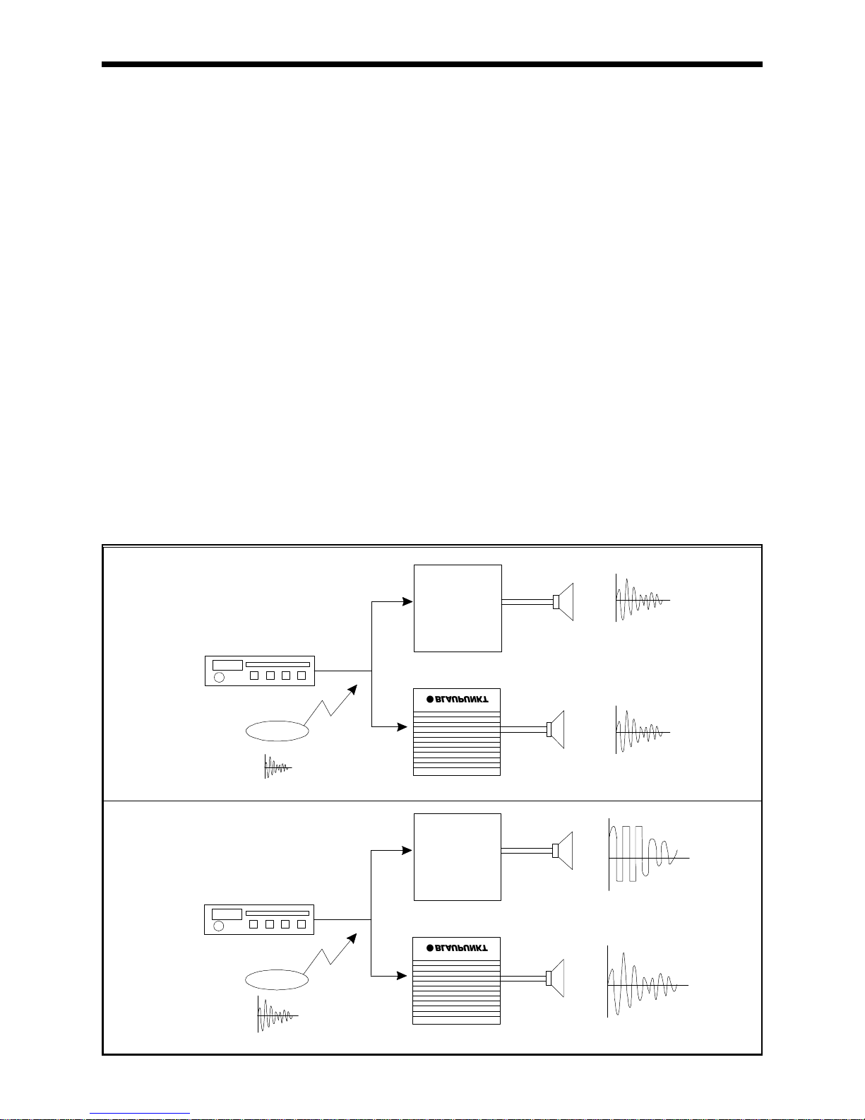
never encountered. Below is a visual description of a high level audio signal passing through a typical
car audio amplifier and then through the new Blaupunkt VELOCITY
TM
amplifier is uniquely impressive.
TM
amplifiers.
"DISTORTION LIMITING SIGNAL CHARACTERISTICS"
Low Volume
Typical Amplifier
0.1 Vrms
Blaupunkt with THDL
High Volume
1.0 V
rms
44
(Clipping)
Typical Amplifier
Blaupunkt with THDL
Page 5
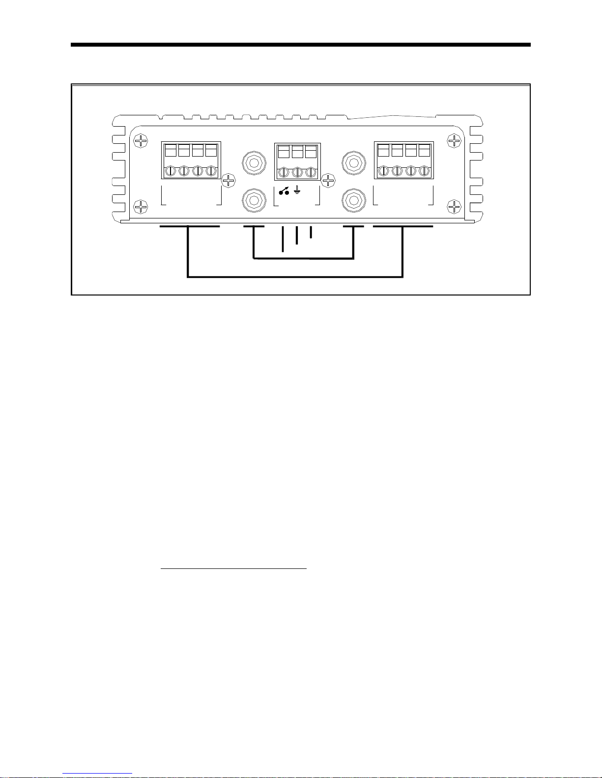
CONNECTIONS
"CONNECTION SIDE OF AMPLIFIER"
INPUTSINPUTS
+ - + -
+ - + -
LR RR
OUTPUTS
OUTPUTS
+12V
POWER
2
1
RFRR
LFLR
3
4
+ - + -
+ - + -
LF RF
OUTPUTS
OUTPUTS
5
1. TRIGGER LINE - This connection is the connection point that allows the amplifier to be switched on
from a remote location (usually the radio). When a positive voltage is applied to this terminal the
amplifier will switch on. This connection is normally made from the power antenna lead of the radio
or a dedicated trigger line. It will turn the amp on for any voltage above 10 volts. Make sure the
radio's power antenna lead is activated only when the radio is turned on.
2. GROUND LINE - This is the high current ground connection to the chassis of the car. It should be
connected to a clean ground connection in the car, capable of handling high current loads. Do not
run a wire up to the car battery ground for this line.
3. BATTERY LINE - A high current, fused line should be connected at this point with battery level
voltages (typical 12.5 - 14.5 V DC) available 24 hours a day.
4. LEFT/ RIGHT RCA LINE INPUTS - These lines connect to the RCA output jack of a radio, or
directly from the high level audio outputs from a radio. These connectors are Gold plated for
superior audio transmission and to prevent
corrosion over time.
5. SPEAKER OUTPUTS - These connections are used to connect loudspeakers with 2 ohm or higher
speaker impedance. It is imperative that these lines NOT be connected or touch the chassis of the
car in any way. Also, the (-) lead of the left channel is not electrically connected to the (-) lead of the
right channel so common grounds cannot be used. Speaker wire gauges of up to 12 gauge in size
can be accommodated by these terminals.
55
Page 6

CONTROLS AND THEIR USE
"CONTROL SIDE OF AMPLIFIER"
1.0 1.0
100 Hz
HIGH-PASS
6.0 6.00.3 0.3
FRONT REAR
GAIN (V)
1 2 3
5-30,000 Hz BYPASS
THD
1. INPUT GAIN CONTROL - This control matches the radio or preamp output voltage to the amplifier's
input voltage so that full output can be achieved. Most radios provide only 0.5-1.0V rms output, so
this control will easily accept nearly any input voltage. Turning the control clockwise effectively
makes the amp play louder.
2. FREQUENCY LIMIT SETTING - In the full-range mode (5-30,000 Hz) the amp reproduces all
frequencies heard by humans. With the switch in the High-pass mode, only information above 100
Hz is sent to the speakers thus allowing for an additional subwoofer amplifier to properly reproduce
the bass frequencies.
3. DISTORTION LIMITING ON/OFF - When turned on, this control enables the THDL circuit. When
switched on (to the left) the circuit greatly reduces all distortion products at high levels but is
electrically transparent at all other listening levels. In the BYPASS mode, the distortion limiting
feature is disabled so unwanted clipping harmonics can pass on to the speakers.
66
Page 7

SYSTEM DESIGN GUIDE
It is unfortunate that most people don't realize how loud 20 watts of audio actually is. They often
discount this power class without taking into account its cost effective solution at reasonable
performance. When used with competent full-range speakers, or in conjunction with a dedicated
subwoofer amp and speakers, the combination can be astounding! Therefore, one of the most difficult
decisions in amplifier usage is an optimized power amplifier configuration. The Blaupunkt VELOCITY
series of amplifiers has the versatility to offer multiple installations but two particular designs are the
most common in this class.
First is the "Basic 4 channel" design. A number of head units today offer low level RCA outputs, usually
all four audio channels. These RCA lines are connected to the input stage of the amplifier with the four
output speaker lines connected to four good quality full-range speakers. With 6x9" high performance
loudspeakers in the trunk of a sedan, the acoustical results can be impressive. The real benefit is the
minimum installation complexity for generally high performance.
"BASIC 4 CHANNEL AMPLIFIER CONFIGURATION"
TM
100Hz
HIGH-PASS
5-30,000 Hz
LF
20 Watts
LR
20 Watts
+
+
-
Blaupunkt V420
+
20 Watts
+
20 Watts
-
RF
RR
77
Page 8

The second most common configuration is that of a "Bi-amplified" speaker system. By breaking the
audio spectrum (20 - 20,000 Hz) into two parts (e.g., above and below 100 Hz) amplifier power can be
better proportioned to the needs of most music. But, you don't want the two parts of the spectrum to
overlap since each requires different amplifier power values and speaker designs.
Bass information usually requires a lot more power than mid and high frequencies for proper
reproduction. For truly dynamic performance, a dedicated subwoofer amplifier and speaker are needed
for the low frequencies. A "Bi-amplified" system allows for a lower powered mid and high frequency
amplifier but a much higher powered unit for the bass region since larger signal levels are found here in
most music. The musical results can be astounding!
"BI-AMPLIFIED SPEAKER CONFIGURATION"
100 Hz
HIGH-PASS
5-30,000Hz
LF
20 Watts
LR
20 Watts
Subwoofer Amplifier
+
+
-
Blaupunkt V420
+
20 Watts
+
20 Watts
-
RF
RR
88
Page 9

INSTALLATION AND SAFETY PRECAUTIONS
!! WARNING !!
; ALWAYS DISCONNECT THE (+) LEAD FROM THE BATTERY OF THE
VEHICLE BEFORE DOING ANY INSTALLATION WORK!
; DO NOT INSTALL THIS UNIT IN THE ENGINE COMPARTMENT!
; DO NOT RUN WIRES UNDERNEATH OR OUTSIDE THE VEHICLE!
!! SAFETY PRECAUTIONS !!
1. Analyze the mounting location carefully to avoid damaging gas tanks, electrical wires, and/or
hydraulic lines.
2. Every effort should be made to provide adequate ventilation, protection from engine heat, direct
sunlight, rain, and dirt.
3. This unit is designed for use only with 12 volt DC negative ground vehicle systems.
4. This unit is NOT designed for use with common ground speakers. All speakers MUST be
connected to both positive and negative terminals.
5. Fuse the +12V lead of the amplifier before making any electrical connections in the vehicle.
Fuse
the line as close to the battery as possible. Always use the fuse supplied with this amp
and never
increase the fuse size (for example, 10A) in case it does blow.
6. Be sure all power grounds are clean. Scrape off paint if necessary to guarantee this.
7. Make wiring connections from one component to the next, making sure that you plug radio or
equalizer outputs to amplifier inputs and not outputs to outputs.
8. Do not run power cables and audio (RCA) cables together. You can minimize noise radiation by
running the power cables on one side of the car and the signal cables on the opposite side.
9. Avoid sharp edges and door jambs when running the wires. Electrical tape or grommets should
be used protect the wires when they are routed through holes.
10. Make sure all wire connections are secure and protected so there is no danger of nicks or
pinched
electrical lines.
11. FOR SAFE DRIVING keep the listening levels low enough not to mask outside noises.
12. Avoid playing your car audio system for long periods of time at high listening levels when the
engine
is not running. This will prevent unnecessary battery drain.
99
Page 10

FINAL INSTALLATION
Proper installation of your amplifier requires several items; adequate mounting and ventilation, "clean"
power and ground connections, proper input interface, and proper output interface.
ADEQUATE MOUNTING AND VENTILATION
Inevitably this size of amplifier will be mounted under the dashboard due to convenience. Although
acceptable, this location does not offer ventilation to the amplifier that a better location under the front
seat might have. If possible though, try mounting the amplifier on a vertical surface with the fins
up/down for best vertical air movement. The mounting screws supplied with this unit should be used for
the most secure installation.
"CLEAN" POWER AND GROUND
Nearly every vehicle built in the last 10 years has more than enough current capability to provide
adequate power for your Blaupunkt amplifier. This unit will operate over a range of 10-18 volts DC. The
wire and fuse provided should be used to ensure good electrical connection and long term reliability. If
you choose to use an alternative wire, the connections can accept up to 12 gauge (AWG) wire. The fuse
should be installed in-line with the amplifier before the line is attached at the "+12V" terminal on the
amplifier.
0.5" 0.5"
(13 mm) (13 mm)
Fuse
POWER
+12V
INPUTSINPUTS
RFRR
LFLR
+ - + -
+ - + -
LF RFLR RR
OUTPUTS
OUTPUTS
Ground
Although usually not critical in lower power amplifiers (20 watts/channel), proper ground connections
should be made. The black wire to the ground terminal of the amplifier should be terminated at the other
end to a clean metal surface under the dashboard. If alternator whine is picked up then a "star"
grounding scheme (shown below) should be used to ensure a common ground point for all stereo
components.
Radio
Equalizer (Optional)
+12V +12V +12V
1010
Blaupunkt V420
"Star" Ground
Page 11

PROPER INPUT INTERFACE
This amplifier can tolerate input signals up to nearly 6 V rms over the RCA input jacks. Even though
differential inputs are used, noise can still enter the shields of the RCA cables if they are run near noise
producing objects.
Due to high input signal capabilities, people will more than likely want to interface the high level output of
a radio to the input of the amplifier. This can be easily done by connecting the "+" lines of the four
speaker outputs to the center conductors of the RCA jacks. One signal ground reference wire is then
connected from the radio chassis to the four shields of the RCA lines connecting to the amplifier input.
INPUTSINPUTS
RFRR
+ - + -
+ - + -
LR RR
OUTPUTS
OUTPUTS
POWER
+12V
LFLR
+ - + -
+ - + -
LF RF
OUTPUTS
OUTPUTS
Blaupunkt V420
PROPER OUTPUT INTERFACE
Your new amplifier can be mated to loudspeaker loads as low a 2 ohms. Care should be taken to verify
the loudspeaker's power handling capability to prevent damage to the unit should it's rating fall under the
output power of this amp.
Additional care should be taken to ensure proper loudspeaker polarity to prevent out-of-phase signals at
full range speakers. This will severely reduce the bass output if two 6x9 inch speakers are out-of-phase,
for example.
INPUTSINPUTS
RFRR
+ - + -
+ - + -
LR RR
OUTPUTS
OUTPUTS
POWER
+12V
LFLR
+ - + -
+ - + -
LF RF
OUTPUTS
OUTPUTS
Blaupunkt V420
1111
Page 12

TROUBLE-SHOOTING GUIDE
SYMPTOM PROBABLE CAUSE & SOLUTIONS
1. No power (blue remote turn-on light
is off)
2. Power but no sound (blue remote
turn-on light is on)
! Check connections to the amplifier's +12 volt, Ground, and remote lines. Verify
the appropriate voltages are at their terminals (11-15 VDC).
! Check the main power connection at the battery.
! Check fuse in power line. If fuse is blown, replace it. If it continues to blow, see
your Blaupunkt dealer.
! Disconnect all speakers and try to power up unit. If it now turns on, a speaker
short is probable.
! Check all RCA input cables and speaker output cables.
! Test the speaker with a VOM to verify >2 ohm loads per channel.
3. No sound from one channel
or entire side
4. Very low sound level ! Check radio balance and fader control positions.
5. Power amplifier turns on and off
repeatedly (Motor boating)
6. Amp sounds fine but gets
very warm to the touch
7. Amplifier turns off during
loud passages or is distorted
8. Amplifier turn-on/off pops or noises ! Disconnect the RCA input lines to the amp and turn amplifier unit on and off via
9. Crackling noise on AM and FM
radio, but not on tape or cd. Varies
with accelerator but is present at all
times.
(This is "radiated" noise)
10. Whining noise (alternator whine)
occurs while engine is running and
varies in pitch with engine speed
{this noise VARIES with radio's
volume setting}.
11. Whining noise (alternator whine)
occurs while engine is running and
varies in pitch with engine speed
{this noise DOES NOT vary with
radio's volume setting}.
! Check radio balance and fader control positions.
! Check loudspeaker connections.
! Check cd changer connections (if applicable).
! Check amplifier's input gain control setting - adjust for higher output levels if
possible.
! Head unit may have extremely low output voltage. A step-up voltage "line driver"
may have to used.
! Make sure connections at battery are tight.
! Check battery voltage at amp using VOM; it should be 11-15 VDC.
! Check all radio and amplifier ground connections.
! Input gain control is set too high; lower input level accordingly.
! Verify that speaker load impedances are > 2 ohms per channel.
! Verify that the mounting location allows for free air movement around the amp.
The largest area should be above the unit since heat rises.
! Input stage being severely overdriven. Lower input gain.
! Verify that speaker load impedances are > 2 ohms per channel.
! Verify that one of the speaker outputs is not shorted to the chassis of the car.
the Trigger line. If pop goes away, the amp is turning on faster than the time
required for the radio outputs to settle down. A turn on delay line may be needed.
! If the noise persists, disconnect the Trigger line from the head unit and try
connecting directly to the battery. If the noise goes away, use a relay to switch
the trigger line from the clean power source.
! Make certain the problem is "radiated" noise by placing a portable FM radio near
the car engine. If noise is picked up, then it is an automotive problem and not
your system.
! Make sure the spark plugs and wires are <2 years old; otherwise replace.
! Verify that the engine block is grounded to the car chassis, not paint.
! Verify the hood is ground to chassis. If not, purchase a flexible metal strap,
scrape off paint at the connections, and screw into place.
! Check power connections to be sure they are clean.
! Reroute power to the radio so that it runs directly from battery bypassing battery
terminal in fuse box.
! Check ground connections to be sure surfaces have been scraped clean for
good connections.
! Check battery ground connection at chassis to make sure it's clean and tight.
Verify that all connections are scraped clean of paint, rust, or grease.
! Check radio and amp connections; you may have to relocate amplifier ground to
same point as radio ground.
! Bypass all equipment between radio and amp (e.g., equalizers, etc.) and connect
directly to amp. If problem goes away, reinsert each component until noise
reappears. Logic shows this part is the problem.
! Check for "high level ground loops"; turn off and disconnect unit grounds, one at
a time, except for the power amp. Turn system back on and check for noise after
each ground is removed.
! Check for RCA shield "signal level ground loops" by disconnecting the shield of
the RCA cable at one end. If noise disappears modify cables accordingly.
1212
Page 13

SPECIFICATIONS
FEATURE/PARAMETER VALUE
GENERAL
Channels 4
Size 1.6 x 5.3 x 6.0 in. (40 x 135 x 150 mm)
Weight 2.5 lbs (1.1 kg)
Crimping screw style speaker terminals YES
Blue LED power YES
Controls on one end/wires other YES
Noise reducing differential inputs YES
Isolated input grounds YES
Subsonic filter YES
Separate front/rear gain controls YES
Remote automotive style fuse YES
Speaker short circuit and to ground protection YES
High, low, reverse voltage protection YES
2 S stable YES
Maximum wire size 12 ga.
PERFORMANCE RELATED
Output stages BTL
Power into 4 S, @ 1 % THD (14.4 V DC) 20 watts
into 2 S, @ 1 % THD 32 watts
THD, @ 1 watt/1 kHz 0.06 %
Signal/Noise @ 1 watt 80 dB
@ full power 93 dB
Frequency response 5 - 30,000 Hz
High-pass crossover frequency 100 Hz, fixed
High-pass crossover slope 12 dB/oct
Input impedance 50 k S
Input voltage range 0.3 - 6.0 V
Current draw @ full power 8 A
@ idle 1.5 A
Efficiency @ full power 65 %
Usable battery voltage 10-18 V
Trigger line voltage 8-18 V
Trigger line current draw 0.05 A
Turn on delay time 1.5 s
Damping factor > 100
Input common mode rejection 55 dB
Power supply ripple rejection 70 dB above 1 kHz
NOTE: Due to ongoing product improvements, specifications and design are subject to change without
advance notice.
1313
Page 14

LIMITED WARRANTY (UNITED STATES)
Robert Bosch Corporation warrants new Blaupunkt audio products and accessories it distributes in the
United States through authorized Blaupunkt dealers, or which are imported as original vehicle equipment
by the automobile manufacturer, to be free from defects in material and workmanship, in accordance
with the following:
For twelve (12) months after delivery to you, the original consumer purchaser, we will repair any
amplifier and replace any accessory which under normal conditions of use and service proves to be
defective in materials or workmanship at no charge to you. However, this warranty does not cover
expenses incurred in the removal or reinstallation of any amp or accessory whether or not proven
defective and does not cover products not purchased from an authorized Blaupunkt dealer.
To obtain performance of this warranty, contact the nearest Blaupunkt authorized repair facility or our
nearest office. A dated purchase receipt or other proof that the product is within the warranty period will
be required in order to honor your claim. Carefully pack the unit and ship prepaid to the servicing
location. For further information, contact your local Blaupunkt retail dealer.
This warranty is limited to the original consumer purchaser and is not transferable. Specifically excluded
from this warranty are failures caused by misuse, neglect, abuse, improper operation or installation,
dropping or damaging the faceplate, or unauthorized service or parts. Also excluded from this warranty
is the correction of improper installation and the elimination of any external electromagnetic interference.
To the extent allowed by law, this warranty sets out your exclusive remedies with respect to products
covered by it, whether for negligence or otherwise. We will not be liable for consequential or incidental
damages, losses, or expenses. THIS WARRANTY IS IN LIEU OF ALL OTHER EXPRESS
WARRANTIES. ANY WARRANTY IMPLIED BY LAW, WHETHER FOR MERCHANTABILITY OR
FITNESS FOR A PARTICULAR PURPOSE OR OTHERWISE, SHALL BE EFFECTIVE ONLY FOR THE
PERIOD THAT THIS EXPRESS WARRANTY IS EFFECTIVE. No attempt to alter, modify, or amend
this warranty shall be effective unless authorized in writing by an officer of Robert Bosch Corporation.
Some states do not allow limitations on how long implied warranties last, or the exclusion or limitation of
incidental or consequential damages, so the above limitations or exclusions may not apply to you. This
warranty gives you specific legal rights and you may also have other rights which vary from state to
state.
NOTICE TO CALIFORNIA OWNERS:
If your Blaupunkt car audio product needs warranty repair service and there is no authorized service
center reasonably close to you, you can return the defective unit to the dealer from whom you purchased
it. Or you can return it to any dealer who sells Blaupunkt products. The dealer may repair or replace the
unit, or, if returned to the dealer from whom purchased, he may partially refund your money, you may
take your Blaupunkt unit to any repair shop and they can repair your unit at our expense unless the repair
cost exceeds the depreciated value of the unit, but you must contact Blaupunkt to receive authorization
to do this before your unit is repaired.
ROBERT BOSCH CORPORATION
BLAUPUNKT DIVISION, UA/CSV
2800 SOUTH 25TH AVENUE
BROADVIEW, ILLINOIS 60153
TEL: 708-865-5200
NOTICE TO NON-U.S.A. OWNERS:
Products sold outside the United States are subject to the limitations of that Blaupunkt region or country.
Please contact your Blaupunkt dealer for further explanation of the repair or replacement process.
1414
Page 15

Bosch Telecom
Robert Bosch Corporation
Sales Group - Blaupunkt Division
2800 South 25th Avenue, Broadview, Illinois 60153
Division Blaupunkt de Robert Bosch Inc.
6811 Century Avenue
Mississauga, Ontario
Canada L5N 1R1
Robert Bosch, SA., DE, C. V.
Dr. Lucio 270
Cols. Doctores, Mexico 06720
Copyright 1993 by the Robert Bosch Corporation
No portion of this work may be reproduced in any form without the written
consent of the Robert Bosch Corporation
The VELOCITY name is trademarked by Rocktron Corporation of
Rochester Hills, Michigan, U.S.A.
Printed in the U.S.A (12/93).
 Loading...