

Page 1
AUTORADIO
Citroen PH 1 - D
7 642 490 394
MC/VKD 3 D93 440 017 BN 07/93
Abgleichanweisung • Alignment Instructions
Instructions d’alignment • Instrucciones de calibrado
D
Weitere Dokumentationen
Ersatzteilliste 3 D93 340 007
Schaltbild 3 D93 240 015
F
Dokumentation complémentaire
Liste de rechanges 3 D93 340 007
Schéma du poste 3 D93 240 015
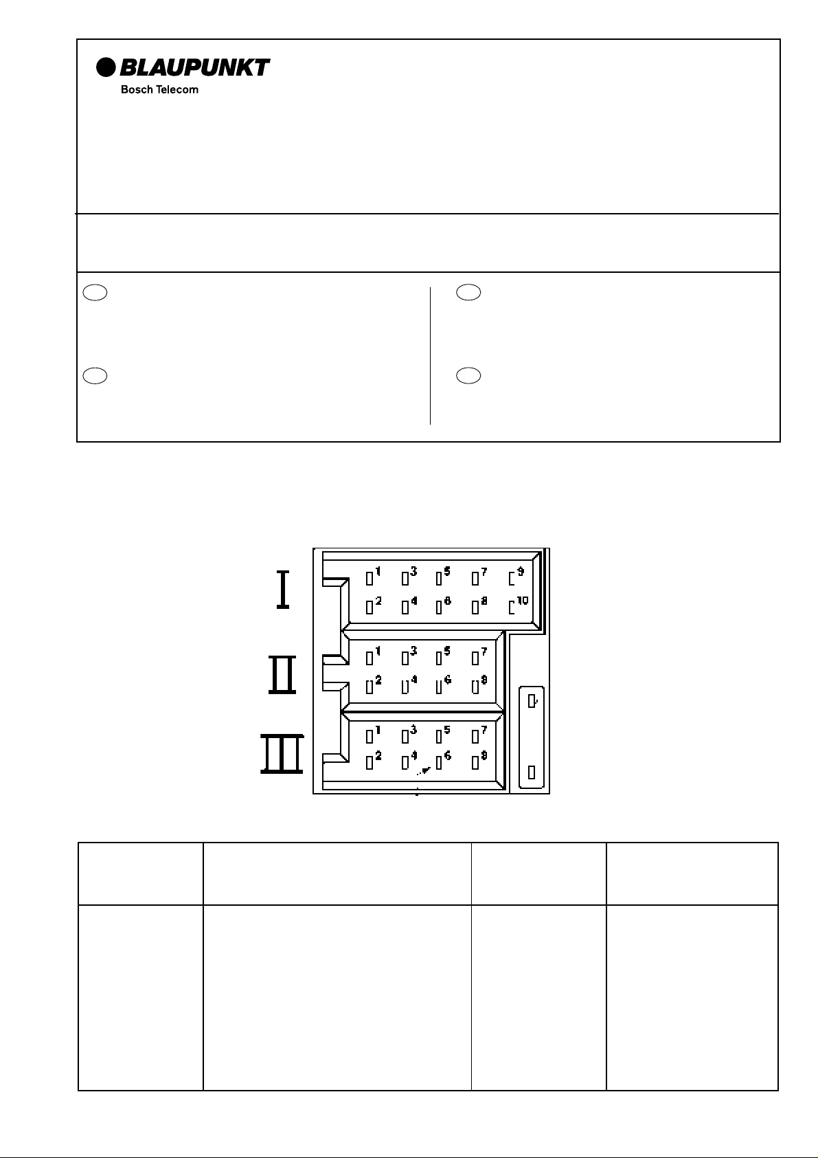
Connector Box
GB
Supplementary documentation:
Spare Part List 3 D93 340 007
Circuit Diagram 3 D93 240 015
E
Documentation suplementaria
Lista de repuestos 3 D93 340 007
Schéma du poste 3 D93 240 015
Connector
1 R (Changer Line - IN) RR + CDC BUS SDA
2 L (Changer Line - IN) RR - CDC BUS SCL
3 Ground (Changer Line - IN) RF + CDC - Ground
4 RC + Uref U5 (Remote control) RF - Permanent (KL 15)
5 RC A2 (Remote control) LF + Automatic antenna
6 RC A1 (Remote control) LF - Illumination
7 RC - illumination (Remote control) LR + Plus (KL 30)
8 RC - Ground (Remote control) LR - Ground
9-
10 -
III III
Page 2
Abgleichbedingungen HF / Alignment conditions RF
D
Während des Abgleichvorgangs muß das Gerät im Testmode
sein.
Der HF - Abgleich muß mit Unterdeckel erfolgen. Nach dem Austausch
von V 800 müssen alle Geräteparameter neu eingestellt werden.
Für den FM-Abgleich sind Abgleichstifte aus Kunststoff oder Keramik
zu empfehlen.
Bevor der elektrische Abgleich durchgeführt wird, müssen verschiedene Vorbereitungen getroffen werden:
1. Fader - Einstellung ......................................Mittelstellung (0)
2. Balance - Einstellung ...................................Mittelstellung (0)
3. Höhen-Einstellung .......................................Mittelstellung (0)
4. Tiefen-Einstellung ........................................Mittelstellung (0)
Im Testmode sind die Stationstasten wie folgt belegt:
Taste 123456
U1 - MHz 87,5 91 95 95 98,2 95
MW - kHz 531 558 1404 1404 1602
LW - kHz 153 198 252 279
GB
The set must be in test mode during the alignment.
The RF - alignment must be done with bottom cover. After exchange
of V 800 all parameters have to be newly adjusted.
For the FM alignment we recommend the use of alignment pins made
of plastics or ceramics.
The following preparatory adjustments have to be carried out prior to
the electrical alignment:
1. Fader adjustment.........................................center position (0)
2. Balance adjustment .....................................center position (0)
3. Treble adjustment ........................................center position (0)
4. Bass adjustment .......................................... center position (0)
In the test mode the allocation of the preset buttons is as follows:
Preset 1 2 3 4 5 6
FM1 - MHz 87,5 91 95 95 98,2 95
MW - kHz 531 558 1404 1404 1602
LW - kHz 153 198 252 279
Testmode / test mode
1. Stationstaste 2 + 5 drücken
2. Gerät einschalten, Stationstasten noch ca. 1 sec. gedrückt halten.
1. Press preset button 2 + 5
2. Switch the unit on and hold the preset buttons depressed for
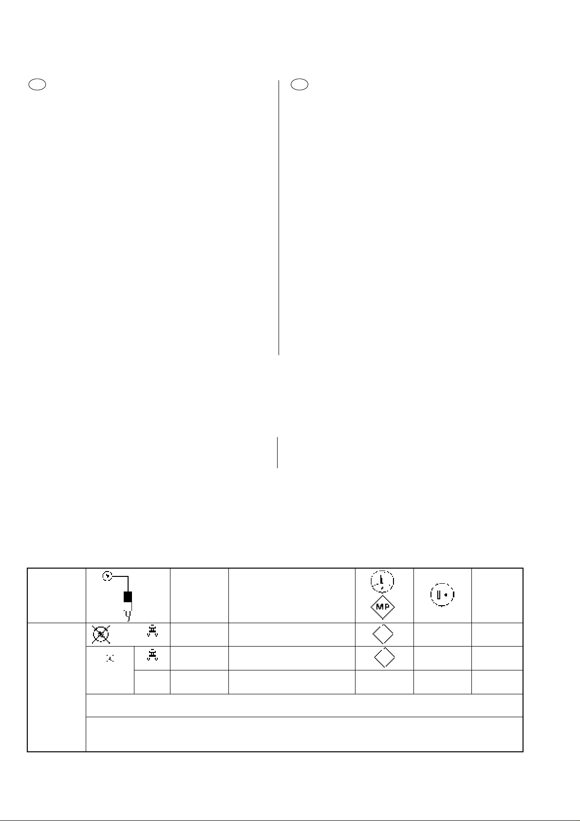
FM
Ri = 60 Ω
Bereich Display Abgleichelement
Range MHz Adjustment element
U
MHz
Ra =
22,5 kHz Hub
deviation
5
98,2 MHz L 6 3,9 V
98,2 MHz L 2 / L 4 max.
5
approx. 1 sec.
∆ U
04
06
Abgleich wiederholen / Repeat the alignment
Der Abgleich ist unterhalb der Begrenzung durchzuführen / The alignment shall be carried out below the limiting value
2
Page 3
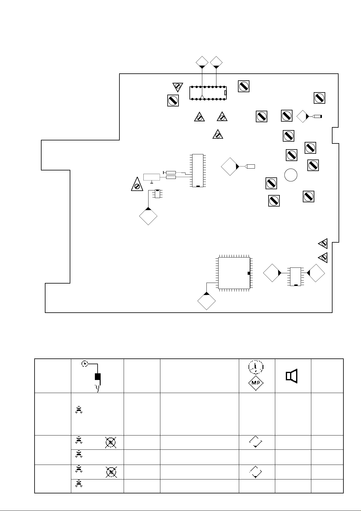
Abgleichdarstellung / Alignment Overall / Reglage de ensemble
Ajuste de conjunto
0608
R 432
DK
ARI
Counter
1
430
R 166
- 10 dB
F 152
V 430
180 K
100 K
R 324
min.
Stereo
23
24
FM
V 152
12 + 13
V 310
3
R 313
19 KHz
Processor
31
R 355
6 dB
7021
V 800
L 6
FM OSZ.
F 1
IF
R 650
L 650
OSZ
558 KHz
L 651
OSZ
153KHz
L 4
98,2 MHz
04
L 602
558 KHz
L 612
153 KHz
AM
L 613
153 KHz
R 1260
450 mV
Dolby
1255 1265
611
V 1250
L 2
98,2 MHz
C 101
L 603
558 KHz
L 660
IF
R 1250
450 mV
825
AM
Bereich Abgleichelement
Range Display Adjustment element
Gamme kHz Elément d’alignement
kHz
30%
Gama Elemento de ajuste
AM-
ZF
AM-
IF 1404 L 660 max.
4
AM-
FI
M
1
2
L
1
1
Ri = 60 Ω
R
150 Ω
a
1404
23 dBµV
531 L 650 1,34 V
7021
558 kHz 558 L 602 + L 603 max.
153 L 651 1,47 V
7021
153 kHz 155 L 612 + L 613 max.
∆ U
3
Page 4

FM
D
ZF-Grundeinstellung
Betriebsart........................................ FM
Meßpunkt ......................................... MP 06 (V 152 Pin 3)
Einsteller .......................................... F 1
Spezifikation..................................... max. Gleichspannung
Meßgeräte........................................ Meßsender, Oszilloskop,
Voltmeter
Eingang ............................................ siehe Text
1. Den Meßsender auf 95 MHz / 75 kHz Hub einstellen und mit 1kHz
modulieren.
2. 4 / U 1 95 MHz
3. Das HF-Signal in den Antenneneingang einspeisen und mit dem
HF-Regler des Meßsenders das HF-Signal so einstellen, das am
MP 06 eine Spannung von 3,6 V entsteht.
4. Jetzt an den MP 06 ein Oszilloskop anschließen und mit dem
Frequenzeinsteller des Meßsenders an MP 06 das AM-Minimum
aufsuchen.
5. Das Voltmeter wieder an MP 06 anklemmen und F1 auf max.
abgleichen.
FM-Phasenschieberabgleich
Betriebsart........................................ FM
Meßpunkt ......................................... MP 08 (V 152 Pin 12 u. 13)
Einsteller .......................................... F 152
Spezifikation..................................... max. Gleichspannung
Meßgeräte........................................ Meßsender, Voltmeter
Eingang............................................ Antennenbuchse: 46 dBµV
GB
Basic IF alignment
Waveband ........................................ FM
Measuring point ............................... MP 06 (V 152, pin 3)
Control element................................ F 1
Specification..................................... max. DC voltage
Measuring instruments..................... signal generator,
oscilloscope, voltmeter
Input ................................................. see text
1. Adjust the signal generator to 95 MHz, 75 kHz deviation and
modulate with 1 kHz.
2. 4 / U 1 95 MHz
3. Feed the RF signal into the antenna input and use the RF control
of the signal generator to adjust the RF signal such that a voltage
of 3.6 volts applies at MP 06.
4. Connect an oscilloscope to MP 06 and use the frequency adjuster
of the signal generator to adjust the AM minimum at MP 06.
5. Reconnect the voltmeter to MP 06 and align F1 to maximum.
FM phase shifter alignment
Waveband ........................................ FM
Measuring point ............................... MP 08 (V152, pin 12 and 13)
Control element................................ F 152
Specification..................................... max. D.C. voltage
Measuring instruments..................... signal generator, voltmeter
Input ................................................. antenna jack: 46 dBµV
1. Den Meßsender auf 95 MHz, Hub 75 kHz, 46 dBµV Ausgangs-
spannung am Ausgang der künstlichen Antenne einstellen (Dämpfung beachten) und mit 40 Hz fremd modulieren.
2. 4 / U 1 95 MHz
3. Das Meßsender-Signal in die Antennenbuchse einspeisen.
4. Mit dem Filter F 152 am Meßpunkt MP 08 eine max. Gleichspannung einstellen.
Einstellung der ZF-Begrenzung
Betriebsart................................ FM
Meßpunkt ................................. Lautsprecherausgang
Einsteller .................................. R 166 Spezifikati-
on ............................................. -10 dB ± 1 dB
Meßgeräte................................ Meßsender, NF-Millivoltmeter
Eingang .................................... Antennenbuchse: 46 dBµV / 14
dBµV
1. Den Meßsender auf 95 MHz, Hub 22,5 kHz und eine
Ausgangsspannung am Ausgang der künstlichen Antenne von
46 dBµV einstellen (Dämpfung der künstlichen Antenne
beachten). Das Meßsendersignal mit 1 kHz modulieren und in
den Antenneneingang einspeisen.
2. Das Gerät auf 95 MHz abstimmen, das NF-Millivoltmeter am
Lautsprecherausgang (R oder L) anklemmen und mit dem
Lautstärkeregler 1,4 V
ablesen und merken. Der Lautsprecherausgang muß mit 4 Ω
abgeschlossen sein.
3. Das Meßsendersignal um 32 dBµV auf 14 dBµV am Ausgang
der künstlichen Antenne reduzieren.
4. Die Lautstärke muß nun um 10 dB absinken. Wird diese
Absenkung nicht erreicht, muß mit R166 auf diesen Wert
korrigiert werden.
einstellen. Den zugehörigen dB-Wert
eff
1. Adjust the signal generator to 95 MHz, 75 kHz deviation and
adjust an output voltage of 46 dBµV at the output of the dummy
antenna (observe attenuation).
2. 4 / U 1 95 MHz
3. Adjust external modulation of 40 Hz at the signal generator
and feed the signal into the antenna jack.
4. Use filter F 152 to adjust a maximum D.C. voltage at MP 08.
IF limiting adjustment
Waveband..............................FM
Measuring point .....................loudspeaker output
Control element......................R 166
Specification.......................... -10 dB ± 1 dB
Measuring instruments...........signal generator, AF millivoltmeter
Input .......................................antenna jack: 46 dBµV / 14 dBµV
1. Adjust the signal generator to 95 MHz, 22.5 kHz deviation and
adjust an output voltage of 46 dBµV at the output of the dummy
antenna (observe the attenuation of the dummy antenna).
Modulate the generator signal with 1 kHz and feed the signal
intothe antenna input.
2. Tune the car radio to 95 MHz, connect the AF millivoltmeter to
the loudspeaker output (R or L) and use the volume control to
adjust a voltage of 1.4 V
values. The loudspeaker output must be terminated with 4 ohms.
3. Reduce the generator signal by 32 dBµV to 14 dBµV at the
output of the dummy antenna.
4. Now the volume must decrease by 10 dB. If not, use R 166
to correct the value.
. Read and record the respective dB
eff
4
Page 5

D
Stereo
GB
Stereo
Einstellung der 19 kHz Pilottonfrequenz
Betriebsart.................................... FM
Meßpunkt ..................................... MP 319 (V310 Pin 24)
Einsteller ...................................... R 313
Spezifikation................................. 19 kHz ± 50 Hz
Meßgerät...................................... Frequenzzähler
Eingang........................................ Antennenbuchse: kein HF - Signal
1. Den Meßpunkt MP 320 ( V310 Pin 23 ) mit einem Widerstand von
180 kΩ an Masse legen.
2. Den Frequenzzähler über 100 kΩ an den Meßpunkt MP 319 ( V310
Pin 24 ) anklemmen und mit R 313 eine Pilottonfrequenz von
19 kHz ± 50 Hz einstellen.
Einstellung der Kanaltrennung
Betriebsart...................................... FM
Meßpunkt ....................................... Lautsprecherausgang (R + L)
Einsteller ........................................ R 324
Spezifikation................................... Minimum Übersprechen
Meßgeräte...................................... Meßsender,Stereocoder
NF-Millivoltmeter
Eingang.......................................... Antennenbuchse: 66 dBµV
Adjustment of the 19 kHz pilot frequency
Waveband ............................................. FM
Measuring point .................................... MP 319 (V310, pin 24)
Control element..................................... R 313
Specification.......................................... 19 kHz ± 50 Hz
Measuring instrument ........................... Frequency counter
Input ...................................................... Antenna jack: no RF signal
1. Connect MP 320 ( V310, pin 23 ) via a resistor of 180 kohms to
ground.
2. Connect the frequency counter via a resistor of 100 kohms to MP
319 ( V310, pin 24 ) and use R313 to adjust a pilot frequency of
19 kHz ± 50 Hz.
Adjustment of channel separation
Waveband ............................................. FM
Measuring point .................................... loudspeaker output (R + L)
Control element..................................... R 324
Specification.......................................... minimum crosstalk
Measuring instruments.......................... signal generator, stereo
encoder, millivoltmeter
Input ...................................................... antenna jack: 66 dBµV
1. Den Meßsender auf 95 MHz und 66 dBµV Ausgangsspannung
am Ausgang der künstlichen Antenne einstellen. Den Meßsender
mit dem Stereosignal des Stereocoders modulieren ( 1 kHz NF,
10 % Pilotton, 22,5 kHz Hub ).
2. Den Stereocoder auf R schalten und mit dem Lautstärkeregler
1,4 V
im rechten Kanal einstellen ( Balance in Mittelstellung ).
eff
3. Jetzt den Stereocoder auf L schalten und mit R 324 den rechten
Kanal auf minimum einstellen.
Stereoschaltschwelle
Betriebsart...................................... FM
Meßpunkt ....................................... Lautsprecherausgang (R + L)
Einsteller ........................................ R 355
Spezifikation................................... 6dB Übersprechen
Meßgeräte...................................... Meßsender, Stereocoder
NF-Millivoltmeter
Eingang.......................................... Antennenbuchse: 38 dBµV
1. Den Meßsender auf 95 MHz und 38 dBµV Ausgangsspannung
am Ausgang der künstlichen Antenne einstellen. Den Meßsender
mit dem Stereosignal des Stereocoders modulieren ( 1 kHz NF,
10 % Pilotton, 22,5 kHz Hub ).
1. Adjust the signal generator to 95 MHz and adjust an outputvoltage
of 66 dBµV at the output of the dummy antenna. Modulate the
signal generator with a stereo signal of the stereo encoder ( 1 kHz
AF, 10 % pilot tone, 22.5 kHz deviation ).
2. Set the stereo encoder to R and use the volume control to adjust
a voltage of 1.4 V
position ).
3. Then set the stereo encoder to L and use R 324 to adjust the right
channel to minimum.
for the right channel ( balance control in center
eff
Stereo Switching Threshold
Waveband ............................................. FM
Measuring point .................................... loudspeaker output (R + L)
Control element..................................... R 355
Specification.......................................... crosstalk 6dB
Measuring instruments.......................... signal generator, stereo
encoder, millivoltmeter
Input ...................................................... antenna jack: 38 dBµV
1. Adjust the signal generator to 95 MHz and adjust an outputvoltage
of 38 dBµV at the output of the dummy antenna. Modulate the
signal generator with a stereo signal of the stereo encoder ( 1 kHz
AF, 10 % pilot tone, 22.5 kHz deviation ).
2. Den Stereocoder auf R schalten und mit dem Lautstärkeregler
1,4 V
im rechten Kanal einstellen (Balance in Mittelstellung).
eff
3. Jetzt den Stereocoder auf L schalten und mit R 355 den rechten
Kanal auf 6 dB ± 1 dB einstellen.
2. Set the stereo encoder to R and use the volume control to adjust
a voltage of 1.4 V
position).
3. Then set the stereo encoder to L and use R 355 to adjust the right
channel to 6 dB ± 1 dB.
for the right channel (balance control in center
eff
5
Page 6

FM
D
ARI
Einstellen des ARI-Signales
Betriebsart............................................. FM
Meßpunkt .............................................. MP 430
Einsteller ...............................................R 432 Spezifikati-
on .......................................................... Maximum
Meßgeräte............................................. Meßsender, Millivoltmeter
Eingang .................................................Antennenbuchse: 40 dBµV
1. Den Meßsender auf 95 MHz, Hub 700 Hz (SK) oder ca. 5 kHz
(NF + SK + BK + DK) und 40 dBµV am Ausgang der künstlichen
Antenne einstellen und das Signal in den Antenneneingang
einspeisen.
2. Das Gerät auf 95 MHz abstimmen und ein Millivoltmeter am
Meßpunkt MP 430 und Masse anklemmen.
3. Mit R 432 auf max. Amplitude abgleichen.
Dolby
*Dolby R 1250 / R 1260
GB
ARI
Adjustment of ARI signal
Waveband................................ FM
Measuring point ....................... MP 430
Control element........................ R 432
Specification............................. maximum
Measuring instruments............. signalgenerator,AF millivoltmeter
Input ......................................... antenna jack: 40 dBµV
1. Adjust the signal generator to 95 MHz, 700 Hz deviation (SK) or
app. 5 kHz (NF + SK + BK + DK) and 40 dBµV at the output of the
dummy antenna and feed the signal into the antenna input.
2. Tune the unit to 95 MHz and connect a millivoltmeter across
MP 430 and ground.
3. Use first R 432 to align the ARI signal to max. amplitude.
*Dolby R 1250 / R 1260
400 Hz Dolby-Regelcassette einlegen NF-Voltmeter an MP 1255
+ MP 1265 anschließen. Mit R 1250 / 1260 450 mV einstellen.
* Rauschunterdrückungssystem unter Lizenz von Dolby Laboratories hergestellt. Das
Wort Dolby und das Symbol des doppelten D sind die Markenzeichen von Dolby
Laboratories.
400 Hz – insert Dolby level cassette AF – connect AF voltmeter across
MP 1255 / 1265. Use R 1250 / 1260 to adjust 450 mV.
* Noise reduction system manufactured under the licence of Dolby Laboratories. The
dolby logo and the double D Dolby symbol are registered trademarks of Dolby Laboratories.
Programmierung der Geräteparameter / Programming of product parameters
Testmode einschalten.
ZF-Programmierung
4 (95 MHz) U 1
95,010 MHz, 22,5 kHz / 1 kHz, E’ = 46 dBµV
MP 825 (V 800 / 31) mit Masse verbinden
Der Abgleichvorgang ist abgeschlossen, wenn im Display die Stationsanzeige blinkt.
Blinkt eine " 0 " : Abgleich muß wiederholt werden.
4 (95 MHz) U 1
95,010 MHz, 22,5 kHz / 1 kHz, E’ = 46 dBµV
Connect measuring point 825 (V 800 / 31) to ground
The alignment is completed as soon as the station indication flashes
in the display.
Blinking " 0 " : Alignment must be repeated.
Switch the test mode on.
IF programming
Hinweis: Nach der ZF-Progammierung muß der FM-Phasenschie-
berabgleich kontrolliert und evtl. nachgeglichen werden.
6
Note: After the IF programming, the FM phase shifter alignment
must be checked and corrected when necessary.
Page 7

Programmierung der Geräteparameter / Programming of product parameters
D
Durchsagelautstärke programmieren
2 ( 91 MHz ) U 1
91 MHz, 22,5 kHz / 1 kHz, E’ = 46 dBµV
Den Lautstärkeregler auf 5 mW = 141 mV ± 10 mV ( 4 Ω )
Output einstellen
MP 825 ( V 800 / 31 ) mit Masse verbinden
Der Abgleichvorgang ist abgeschlossen, wenn im Display die Stationsanzeige blinkt.
Blinkt eine " 0 " : Abgleich muß wiederholt werden.
Einstellung der RDS-Schwelle
6 ( 95 MHz ) U 1
95 MHz; 22,5 kHz / 1 kHz E’ = 30 dBµV
MP 825 ( V 800 / 31 ) kurzzeitig mit Masse verbinden
Der Abgleichvorgang ist abgeschlossen, wenn im Display die Stationsanzeige blinkt.
Blinkt eine " 0 " : Abgleich muß wiederholt werden.
GB
Programming the volume for the
traffic information
2 ( 91 MHz ) U 1
91 MHz, 22,5 kHz / 1 kHz, E’ = 46 dBµV
Set the volume control to an output of 5 mW = 141 mV ± 10 mV (4 Ω)
Connect measuring point 825 ( V 800 / 31 ) to ground
The alignment is completed as soon as the station indication flashes in
the display.
Blinking " 0 " : Alignment must be repeated.
Adjustment of the RDS threshold
6 ( 95 MHz ) U 1
95 MHz; 22.5 kHz / 1 kHz E’ = 30 dBµV
Connect MP 825 ( V 800 / 31 ) momentarly across ground
The alignment is completed as soon as the station indication flashes in
the display.
Blinking " 0 " : Alignment must be repeated.
Suchlaufempfindlichkeitsabgleich AM + FM
FM – Lo 2
3 ( 95 MHz ) U 1
95 MHz; 22,5 kHz / 1 kHz, 55 dBµV
MP 825 ( V 800 / 31 ) mit Masse verbinden
Der Abgleichvorgang ist abgeschlossen, wenn im Display die Stationsanzeige blinkt.
Blinkt eine " 0 " : Abgleich muß wiederholt werden.
Die Suchlaufempfindlichkeitswerte Local 1 (hochempfindlich) und
DX wird im Prozessor berechnet und liegen für Local 1 bei ca. 35 dbµV
und für DX bei ca. 15 dbµV.
AM - Lo 2
3 ( 1404 kHz )
1404 kHz, 30 % / 1 kHz, 55 dBµV
MP 825 ( V 800 / 31 ) mit Masse verbinden
Der Abgleichvorgang ist abgeschlossen, wenn im Display die Stationsanzeige blinkt.
Blinkt eine " 0 " : Abgleich muß wiederholt werden.
Search tuning sensitivity AM + FM
FM – Lo 2
3 ( 95 MHz ) U 1
95 MHz; 22,5 kHz / 1 kHz, 55 dBµV
Connect MP 825 ( V 800 / 31 ) momentarly across ground
The alignment is completed as soon as the station indication flashes in
the display.
Blinking " 0 " : Alignment must be repeated.
The search tuning stop sensitivity Local 1 and DX are calculated by
the processor, they amount to approx. 35 dbµV for Local 1 and 15 dbµV
for DX.
AM - Lo 2
3 ( 1404 kHz )
1404 kHz, 30 % / 1 kHz, 55 dBµV
Connect MP 825 ( V 800 / 31 ) momentarly across ground
The alignment is completed as soon as the station indication flashes in
the display.
Blinking " 0 " : Alignment must be repeated.
Die Suchlaufempfindlichkeitswerte Local 1 (hochempfindlich) und
DX wird im Prozessor berechnet und liegen für Local 1 bei ca. 35 dbµV
und für DX bei ca. 15 dbµV.
The search tuning stop sensitivity Local 1 and DX are calculated by
the processor, they amount to approx. 35 dbµV for Local 1 and 15 dbµV
for DX.
7
Page 8

Conditions de réglage RF / Condiciones del alineamiento RF
EF
Le poste doit fonktionner en mode test pendant le réglage HF.
Il faut effectur le réglage RF avec le couvercle inférieur.Après avoir
réchange le V 800 tous les paramètres du poste doivent être régle: du
nouveau.
Por l’alignement FM nous recommandons des broches d`alignement
en matiére plastique ou céramique.
Avant d’effectur le réglage électrique il faut faire des préparatifs
différents:
1. Réglage de la balance .............................. position moyenne (0)
2. Rélage du fader ........................................ position moyenne (0)
3. Réglage des aigus .................................... position moyenne (0)
4. Réglage des graves.................................. position moyenne (0)
Allocation des touches de stations an FM ( mode test ) :
Touche 123456
U1 - MHz 87,5 91 95 95 98,2 95
PO - kHz 531 558 1404 1404 1602
GO - kHz 153 198 252 279
Durant el ajuste de A.F. el aparato debe funcionar en mode de test.
No quitar la tapa inferior durante el ajuste de AF.Tras el cambio del
circuito integrado V 800 es presiso reajustar todos los parámetros del
aparato.
Para el ajuste FM le recomendamos utilisar contactos de alinemaiento
material plástico o cerámico.
Antes del alineamiento eléctrico hay conducir los siguientes pasos
preparativos:
1. Ajuste del balance ........................................ posición media (0)
2. Ajuste del fader............................................. posición media (0)
3. Ajuste de los agudos .................................... posición media (0)
4. Ajuste de los graves ..................................... posición media (0)
En mode de test las teclas de emisoras an FM tienen las siguientes
funciones:
Tecla 1 2 3 4 5 6
U1 - MHz 87,5 91 95 95 98,2 95
OM - kHz 531 558 1404 1404 1602
OL - kHz 153 198 252 279
Mode de test / Modo de test
1. Appuyer sur la touche de station 2 + 5
2. Mettre le poste en service et maintenir les touches de stations
pressées pour env. 1 sec.
1. Pulse las teclas de emisora 2 + 5
2. Conectar el autoradio y mantenga pulsadas las tecla para 1
FM
Gamme Display Elément d’alignement
Gama MHz Elemento de ajuste
MHz
Ra =
22,5 kHz
déviation
U
elevación
Ri = 60 Ω
5
5
98,2 MHz L 6 3,9 V
98,2 MHz L 2 / L 4 max.
secundo aproximadamente.
∆ U
04
06
Répéter l’alignement / Repetir el ajuste
Calibrer sur une valuer inférieure à la valeur limite / El ajuste debe ser efectuado debajo del valor de limitación
8
Page 9

FM
F E
Réglage de base IF
Mode de fonctionnement ............... FM
Point de mesure............................. MP 06 ( V 152 broche 3 )
Ajusteur.......................................... F 1
Spécification................................... Tension continue max.
Instrument de mesure .................... Générateur étalloné,
oscilloscope, voltmètre
Entrée ............................................ voir texte
1. Régler le générateur étalloné sur 95 V, excursion de 75 kHz et le
moduler avec 1 kHz.
2. 4 / U 1 95 MHz
3. Alimenter le signal RF dans la prise d’antenne et régler le signal
RF à l’aide du régulateur RF du générateur étalloné de sorte
qu’une tension de 3,6 V se produise à MP 06.
4. Maintenant, raccorder un oscilloscope à MP 06 et à l’aide du
régulateur de fréquence du générateur étalloné régler sur la
valeur minimale AM à MP 06.
5. Raccorder le voltmètre de nouveau à MP 06 et aligner F1 valeur
maximale.
Réglage du déphaseur FM
Mode de fonctionnement ............... FM
Point de mesure............................. MP 08 (V 152 broche 12 et 13)
Ajusteur.......................................... F 152
Spécification................................... Tension continue max.
Instrument de mesure .................... Générateur étalloné, voltmètre
Entrée ............................................ Prise d’antenne: 46 dBµV
Ajuste básico de la frecuencia intermedia FI
Modo .............................................. FM
Punto de medida (MP) ................... MP 06 ( V 152, contacto 3 )
Regulador ...................................... F 1
Specificación .................................. Tensión CC máxima
Instrumentos de medida ................ Generador de señales,
osciloscopio, voltímetro
Entrada .......................................... vea texto
1. Ajustar el generador de señales en 99 MHz / 75 kHz desviación y
modularlo con 1 kHz.
2. 4 / U 1 95 MHz
3. Alimentar la señal RF en la entrada da la antena y ajustar la señal
RF mediante el ajustador RF del generador de señales de manera
que aplique una tensión de 3.6 voltios en el MP 06.
4. Conectar un osciloscopio al MP 06 y utilizar el ajustador de
frecuencias del generador de señales para ajustar al minimo AM
en MP 06.
5. Conectar el voltímetro al MP 06 y ajustar F1 en máximo.
Alineamiento del desfasador FM
Modo ...........................................FM
Punto de medida (MP) ................MP 08 (V 152, contacto 12 y 13)
Regulador ...................................F 152
Specificación ...............................Tensión CC máxima
Instrumentos de medida ............. Generador de señales, voltímetro
Entrada .......................................Toma de antena: 46 dBµV
1. Régler le générateur étalloné sur 95 MHz, excursion de 75 kHz,
46 dbµV tension de sortie à la sortie de l’antenne artificielle (veiller
à l’atténuation).
2. 4 / U 1 95 MHz
3. Moduler le générateur étalloné extérieurement avec 40 Hz et
alimenter le signal dans la prise d’antenne.
4. Régler une tension continue max. au point de mesure MP 08 avec
le filtre F 152.
Réglage de la limitation IF
Mode de fonctionnement ......... FM
Point de mesure....................... Sortie de H-P
Ajusteur.................................... R 166
Spécification............................. -10 dB ± 1 dB
Instrument de mesure .............. Générateur étalloné, voltmètre
Entrée ...................................... Prise d’antenne: 46 dBµV / 14dBµV
1. Régler le générateur étalloné sur 95 MHz, excursion de
22,5 kHz, 46 dbµV tension de sortie à la sortie de l’antenne
artificielle (veiller à l’atténuation de l’antenne artificielle).
Moduler le signal du générateur étalloné avec 1 kHz et
alimenter le signal dans la prise d’antenne.
2. Régler le poste sur 95 MHz et raccorder le millivoltmètre AF à la
sortie de H-P (à gauche ou à droite) et régler sur 1.4V par la
touche de volume. Lire la valeur en dB respective et la retenir.
La sortie de H-P doit être terminé avec 4 ohms.
3. Réduire le signal du générateur étalloné par 32 dBµV à
14 dBµV à la sortie de l’antenne artificielle.
4. Maintenant le volume doit se réduire par d’autres 10 dB. Si
cette réduction n’est pas réalisée, la valeur doit être corrigé sur
cette valeur en utilisant R 166.
1. Ajustar el generador de señales en 95 MHz, una desviación de
75 kHz y ajustar una tensión de salida de 46 dBµV en la salida de
la antena artificial (observar la atenuación).
2. 4 / U 1 95 MHz
3. Aplicar una modulación externa de 40 Hz en el generador de
señales y aplicar la señal a la toma de antena.
4. Utilice el filtro F 152 para ajustar una tensión CC máxima en el
MP 08.
Ajuste de la limitación FI
Modo .................................. FM
Punto de medida (MP) ....... salida del altavoz
Regulador .......................... R 166
Specificación ......................-10 dB ± 1 dB
Instrumentos de medida .... generador de señales milivotímetro AF
Entrada .............................. toma de antena: 46 dBµV / 14 dBµV
1. Ajustar el generador de señales en 95 MHz, una desviación de
22.5 kHz y ajustar una tensión de salida de 46 dBµV en la
salida de la antena artificial (observar la atenuación de la
antena artificial). Modular la señal del generador con 1 kHz y
aplicar la señal a la toma de antena.
2. Sintonizar el aparato en 95 MHz, conectar el milivoltímetro a la
salida del altavoz (R o L) y ajustar una tensión de 1.4 V
mediante el regulador de volumen. Leer el valor dB
correspondiente y recordarlo. La salida del altavoz debe ser
terminada con 4 ohmios.
3. Reducir la señal del generador en la salida de la antena
artificial por 32 dBµV en 14 dBµV.
4. Luego el volumen debe bajar por otros 10 dB. Si no se obtiene
esta reducción hay que corrigir a este valor mediante el R 166.
pp
9
Page 10

F E
Stereo
Stereo
Réglage de la fréquence du signal pilote de 19 kHz
Mode de fonctionnement ............... FM
Point de mesure............................. MP 319 ( V310 broche 24 )
Ajusteur.......................................... R 313
Spécification................................... 19 kHz ± 50 Hz
Instrument de mesure .................... Compteur de fréquences
Entrée ............................................ Prise d’antenne: aucun signal RF
1. Raccorder le point de mesure MP 320 ( V310 broche 23 ) par une
résistance de 180 kohms à la masse.
2. Raccorder le compteur de fréquences par 100 kohms au point de
mesure MP 319 ( V310 broche 24 ) et régler une fréquence du
signal pilote de 19 kHz ± 50 Hz à l’aide de R 313.
Réglage de la séparation entre voies
Mode de fonctionnement ..... FM
Point de mesure................... Sortie de H-P ( à droite et à gauche )
Ajusteur................................ R 324
Spécification......................... Diaphonie minimale
Instrument de mesure .......... Générateur étalloné, décodeur
stéréo, millivoltmètre AF
Entrée .................................. Prise d’antenne: 66 dBµV
Ajuste de la frecuencia piloto de 19 kHz
Modo .............................................. FM
Punto de medida (MP) ................... MP 319 ( V 310, contacto 24 )
Regulador ...................................... R 313
Specificación.................................. 19 kHz ± 50 Hz
Instrumentos de medida ................ Contador de frecuencias
Entrada .......................................... Toma de antena: sin señal RF
1. Conectar el MP 320 ( V 310, contacto 23 ) via un resistor de 180
kohmios a masa.
2. Conectar el contador de frecuencia via 100 kohmios al MP 319
( V310, contacto 24 ) y ajustar una frecuencia piloto de 19 kHz ±
50Hz mediante el R 313.
Ajuste de la separación de canales
Modo ........................................ FM
Punto de medida (MP) ............. Salida de altavoz ( R + L )
Regulador ................................ R 324
Specificación............................ Diafonía mínima
Instrumentos de medida .......... Generador de señales, codificador
estereofónico, milivoltímetro AF
Entrada .................................... Toma de antena: 66 dBµV
1. Régler le générateur étalloné sur 95 MHz et 66 dbµV tension de
sortie à la sortie de l’antenne artificielle. Moduler le générateur
étalloné avec le signal stéréo du décodeur stéréo ( 1 kHz AF, 10%
signal pilote, excursion de 22,5 kHz ).
2. Commuter le décodeur stéréo sur le canal droite et régler le canal
droite par la touche de volume sur 1,4 Veff (balance sur la position
moyenne)
.3. Maintenant commuter le décodeur stéréo sur le canal gauche et
régler le canal droite sur minimum par R 324.
Seuil de commutation stéréo
Mode de fonctionnement ..... FM
Point de mesure................... Sortie de H-P ( à droite et à gauche )
Ajusteur................................ R 355
Spécification......................... Diaphonie 6 dB
Instrument de mesure .......... Générateur étalloné, décodeur
stéréo, millivoltmètre AF
Entrée .................................. Prise d’antenne: 38 dBµV
1. Régler le générateur étalloné sur 95 MHz et 38 dbµV tension de
sortie à la sortie de l’antenne artificielle. Moduler le générateur
étalloné avec le signal stéréo du décodeur stéréo ( 1 kHz AF, 10%
signal pilote, excursion de 22,5 kHz ).
2. Commuter le décodeur stéréo sur le canal droite et régler le canal
droite par la touche de volume sur 1,4 Veff (balance sur la position
moyenne)
.3. Maintenant commuter le décodeur stéréo sur le canal gauche et
régler le canal droite sur 6 db ± 1 dB par R 355.
1. Ajustar el generador de señales en 95 MHz y ajustar una tensión
de salida de 66 dBµV en la salida de la antena artificial. Modular
el generador de frecuencia con una señal estereofónica del codificador estereofónico. ( 1 kHz AF, 10 % piloto, desviación de 22.5
kHz ).
2. Poner el codificador estereofónico en „R“ y ajustar una tensión de
1.4 V efectivo en el canal derecho mediante el regulador del volumen (balance en posición media).
3. Luego poner el codificador estereofónico en „L“ y ajustar el canal
derecho en mínimo mediante el R 324.
Limite de conmutación estéreo
Modo ........................................ FM
Punto de medida (MP) ............. Salida de altavoz ( R + L )
Regulador ................................ R 355
Specificación............................ Diafonía 6 dB
Instrumentos de medida .......... Generador de señales, codificador
estereofónico, milivoltímetro AF
Entrada .................................... Toma de antena: 38 dBµV
1. Ajustar el generador de señales en 95 MHz y ajustar una tensión
de salida de 38 dBµV en la salida de la antena artificial. Modular
el generador de frecuencia con una señal estereofónica del codificador estereofónico. ( 1 kHz AF, 10 % piloto, desviación de 22.5
kHz ).
2. Poner el codificador estereofónico en „R“ y ajustar una tensión de
1.4 V efectivo en el canal derecho mediante el regulador del volumen (balance en posición media).
3. Luego poner el codificador estereofónico en „L“ y ajustar el canal
derecho en 6 dB ± 1 dB mediante el R 355.
10
Page 11

FM
ARI
Réglages du signal ARI
Mode de fonctionnement ...................... FM
Point de mesure.................................... MP 430
Système de réglage .............................. R 432
Caractéristiques .................................... maximum
Détection............................................... Générateur, millivoltmètreAF
Entrée ................................................... Prise d‘antenne: 40 dBµV
1. Régler le générateur étalloné sur 95 MHz, excursion de 700 Hz
(SK), 40 dbµV tension de sortie à la sortie de l’antenne artificiel
le. Moduler le signal du générateur étalloné extérieurement avec
SK, BK et DK (5 kHz) et alimenter le signal dans la prise
d’antenne.
2. Régler l’appareil sur 95 MHz et raccorder un millivoltmètre au
point de mesure MP 430 et à la masse.
3. Régler d’abord le signal ARI sur l’amplitude max. avec R 432.
Dolby
EF
ARI
Ajuste de la señal ARI
Mode ..................................................... FM
Punto de medida (MP) .......................... MP 430
Regulador ............................................. R 432
Specificación .........................................máximo
Instrumentos de medida ....................... Generador de señales
..............................................................milivoltímtetro AF
Entrada ................................................. Toma de antena: 40 dBµV
1. Ajustar el generador de señales en 95 MHz, una desviación de
700 Hz (SK) o aprox. 5 kHz (NF + SK + BK + DK) y ajustar una
tensión de salida de 40 dBµV en la salida de la antena artificial.
Aplicar la señal a la entrada de la antena.
2. Sintonizar la frecuencia de 95 MHz y conectar un milivoltímetro
entre el MP 430 y masa.
3. Alinear la señal ARI a amplitud máxima primero mediante
R 432.
*Dolby R 1250 / R 1260
400 Hz – introduire la cassette de niveau Dolby. Raccorder le
voltmètre AF à MP 1255 / 1265. Utiliser R 1250 / 1260 – 450 mV pour
le réglage.
* Système de réduction de bruit fabriqué sous la licence de Dolby Laboratories. le mot
Dolby et le sigle du double D représentent les signes de la marque Dolby
Laboratories.
400 Hz – insertar la cassette de comprobación Dolby.Conectar un
voltímetro AF en MP 1255 / 1265. Ajustar 450 mV mediante
R 1250 / 1260.
* Sistema de supresión de ruidos fabricado bajo licencia de Dolby Laboratories. La
palabra Dolby y el símbolo de la doble D son la marca de Dolby Laboratories.
*Dolby R 1250 / R1260
Programmation des Parameters / Programmación de los Parametros
Mettre en mode de test
Programmation IF
4 (95 MHz) U 1
95,010 MHz, 22,5 kHz / 1 kHz, E’ = 46 dBµV
Raccorder le point de mésure 825 (V 800 / 31) à la masse
Le réglage est terminé lorsque l’indicateur de stations clignote sur
l’afficheur.
„ 0 " clignote : répéter le réglage.
Programación de la frecuencia intermedia FI
4 (95 MHz) U 1
95,010 MHz, 22,5 kHz / 1 kHz, E’ = 46 dBµV
Conectar el punto de medida MP 825 (V 800 / 31) con masa
Esta terminado el ajuste cuando la indicación de la tecla de emisora
se ilumina perpadeando en el visiualzador.
„ 0 " parpadea : repetir el ajuste.
Conectar el modo de test
Note: Apès la programmation IF il faut contrìler le réglage du
déphaseur FM et éventuellement réajuster le réglage.
Nota: Tras el ajuste hay que comprobar el alineamiento del desfasa
dor FM y realinearlo en caso dado.
11
Page 12

Programmation des Parameters / Programmación de los Parametros
F E
Programmer le volume des messages de radio-
guidage
2 ( 91 MHz ) U 1
91 MHz, 22,5 kHz / 1 kHz, E’ = 46 dBµV
Régler la touche de volume sur une sortie de
5 mW = 141 mV ± 10mV ( 4 Ω )
Raccorder le point de mésure 825 ( V 800 / 31 ) à la masse
Le réglage est terminé lorsque l’indicateur de stations clignote sur
l’afficheur.
„ 0 " clignote : répéter le réglage.
Réglage du seuil RDS
6 ( 95 MHz ) U 1
91 MHz, 22,5 kHz / 1 kHz, E’ = 30 dBµV
Brièvement le point de mésure 825 ( V 800 / 31 ) à la masse
Le réglage est terminé lorsque l’indicateur de stations clignote sur
l’afficheur.
„ 0 " clignote : répéter le réglage.
Sensibilité de recherche automatique AM + FM
Programación del volumen de mensajes de tráffico
2 (91 MHz) U 1
91 MHz, 22,5 kHz / 1 kHz, E’ = 46 dBµV
Ajustar el control de volumen en 5 mW = 141 mV ± 10mV ( 4 Ω )
Conectar el punto de medida MP 825 ( V 800 / 31 ) con masa
Esta terminado el ajuste cuando la indicación de la tecla de emisora
se ilumina perpadeando en el visiualzador.
„ 0 " parpadea : repetir el ajuste.
Ajuste del umbral de RDS
6 ( 95 MHz ) U 1
91 MHz, 22,5 kHz / 1 kHz, E’ = 30 dBµV
Conectar el punto de medida MP 825 ( V 800 / 31 ) Brevemente a masa
Esta terminado el ajuste cuando la indicación de la tecla de emisora
se ilumina perpadeando en el visiualzador.
„ 0 " parpadea : repetir el ajuste.
Sensitividad de sintonización en OM + FM
FM – Lo 2
3 ( 95 MHz ) U 1
95 MHz, 22,5 kHz / 1 kHz, 55 dBµV
Brièvement le point de mésure 825 ( V 800 / 31 ) à la masse
Le réglage est terminé lorsque l’indicateur de stations clignote sur
l’afficheur.
„ 0 " clignote : répéter le réglage.
La valeur de sensibilité de la recherche LOCAL 1 ( tres sensible ) + DX
est caloulée par le processeur et se s`élève á 35 dbµV pour LOCAL et
á 15 dbµV pour DX.
AM - Lo 2
3 ( 1404 kHz )
1404 kHz, 30 % / 1 kHz, 55 dBµV
MP - 825 (V 800/31) mit Masse verbinden
Brièvement le point de mésure 825 ( V 800 / 31 ) à la masse
Le réglage est terminé lorsque l’indicateur de stations clignote sur
l’afficheur.
„ 0 " clignote : répéter le réglage.
La valeur de sensibilité de la recherche LOCAL 1 ( tres sensible ) + DX
est caloulée par le processeur et se s`élève á 35 dbµV pour LOCAL et
á 15 dbµV pour DX.
FM – Lo 2
3 ( 95 MHz ) U 1
95 MHz, 22,5 kHz / 1 kHz, 55 dBµV
Conectar el punto de medida MP 825 ( V 800 / 31 ) Brevemente a masa
Esta terminado el ajuste cuando la indicación de la tecla de emisora
se ilumina perpadeando en el visiualzador.
„ 0 " parpadea : repetir el ajuste.
El valor de la sensibilidad de busquena LOCAL 1 ( sensibilidad alta )
+ DX es calculado por el procesor y se eleva a 35 dbµV para LOCAL
y 15 dbµV para DX.
AM - Lo 2
3 ( 1404 kHz )
1404 kHz, 30 % / 1 kHz, 55 dBµV
Conectar el punto de medida MP 825 ( V 800 / 31 ) Brevemente a masa
Esta terminado el ajuste cuando la indicación de la tecla de emisora
se ilumina perpadeando en el visiualzador.
„ 0 " parpadea : repetir el ajuste.
El valor de la sensibilidad de busquena LOCAL 1 ( sensibilidad alta )
+ DX es calculado por el procesor y se eleva a 35 dbµV para LOCAL
y 15 dbµV para DX.
Gedruckt in Deutschland bei
MC1 / HDR • Änderungen vorbehalten
Printed in Germany by
MC1 / HDR • Subjects to alterations
Blaupunkt Werke GmbH Hildesheim
Bosch Telecom
Imprimé en Allemagne par
MC1 / HDR • Sous réserve de modifications
Impreso en Alemania por
MC1 / HDR • Modificaciones reservadas
 Loading...