

Page 1
Instruction manual
Arrifana 12
Bedienungsanleitung
Instrukcja obsługi
BAC-PO-0012-C02D
Page 2

Page 3

www.blaupunkt.com
A12C
CONTENT
IMPORTANT SAFEGUARDS .............................................................................................................................. 6
DESCRIPTION ........................................................................................................................................................ 9
TRANSPORT AND STORAGE .......................................................................................................................... 10
ASSEMBLY AND INSTALLATION .................................................................................................................. 11
OPERATING FROM THE CONTROL PANEL ................................................................................................ 14
REMOTE CONTROL ........................................................................................................................................... 18
MAINTENANCE AND CLEANING .................................................................................................................. 21
SELF-DIAGNOSIS ................................................................................................................................................ 25
TROUBLESHOOTING ......................................................................................................................................... 26
WARRANTY .......................................................................................................................................................... 28
TECHNICAL SPECIFICATIONS ........................................................................................................................ 29
WICHTIGE SICHERHEITSVORKEHRUNGEN ............................................................................................... 32
PRODUKTBESCHREIBUNG .............................................................................................................................. 35
TRANSPORT UND LAGERUNG ...................................................................................................................... 36
MONTAGE UND INSTALLATION................................................................................................................... 37
BEDIENUNG MIT DEM BEDIENFELD ........................................................................................................... 41
FERNBEDIENUNG ............................................................................................................................................... 45
WARTUNG UND REINIGUNG ......................................................................................................................... 48
SELBSTDIAGNOSE ............................................................................................................................................. 52
FEHLERBEHEBUNG ............................................................................................................................................ 53
GARANTIE ............................................................................................................................................................. 55
TECHNISCHE SPEZIFIKATIONEN .................................................................................................................. 56
BEZPIECZEŃSTWO ............................................................................................................................................ 58
3
Page 4

www.blaupunkt.com
A12C
OPIS URZĄDZENIA ............................................................................................................................................ 61
TRANSPORT I MAGAZYNOWANIE ............................................................................................................... 62
MONTAŻ I INSTALACJA ................................................................................................................................... 63
OBSŁUGA ZA POMOCĄ PANELU STEROWANIA .................................................................................... 67
PILOT ZDALNEGO STEROWANIA ................................................................................................................. 71
KONSERWACJA I CZYSZCZENIE ................................................................................................................... 74
DIAGNOSTYKA AUTOMATYCZNA ............................................................................................................... 78
ROZWIĄZANIE PROBLEMÓW ........................................................................................................................ 79
ZASADY GWARANCJI ....................................................................................................................................... 81
SPECYFIKACJA TECHNICZNA ........................................................................................................................ 82
4
Page 5

www.blaupunkt.com
A12C
Portable Air Conditioner
Arrifana 12
BAC-PO-0012-C02D
Instruction Manual
Mateko Sp. z o.o.
ul. Przyleśna 17a
PL-05-126 Michałów-Grabina
e-mail: service@mateko.pl
www.blaupunkt.com
5
Page 6

www.blaupunkt.com
A12C
IMPORTANT SAFEGUARDS
Use this appliance only as described in this instruction manual. As with all electrical
equipment, whilst the instructions aim to cover as many eventualities as possible, caution
and common sense should be applied when operating and installing this appliance.
This appliance is designed for home air conditioning and must not be used for other
purposes.
It is dangerous to modify or alter the characteristics of the appliance in any way.
The appliance must be installed in conformity with national legislation regulating electrical
equipment and installations.
If the appliance requires repair, contact a Service Centre authorised by the manufacturer
only. Repairs carried out by unauthorised personnel may be dangerous.
This appliance must be used exclusively by adults.
Never allow the appliance to be used by people (including children) with psychological,
physical or sensory impairments or with insufficient experience and knowledge, unless
closely supervised and instructed by someone responsible for their safety. Young children
should be supervised to ensure that they do not play with the appliance.
The appliance must be connected to an efficient earth system. Have your electrical circuit
checked by a qualified electrician.
Do not use extension cables.
Before cleaning or maintenance, always unplug the appliance from the mains socket.
Never unplug the appliance by pulling on the power cable.
Do not install the appliance in rooms containing gas, oil or sulphur. Do not install near
sources of heat.
Keep the appliance at least 50 cm away from flammable substances (alcohol etc.) or
pressurised containers (e.g. aerosol cans).
Do not rest heavy or hot objects on top of the appliance.
Clean the air filter at least once a week.
Avoid using heating appliances near the air conditioner.
Always transport the appliance upright. Before moving the appliance, empty the internal
circuit completely of water. After moving the appliance, wait at least 12 hours before starting
it.
When putting the appliance away, do not cover with plastic bags.
The materials used for packaging can be recycled. You are therefore recommended to
dispose of them in special differentiated waste collection containers.
At the end of its working life, consign the appliance to a specialist collection centre.
6
Page 7
www.blaupunkt.com
Important information for correct disposal of the product in accordance with EC Directive
At the end of its working life, the product must not be disposed of as urban
A12C
If the power cable is damaged, it must be replaced by the manufacturer or an authorised
technical service centre in order to avoid all risk.
Portable air conditioner is a compact device containing all the elements necessary for
proper operation. Some of them e.g. compressor or fan, emit sound that can be heard
during operation. This is not a sign of device failure.
2002/96/EC.
waste. It must be taken to a special local authority differentiated waste
collection centre or to a dealer providing this service. Disposing of a
household appliance separately avoids possible negative consequences for
the environment and health deriving from inappropriate disposal and
enables the constituent materials to be recovered to obtain significant
savings in energy and resources. As a reminder of the need to dispose of
household appliances separately, the product is marked with a crossed-out
wheeled dustbin.
ELECTRICAL CONNECTIONS
Before plugging the appliance into the mains socket, check that:
the mains power supply corresponds to the value indicated on the rating plate on the back
of the appliance;
the power socket and electrical circuit are adequate for the appliance;
the mains socket matches the plug. If this is not the case, have the plug replaced;
the mains socket is adequately earthed. Failure to follow these important safety instructions
absolves the manufacturer of all liability.
7
Page 8
www.blaupunkt.com
A12C
SPECIFIC INFORMATION REGARDING APPLIANCES WITH R290 REFRIGERANT GAS
• Thoroughly read all of the warnings.
• When defrosting and cleaning the appliance, do not use any tools other than those
recommended by the manufacturing company.
• The appliance must be placed in an area without any continuous sources of ignition (for
example: open flames, gas or electrical appliances in operation).
• Do not puncture and do not burn.
• Refrigerant gases can be odourless.
2
• The appliance must be installed, used and stored in an area that is greater than 13 m
• R290 is a refrigerant gas that complies with the European directives on the environment.
Do not puncture any part of the refrigerant circuit.
• If the appliance is installed, operated or stored in a non-ventilated area, the room must be
designed to prevent the accumulation of refrigerant leaks resulting in a risk of fire or
explosion due to ignition of the refrigerant caused by electric heaters, stoves, or other
sources of ignition.
• The appliance must be stored in such a way as to prevent mechanical failure.
• Individuals, who operate or work on the refrigerant circuit must have the appropriate
certification issued by an accredited organization that ensures competence in handling
refrigerants according to a specific evaluation recognized by associations in the industry.
• Repairs must be performed based on the recommendations from the manufacturing
company.
• Maintenance and repairs that require the assistance of other qualified personnel must be
performed under the supervision of an individual specified in the use of flammable
refrigerants.
.
8
Page 9
www.blaupunkt.com
A12C
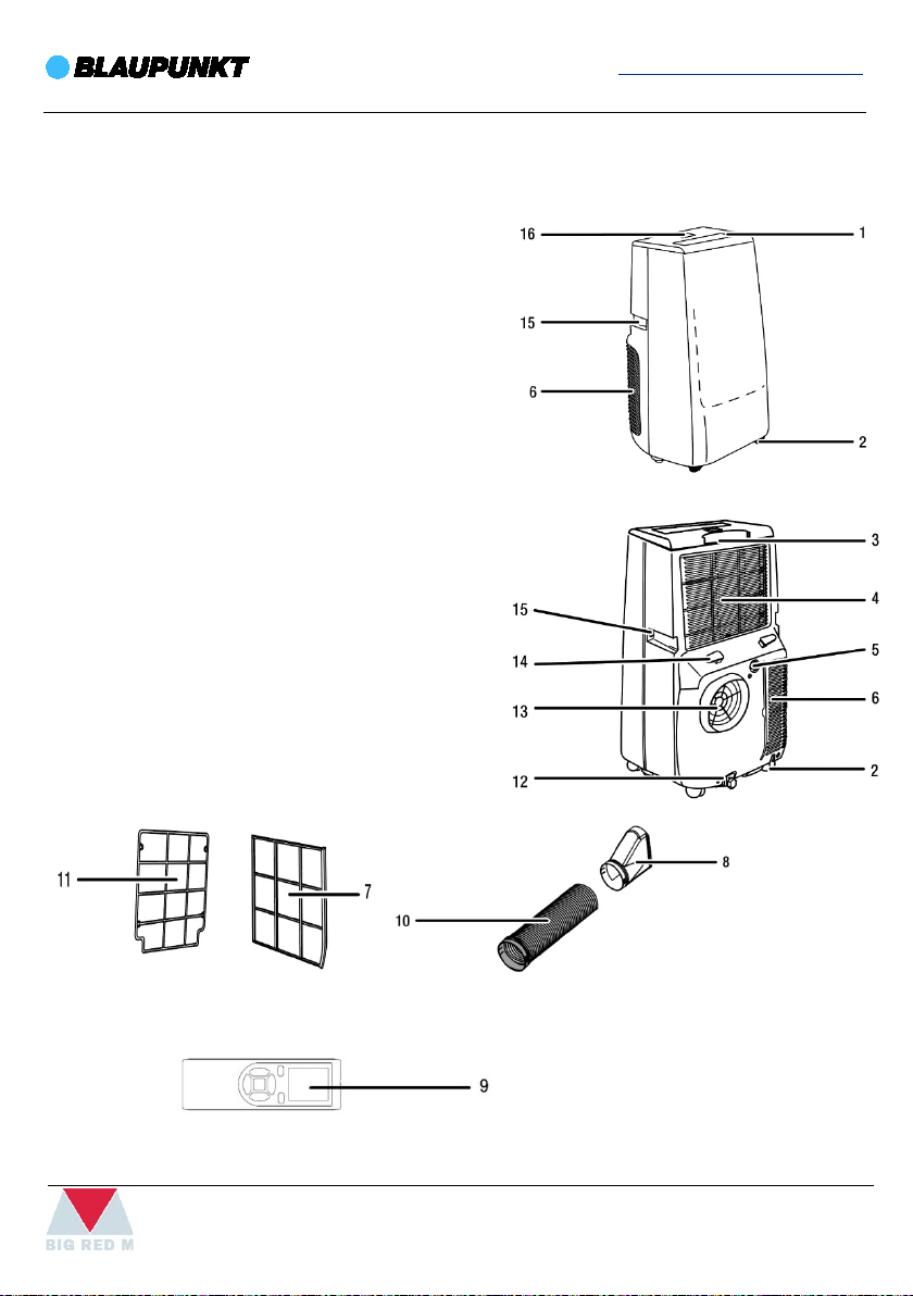
DESCRIPTION
1. Deflector
2. Castors
3. Compartment for remote control
4. Intake grill with EVA air filter
5. Condensate water drain
6. Intake grill with CON air filter
7. CON air filter
8. Window adapter
9. Remote control
10. Air exhaust hose with air inlet
11. EVA air filter
12. Condensate water drain
13. Air exhaust hose housing
14. Power cable holder
15. Handle
16. Control panel
9
Page 10

www.blaupunkt.com
A12C
TRANSPORT AND STORAGE
If you store or transport the device improperly, the device may be damaged. Note the
information regarding transport and storage of the device.
TRANSPORT
To make the device easier to transport, it is fitted with castors.
Before transporting the device, observe the following:
• Switch the device off.
• Hold onto the mains plug while pulling the power cable out of the mains socket.
• Drain the remaining condensate from the device.
• Do not use the power cable to drag the device.
• Only wheel the device on a level and smooth surface.
After transporting the device, observe the following:
• Set up the device in an upright position after transport.
• Leave the device to rest for 12 to 24 hours, so the refrigerant can accumulate within the
compressor. Wait 12 to 24 hours before switching the device back on! Acting contrary
might lead to compressor damage and a malfunctioning device. If so, any warranty claims
will be voided.
STORAGE
Before storing the device, drain the remaining condensate from the device.
When the device is not being used, observe the following storage conditions:
• dry and protected from frost and heat
• in an upright position where it is protected from dust and direct sunlight
• with a cover to protect it from invasive dust if necessary
Place no further devices or objects on top of the device to prevent it from being damaged.
Remove batteries from the remote control.
10
Page 11
www.blaupunkt.com
A12C
ASSEMBLY AND INSTALLATION
SCOPE OF DELIVERY
• 1 x Device
• 1 x Air exhaust hose
• 1 x Air inlet
• 1 x Window adapter
• 1 x Window slider
• 1 x Remote control
• 1 x Manual
UNPACKING THE DEVICE
1. Open the cardboard box and take the device out.
2. Completely remove the packaging.
3. Fully unwind the power cable. Make sure that the power cable is not damaged and that
you do not damage it during unwinding.
START-UP
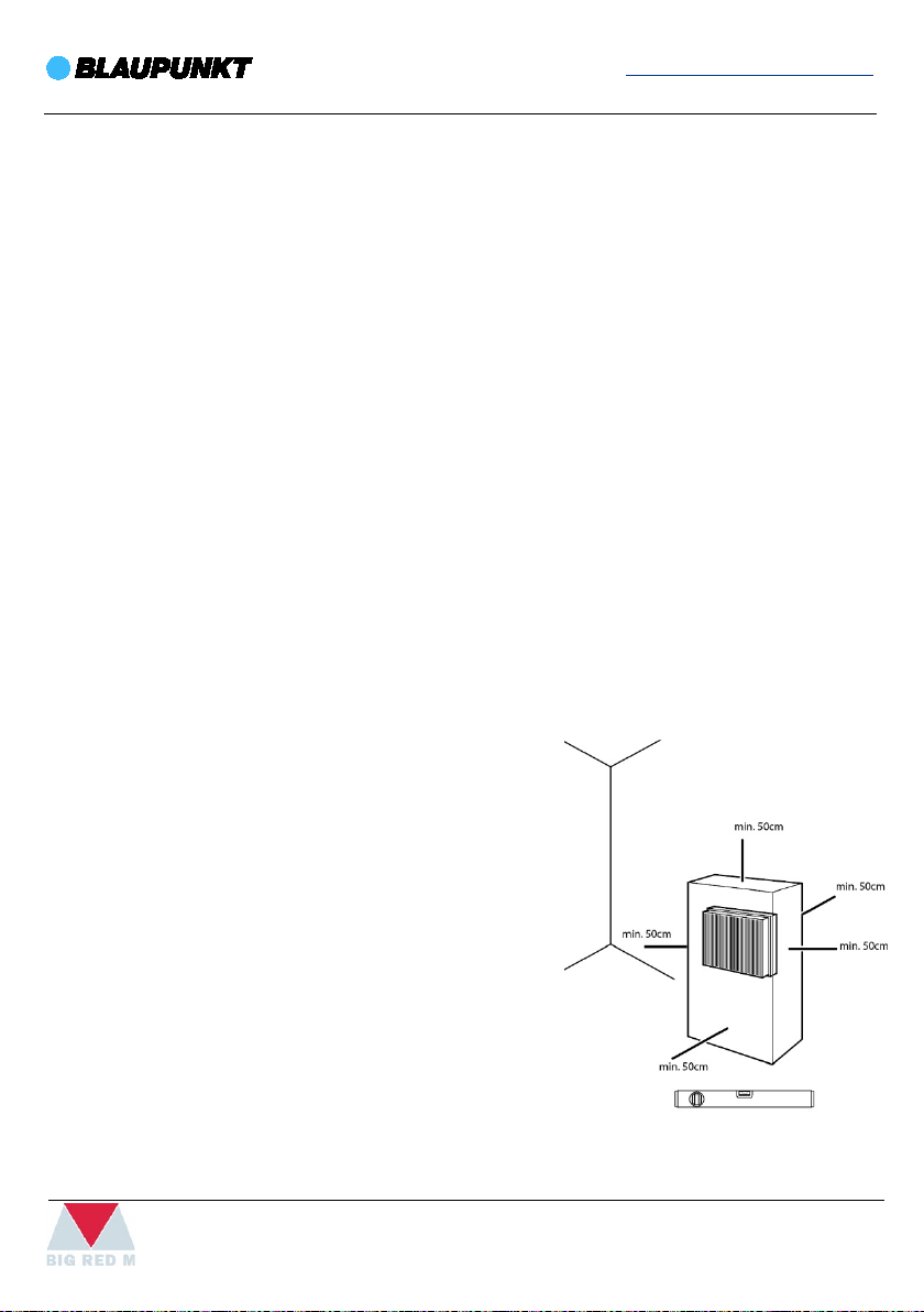
• When positioning the device, observe the
• Before restarting the device, check the condition
• Set the device up in an upright and stable
• Do not create tripping hazards when laying the
• Keep air inlets and outlets as well as the air
• Make sure that no curtains or other objects
minimum distance 50 cm from walls or other
objects.
of the power cable. If there are doubts, contact
the customer service.
position.
power cable or other electric cables, especially
when positioning the device in the middle of the
room.
exhaust hose housing free.
interfere with the air flow.
11
Page 12
www.blaupunkt.com
A12C
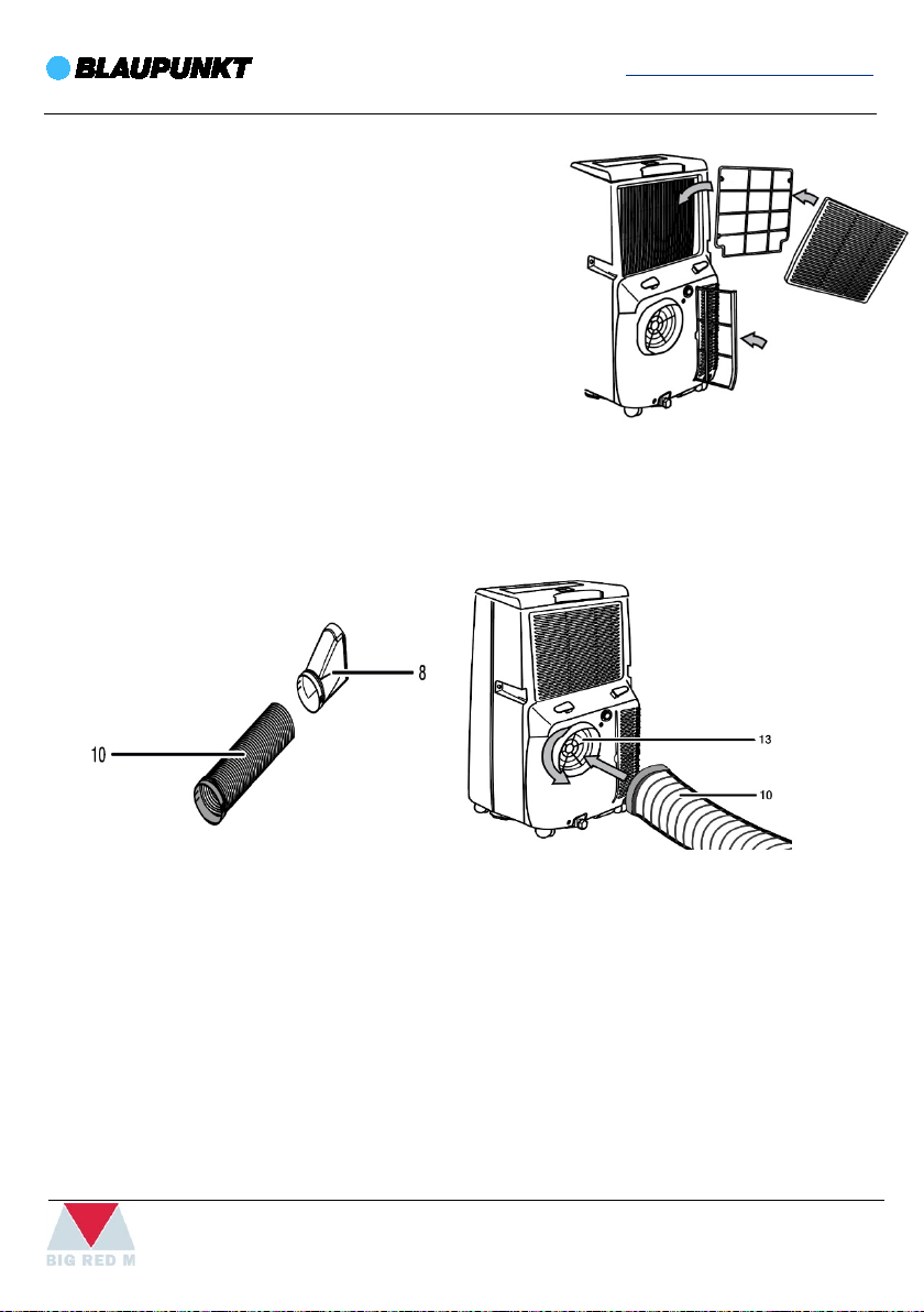
INSERTING THE AIR FILTER
• Do not operate the device without an inserted air
filter. Without an air filter the inside of the device
will be heavily contaminated, which could reduce
the performance and result in damage to the
device.
• Make sure that the air filters are installed before
switching the device on.
CONNECTING THE AIR EXHAUST HOSE
1. Connect the window adapter (8) to one end of the air exhaust hose (10), connect the air
inlet to the other end of the air exhaust hose.
2. Screw the air exhaust hose (10) with air inlet into the air conditioner's air exhaust hose
housing (13) in the direction of the arrow (see figure).
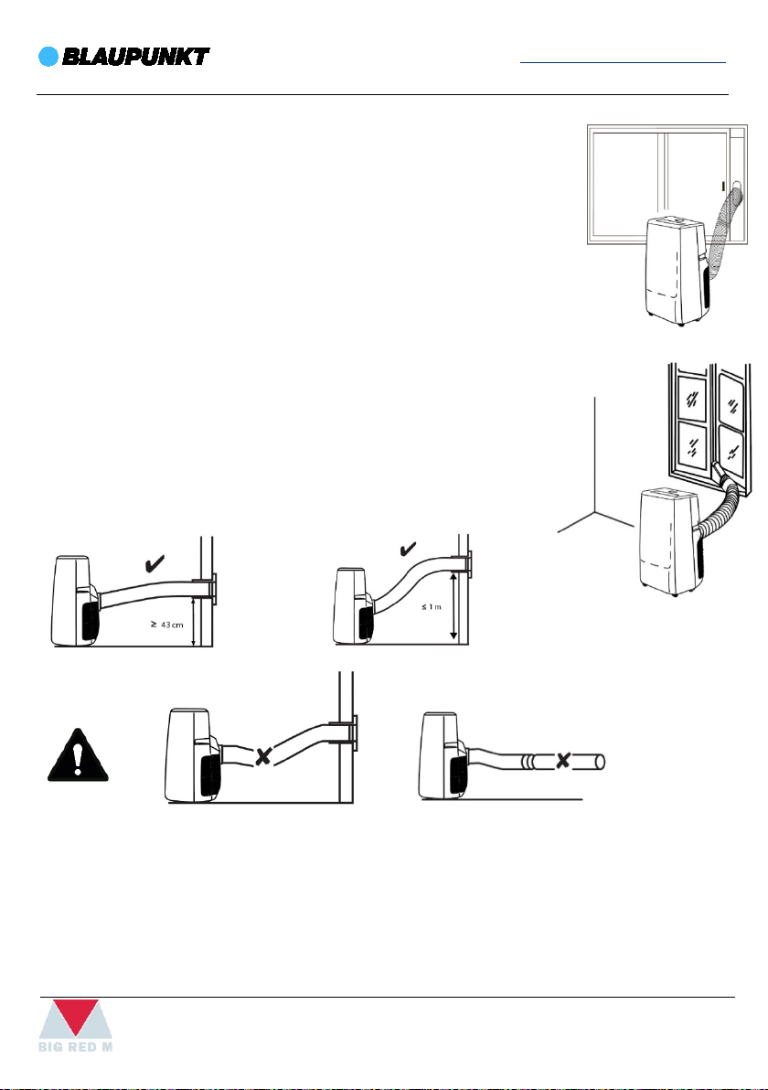
EXHAUSTING HOT AIR
• The exhaust air coming from the device contains waste heat from the room to be cooled.
For this reason it is recommended to discharge the exhaust air to the outside.
• The end of the air exhaust hose can be fed through the open window. If required, secure
the open window with the corresponding means, so that the end of the air exhaust hose
cannot shift.
• The end of the air exhaust hose can also be hooked into a tilted window. For this purpose
we recommend using a window seal (optional).
• Install the air exhaust hose inclined with the air direction.
12
Page 13
www.blaupunkt.com
A12C
HOW TO USE THE WINDOW SLIDER
• Affix the window slider in the window gap and adjust the length as
needed.
• Connect the end of the air exhaust hose with window adapter to
the window slider.
• Close the window until the Windows Slider is held securely.
FOR INSTALLING THE AIR EXHAUST HOSE PLEASE OBSERVE THE
FOLLOWING:
• Avoid kinks and bends in the air exhaust hose, as they would
lead to an accumulation of emitted humid air causing the
device to overheat and shut down.
• The dimensions of the air exhaust hose were especially made
to fit the device. Do not replace or extend the hose, it could
cause a malfunction.
• Keep the air exhaust hose as short as possible.
CONNECTING THE POWER CABLE
• Insert the mains plug into a properly secured mains socket.
13
Page 14
www.blaupunkt.com
A12C
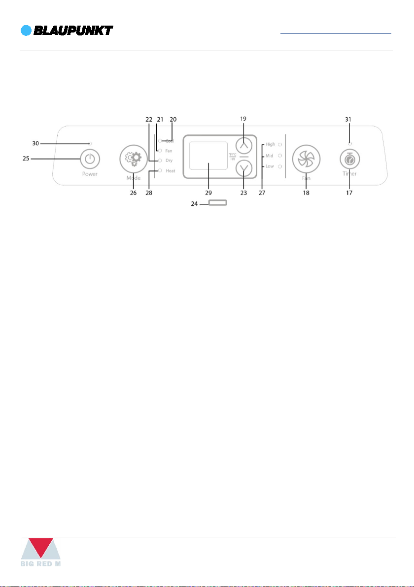
OPERATING FROM THE CONTROL PANEL
17. Timer button: Switching the timer function on or off.
18. Fan button: Setting the 3 fan speeds: high, medium and low.
19. Increase button UP: Increasing the target temperature for cooling: value range from 16 °C
to 30 °C. Increasing the number of hours for the timer: 1 to 24 hours.
20. Cool mode indicator
21. Fan mode indicator
22. Dry mode indicator
23. Decrease button DOWN: Reducing the target temperature for cooling: value range from
16 °C to 30 °C. Reducing the number of hours for the timer: 1 to 24 hours.
24. Remote control transmitter /receiver: Communication between device and remote
control.
25. Power button: Switching the device on or off.
26. Mode button: Selection button for the mode of operation.
27. Fan speed indicator: Indicating the 3 fan speeds: high, medium and low.
28. Heat mode indicator (Only the heat pump model has this function.)
29. Segment display: Display of current room temperature. Display of target temperature.
Display of timer. Display of error codes.
30. Wi-Fi indicator (Only Wi-Fi model has this function.)
31. Timer indicator
14
Page 15

www.blaupunkt.com
A12C
SWITCHING THE DEVICE ON
1. Once you have completely installed the device as described in the chapter “Assembly
and Installation” you can switch it on.
2. Press the Power button (25). The device switches on.
3. Select the desired operating mode.
The device switches off automatically when the condensation tank is full. FL appears in the
segment display (29) and an accoustic signal is emitted.
COOL MODE
1. In cool mode the room will be cooled down to a certain preselected temperature. The fan
speed can be set as required. Press the Mode button (26) until the cooling mode
indicator (20) appears on the control panel.
2. Press the UP button (19) for increasing or the DOWN button (23) for reducing the
temperature to set the desired target temperature. The target temperature is indicated
on the display (29).
DRY MODE
1. In dry mode the humidity level in the room is reduced. The temperature cannot be
adjusted and the fan runs at the lowest speed level.
2. If you use the device for an extended period of time or you don't want to empty the tank
all the time, you can connect a condensation drain hose to the condensate water drain.
3. The compressor only starts at a room temperature of ≥ 17 °C.
4. Press the Mode button (26) until the dry mode indicator (22) appears on the control
panel. The current room temperature is indicated on the segment display (29).
5. If the device is operated in a very humid environment, the accumulating condensate
must be drained at regular intervals.
FAN MODE
1. In Fan mode the room air is circulated, it will neither be cooled nor dehumidified.
2. Press the Mode button (26) until the fan mode indicator (21) appears on the control
panel.
3. Press the Fan button (18) to set the desired fan speed. The selected fan speed (27) is
displayed. The current room temperature is indicated on the segment display (29).
15
Page 16

www.blaupunkt.com
A12C
4. SETTING THE TIMER
The timer has two modes of operation:
1. Automatic switch-on upon expiry of a preset number of hours.
2. Automatic switch-off upon expiry of a preset number of hours.
The number of hours can range from 1 to 24 and can be adjusted in increments of 1 h. Do not
leave the operating device unattended in a freely accessible room with an activated timer.
AUTOMATIC SWITCH-ON
The device is switched off.
1. Press the Timer button (17).
2. Press the UP (19) or DOWN button (23) until the desired number of hours is displayed.
The number of hours flashes on the segment display (29).
3. Wait for approx. 5 seconds in order to save the setting. The timer setting equals the
desired number of hours. The hours are indicated on the segment display (29). The device
starts in the previously selected operating mode after the set time has elapsed.
4. The settings are retained, even if the power supply is disconnected.
5. Manually switching the device on disables the automatic switch-on function.
6. If you select 0 hours, the timer will be off.
AUTOMATIC SWITCH-OFF
The device is switched on.
1. Press the Timer button (17).
2. Press the UP (19) or DOWN button (23) until the desired number of hours is displayed.
The number of hours flashes on the segment display (29).
3. Wait for approx. 5 seconds in order to save the setting. The display changes back to the
previous indication. The timer indicator (31) appears on the control panel. The timer
setting equals the desired number of hours. The device switches off after the set period of
time.
16
Page 17

www.blaupunkt.com
A12C
SLEEP MODE
Sleep mode can only be activated in cooling mode.
Sleep mode comes with the following settings:
• After 2 hours the preset temperature is increased by 1 °C.
• After another 2 hours the temperature is again increased by 1 °C, thus the preset
temperature is increased by a total of 2 °C within 4 hours. Afterwards the temperature is
kept at this value.
• The fan speed is automatically lowered to the min. level and cannot be changed
manually. The swing function can be switched on via the remote control, if required.
To activate sleep mode, please proceed as follows:
1. Press the Mode button (26) until the cooling mode indicator (20) appears on the control
panel.
2. Simultaneously press the Timer (17) and UP (19) buttons. The sleep mode indication “SL”
appears on the segment display (29). The fan speed is automatically adjusted to the
lowest level.
3. To switch the sleep mode off press the Timer (17) and UP (19) buttons simultaneously
once again. Fan speed and temperature will return to the level that was set before sleep
mode was activated.
17
Page 18
www.blaupunkt.com
A12C
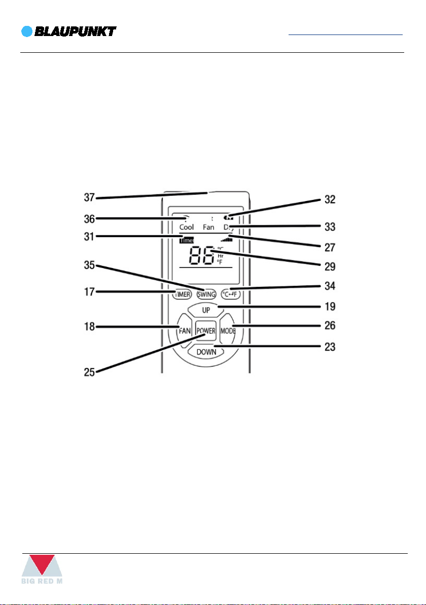
REMOTE CONTROL
All settings of the device can also be made using the remote control included in the scope of
delivery. Insert suitable batteries in the remote control.
DESCRIPTION
17. Timer button: Switching the timer function on or off: 1 to 24 hours.
18. Fan button: Setting the 3 fan speeds: high, medium and low.
19. Increase button UP: Increasing the target temperature for cooling: value range from 16 °C
to 30 °C. Increasing the number of hours for the timer: 1 to 24 hours.
23. Decrease button DOWN: Reducing the target temperature for cooling: value range from
16 °C to 30 °C. Reducing the number of hours for the timer: 1 to 24 hours.
25. Power button: Switching the device on or off.
26. Mode button: Selection button for the mode of operation.
27. Fan speed indicator: Indicating the 3 fan speeds: high, medium and low.
29. Segment display: Display of current room temperature. Display of target temperature.
Display of timer. Display of error codes.
18
Page 19
www.blaupunkt.com
A12C
31. Timer indicator
32. Battery indicator: Charging status of the batteries for the remote control.
33. Operating mode indicator
34. °C / °F button: Switching temperature indication between °C and °F.
35. Swing button: Adjusting the position of the deflector.
36. Transmitter indicator: Indicates transmission to the device, when the button is pressed.
37. Remote control transmitter /receiver: Communication between device and remote
control.
After a longer period of non-use, the remote control will switch to standby mode. Standby
mode can be terminated by pressing the Power button on the remote control. Please note
that the device automatically takes over the current settings from the remote control.
19
Page 20

www.blaupunkt.com
A12C
CHANGING THE UNIT °C / °F
The temperature in the segment display (29) can be indicated in °C or °F.
Please proceed as follows to change the temperature unit:
1. Simultaneously press the UP (19) and DOWN (23) buttons. Alternatively you can press the
°C / °F button (34) on the remote control. The displayed temperature is converted to the
other unit.
SWING FUNCTION
The Swing function can be activated via the remote control or directly at the device. Using the
Swing function, you can adjust the position of the deflector or activate continuous movement
of deflector.
1. Simultaneously press the Timer (17) and Fan (18) buttons or press the Swing button (35)
on the remote control. The deflector moves up and down continuously.
2. Press the Timer (17) and Fan (18) buttons simultaneously once again or press the Swing
button (35) on the remote control to stop the deflector in a certain position or to switch
the Swing function off.
AUTOMATIC DEFROST
At low ambient temperatures, ice may form at the evaporator. The device will then carry out
an automatic defrost. The automatic defrost indication E4 appears on the segment display
(29) and disappears again, when automatic defrosting is finished. The compressor switches off
and the fan keeps running until defrosting is completed. The duration of the defrost process
can vary. Do not switch off the device during automatic defrost. Do not remove the mains
plug from the mains socket.
20
Page 21
www.blaupunkt.com
A12C
MAINTENANCE AND CLEANING
ACTIVITIES REQUIRED BEFORE STARTING MAINTENANCE
WARNING OF ELECTRICAL VOLTAGE
• Do not touch the mains plug with wet or damp hands.
• Switch the device off.
• Hold onto the mains plug while pulling the power cable out of the
mains socket.
WARNING OF ELECTRICAL VOLTAGE
Tasks, which require the housing to be opened must only be carried out by authorised
specialist companies.
CLEANING THE HOUSING
Clean the housing with a soft, damp and lint-free cloth. Ensure that no moisture enters the
housing. Protect electrical components from moisture. Do not use any aggressive cleaning
agents such as cleaning sprays, solvents, alcohol-based or abrasive cleaners.
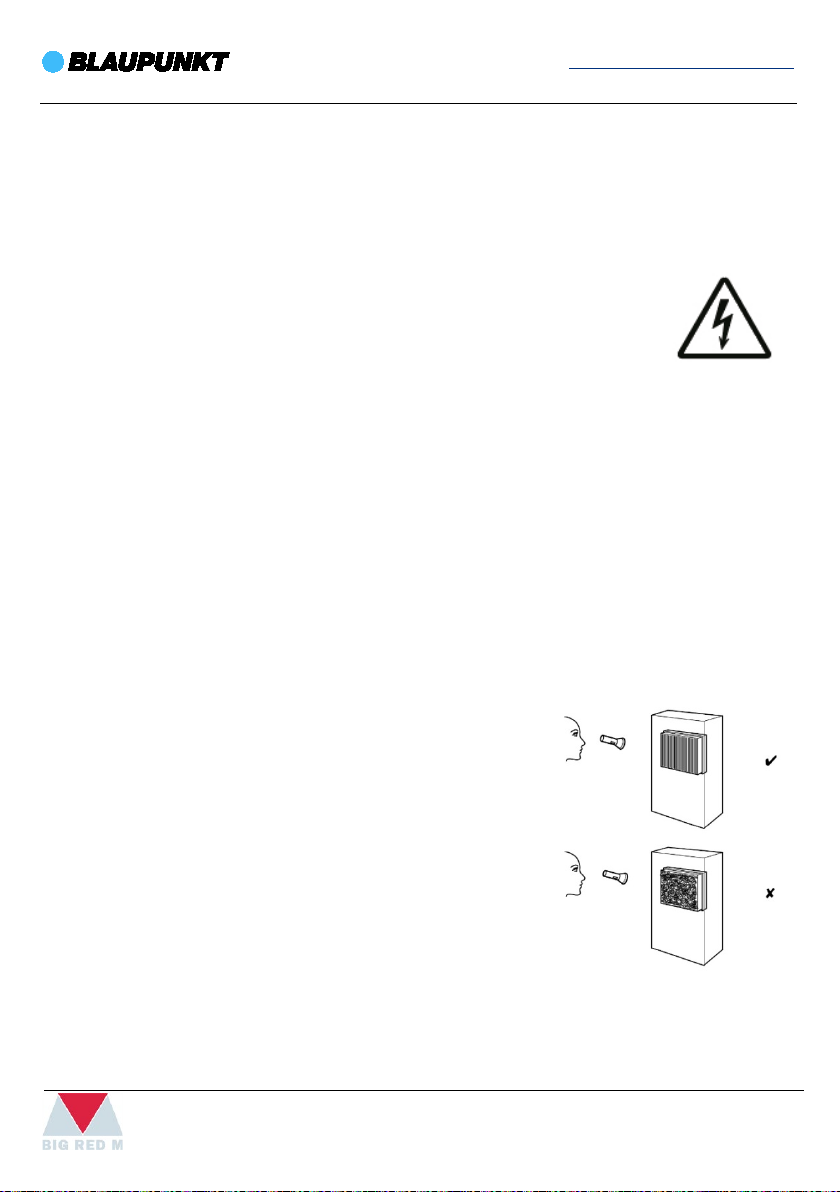
VISUAL INSPECTION OF THE INSIDE OF THE DEVICE FOR DIRT
1. Remove the air filter.
2. Use a torch to illuminate the openings of the device.
3. Check the inside of the device for dirt.
4. If you see a thick layer of dust, the inside of the device
must be cleaned by a specialist company for cooling
and air conditioning.
5. Put the air filter back in.
21
Page 22
www.blaupunkt.com
A12C
REFRIGERANT CIRCUIT
The entire refrigerant circuit is a maintenance-free, hermetically sealed system and may only
be maintained or repaired by specialist companies for cooling and air conditioning.
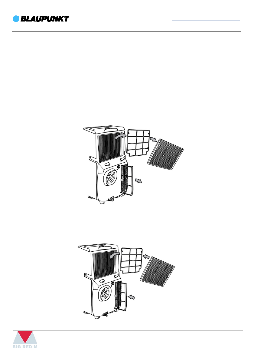
CLEANING THE AIR FILTER
The air filters have to be cleaned, as soon as they are dirty, at least once a week.
Ensure that the air filters are neither worn nor damaged. The corners and edges of the air
filters must not be deformed or rounded. Before reinserting the air filters, make sure that they
are undamaged and dry.
1. Remove the air filters from the device.
2. Clean the filters using a slightly damp, soft, lint-free cloth. If the filters are heavily
contaminated, clean them with warm water mixed with a neutral cleaning agent.
3. Allow the filters to dry completely. Do not put any wet filters into the device.
4. Reinsert the air filters into the device.
22
Page 23
www.blaupunkt.com
A12C
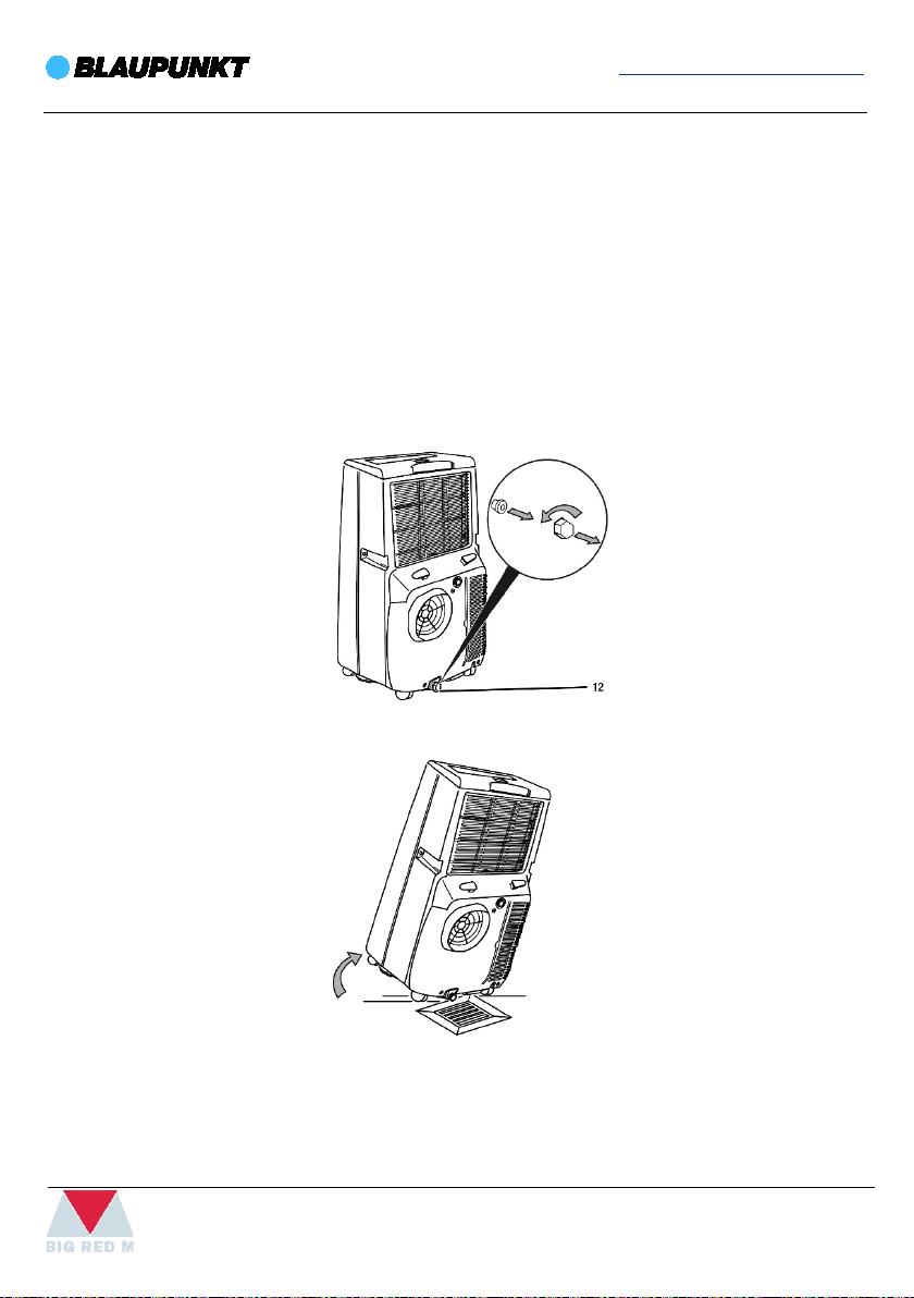
CONDENSATE WATER MANUAL DRAINING
In cool and dry mode condensate is formed, which is mostly discharged via the exhaust air.
The remaining condensate is collected in a container within the housing. The condensate
ought to be drained regularly. If too much condensate accumulates, the device switches off
and indicates this via the FL indication on the segment display (29).
1. Carefully transport or wheel the device to a suitable location for discharging the
condensate or position a suitable collection container under the condensate water drain
(12).
2. Unscrew the sealing cap from the condensate water drain (12).
3. Remove the rubber plug.
4. Slightly tilt or incline the device towards the drain or collection container.
5. Let the condensate run off completely.
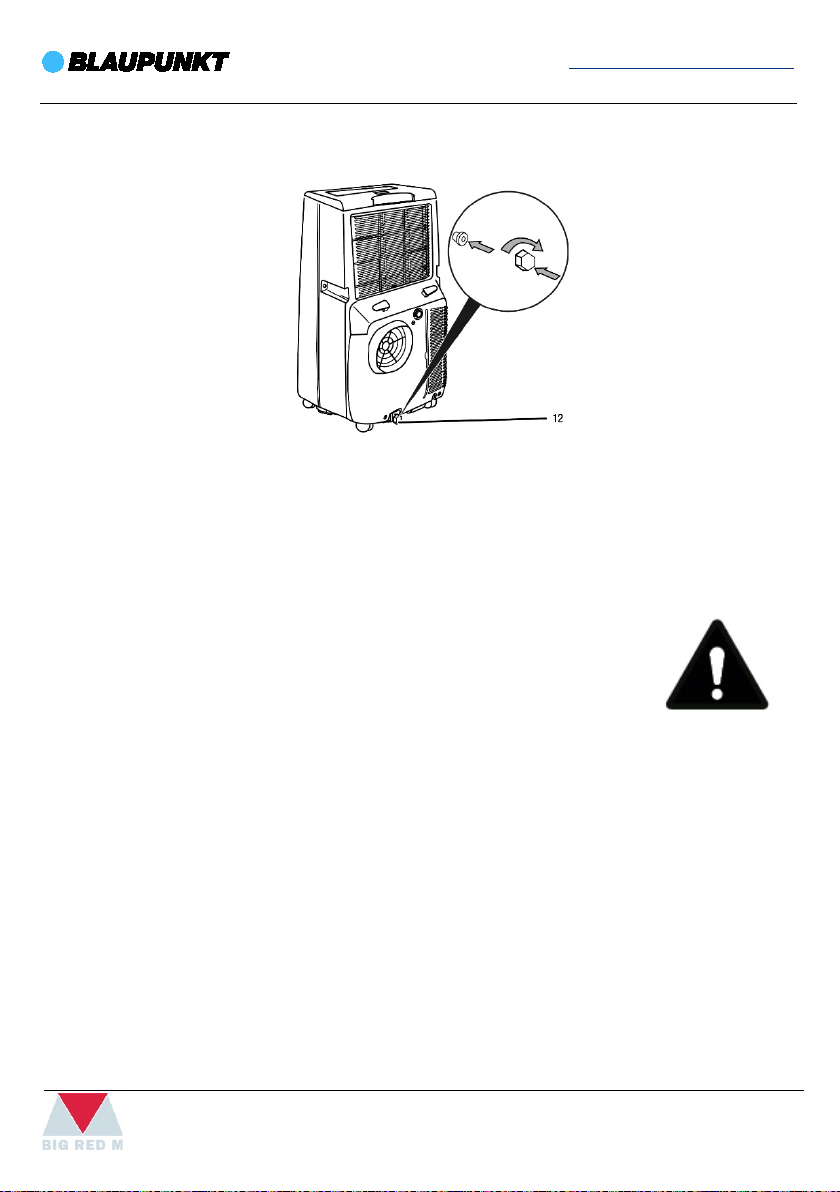
6. Reattach the rubber stopper to the condensate water drain (12). Check the rubber
stopper for tight fit.
23
Page 24
www.blaupunkt.com
A12C
7. Screw the sealing cap onto the condensate water drain (12).
The FL indication on the segment display (29) will go out, as soon as the condensate has been
drained.
ACTIVITIES REQUIRED AFTER MAINTENANCE
If you want to continue using the device:
• Leave the device to rest for 12 to 24 hours, so the refrigerant can
accumulate within the compressor. Wait 12 to 24 hours before
switching the device back on! Acting contrary might lead to
compressor damage and a malfunctioning device. If so, any
warranty claims will be voided.
• Reconnect the device to the mains.
24
Page 25
www.blaupunkt.com
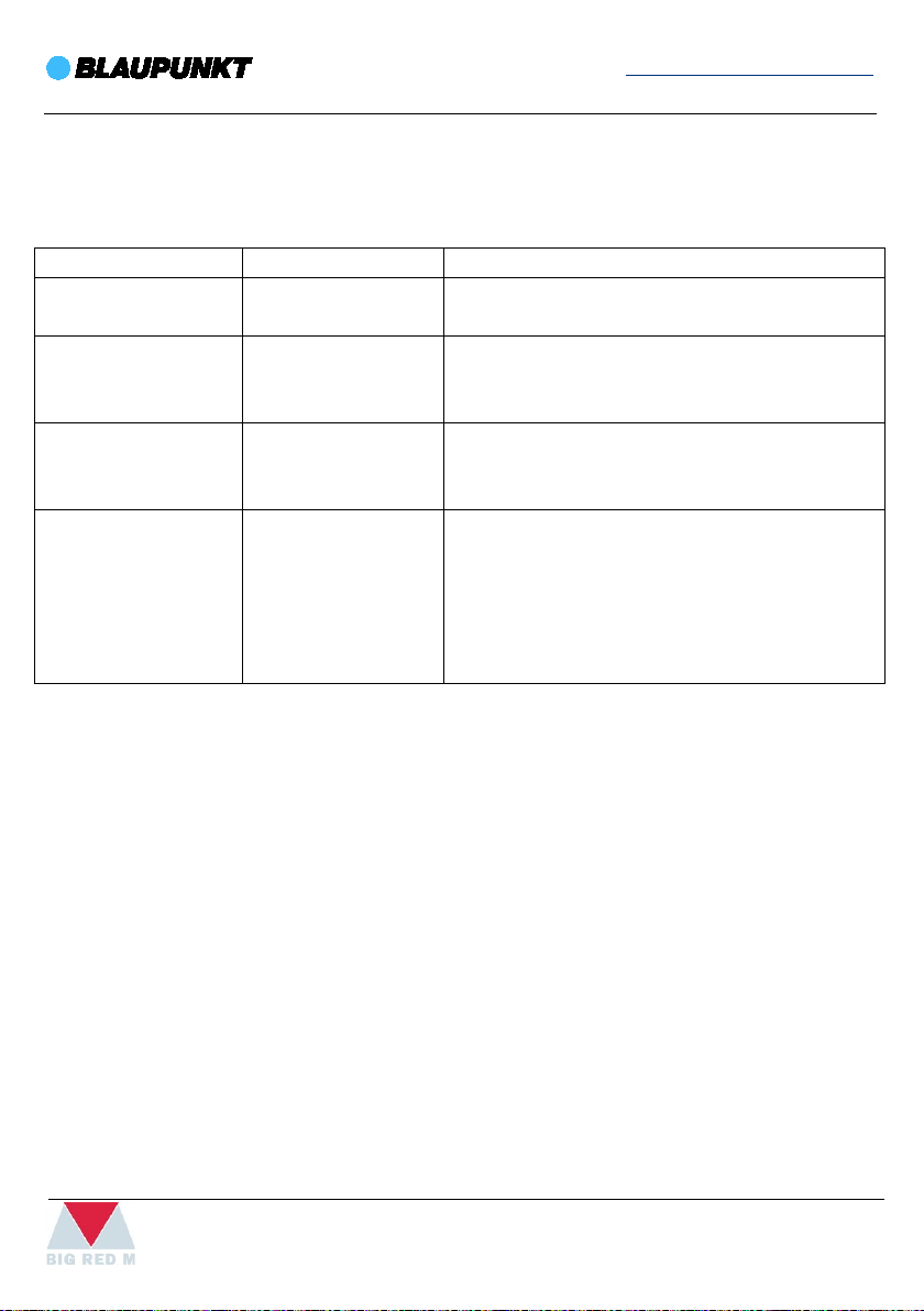
Error code
Cause
Solution
FL
Condensation tank
Discharge condensate according to the
E1
Defective exhaust
Disconnect the device briefly from the mains.
E2
Defective room
Disconnect the device briefly from the mains.
E4
Automatic defrost
At low ambient temperatures, ice may form at
A12C
SELF-DIAGNOSIS
The following error messages can be displayed on the segment display.
full
air temperature
sensor
temperature sensor
“Condensate water manual draining” chapter.
Should the error still be displayed after the
restart, please contact the customer service.
Should the error still be displayed after the
restart, please contact the customer service.
the evaporator. The device will then carry out
an automatic defrost. The duration of the
defrost process can vary. Do not switch off the
device during automatic defrost. Do not
remove the mains plug from the mains socket.
25
Page 26

www.blaupunkt.com
PROBLEM
SOLUTION
The device does not
•
not starting, have the electrics checked by specialist company.
The device works with
•
temperature, if it is higher than the room temperature.
The device is loud or
•
The compressor does
•
provided with an internal protection against direct restart.
A12C
TROUBLESHOOTING
Check the power connection.
start
reduced or no cooling
capacity
• Check the power cable and mains plug for damages.
• Check the on-site fusing.
• Observe the operating temperature.
• Check the filling level of the condensation tank and empty, it if
necessary. The FL indication (condensation tank full) must not
light up.
• Wait for 10 minutes before restarting the device. If the device is
Check whether cooling mode is selected.
• Check the proper fit of the air exhaust hose. In case of kinks,
bends or blockage in the hose, exhaust air cannot be
discharged. Clear the way for the exhaust air.
• Check the position of the deflector. It should be opened to the
maximum.
• Check the air filter(s) for dirt. If necessary, clean or replace the air
filter(s).
• Check the minimum distance to walls or other objects. Position
the device a little more in the room's centre, if required.
• Check whether any windows and/or doors of the room are
open. If so, close them. The window for the air exhaust hose has
to remain open nonetheless.
• Check the temperature setting at the device. Reduce the set
Check whether the device is set up in a stable and upright
vibrates
not start
position.
Check whether the overheating protection of the compressor
has tripped. Disconnect the device from the mains and let it
cool down for approx. 10 minutes before reconnecting it.
• Check whether the ambient temperature equals the target
temperature (in cooling mode). The compressor will not switch
on unless the respective temperature is reached.
• The compressor may start up with a delay of 3 min, as it is
26
Page 27

www.blaupunkt.com
The device gets very
•
cooling and air conditioning.
The device does not
•
correct polarity and change them, if required.
A12C
Check the air inlets and air filters for dirt. Remove external dirt.
warm, is loud or loses
power
respond to the
infrared remote
control
Wait for at least 3 minutes after maintenance and repair work. Only then switch the device
back on.
• From the outside, check the device for dirt. If the inside of the
device is dirty, have it cleaned by a specialist company for
Check whether the distance between remote control and
device is too large and reduce, it if necessary.
• Make sure there are no obstacles, such as furniture or walls,
between the device and the remote control. Ensure visual
contact between device and remote control.
• Check the charging status of the batteries and change them, if
required.
• If the batteries have only just been changed, check them for
27
Page 28

www.blaupunkt.com
A12C
WARRANTY
Dear Customer,
all our products are subject to strict quality control before they are sold. However, if the device
does not work as it should, we sincerely regret it. In this case, we kindly request you to contact
our customer service. Our employees will be happy to help.
This device has a warranty period of 2 years from the date of purchase. During the warranty
period, the manufacturer accepts full responsibility for failures that are obviously due to
material or construction defects. If such defects occur, the device will be repaired or replaced
as necessary. The warranty period of 2 years does not start at this moment again, but it
continues until 2 years after the date of purchase. The guarantee is provided on the basis of a
proof of purchase. The warranty will not be valid when the damage to the appliance is caused
by wrong use, not following the instructions or repairs executed by a third party.
The warranty and liability of the supplier and manufacturer lapse automatically in the
following cases:
• If the instructions in this manual have not been followed.
• In case of incorrect connection, e.g. too high or too low voltage.
• In case of improper, rough or abnormal use.
• In case of insufficient or incorrect maintenance.
• In case of repair or alteration of the device by the consumer or unauthorized third parties.
• If the customer used parts or accessories that are not recommended or provided by the
manufacturer.
28
Page 29

www.blaupunkt.com
Mains voltage
see rating label
Maximum absorbed power in air conditioning
..
Refrigerant
..
Cooling capacity
..
Protection degree
IPX0
Temperature of room in air conditioning
17°C - 35°C (Cool)
17°C - 35°C (Dry)
Width
431 mm
Height
725 mm
Depth
370 mm
A12C
TECHNICAL SPECIFICATIONS
LIMIT CONDITIONS
SIZE OF APPLIANCE
29
Page 30

www.blaupunkt.com
A12C
30
Page 31

www.blaupunkt.com
A12C
Mobiles Klimagerät
Arrifana 12
BAC-PO-0012-C02D
Bedienungsanleitung
Mateko Sp. z o.o.
ul. Przyleśna 17a
PL-05-126 Michałów-Grabina
e-mail: service@mateko.pl
www.blaupunkt.com
31
Page 32

www.blaupunkt.com
A12C
WICHTIGE SICHERHEITSVORKEHRUNGEN
Verwenden Sie dieses Gerät nur wie in dieser Bedienungsanleitung beschrieben. Das Ziel
dieser Bedienungsanleitung ist es, möglichst viele Eventualitäten abzudecken. Jedoch sollte
bei der Inbetriebnahme und Installation dieses Geräts, wie bei allen anderen elektrischen
Geräten, Vorsicht und gesunder Menschenverstand angewendet werden.
Dieses Gerät wurde zur Wohnraumklimatisierung entwickelt und darf nicht für andere
Zwecke verwendet werden.
Die Eigenschaften dieses Geräts zu modifizieren oder zu verändern, ist in jeder Hinsicht
gefährlich.
Das Gerät muss in Übereinstimmung mit den nationalen Rechtsvorschriften zur Regelung
elektrischer Geräte und Anlagen installiert werden.
Wenn das Gerät repariert werden muss, wenden Sie sich an ein vom Hersteller autorisiertes
Service-Center. Reparaturen, die von unautorisiertem Personal durchgeführt werden,
können Gefahren verursachen.
Dieses Gerät darf ausschließlich von Erwachsenen verwendet werden.
Stellen Sie sicher, dass dieses Gerät niemals von Personen (einschließlich Kindern) mit
psychischen, physischen oder sensorischen Beeinträchtigungen oder mit unzureichender
Erfahrung und Kenntnis verwendet wird. Es sei denn, es besteht eine direkte Aufsicht durch
jemanden, der für die Sicherheit dieser Personen verantwortlich ist. Kleine Kinder sollten
beaufsichtigt werden, um sicherzustellen, dass sie nicht mit dem Gerät spielen.
Das Gerät muss mit einem effizienten Erdungssystem verbunden sein. Stellen Sie sicher, dass
Ihr Stromkreis von einem qualifizierten Elektriker überprüft wurde.
Verwenden Sie keine Verlängerungskabel.
Ziehen Sie vor der Reinigung oder Wartung stets den Netzstecker aus der Steckdose.
Entfernen Sie das Gerät niemals vom Strom, indem Sie am Netzkabel ziehen.
Installieren Sie das Gerät nicht in Räumen, die Gas, Öl oder Schwefel enthalten. Installieren
Sie das Gerät nicht in der Nähe von Hitzequellen.
Halten Sie das Gerät mindestens 50 cm entfernt von entflammbaren Substanzen (Alkohol
etc.) oder unter Druck stehenden Behältern (bspw. Spraydosen).
Legen Sie weder schwere noch heiße Objekte auf der Oberfläche des Geräts ab.
Reinigen Sie den Luftfilter mindestens einmal pro Woche.
Vermeiden Sie die Verwendung von Heizgeräten in der Nähe der Klimaanlage.
32
Page 33

www.blaupunkt.com
Wichtige Informationen für die richtige Entsorgung des Produkts in Übereinstimmung mit
Am Ende seiner Verwendungsdauer, darf das Produkt nicht wie
A12C
Transportieren Sie das Gerät immer in aufrechter Position. Bevor Sie das Gerät umstellen,
leeren Sie den Innenkreislauf vollständig von Wasser. Nachdem Sie das Gerät umgestellt
haben, warten Sie mindestens 12 Stunden, bevor Sie es starten.
Wenn Sie das Gerät beiseitestellen, verwenden Sie zum Abdecken keine Plastiktüten.
Das Verpackungsmaterial ist wiederverwendbar. Wir empfehlen Ihnen deshalb, dieses in
speziellen Abfalltrennungsbehältern zu entsorgen.
Übergeben Sie das Gerät am Ende seiner Verwendungsdauer an eine spezielle Sammelstelle.
Wenn das Netzkabel beschädigt wurde, muss es durch den Hersteller oder ein autorisiertes
technisches Service-Center ersetzt werden, um eine elektrische Gefährdung auszuschließen.
Die mobile Klimaanlage ist ein kompaktes Gerät, das alle für den ordnungsgemäßen Betrirb
erfordlichen Elemente enthält. Einige von ihnen, wie z.B. ein Kompressor oder Ventilator,
geben Geräusche von sich, die während des Betriebs zu hören sind. Dies ist kein Zeichen für
einen Geräteausfall.
der EG-Richtlinie 2002/96/EC.
Siedlungsabfall entsorgt werden. Es muss zu einer speziellen lokalen
Sammelstelle für Abfalltrennung oder zu einem Händler, der einen solchen
Service bereitstellt, gebracht werden. Das separate Entsorgen eines
Haushaltsgeräts vermeidet mögliche negative Auswirkungen auf die
Umwelt und Gesundheit, die durch unsachgemäße Entsorgung entstehen,
und ermöglicht die Wiederherstellung der Ausgangswerkstoffe, um Energieund Ressourceneinsparungen zu erreichen. Als Erinnerung an die
Notwendigkeit, Haushaltsgeräte separat zu entsorgen, ist das Produkt mit
einer durchgestrichenen rollbaren Mülltonne gekennzeichnet.
ELEKTRISCHE ANSCHLÜSSE
Bevor Sie das Gerät in die Netzsteckdose einstecken, überprüfen Sie Folgendes:
Entspricht die Netzspannung dem angegebenen Wert des Typenschilds auf der Rückseite
des Geräts?
Eignen sich die Steckdose und Stromversorgung für das Gerät?
Passt die Netzsteckdose zum Stecker? Ersetzen Sie den Stecker, wenn dies nicht der Fall ist.
Ist die Netzsteckdose ordnungsgemäß geerdet? Die Nichtbeachtung dieser wichtigen
Sicherheitshinweise entbindet den Hersteller von jeglicher Haftung.
33
Page 34

www.blaupunkt.com
A12C
SPEZIELLE INFORMATIONEN ZU GERÄTEN MIT DEM KÄLTEMITTEL R290
• Bitte lesen Sie alle Warnhinweise aufmerksam durch.
• Wenn Sie das Gerät abtauen und reinigen, dürfen Sie nur solche Werkzeuge verwenden,
die vom Hersteller empfohlen werden.
• Das Gerät muss an einem Standort aufgestellt werden, an dem es keine ständigen
Zündquellen (z. B.: offenes Feuer, im Betrieb befindliche Gas- oder Elektrogeräte) gibt.
• Durchstechen und verbrennen Sie das Gerät nicht.
• Kältemittel können geruchlos sein.
• Das Gerät muss an einem Standort aufgestellt, verwendet und gelagert werden, der
größer als 13 m² ist.
• R290 ist ein Kältemittel, dass die europäischen Umweltrichtlinien erfüllt. Durchstechen
Sie keinen Teil des Kühlkreislaufs.
• Wenn das Gerät an einem nicht belüfteten Standort aufgestellt, betrieben oder gelagert
wird, muss der Raum derart gestaltet sein, dass er einer Ansammlung von
Kältemittellecks vorbeugt, die zu einem Feuer- oder Explosionsrisiko durch Entzündung
des Kältemittels durch elektrische Heizgeräte, Öfen oder andere Zündquellen führen
können.
• Das Gerät muss so gelagert werden, dass es nicht zu einem mechanischen Defekt
kommen kann.
• Wartungsarbeiten am Kühlkreislauf dürfen nur von Personen vorgenommen werden, die
die entsprechende Zertifizierung von einer anerkannten Organisation erhalten haben,
die sicherstellt, dass mit dem Kältemittel sachgerecht gemäß der Richtlinie eines
Branchenverbands gehandhabt wird.
• Reparaturen dürfen nur auf der Grundlage von Empfehlungen des Herstellers
durchgeführt werden.
• Wartungs- und Reparaturarbeiten, die Unterstützung durch anderes qualifiziertes
Fachpersonal erfordern, dürfen nur unter Aufsicht einer Person durchgeführt werden, die
im Umgang mit entzündlichen Kältemitteln geschult ist.
34
Page 35

www.blaupunkt.com
A12C
PRODUKTBESCHREIBUNG
1. Luftauslassgitter
2. Rollen
3. Fach für Fernbedienung
4. Lufteintrittsgitter mit EVA-Luftfilter
5. Kondenswasserabfluss
6. Lufteintrittsgitter mit CON-Luftfilter
7. CON-Luftfilter
8. Fensterausgang
9. Fernbedienung
10. Abluftschlauch mit Schlaucheinlass
11. EVA-Luftfilter
12. Kondenswasserabfluss
13. Abluftschlaucheingang
14. Netzkabelhalterung
15. Griff
16. Bedienfeld
35
Page 36

www.blaupunkt.com
A12C
TRANSPORT UND LAGERUNG
Wenn Sie das Gerät unsachgemäß lagern oder transportieren, kann das Gerät beschädigt
werden. Beachten Sie die Informationen zum Transport und zur Lagerung des Geräts.
TRANSPORT
Das Gerät ist zum leichteren Transport mit Transportrollen versehen.
Beachten Sie folgende Hinweise vor jedem Transport:
• Schalten Sie das Gerät aus.
• Ziehen Sie das Netzkabel aus der Netzsteckdose, indem Sie es am Netzstecker anfassen.
• Entleeren Sie das restliche Kondensat aus dem Gerät.
• Benutzen Sie das Netzkabel nicht als Zugschnur.
• Rollen Sie das Gerät nur auf ebenen und glatten Flächen.
Beachten Sie folgende Hinweise nach jedem Transport:
• Stellen Sie das Gerät nach dem Transport aufrecht auf.
• Lassen Sie das Gerät 12 bis 24 Stunden stehen, damit sich das Kältemittel im Kompressor
sammeln kann. Schalten Sie das Gerät erst nach 12 bis 24 Stunden wieder ein! Sonst
könnte der Kompressor beschädigt werden und das Gerät nicht mehr funktionieren. Der
Garantieanspruch erlischt in diesem Fall.
LAGERUNG
Beachten Sie folgende Hinweise vor jeder Lagerung:
• Entleeren Sie das restliche Kondensat aus dem Gerät.
Halten Sie bei Nichtbenutzung des Geräts die folgenden Lagerbedingungen ein:
• trocken und vor Frost und Hitze geschützt
• in aufrechter Position an einem vor Staub und direkter Sonneneinstrahlung geschützten
Platz
• ggf. mit einer Hülle vor eindringendem Staub geschützt
• keine weiteren Geräte oder Gegenstände auf das Gerät stellen, um Beschädigungen am
Gerät zu vermeiden
• Batterien aus der Fernbedienung entfernen
36
Page 37

www.blaupunkt.com
A12C
MONTAGE UND INSTALLATION
LIEFERUMFANG
• 1 x Gerät
• 1 x Abluftschlauch
• 1 x Schlaucheinlass
• 1 x Fensterausgang
• 1 x Verlängerbare Querträger
• 1 x Fernbedienung
• 1 x Anleitung
GERÄT AUSPACKEN
1. Öffnen Sie den Karton und entnehmen Sie das Gerät.
2. Entfernen Sie die Verpackung vollständig vom Gerät.
1. Wickeln Sie das Netzkabel vollständig ab. Achten Sie darauf, dass das Netzkabel nicht
beschädigt ist, und beschädigen Sie es beim Abwickeln nicht.
INBETRIEBNAHME
• Beachten Sie bei der Aufstellung des Geräts die Mindestabstände 50 cm zu Wänden und
Gegenständen.
• Vor der Wiederinbetriebnahme des Geräts überprüfen
Sie den Zustand des Netzkabels. Bei Zweifeln an dessen
einwandfreiem Zustand rufen Sie den Kundendienst an.
• Stellen Sie das Gerät aufrecht und standsicher auf.
• Vermeiden Sie Stolperstellen beim Verlegen des
Netzkabels bzw. weiterer Elektrokabel, insbesondere bei
Aufstellung des Gerätes in der Raummitte.
• Achten Sie darauf, dass Lufteinlässe und Luftauslässe
sowie der Anschluss für den Abluftschlauch frei sind.
• Achten Sie darauf, dass Vorhänge oder andere
Gegenstände die Luftströmung nicht behindern.
37
Page 38

www.blaupunkt.com
A12C
LUFTFILTER EINSETZEN
• Betreiben Sie das Gerät nicht ohne eingesetzten
Luftfilter! Ohne Luftfilter wird das Geräteinnere stark
verschmutzt, dadurch kann die Leistung gemindert
und das Gerät beschädigt werden.
• Stellen Sie vor dem Einschalten sicher, dass die
Luftfilter installiert sind.
ABLUFTSCHLAUCH ANSCHLIESSEN
1. Verbinden Sie den Fensterausgang (8) mit einem Ende des Abluftschlauchs (10).
Verbinden Sie den Schlaucheinlass mit anderem Ende des Abluftschlauchs (10).
2. Schrauben Sie das Ende des Abluftschlauchs (10) mit dem Schlaucheinlass in
Pfeilrichtung (siehe nachfolgende Abbildung) in den Abluftschlaucheingang (13) des
Klimageräts.
38
Page 39

www.blaupunkt.com
A12C
ABLUFT ABLEITEN
• Die Abluft des Geräts enthält die Abwärme aus dem zu kühlenden Raum. Aus diesem
Grund ist es empfehlenswert, die Abluft ins Freie abzuführen.
• Das Ende des Abluftschlauchs kann durch das geöffnete Fenster geführt werden. Sichern
Sie das geöffnete Fenster ggf. mit entsprechenden Hilfsmitteln, damit das Ende des
Abluftschlauchs nicht verrutschen kann.
• Das Ende des Abluftschlauchs kann in ein gekipptes Fenster eingehängt werden. Hierfür
empfiehlt sich die Nutzung einer Fensterabdichtung (optional).
• Verlegen Sie den Abluftschlauch mit Steigung in Luftrichtung.
VERWENDUNG DES QUERTRÄGERS
• Bringen Sie Querträger im Fensterspalt an und justieren Sie die Länge nach Bedarf.
• Verbinden Sie das Ende des Abluftschlauchs mit dem Fensterausgang in dem Querträger.
• Schließen Sie das Fenster wieder, bis der Querträger festsitzt.
39
Page 40

www.blaupunkt.com
A12C
BEACHTEN SIE FOLGENDE HINWEISE FÜR DAS VERLEGEN DES ABLUFTSCHLAUCHS:
• Vermeiden Sie Knickstellen im Abluftschlauch. Knickstellen
führen zur Ansammlung von ausgestoßener feuchter Luft,
das Gerät überhitzt und schaltet ab.
• Der Abluftschlauch ist in seinen Abmessungen speziell auf
das Gerät abgestimmt. Ersetzen oder verlängern Sie ihn
nicht mit anderen Schläuchen. Dies könnte eine
Fehlfunktion des Geräts bewirken.
• Halten Sie den Abluftschlauch so kurz wie möglich.
NETZKABEL ANSCHLIESSEN
• Stecken Sie den Netzstecker in eine ordnungsgemäß abgesicherte Netzsteckdose.
40
Page 41

www.blaupunkt.com
A12C
BEDIENUNG MIT DEM BEDIENFELD
17. Taste Timer: Timer-Funktion ein- oder ausschalten: 1 bis 24 Stunden in 1h-Schritten.
18. Taste Fan: Lüftergeschwindigkeit einstellen in 3 Stufen High-Hoch, Mid-Mittel und Low-
Niedrig.
19. Taste Wert erhöhen UP: Zieltemperatur für die Kühlung erhöhen: Wertebereich von 16 °C
bis 30 °C. Stundenanzahl für den Timer erhöhen: 1 bis 24 Stunden in 1h Schritten.
20. Kühlungsanzeige
21. Anzeige für Ventilation
22. Anzeige für Entfeuchtung
23. Taste Wert verringern DOWN: Zieltemperatur für die Kühlung verringern: Wertebereich
von 16 °C bis 30 °C. Stundenanzahl für den Timer verringern: 1 bis 24 Stunden in 1hSchritten.
24. Sender / Empfänger Fernbedienung: Kommunikation zwischen Gerät und
Fernbedienung.
25. Taste Power: Ein-/Aus-Taste: Gerät ein- bzw. ausschalten.
26. Taste Mode: Wahltaste für die Betriebsart.
27. Anzeige Lüftergeschwindigkeit: High-Hoch, Mid-Mittel, Low-Niedrig.
28. Wärmeanzeige (Diese Funktion besitzt nur das Wärmepumpemodell.)
29. Segmentanzeige: Anzeige der aktuellen Raumtemperatur, Anzeige der gewünschten
Temperatur, Anzeige des Timers, Anzeige der Fehlercodes.
30. Anzeige für Wi-Fi (Diese Funktion besitzt nur das Modell mit Wi-Fi Steuerung.)
31. Anzeige Timer
41
Page 42

www.blaupunkt.com
A12C
GERÄT EINSCHALTEN
1. Nachdem Sie das Gerät, wie im Kapitel „Montage und Installation“ beschrieben,
betriebsbereit aufgestellt haben, können Sie es einschalten.
2. Drücken Sie die Taste Power (25). Das Gerät schaltet sich ein.
3. Wählen Sie die gewünschte Betriebsart aus.
Das Gerät schaltet automatisch ab, wenn der Kondensatbehälter voll ist. In der
Segmentanzeige (29) erscheint FL und ein akustisches Signal ertönt.
KÜHLUNG (COOL)
1. In der Betriebsart Kühlung wird der Raum bis zu einer voreingestellten Temperatur
heruntergekühlt. Die Lüftergeschwindigkeit kann beliebig eingestellt werden.
2. Drücken Sie die Taste Mode (26), bis die Kühlungsanzeige (20) im Bedienfeld erscheint.
3. Drücken Sie die Taste UP (19) zum Erhöhen oder die Taste DOWN (23) zum Verringern der
Temperatur, um die gewünschte Zieltemperatur einzustellen. Die Zieltemperatur wird in
der Segmentanzeige (29) angezeigt.
ENTFEUCHTUNG (DRY)
1. In der Betriebsart Entfeuchtung wird die Luftfeuchtigkeit im Raum reduziert. Die
Temperatur kann nicht verstellt werden und die Ventilation läuft auf der niedrigsten Stufe.
2. Wenn Sie das Gerät über einen längeren Zeitraum verwenden oder wenn Sie den Tank
nicht ständig leeren wollen, besteht die Möglichkeit, einen Kondensatablaufschlauch an
den Kondenswasserabfluss anzuschließen.
3. Der Kompressor startet erst bei einer Raumtemperatur ≥ 17 °C.
4. Drücken Sie die Taste Mode (26), bis die Anzeige für Entfeuchtung (22) im Bedienfeld
erscheint. Die aktuelle Raumtemperatur wird in der Segmentanzeige (29) angezeigt.
5. Wenn das Gerät in einer sehr feuchten Umgebung betrieben wird, sollten Sie das
anfallende Kondensat regelmäßig entleeren.
VENTILATION (FAN)
In der Betriebsart Ventilation zirkuliert die Raumluft und es findet keine Kühlung bzw.
Entfeuchtung statt.
1. Drücken Sie die Taste Mode (26), bis die Anzeige für Ventilation (21) im Bedienfeld
erscheint.
2. Drücken Sie die Taste Fan (18), um die gewünschte Lüftergeschwindigkeit einzustellen.
Die gewählte Lüftergeschwindigkeit (27) wird angezeigt. Die aktuelle Raumtemperatur
wird in der Segmentanzeige (29) angezeigt.
42
Page 43

www.blaupunkt.com
A12C
TIMER EINSTELLEN
Die Zeitschaltuhr hat zwei Funktionsweisen:
1. Automatisches Einschalten nach voreingestellter Stundenanzahl.
2. Automatisches Ausschalten nach voreingestellter Stundenanzahl.
Die Stundenanzahl kann zwischen 1 und 24 Stunden liegen und in1h-Schritten eingestellt
werden. Das Gerät sollte nicht unbeaufsichtigt in einem freizugänglichen Raum betrieben
werden, wenn der Timer aktiv ist.
AUTOMATISCHES EINSCHALTEN
Das Gerät ist ausgeschaltet.
1. Drücken Sie die Taste Timer (17).
2. Drücken Sie die Taste UP (19) oder DOWN (23), bis die gewünschte Stundenanzahl in der
Segmentanzeige (29) angezeigt wird. Die Stundenanzahl wird blinkend in der
Segmentanzeige (29) angezeigt.
3. Warten Sie ca. 5 Sekunden, um die Einstellung zu speichern. Der Timer ist auf die
gewünschte Stundenanzahl eingestellt. Die Stunden werden in der Segmentanzeige (29)
angezeigt. Das Gerät startet nach der eingestellten Zeit in der vorhereingestellten
Betriebsart.
4. Die Einstellungen bleiben bei einer Trennung von der Stromversorgung erhalten.
5. Das manuelle Einschalten des Gerätes deaktiviert das automatische Einschalten.
6. Wenn Sie die Stundenanzahl 0 wählen, ist der Timer ausgeschaltet.
AUTOMATISCHES AUSSCHALTEN
Das Gerät ist eingeschaltet.
1. Drücken Sie die Taste Timer (17).
2. Drücken Sie die Taste UP (19) oder DOWN (23), bis die gewünschte Stundenanzahl in der
Segmentanzeige (29) angezeigt wird. Die Stundenanzahl wird blinkend in der
Segmentanzeige (29) angezeigt.
3. Warten Sie ca. 5 Sekunden, um die Einstellung zu speichern. Die Segmentanzeige (29)
wechselt wieder zur vorherigen Anzeige. Die Anzeige Timer (31) erscheint im Bedienfeld.
Der Timer ist auf die gewünschte Stundenanzahl eingestellt. Das Gerät schaltet sich nach
der eingestellten Zeit aus.
43
Page 44

www.blaupunkt.com
A12C
SCHLAFMODUS
Der Schlafmodus kann nur in der Betriebsart Kühlung aktiviert werden.
Der Schlafmodus hat folgende Einstellungen:
• Die voreingestellte Temperatur wird nach 2 Stunden um 1 °C erhöht.
• Die Temperatur wird nach weiteren 2 Stunden erneut um 1 °C erhöht, also wird
insgesamt innerhalb von 4 Stunden die voreingestellte Temperatur um insgesamt 2 °C
erhöht. Danach bleibt die Temperatur auf diesem Wert.
• Die Lüftergeschwindigkeit wird automatisch auf die niedrigste Stufe eingestellt und kann
nicht manuell verändert werden. Die Swing-Funktion kann bei Bedarf über die
Fernbedienung eingeschaltet werden.
Um den Schlafmodus zu aktivieren, gehen Sie wie folgt vor:
1. Drücken Sie die Taste Mode (26), bis die Kühlungsanzeige (20) im Bedienfeld erscheint.
2. Drücken Sie die Taste Timer (17) und UP (19) gleichzeitig. Die Anzeige Schlafmodus SL
erscheint in der Segmentanzeige (29). Die Lüftergeschwindigkeit stellt sich automatisch
auf die niedrigste Stufe.
3. Um den Schlafmodus auszuschalten, drücken Sie erneut die Taste Timer (17) und UP (19)
gleichzeitig. Die Lüftergeschwindigkeit und die voreingestellte Temperatur stellt sich
automatisch auf die Stufe, die vor dem Schlafmodus eingestellt war.
44
Page 45

www.blaupunkt.com
A12C
FERNBEDIENUNG
Alle Einstellungen des Geräts können über die im Lieferumfang enthaltene Fernbedienung
vorgenommen werden. Setzen Sie passende Batterien in die Fernbedienung ein.
BESCHREIBUNG
17. Taste Timer: Timer-Funktion ein- oder ausschalten, 1 bis 24 Stunden in 1h-Schritten.
18. Taste Fan: Lüftergeschwindigkeit einstellen in 3 Stufen: High-Hoch, Mid-Mittel und LowNiedrig.
19. Taste Wert erhöhen UP: Zieltemperatur für die Kühlung einstellen: Wertebereich von 16
°C bis 30 °C, Stundenanzahl für den Timer einstellen: 1 bis 24 Stunden in 1h-Schritten.
23. Taste Wert verringern DOWN: Zieltemperatur für die Kühlung einstellen: Wertebereich
von 16 °C bis 30 °C, Stundenanzahl für den Timer einstellen: 1 bis 24 Stunden in 1hSchritten.
25. Taste Power: Ein-/Aus-Taste, Gerät ein- bzw. ausschalten.
26. Taste Mode: Wahltaste für die Betriebsart.
27. Anzeige Lüftergeschwindigkeit: High-Hoch, Mid-Mittel, Low-Niedrig.
45
Page 46

www.blaupunkt.com
A12C
29. Segmentanzeige: Anzeige der aktuellen Raumtemperatur, Anzeige der gewünschten
Temperatur, Anzeige des Timers, Anzeige der Fehlercodes.
31. Anzeige Timer
32. Anzeige Batterie: Ladestatus der Batterien für die Fernbedienung.
33. Anzeige Betriebsart: Cool-Kühlung, Fan-Ventilation, Dry-Entfeuchtung.
34. Taste °C / °F: Temperaturanzeige zwischen °C und °F umschalten.
35. Taste Swing: Stellung des Luftauslassgitters einstellen.
36. Anzeige Senden: Signalisiert das Senden an das Gerät bei Tastendruck.
37. Sender / Empfänger Fernbedienung: Kommunikation zwischen Gerät und
Fernbedienung.
Die Fernbedienung geht nach längerer Nichtbenutzung in den Standby-Betrieb. Durch
Drücken der Taste Power an der Fernbedienung wird der Standby-Betrieb beendet. Bitte
beachten Sie, dass das Gerät automatisch die aktuellen Einstellungen der Fernbedienung
übernimmt.
46
Page 47

www.blaupunkt.com
A12C
EINHEIT °C / °F UMSTELLEN
Die Temperatur in der Segmentanzeige (29) kann in °C oder °F dargestellt werden.
Gehen Sie wie folgt vor, um die Einheit der Temperatur umzustellen:
1. Drücken Sie die Tasten UP (19) und DOWN (23) gleichzeitig.
2. Alternativ können Sie die Taste °C / °F (34) auf der Fernbedienung drücken. Die
angezeigte Temperatur wird auf die andere Einheit umgestellt.
SWING-FUNKTION
Die Swing-Funktion kann direkt an dem Gerät oder über die Fernbedienung aktiviert werden.
Mit der Swing-Funktion können Sie die Stellung des Luftauslassgitters anpassen oder die
kontinuierliche Bewegung des Luftauslassgitters aktivieren.
1. Drücken Sie die Taste Timer (17) und Fan (18) gleichzeitig oder drücken Sie auf der
Fernbedienung die Taste Swing (35). Der Luftauslassgitter bewegt sich kontinuierlich auf
und ab.
2. Drücken Sie die Taste Timer (17) und Fan (18) erneut gleichzeitig bzw. drücken Sie auf der
Fernbedienung die Taste Swing (35), um Luftauslassgitter in einer bestimmten Position
anzuhalten bzw. um die Swing-Funktion auszuschalten.
AUTOMATISCHE ENTEISUNG
Bei niedrigen Umgebungstemperaturen kann der Verdampfer vereisen. Das Gerät führt dann
eine automatische Enteisung durch. Die Anzeige E4 erscheint in der Segmentanzeige (29) und
erlischt wieder am Ende der automatischen Enteisung. Der Kompressor schaltet sich ab und
der Ventilator läuft weiter, bis die Enteisung abgeschlossen ist. Die Dauer der Enteisung kann
variieren. Schalten Sie das Gerät während der automatischen Enteisung nicht aus. Entfernen
Sie nicht den Netzstecker aus der Netzsteckdose.
47
Page 48

www.blaupunkt.com
A12C
WARTUNG UND REINIGUNG
TÄTIGKEITEN VOR WARTUNGSBEGINN
WARNUNG VOR ELEKTRISCHER SPANNUNG
• Berühren Sie den Netzstecker nicht mit feuchten oder nassen Händen.
• Schalten Sie das Gerät aus.
• Ziehen Sie das Netzkabel aus der Netzsteckdose, indem Sie es am
Netzstecker anfassen.
WARNUNG VOR ELEKTRISCHER SPANNUNG
Tätigkeiten, die das Öffnen des Gehäuses erfordern, dürfen nur von autorisierten
Fachbetrieben durchgeführt werden.
GEHÄUSE REINIGEN
Reinigen Sie das Gehäuse mit einem angefeuchteten, weichen, fusselfreien Tuch. Achten Sie
darauf, dass keine Feuchtigkeit in das Gehäuse eindringt. Achten Sie darauf, dass keine
Feuchtigkeit mit elektrischen Bauteilen in Kontakt kommen kann. Verwenden Sie keine
aggressiven Reinigungsmittel, wie z. B. Reinigungssprays, Lösungsmittel, alkoholhaltige
Reiniger oder Scheuermittel.
SICHTPRÜFUNG DES GERÄTEINNEREN AUF VERSCHMUTZUNGEN
1. Entfernen Sie den Luftfilter.
2. Leuchten Sie mit einer Taschenlampe in die Öffnungen des
Geräts.
3. Prüfen Sie das Geräteinnere auf Verschmutzungen.
4. Wenn Sie eine dichte Staubschicht erkennen, lassen Sie das
Gerät von einem Fachbetrieb für Kälte- und Klimatechnik
reinigen.
5. Setzen Sie den Luftfilter wieder ein.
KÄLTEMITTELKREISLAUF
Der gesamte Kältemittelkreislauf ist ein wartungsfreies, hermetisch geschlossenes System und
darf nur von Fachbetrieben für Kälte- und Klimatechnik wartet bzw. instandgesetzt werden.
48
Page 49

www.blaupunkt.com
A12C
LUFTFILTER REINIGEN
Die Luftfilter müssen gereinigt werden, sobald diese verschmutzt sind, mindestens einmal pro
Woche. Stellen Sie sicher, dass die Luftfilter weder abgenutzt noch beschädigt sind. Die Ecken
und Kanten der Luftfilter dürfen nicht verformt und nicht abgerundet sein. Vergewissern Sie
sich vor dem Wiedereinsetzen der Luftfilter, dass diese unbeschädigt und trocken sind.
1. Entnehmen Sie die Luftfilter aus dem Gerät.
2. Säubern Sie die Filter mit einem weichen, fusselfreien, leicht angefeuchteten Tuch. Sollten
die Filter stark verschmutzt sein, säubern Sie sie mit warmem Wasser, vermischt mit
neutralem Reinigungsmittel.
3. Lassen Sie die Filter komplett trocknen. Setzen Sie keine nassen Filter in das Gerät ein.
4. Setzen Sie die Luftfilter wieder in das Gerät ein.
49
Page 50

www.blaupunkt.com
A12C
KONDENSAT ENTLEEREN (MANUELLE ENTLEERUNG)
In der Betriebsart Kühlung und Entfeuchtung entsteht Kondensat, das zum größten Teil über
die Abluft entsorgt wird. Das übrige Kondensat sammelt sich in einem Behälter innerhalb des
Gehäuses. Das Kondensat sollte regelmäßig entfernt werden. Wenn sich zu viel Kondensat
sammelt, schaltet sich das Gerät ab und signalisiert diesen Zustand über die Anzeige FL in der
Segmentanzeige (29).
1. Transportieren bzw. rollen Sie das Gerät vorsichtig zu einem geeigneten Ort, um das
Kondensat abzulassen oder stellen Sie einen geeigneten Auffangbehälter unter dem
Kondenswasserabfluss (12) bereit.
2. Schrauben Sie die Verschlusskappe vom Kondenswasserabfluss (12) ab.
3. Entfernen Sie den Gummistopfen.
4. Kippen bzw. neigen Sie das Gerät leicht in Richtung des Abflusses bzw. Auffangbehälters.
50
Page 51

www.blaupunkt.com
A12C
5. Lassen Sie das Kondensat vollständig ablaufen.
6. Setzen Sie den Gummistopfen wieder auf den Kondenswasserabfluss (12). Überprüfen Sie
den Gummistopfen auf festen Sitz.
7. Schrauben Sie die Verschlusskappe an den Kondenswasserabfluss (12) an.
Die Anzeige FL in der Segmentanzeige (29) erlischt, sobald das Kondensat geleert wurde.
TÄTIGKEITEN NACH DER WARTUNG
Wenn Sie das Gerät weiter verwenden möchten:
• Lassen Sie das Gerät 12 bis 24 Stunden stehen, damit sich das
Kältemittel im Kompressor sammeln kann. Schalten Sie das Gerät
erst nach 12 bis 24 Stunden wieder ein. Sonst könnte der
Kompressor beschädigt werden und das Gerät nicht mehr
funktionieren. Der Garantieanspruch erlischt in diesem Fall.
• Schließen Sie das Gerät wieder an, indem Sie den Netzstecker in
die Netzsteckdose stecken.
51
Page 52

www.blaupunkt.com
Meldung
Ursache
Lösung
FL Kondensatbehälter
Kondensat entleeren (Manuelle Entleerung)
E1 Temperatursensor
Trennen Sie das Gerät kurz vom Stromnetz. Sollte
E2 Temperatursensor
Trennen Sie das Gerät kurz vom Stromnetz. Sollte
E4 Automatische
Bei niedrigen Umgebungstemperaturen kann der
A12C
SELBSTDIAGNOSE
In der Segmentanzeige können folgende Meldungen angezeigt werden:
voll
Abluft defekt
Raumtemperatur
defekt
Enteisung
der Fehler nach Wiedereinschalten immer noch
vorhanden sein, kontaktieren Sie den
Kundendienst.
der Fehler nach Wiedereinschalten immer noch
vorhanden sein, kontaktieren Sie den
Kundendienst.
Verdampfer vereisen. Das Gerät führt dann eine
automatische Enteisung durch. Die Dauer der
Enteisung kann variieren. Schalten Sie das Gerät
während der automatischen Enteisung nicht aus.
Entfernen Sie nicht den Netzstecker aus der
Netzsteckdose.
52
Page 53

www.blaupunkt.com
Das Gerät läuft nicht an
•
Überprüfung von einem Fachbetrieb durchführen.
Das Gerät arbeitet ohne
•
oberhalb der Raumtemperatur liegt.
Das Gerät ist laut bzw.
•
Der Kompressor läuft
•
• Überprüfen Sie, ob die Umgebungstemperatur der
A12C
FEHLERBEHEBUNG
oder mit reduzierter
Kühlleistung
Überprüfen Sie den Netzanschluss.
• Überprüfen Sie Netzkabel und Netzstecker auf
Beschädigungen.
• Überprüfen Sie die bauseitige Netzabsicherung.
• Beachten Sie die Betriebstemperatur.
• Überprüfen Sie den Füllstand des Kondensatbehälters, ggf.
leeren Sie diesen. Die Anzeige FL (Kondensatbehälter voll) darf
nicht aufleuchten.
• Warten Sie 10 Minuten, bevor Sie das Gerät neu starten. Sollte
das Gerät nicht anlaufen, lassen Sie eine elektrische
Überprüfen Sie, ob die Betriebsart Kühlung eingestellt ist.
• Überprüfen Sie den Sitz des Abluftschlauchs. Ist der
Abluftschlauch abgeknickt oder verstopft, kann die Abluft
nicht abgeleitet werden. Sorgen Sie für einen freien Weg der
Abluft.
• Überprüfen Sie die Stellung des Luftauslassgitters. Der
Luftauslassgitter soll so weit wie möglich geöffnet sein.
• Überprüfen Sie die Luftfilter auf Verschmutzungen. Bei Bedarf
reinigen bzw. wechseln Sie die Luftfilter.
• Überprüfen Sie den Mindestabstand 50 cm zu Wänden und
Gegenständen. Stellen Sie das Gerät ggf. weiter in den Raum.
• Überprüfen Sie, ob der Raum geöffnete Fenster und / oder
Türen hat. Schließen Sie diese gegebenenfalls. Beachten Sie
dabei, dass das Fenster für den Abluftschlauch weiterhin offen
bleiben muss.
• Überprüfen Sie die Temperatureinstellungen am Gerät.
Reduzieren Sie die eingestellte Temperatur, falls diese
Überprüfen Sie, ob das Gerät aufrecht und standsicher
vibriert
nicht an
aufgestellt ist.
Überprüfen Sie, ob der Überhitzungsschutz des Kompressors
ausgelöst hat. Trennen Sie das Gerät vom Stromnetz und
lassen Sie es ca. 10 Minuten abkühlen, bevor Sie es wieder an
das Stromnetz anschließen.
53
Page 54

www.blaupunkt.com
A12C
Zieltemperatur (bei Kühlung) entspricht. Der Kompressor
verfügt.
Das Gerät wird sehr
•
Fachbetrieb für Kälte- und Klimatechnik reinigen.
Das Gerät reagiert nicht
•
diese aus, falls erforderlich.
warm, ist laut bzw.
verliert an Leistung
auf die InfrarotFernbedienung
schaltet sich erst ein, wenn diese Temperatur erreicht ist.
• Der Kompressor läuft ggf. um 3 min verzögert an, da dieser
über einen internen Schutz vor direktem Wiedereinschalten
Überprüfen Sie die Lufteinlässe und Luftfilter auf
Verschmutzungen. Entfernen Sie äußere Verschmutzungen.
• Überprüfen Sie das Gerät von außen auf Verschmutzungen.
Lassen Sie ein verschmutztes Geräteinneres von einem
Überprüfen Sie, ob der Abstand von Fernbedienung zum
Gerät zu groß ist und verringern Sie den Abstand, falls
erforderlich.
• Stellen Sie sicher, dass sich keine Hindernisse, wie z. B. Möbel
oder Mauern, zwischen Gerät und Fernbedienung befinden.
Achten Sie auf Sichtkontakt zwischen Gerät und
Fernbedienung.
• Überprüfen Sie den Ladezustand der Batterien und wechseln
Sie diese aus, falls erforderlich.
• Überprüfen Sie die Batterien auf richtige Polung, falls die
Batterien gerade ausgetauscht wurden und wechseln Sie
Warten Sie mindestens 3 Minuten nach allen Wartungs- und Reparaturarbeiten. Schalten Sie
erst dann das Gerät wieder ein.
54
Page 55

www.blaupunkt.com
A12C
GARANTIE
Sehr geehrter Kunde,
alle unsere Produkte unterliegen einer strengen Qualitätskontrolle, bevor sie an Sie verkauft
werden. Sollten dennoch Probleme mit Ihrem Gerät auftreten, bedauern wir dies zutiefst. Wir
möchten Sie in diesem Fall bitten, unseren Kundendienst zu kontaktieren. Unsere Mitarbeiter
helfen Ihnen gerne.
Dieses Gerät hat eine Garantiefrist von 2 Jahren ab dem Kaufdatum. Während dieser Zeit
übernimmt der Hersteller die vollständige Verantwortung für Mängel, die nachweislich auf
Material- oder Konstruktionsfehler zurückzuführen sind. Wenn diese Fehler auftreten, wird das
Gerät wenn nötig repariert oder ausgetauscht. Die Garantiezeit von 2 Jahren beginnt in
diesem Moment nicht erneut, sondern sie läuft bis 2 Jahre nach dem Kaufdatum weiter. Die
Garantie ist nicht gültig, wenn der Schaden am Gerät durch falsche Benutzung, Nichtbefolgen
der Bedienungsanleitung oder Reparaturen durch Dritte verursacht wurde. Die Garantie wird
auf der Grundlage des Kassenbons gewährt.
Die Garantie und Verantwortung des Lieferanten und Herstellers entfallen automatisch in
folgenden Fällen:
• Bei Nichtbeachtung der Anweisungen in dieser Bedienungsanleitung.
• Bei falschem Anschluss, z.B. bei einer zu hohen oder zu niedrigen Stromspannung.
• Bei inkorrekter, grober oder abnormaler Verwendung.
• Bei unzureichender oder falscher Wartung.
• Bei vom Verbraucher oder von nicht autorisierten Dritten vorgenommenen Reparaturen
oder Änderungen am Gerät.
• Bei der Verwendung von Ersatzteilen oder Accessoires, die nicht vom Hersteller
empfohlen oder geliefert werden.
55
Page 56

www.blaupunkt.com
Netzspannung
siehe Typenschild
Max. aufgenommene Leistung des Klimageräts
..
Kühlmittel
..
Kühlleistung
..
Schutzgrad
IPX0
Temperatur im Zimmer des Klimageräts
17 °C - 35 °C (Kühlung)
17 °C - 35 °C (Entfeuchtung))
Breite
431 mm
Höhe
725 mm
Tiefe
370 mm
A12C
TECHNISCHE SPEZIFIKATIONEN
GRENZBEDINGUNGEN
ABMESSUNGEN DES GERÄTS
56
Page 57

www.blaupunkt.com
A12C
Klimatyzator przenośny
Arrifana 12
BAC-PO-0012-C02D
Instrukcja obsługi
Mateko Sp. z o.o.
ul. Przyleśna 17a
PL-05-126 Michałów-Grabina
e-mail: service@mateko.pl
www.blaupunkt.com
57
Page 58

www.blaupunkt.com
A12C
BEZPIECZEŃSTWO
Urządzenie powinno być użytkowane ściśle według wskazówek zamieszczonych w niniejszej
instrukcji obsługi. Pomimo dołożenia wszelkich starań, aby informacje zawarte w instrukcji
obsługi obejmowały możliwie najszerszą gamę okoliczności, należy pamiętać o
zdroworozsądkowym podejściu do obsługi niniejszego urządzenia, podobnie jak w
przypadku wszystkich urządzeń elektrycznych.
Niniejsze urządzenie jest przeznaczone do regulowania temperatury powietrza w
pomieszczeniach mieszkalnych i nie może być używane do innych celów.
Wszelkie modyfikacje lub zmiany właściwości urządzenia są niebezpieczne.
Urządzenie należy zainstalować zgodnie z obowiązującymi przepisami w zakresie sprzętu i
instalacji elektrycznych.
Jeżeli urządzenie wymaga naprawy, skontaktuj się z serwisem autoryzowanym przez
producenta. Naprawy przeprowadzane przez nieautoryzowany serwis mogą stwarzać
zagrożenie.
Niniejsze urządzenie może być obsługiwane wyłącznie przez osoby dorosłe.
Nie pozwól, aby urządzenie było obsługiwane przez osoby (w tym dzieci) upośledzone
psychicznie, fizycznie lub sensorycznie lub osoby dysponujące niewystarczającą wiedzą
bądź doświadczeniem, chyba że działania takich osób są nadzorowane przez osobę
odpowiedzialną za ich bezpieczeństwo. Należy pilnować, aby dzieci nie bawiły się
urządzeniem.
Urządzenie należy podłączyć do odpowiedniej instalacji uziemiającej. Zleć kontrolę obwodu
elektrycznego elektrykowi posiadającemu odpowiednie uprawnienia.
Nie używaj przewodów przedłużających.
Przed czyszczeniem urządzenia odłącz je od gniazda zasilającego.
Nie odłączaj urządzenia, ciągnąc za przewód zasilający.
Nie instaluj urządzenia w pomieszczeniach, w których obecny jest gaz, oleje lub siarka. Nie
instaluj w pobliżu źródeł ciepła.
Ustaw urządzenie w odległości nie mniejszej niż 50 cm od substancji palnych (alkohol itp.)
lub zbiorników pod ciśnieniem (np. puszek z aerozolami).
Nie umieszczaj na urządzeniu ciężkich lub gorących przedmiotów.
Przynajmniej raz w tygodniu czyść filtr powietrza.
Unikaj używania urządzeń grzewczych w pobliżu klimatyzatora.
58
Page 59

www.blaupunkt.com
Istotna informacja dotycząca prawidłowej utylizacji produktu, zgodnie z dyrektywą
Gdy żywotność urządzenia dobiegnie końca, nie należy utylizować produktu
A12C
Transportuj urządzenie w pozycji pionowej. Przed przemieszczeniem urządzenia całkowicie
opróżnij z wody obwód wewnętrzny. Po przemieszczeniu urządzenia odczekaj przynajmniej
12 godzin przed jego ponownym uruchomieniem.
Odstawiając urządzenie, nie zakrywaj go foliowymi workami.
Użyte materiały opakowaniowe nadają się do recyklingu. Zalecamy utylizację opakowania
zgodnie z przepisami w zakresie selektywnej zbiórki odpadów.
Gdy okres eksploatacji urządzenia dobiegnie końca, dostarcz urządzenie do
specjalistycznego punktu odbioru elektrośmieci.
Gdy przewód zasilający ulegnie uszkodzeniu, jego wymianę przeprowadzić może jedynie
producent lub autoryzowany serwis – pozwoli to ograniczyć ryzyko związane z naprawą.
Klimatyzator przenośny jest urządzeniem o zwartej budowie zawierającym wszystkie
elementy niezbędne do prawidłowego działania. Niektóre z nich, np. kompresor lub
wentylator, emitują dźwięk słyszalny w czasie pracy. Nie jest to oznaką uszkodzenia
urządzenia.
2002/96/WE.
wraz z odpadami komunalnymi. Urządzenie należy oddać do
specjalistycznego punktu odbioru odpadów segregowanych lub punktu
handlowego świadczącego taką usługę. Selektywna utylizacja urządzenia
AGD pozwala uniknąć negatywnego wpływu nieprawidłowej utylizacji na
środowisko i zdrowie człowieka oraz pozwala na odzyskanie surowców, co
przekłada się na oszczędność energii i zasobów naturalnych. O konieczności
selektywnej utylizacji sprzętu AGD przypomina symbol przekreślonego
kosza na śmieci umieszczony na urządzeniu.
PODŁĄCZANIE ZASILANIA
Przed podłączeniem urządzenia do zasilania sprawdź, czy:
źródło zasilania jest zgodne ze specyfikacją widoczną na tabliczce znamionowej,
umieszczonej z tyłu urządzenia;
gniazdo zasilające i obwód elektryczny są zgodne z wymaganiami urządzenia;
gniazdo zasilające jest odpowiednie do wtyczki. Jeżeli wtyczka jest nieodpowiednia, należy
ją wymienić;
gniazdo zasilające jest odpowiednio uziemione. Zignorowanie powyższych zaleceń zwalnia
producenta z wszelkiej odpowiedzialności.
59
Page 60

www.blaupunkt.com
A12C
INFORMACJE DOTYCZĄCE URZĄDZEŃ WYKORZYSTUJĄCYCH GAZOWY CZYNNIK
CHŁODNICZY R290
• Uważnie przeczytaj wszystkie ostrzeżenia.
• Podczas rozmrażania i czyszczenia urządzenia nie stosuj narzędzi innych niż zalecane
przez producenta.
• Urządzenie należy umieścić w przestrzeni wolnej od stałych źródeł zapłonu (na przykład:
otwartego ognia, działających urządzeń gazowych lub elektrycznych).
• Nie dopuść do przebicia obudowy, nie podpalaj.
• Gazy stosowane jako czynnik chłodniczy mogą być bezwonne.
• Urządzenie można zainstalować, użytkować i przechowywać wyłącznie w pomieszczeniu
o powierzchni większej niż 13 m².
• R290 jest chłodziwem w postaci gazowej, spełniającym dyrektywy unijne w zakresie
ochrony środowiska. Nie dopuść do przebicia dowolnej części obwodu chłodzącego.
• Jeżeli urządzenie jest zainstalowane, użytkowane lub przechowywane w pomieszczeniu
pozbawionym wentylacji, należy zapewnić rozwiązania zapobiegające gromadzeniu się
wyciekającego chłodziwa i stworzenia zagrożenia pożaru lub wybuchu w wyniku
zapłonu chłodziwa spowodowanego przez grzejnik elektryczny, piec lub inne źródło
zapłonu.
• Urządzenie należy przechowywać w sposób, który pozwoli zapobiec uszkodzeniom
mechanicznym.
• Osoby obsługujące lub modyfikujące obwód chłodzący muszą posiadać odpowiednie
uprawnienia nadane przez akredytowaną organizację, zapewniające fachowe
obchodzenie się z czynnikiem chłodniczym.
• Wszelkie naprawy należy przeprowadzać zgodnie z zaleceniami producenta.
• Konserwacja i naprawy wymagające zatrudnienia fachowców z innych dziedzin powinny
być przeprowadzane pod nadzorem osoby uprawnionej do obchodzenia się z palnymi
czynnikami chłodniczymi.
60
Page 61

www.blaupunkt.com
A12C
OPIS URZĄDZENIA
1. Pokrywa wylotu powietrza
2. Kółka
3. Kieszeń pilota zdalnego sterowania
4. Grill wlotu powietrza z filtrem parownika
5. Odpływ wody
6. Grill wlotu powietrza z filtrem skraplacza
7. Filtr powietrza skraplacza
8. Okienna dysza wylotowa
9. Pilot zdalnego sterowania
10. Rura odprowadzająca powietrze z dyszą
wlotową
11. Filtr powietrza parownika
12. Odpływ wody
13. Wejście rury odprowadzającej powietrze
14. Mocowanie przewodu zasilania
15. Uchwyt
16. Panel kontrolny
61
Page 62

www.blaupunkt.com
A12C
TRANSPORT I MAGAZYNOWANIE
Nieprawidłowe składowanie lub transportowanie urządzenia może spowodować jego
uszkodzenie. Zastosuj się do informacji dotyczących transportu oraz składowania urządzenia.
TRANSPORT
Przesuwanie urządzenia jest możliwe dzięki zastosowaniu kółek.
Przed każdorazowym przesunięciem urządzenia zastosuj się do następujących wskazówek:
• Wyłącz urządzenie.
• Odłącz urządzenie od sieci zasilania pociągając za wtyczkę.
• W razie potrzeby opróżnij urządzenie z reszty kondensatu.
• Nie ciągnij urządzenia za przewód zasilania.
• Przesuwaj urządzenie tylko po równej i gładkiej powierzchni.
Po każdorazowym transportowaniu urządzenia zastosuj się do następujących wskazówek:
• Ustaw urządzenie w pozycji pionowej.
• Pozostaw urządzenie na 12 - 24 godzin w celu nagromadzenia się czynnika chłodniczego
w kompresorze. Ponownie włącz urządzenie dopiero po upłynięciu 12 - 24 godzin! W
przeciwnym przypadku może dojść do uszkodzenia kompresora i awarii urządzenia. Takie
uszkodzenie nie jest objęte gwarancją.
MAGAZYNOWANIE
Przed każdorazowym rozpoczęciem składowania zastosuj się do następujących wskazówek:
• W razie potrzeby opróżnij urządzenie z reszty kondensatu.
W przypadku nieużywania urządzenia zastosuj się do następujących zaleceń dotyczących
warunków składowania:
• Chroń przed wilgocią, mrozem i upałem.
• Magazynuj urządzenie w pozycji pionowej, w miejscu wolnym od kurzu lub
bezpośredniego nasłonecznienia.
• W razie potrzeby osłoń urządzenie przed kurzem stosując odpowiednie opakowanie.
• W celu uniknięcia uszkodzeń, nie ustawiaj na urządzeniu innych urządzeń lub
przedmiotów.
• Wyjmij baterie z pilota zdalnego sterowania.
62
Page 63

www.blaupunkt.com
A12C
MONTAŻ I INSTALACJA
ZAKRES DOSTAWY
• 1 x Urządzenie
• 1 x Rura odprowadzająca powietrze
• 1 x Dysza wlotowa
• 1 x Okienna dysza wylotowa
• 1 x Uchwyt okienny
• 1 x Pilot zdalnego sterowania
• 1 x Instrukcja obsługi
WYPAKOWANIE URZĄDZENIA
1. Otwórz karton i wyjmij urządzenie.
2. Upewnij się, że żadne elementy opakowania nie pozostały na urządzeniu.
3. Całkowicie rozwiń przewód zasilania. Zwróć uwagę, czy przewód nie jest uszkodzony oraz
unikaj jego uszkodzenia w trakcie odwijania.
URUCHOMIENIE
• W trakcie ustawiania urządzenia zachowaj minimalną
odległość 50 cm od ścian i innych przedmiotów.
• Przed ponownym uruchomieniem urządzenia
sprawdź stan przewodu zasilającego. W przypadku
jakichkolwiek niejasności dotyczących jego stanu
zalecamy skontaktowanie się z serwisem.
• Ustaw urządzenie na płaskim, poziomym podłożu.
• Szczególnie w przypadku ustawienia urządzenia na
środku pomieszczenia, unikaj takiego ułożenia
przewodu zasilającego, które może spowodować
zagrożenie przewróceniem się.
• Zwróć uwagę, czy wloty i wyloty powietrza oraz
wejście rury odprowadzającej powietrze są drożne.
• Sprawdź, czy zasłony i inne przedmioty nie utrudniają
przepływu powietrza.
63
Page 64

www.blaupunkt.com
A12C
MONTAŻ FILTRA POWIETRZA
• Nie eksploatuj urządzenia bez założonego
filtra powietrza! Praca bez filtra spowoduje
silne zanieczyszczenia wnętrza urządzenia,
obniżenie skuteczności osuszania oraz
uszkodzenie.
• Przed włączeniem sprawdź, czy filtry
powietrza zostały zainstalowane.
PRZYŁĄCZANIE RURY ODPROWADZAJĄCEJ POWIETRZE
1. Podłącz okienną dyszę wylotową (8) do jednego końca rury odprowadzającej powietrza
(10), podłącz dyszę wlotową do drugiego końca rury odprowadzającej powietrze.
2. Wkręć koniec rury odprowadzającej powietrze (10) z dyszą wlotową w kierunku
wskazywanym przez strzałkę (patrz ilustracja) w wejście rury odprowadzającej powietrze
(13) klimatyzatora.
64
Page 65

www.blaupunkt.com
A12C
PROWADZENIE RURY ODPROWADZAJĄCEJ POWIETRZE
• Powietrze wylotowe służy do odprowadzania ciepła odebranego ze schładzanego
pomieszczenia. Z tego względu zaleca się wyprowadzenie powietrza wylotowego na
zewnątrz.
• Koniec rury odprowadzającej powietrze może zostać wyprowadzony na zewnątrz przez
otwarte okno. W razie potrzeby odpowiednio zabezpiecz otwarte okno w celu
wyeliminowania wysunięcia się końca rury odprowadzającej powietrze.
• Koniec rury odprowadzającej powietrze może zostać zamocowany w otwartym oknie. W
tym celu zaleca się zastosowanie uszczelki okiennej do klimatyzatorów przenośnych
(opcja).
• Ułóż rurę odprowadzającą powietrze tak, aby przebiegała pod kątem ku górze w kierunku
wylotu powietrza.
ZASTOSOWANIE UCHWYTU OKIENNEGO
• Zamocuj uchwyt okienny do otworu w oknie i
odpowiednio dostosuj jego długość.
• Połącz koniec rury odprowadzającej powietrze stroną z
okienną dyszą wylotową do uchwytu okiennego.
• Ponownie zamknij okno, aż do całkowitego zamocowania
uchwytu okiennego.
65
Page 66

www.blaupunkt.com
A12C
W CELU PRAWIDŁOWEGO UŁOŻENIA RURY ODPROWADZAJĄCEJ POWIETRZE
UWZGLĘDNIJ NASTĘPUJĄCE WSKAZÓWKI:
• Unikaj załamań rury odprowadzającej powietrze.
Załamania powodują gromadzenie się wilgotnego
powietrza, powodując przegrzanie i wyłączenie się
urządzenia.
• Wymiary rury odprowadzającej powietrze są specjalnie
dostosowane do urządzenia. Nie zastępuj ani nie wydłużaj
rury odprowadzającej powietrze za pomocą innych rur. Nie
podłączaj rury odprowadzającej powietrze do kanałów
wentylacyjnych lub kominowych. Może to spowodować
usterkę urządzenia.
• Ważne! Rura odprowadzająca powietrze powinna być
możliwie najkrótsza.
PODŁĄCZANIE PRZEWODU ZASILAJĄCEGO
• Włącz wtyczkę do gniazda zasilania z zabezpieczeniem.
66
Page 67

www.blaupunkt.com
A12C
OBSŁUGA ZA POMOCĄ PANELU STEROWANIA
17. Przycisk programatora czasowego Timer: Włączanie i wyłączanie funkcji Timera: 1 do 24
godzin w kroku co 1 godzina.
18. Przycisk wentylatora Fan: Ustawianie jednej z 3 prędkości wentylatora: High-Wysoka, MidŚrednia i Low-Niska.
19. Przycisk zwiększenia wartości UP: Zwiększanie temperatury docelowej dla chłodzenia,
zakres wartości od 16 °C do 30 °C. Zwiększanie liczby godzin dla funkcji Timer: 1 do 24
godzin w kroku co 1 godzina.
20. Wskaźnik trybu chłodzenia
21. Wskaźnik trybu wentylacji
22. Wskaźnik trybu osuszania
23. Przycisk zmniejszenia wartości DOWN: Zmniejszanie temperatury docelowej dla
chłodzenia, zakres wartości od 16 °C do 30 °C. Zmniejszanie liczby godzin dla funkcji
Timer: 1 do 24 godzin w kroku co 1 godzina.
24. Nadajnik/odbiornik pilota zdalnego sterowania: Komunikacja między urządzeniem i
pilotem zdalnego sterowania.
25. Przycisk zasilania Power: Włącznik/wyłącznik, włączanie lub wyłączanie urządzenia.
26. Przycisk Mode: Przełącznik trybu pracy.
27. Wskaźnik prędkości pracy wentylatora: High-Wysoka, Mid-Średnia, Low-Niska.
28. Wskaźnik trybu grzania (Funkcja dostępna wyłącznie w modelu z pompą ciepła.)
29. Wyświetlacz segmentowy: Wskazanie aktualnej temperatury w pomieszczeniu. Wskazanie
zadanej temperatury. Wskazanie Timera. Wyświetlanie kodów błędów.
30. Wskaźnik Wi-Fi (Funkcja dostępna wyłącznie w modelu wyposażonym w sterowanie WiFi.)
31. Wskaźnik programatora czasowego Timer
67
Page 68

www.blaupunkt.com
A12C
WŁĄCZANIE URZĄDZENIA
1. Urządzenie może zostać włączone po przeprowadzeniu instalacji opisanej w rozdziale
"Montaż i instalacja".
2. Naciśnij przycisk Power (25). Urządzenie zostanie włączone.
3. Wybierz odpowiedni tryb pracy.
Urządzenie automatycznie wyłączy się przy pełnym zbiorniku kondensatu. Na wyświetlaczu
segmentowym (29) widoczny będzie symbol FL i pojawi się sygnał akustyczny.
TRYB CHŁODZENIA (COOL)
1. W trybie chłodzenia, pomieszczenie zostaje schłodzone do ustawionej temperatury.
Prędkość pracy wentylatora może zostać dowolnie ustawiona.
2. Naciskaj przycisk trybu pracy Mode (26), aż do zaświecenia się wskaźnika trybu chłodzenia
(20).
3. Naciśnij przycisk w górę UP (19) w celu zwiększenia wartości lub przycisk w dół DOWN
(23) w celu zmniejszenia wartości temperatury w celu ustawienia odpowiedniej
temperatury docelowej. Temperatura docelowa pojawi się na wyświetlaczu
segmentowym (29).
TRYB OSUSZANIA (DRY)
1. W trybie osuszania urządzenie będzie zmniejszać wilgotność powietrza w pomieszczeniu.
Zmiana temperatury nie jest możliwa, wentylator pracuje z najniższą prędkością.
2. W przypadku długotrwałej eksploatacji urządzenia lub braku możliwości regularnego
opróżniania zbiornika kondensatu, możliwe jest przyłączenie węża do spustu kondensatu.
3. Kompresor włącza się przy temperaturze w pomieszczeniu ≥ 17 °C.
4. Naciskaj przycisk trybu pracy Mode (26), aż do zaświecenia się wskaźnika trybu osuszania
(22). Aktualna temperatura pomieszczenia pojawi się na wyświetlaczu segmentowym
(29).
5. W przypadku eksploatacji urządzenia w warunkach wysokiej wilgotności powietrza,
konieczne jest regularne usuwanie kondensatu.
TRYB WENTYLACJI (FAN)
1. W trybie wentylacji, urządzenie powoduje cyrkulację powietrza bez jego schładzania lub
osuszania.
2. Naciskaj przycisk trybu pracy Mode (26), aż do zaświecenia się wskaźnika trybu wentylacji
(21).
68
Page 69

www.blaupunkt.com
A12C
3. Naciśnij przycisk wentylatora Fan (18) w celu wybrania odpowiedniej prędkości pracy
wentylatora. Na wskaźniku prędkości wentylatora (27) pojawi się wybrana prędkość.
Aktualna temperatura pomieszczenia pojawi się na wyświetlaczu segmentowym (29).
USTAWIANIE TIMERA
Programator czasowy może pracować w jednym z dwóch trybów:
1. Automatyczne włączenie po upływie określonej liczby godzin.
2. Automatyczne wyłączenie po upływie określonej liczby godzin.
Liczba godzin może zawierać się w zakresie pomiędzy 1 a 24 godzin, ustawienie odbywa się w
kroku 1 godziny. W przypadku wykorzystania funkcji Timer, urządzenie nie powinno być
eksploatowane bez nadzoru w pomieszczeniach ogólnodostępnych.
AUTOMATYCZNE WŁĄCZANIE
Urządzenie jest wyłączone.
1. Naciśnij przycisk programatora czasowego Timer (17).
2. Naciskaj przycisk zwiększenia wartości w górę UP (19) lub zmniejszenia wartości w dół
DOWN (23), aż do pojawienia się na wyświetlaczu segmentowym (29) wybranej liczby
godzin.
3. Odczekaj ok. 5 sekund w celu zapisania ustawienia. Programator czasowy Timer został
ustawiony na wybraną liczbę godzin. Liczba godzin pojawi się na wyświetlaczu
segmentowym (29). Urządzenie zostanie uruchomione po ustawionej liczbie godzin w
ustawionym trybie pracy.
4. Ustawienia pozostają zapisane po odłączeniu od zasilania.
5. Ręczne włączenie urządzenia dezaktywuje automatyczne włączenie.
6. Ustawienie liczby godzin równej 0 oznacza wyłączenie programatora czasowego Timer.
AUTOMATYCZNE WYŁĄCZANIE
Urządzenie jest włączone.
1. Naciśnij przycisk programatora czasowego Timer (17).
2. Naciskaj przycisk zwiększenia wartości w górę UP (19) lub zmniejszenia wartości w dół
DOWN (23), aż do pojawienia się na wyświetlaczu segmentowym (29) wybranej liczby
godzin.
69
Page 70

www.blaupunkt.com
A12C
3. Odczekaj ok. 5 sekund w celu zapisania ustawienia. Wyświetlacz powróci do
poprzedniego trybu. Na panelu kontrolnym pojawi się wskaźnik Timer (31). Programator
czasowy Timer został ustawiony na odpowiednią liczbę godzin. Urządzenie wyłączy się
samoczynnie po określonym czasie.
TRYB SNU
Tryb snu może zostać włączony tylko w trybie chłodzenia. W trybie snu możliwe jest
dokonanie następujących ustawień:
• Ustawiona temperatura zostanie zwiększona o 1 °C po upłynięciu 2 godzin.
• Po kolejnych 2 godzinach, temperatura zostanie ponownie zwiększona o 1 °C. Łącznie, w
przeciągu 4 godzin, ustawiona temperatura zostanie zwiększona o 2 °C. Następnie
temperatura zostanie utrzymana na stałym poziomie.
• Automatycznie ustawiona zostanie minimalna prędkość pracy wentylatora. Ręczna
zmiana tego parametru nie jest możliwa. W razie potrzeby funkcja Swing może zostać
włączona za pośrednictwem pilota zdalnego sterowania.
W celu włączenia trybu snu wykonaj następujące czynności:
1. Naciskaj przycisk trybu pracy Mode (26), aż do włączenia się symbolu trybu chłodzenia
(20).
2. Jednocześnie naciśnij przyciski Timer (17) i UP (19). Na wyświetlaczu pojawi się symbol
trybu nocnego SL. Prędkość wentylatora zostanie automatycznie ustawiona na minimum.
3. W celu wyłączenia trybu snu, ponownie naciśnij przycisk Timer (17) i UP (19). Stopień
pracy wentylatora oraz ustawiona temperatura powrócą do stanu przed uruchomieniem
trybu snu.
70
Page 71

www.blaupunkt.com
A12C
PILOT ZDALNEGO STEROWANIA
Wszystkie ustawienia urządzenia mogą zostać zaprogramowane za pomocą dołączonego
pilota zdalnego sterowania. Zamontuj do pilota odpowiednie baterie.
OPIS
17. Przycisk programatora Timer: Włączanie lub wyłączanie funkcji Timer, 1 do 24 godzin w
kroku co 1 godzina.
18. Przycisk wentylatora Fan: Ustawianie jednej z 3 prędkości wentylatora: High-Wysoka, MidŚrednia, Low-Niska.
19. Przycisk zwiększenia wartości UP: Zwiększanie temperatury docelowej dla chłodzenia,
zakres wartości od 16 °C do 30 °C. Zwiększanie liczby godzin dla funkcji Timer: 1 do 24
godzin w kroku co 1 godzina.
23. Przycisk zmniejszenia wartości DOWN: Zmniejszanie temperatury docelowej dla
chłodzenia, zakres wartości od 16 °C do 30 °C. Zmniejszanie liczby godzin dla funkcji
Timer: 1 do 24 godzin w kroku co 1 godzina.
25. Przycisk zasilania Power: Włącznik/wyłącznik, włączanie lub wyłączanie urządzenia.
26. Przycisk Mode: Przełącznik trybu pracy.
27. Wskaźnik prędkości pracy wentylatora: High-Wysoka, Mid-Średnia, Low-Niska.
29. Wyświetlacz segmentowy: Wskazanie aktualnej temperatury w pomieszczeniu. Wskazanie
zadanej temperatury. Wskazanie Timera. Wyświetlanie kodów błędów.
71
Page 72

www.blaupunkt.com
A12C
31. Wskaźnik programatora czasowego Timer.
32. Wskaźnik baterii: Status naładowania baterii pilota zdalnego sterowania.
33. Wskaźnik trybu pracy: Cool-Chłodzenie, Fan-Wentylacja, Dry–Osuszanie.
34. Przycisk °C / °F: Przełączanie wskazania temperatury w jednostkach °C albo °F.
35. Przycisk zmiany kierunku wylotu powietrza Swing: Ustawianie położenia pokrywy wylotu
powietrza.
36. Symbol transmisji: Sygnalizuje transmisję z pilota do urządzenia w wyniku naciśnięcia
przycisku.
37. Nadajnik/odbiornik pilota zdalnego sterowania: Komunikacja między urządzeniem i
pilotem zdalnego sterowania.
Pilot zdalnego sterowania przechodzi po dłuższej bezczynności do trybu uśpienia. Naciśnięcie
przycisku zasilania Power na pilocie zdalnego sterowania wyłącza tryb uśpienia. Pamiętaj, że
urządzenie automatycznie przejmuje ustawienia pilota zdalnego sterowania.
72
Page 73

www.blaupunkt.com
A12C
PRZEŁĄCZANIE JEDNOSTEK °C / °F
Temperatura widoczna na wyświetlaczu segmentowym (29) może zostać wyświetlona w °C
lub w °F.
W celu zmiany jednostki temperatury wykonaj następującą procedurę:
1. Jednocześnie naciśnij przyciski w górę UP (19) i w dół DOWN (23).
2. Alternatywnie naciśnij przycisk °C / °F (34) na pilocie zdalnego sterowania. Spowoduje to
zmianę jednostki wyświetlania temperatury.
FUNKCJA ZMIANY KIERUNKU WYLOTU POWIETRZA SWING
Funkcja Swing może zostać włączona bezpośrednio na urządzeniu lub za pośrednictwem
pilota zdalnego sterowania. Funkcja zmiany kierunku wylotu powietrza Swing umożliwia
ustawienie pokrywy wylotu powietrza lub jej ciągłe przestawianie.
1. Jednocześnie naciśnij przyciski Timer (17) oraz Fan (18) na urządzeniu lub przycisk Swing
(35) na pilocie zdalnego sterowania. Pokrywa wylotu powietrza porusza się równomiernie
w górę i w dół.
2. Jednocześnie naciśnij przycisk Timer (17) i Fan (18) na urządzeniu lub przycisk Swing (35)
na pilocie zdalnego sterowania w celu zatrzymania pokrywy wylotu powietrza w
określonym położeniu lub w celu wyłączenia funkcji Swing.
AUTOMATYCZNE ODMRAŻANIE
Praca w niskiej temperaturze otoczenia może spowodować zamarznięcie parownika.
Urządzenie wykona automatyczne odmrażanie. Symbol automatycznego odmrażania E4
pojawi się na wyświetlaczu i zniknie po zakończeniu działania tej funkcji. Kompresor wyłącza
się, lecz wentylator pracuje aż do zakończenia fazy odmrażania. Czas trwania tej operacji nie
jest stały. W trakcie automatycznego odmrażania nie wyłączaj urządzenia. Nie odłączaj wtyczki
od gniazda zasilania.
73
Page 74

www.blaupunkt.com
A12C
KONSERWACJA I CZYSZCZENIE
CZYNNOŚCI PRZED ROZPOCZĘCIEM KONSERWACJI
OSTRZEŻENIE PRZED NAPIĘCIEM ELEKTRYCZNYM
• Nie dotykaj wtyczki sieciowej wilgotnymi lub mokrymi rękami.
• Wyłącz urządzenie.
• Odłącz urządzenie od sieci zasilania pociągając za wtyczkę.
OSTRZEŻENIE PRZED NAPIĘCIEM ELEKTRYCZNYM
Czynności, wymagające otwarcia obudowy, mogą być przeprowadzane wyłącznie
przez autoryzowany serwis.
CZYSZCZENIE OBUDOWY
Czyść obudowę za pomocą wilgotnego, miękkiego i niepostrzępionego kawałka tkaniny.
Zwróć uwagę, aby do wnętrza obudowy nie przedostała się wilgoć. Nie dopuszczaj do
zawilgocenia elementów elektrycznych. Nie stosuj agresywnych środków czyszczących jak np.
rozpylacze czyszczące, rozpuszczalniki, środki zawierające alkohol lub środki szorujące.
KONTROLA WZROKOWA STOPNIA ZANIECZYSZCZENIA WNĘTRZA URZĄDZENIA
1. Wymontuj filtr powietrza.
2. Oświetl wnętrze urządzenia latarką.
3. Sprawdź stopień zabrudzenia wnętrza urządzenia.
4. W przypadku stwierdzenia grubej, gęstej warstwy kurzu, zleć
czyszczenie urządzenia firmie wyspecjalizowanej w zakresie
urządzeń klimatyzacyjnych.
5. Ponownie zamontuj filtr powietrza.
OBIEG ŚRODKA CHŁODNICZEGO
Obieg środka chłodniczego jest hermetycznym systemem bezobsługowym. Wykonywanie
wszelkich czynności konserwacyjnych lub napraw dopuszczalne jest wyłącznie przez
wykwalifikowanych techników klimatyzacji posiadających niezbędne uprawnienia.
74
Page 75

www.blaupunkt.com
A12C
CZYSZCZENIE FILTRA POWIETRZA
Filtr powietrza musi być czyszczony co najmniej raz na tydzień oraz natychmiast w momencie
stwierdzenia jego zabrudzenia. Sprawdź, czy filtry powietrza nie są zużyte lub uszkodzone.
Krawędzie i naroża filtra powietrza nie mogą być zniekształcone lub zaokrąglone. Przed
ponownym zamontowaniem filtra powietrza sprawdź, czy nie jest on uszkodzony lub
wilgotny.
1. Wyjmij filtry powietrza z urządzenia.
2. Oczyść filtr miękkim, wolnym od włókien, lekko zwilżonym kawałkiem tkaniny. W
przypadku silnego zabrudzenia filtra, oczyść go za pomocą czystej wody zmieszanej z
neutralnym środkiem czyszczącym.
3. Całkowicie osusz filtr. Nie montuj mokrych filtrów do rządzenia.
4. Ponownie zamontuj filtry powietrza do urządzenia.
75
Page 76

www.blaupunkt.com
A12C
SPUSZCZANIE KONDENSATU (RĘCZNE OPRÓŻNIANIE)
W trybie chłodzenia i osuszania dochodzi do powstawania kondensatu, usuwanego za
pomocą powietrza wylotowego. Nadmiar kondensatu zbiera się w zbiorniku wewnątrz
obudowy. Kondensat należy regularnie usuwać. W przypadku nagromadzenia zbyt dużej ilości
kondensatu, urządzenie wyłącza się, a na wyświetlaczu segmentowym (29) pojawia się
komunikat FL.
1. Umieść lub przesuń urządzenie ostrożnie do odpowiedniego miejsca w celu spuszczenia
kondensatu lub umieść odpowiedni pojemnik pod odpływem wody z urządzenia (12).
2. Odkręć zaślepkę odpływu wody z urządzenia (12).
3. Wymontuj korek gumowy.
4. Przechyl lekko urządzenie w kierunku odpływu lub podstawionego pojemnika.
5. Całkowicie spuść kondensat.
6. Ponownie załóż gumowy korek na odpływ wody w urządzeniu (12). Sprawdź, czy korek
gumowy jest prawidłowo zamocowany.
76
Page 77

www.blaupunkt.com
A12C
7. Nakręć zaślepkę na odpływ wody w urządzeniu (12).
CZYNNOŚCI PO ZAKOŃCZENIU KONSERWACJI
W przypadku ponownego wykorzystania urządzenia:
• Pozostaw urządzenie na 12 - 24 godzin w celu
nagromadzenia się czynnika chłodniczego w kompresorze.
Ponownie włącz urządzenie dopiero po upłynięciu 12 - 24
godzin. W przeciwnym przypadku może dojść do
uszkodzenia kompresora i awarii urządzenia. Takie
uszkodzenie nie jest objęte gwarancją.
• Podłącz wtyczkę zasilania urządzenia do gniazda.
77
Page 78

www.blaupunkt.com
Kod błędu
Przyczyna
Rozwiązanie
FL
Zbiornik kondensatu
Spuść kondensat (ręczne opróżnianie).
E1
Uszkodzenie czujnika
Na chwilę odłącz przewód zasilania od
E2
Uszkodzenie czujnika
Na chwilę odłącz przewód zasilania od
E4
Automatyczne
Praca w niskiej temperaturze otoczenia
A12C
DIAGNOSTYKA AUTOMATYCZNA
Wyświetlacz segmentowy może podawać następujące komunikaty błędów:
pełny
temperatury powietrza
wylotowego
temperatury
pomieszczenia
odmrażanie
gniazda elektrycznego. Jeżeli błąd
pojawi się po ponownym włączeniu
urządzenia, skontaktuj się z serwisem.
gniazda elektrycznego. Jeżeli błąd
pojawi się po ponownym włączeniu
urządzenia, skontaktuj się z serwisem.
może spowodować zamarznięcie
parownika. Urządzenie wykona
automatyczne odmrażanie. Czas
trwania tej operacji nie jest stały. W
trakcie automatycznego odmrażania
nie wyłączaj urządzenia. Nie odłączaj
wtyczki od gniazda zasilania.
78
Page 79

www.blaupunkt.com
Problem
Rozwiązanie
Urządzenie nie pracuje
•
serwisie.
Urządzenie nie chłodzi
•
powietrza w pomieszczeniu.
Głośna praca
•
Kompresor nie działa
•
nie zostało uruchomione. Odłącz urządzenie od zasilania i
A12C
ROZWIĄZANIE PROBLEMÓW
Sprawdź przyłącze sieciowe.
• Sprawdź, czy wtyczka lub przewód sieciowy nie jest
uszkodzony.
• Sprawdź zabezpieczenia elektryczne po stronie zasilania.
• Zachowaj odpowiednią temperaturę pracy.
• Sprawdź, czy zbiornik kondensatu nie jest przepełniony, w
razie potrzeby opróżnij go. Symbol FL (całkowitego
napełnienia zbiornika kondensatu) nie powinien się
wyświetlać.
• Przed ponownym włączeniem urządzenia odczekaj 10 minut.
Jeżeli urządzenie nie zacznie pracować, zleć kontrolę
techniczną systemu elektrycznego w wykwalifikowanym
Sprawdź, czy ustawiony został tryb chłodzenia.
lub nie osiąga
odpowiedniej
wydajności chłodzenia
• Sprawdź, czy rura odprowadzająca powietrze jest prawidłowo
zamocowana. Powietrze nie może być prawidłowo
odprowadzane, jeżeli rura odprowadzająca jest załamana lub
niedrożna. Zapewnij swobodny wylot powietrza.
• Sprawdź ustawienie pokrywy wylotu zimnego powietrza.
Pokrywa wylotu powietrza powinna być jak najszerzej otwarta.
• Sprawdź, czy filtr powietrza nie jest zanieczyszczony. W razie
potrzeby oczyść lub wymień filtr.
• Sprawdź, czy zachowano minimalną odległość 50 cm od ścian
i innych przedmiotów. W razie potrzeby ustaw urządzenie na
środku pomieszczenia.
• Sprawdź, czy w pomieszczeniu nie zostały otwarte okna i/lub
drzwi. W razie potrzeby zamknij je. Okno z rurą
odprowadzającą powietrza musi pozostać uchylone.
• Sprawdź ustawienie temperatury na urządzeniu. Zmniejsz
ustawienie temperatury, jeżeli jest ono wyższe niż temperatura
Sprawdź, czy urządzenie zostało prawidłowo ustawione.
urządzenia, wibracje
Sprawdź, czy zabezpieczenie kompresora przed przegrzaniem
79
Page 80

www.blaupunkt.com
A12C
przed jego ponownym podłączeniem odczekaj ok. 10 minut
wewnętrzne zabezpieczenie przed bezpośrednim włączeniem.
Urządzenie bardzo się
•
wykwalifikowanym w zakresie techniki klimatyzacyjnej.
Urządzenie nie reaguje
•
niedawno wymienione.
nagrzewa, jego praca
jest głośna lub moc
spada
na polecenia kierowane
za pośrednictwem
zdalnego sterowania
do jego schłodzenia.
• Sprawdź, czy temperatura otoczenia nie jest równa
temperaturze docelowej (w trybie chłodzenia). Kompresor
automatycznie wyłączy się po osiągnięciu tej wartości
temperatury.
• W razie potrzeby kompresor zostanie uruchomiony z
opóźnieniem ok. 3 min., ponieważ jest wyposażony w
Sprawdź, czy filtr powietrza i wloty powietrza nie są
zanieczyszczone. Usuń wszelkie zanieczyszczenia.
• Sprawdź wzrokowo czystość urządzenia. Czyszczenie
zabrudzonego wnętrza urządzenia zleć pracownikom
Sprawdź, czy odległość pomiędzy pilotem, a urządzeniem nie
jest zbyt duża i, w razie potrzeby, zmniejsz ją.
• Sprawdź, czy pomiędzy urządzeniem a pilotem zdalnego
sterowania nie znajdują się inne przedmioty jak np. meble lub
ściany. System działa pod warunkiem zapewnienia
wzrokowego kontaktu pomiędzy urządzeniem a pilotem
zdalnego sterowania.
• Sprawdź stopień naładowania baterii i, w razie potrzeby,
wymień je.
• Sprawdź prawidłowość polaryzacji baterii, jeżeli zostały one
Po zakończeniu wszystkich czynności konserwacyjnych i naprawczych odczekaj co najmniej 3
minuty. Ponownie włącz urządzenie dopiero po upływie tego czasu.
80
Page 81

www.blaupunkt.com
A12C
ZASADY GWARANCJI
Szanowny Kliencie,
wszystkie nasze produkty podlegają dokładnej kontroli jakości, zanim zostaną sprzedane. Jeśli
jednak urządzenie nie działa prawidłowo, to przepraszamy za wszelkie nieprawidłowości. W
takim przypadku prosimy o kontakt z działem obsługi klienta. Nasi pracownicy udzielą
pomocy.
To urządzenie ma okres gwarancji, który trwa 2 lata od daty zakupu. W okresie gwarancyjnym
producent przyjmuje pełną odpowiedzialność za uszkodzenia, które wynikają w oczywisty
sposób z wad materiałowych lub konstrukcyjnych. Jeśli takie wady wystąpią, urządzenie
zostanie naprawione lub wymienione w razie potrzeby. Okres gwarancyjny 2 lata nie
rozpoczyna się w takiej chwili od nowa, ale trwa dalej w okresie 2 lat od daty zakupu.
Gwarancja udzielana jest na podstawie dowodu zakupu i prawidłowo wypełnionej karty
gwarancyjnej. Gwarancja traci ważność, jeśli uszkodzenie urządzenia spowodowane jest
niewłaściwym użyciem, postępowaniem niezgodnym z instrukcją obsługi lub naprawami
dokonanymi przez osoby trzecie.
Gwarancja i odpowiedzialność dostawcy i producenta wygasają automatycznie w
następujących przypadkach:
• W przypadku nie przestrzegania instrukcji obsługi.
• W przypadku nieprawidłowego podłączenia, np. zbyt wysokiego lub zbyt niskiego
napięcia elektrycznego.
• W przypadku nieprawidłowego, nieostrożnego lub nietypowego użytkowania.
• W przypadku niewystarczającej lub nieprawidłowej konserwacji.
• W przypadku naprawy lub przeróbek urządzenia przez klienta lub nieuprawnione osoby
trzecie.
• W przypadku używania części lub akcesoriów, które nie są zalecane lub dostarczone przez
producenta.
81
Page 82

www.blaupunkt.com
Zasilanie
patrz tabliczka znamionowa
Maksymalna moc pobierana podczas chłodzenia
..
Czynnik chłodniczy
..
Moc chłodnicza
..
Klasa obudowy
IPX0
Temperatura w pomieszczeniu
17°C-35°C (chłodzenie)
17°C-35°C (osuszanie)
Szerokość
431 mm
Wysokość
725 mm
Głębokość
370 mm
A12C
SPECYFIKACJA TECHNICZNA
WARUNKI PRACY
WYMIARY URZĄDZENIA
82
 Loading...