

Page 1

Bridgeable Range Amplier
AMP1504
AMP1501
AMP7502
©2017 BLAUPUNKT. All Rights Reser ved. This device complies with part 15 of the FCC Rules.
Operation is subject to the following two conditions: (1) this device may not cause harmful
interference, and (2) this device must accept any interference received, including interference
that may cause undesired operation. WARNING: This product contains a chemical known to the
State of California to cause cancer and reproductive toxicity.
2231 Colby Ave, Los Angeles California 90064
Page 2
System Planning
Speaker Requirements
Symptom Possible Caus e
Action to take
10
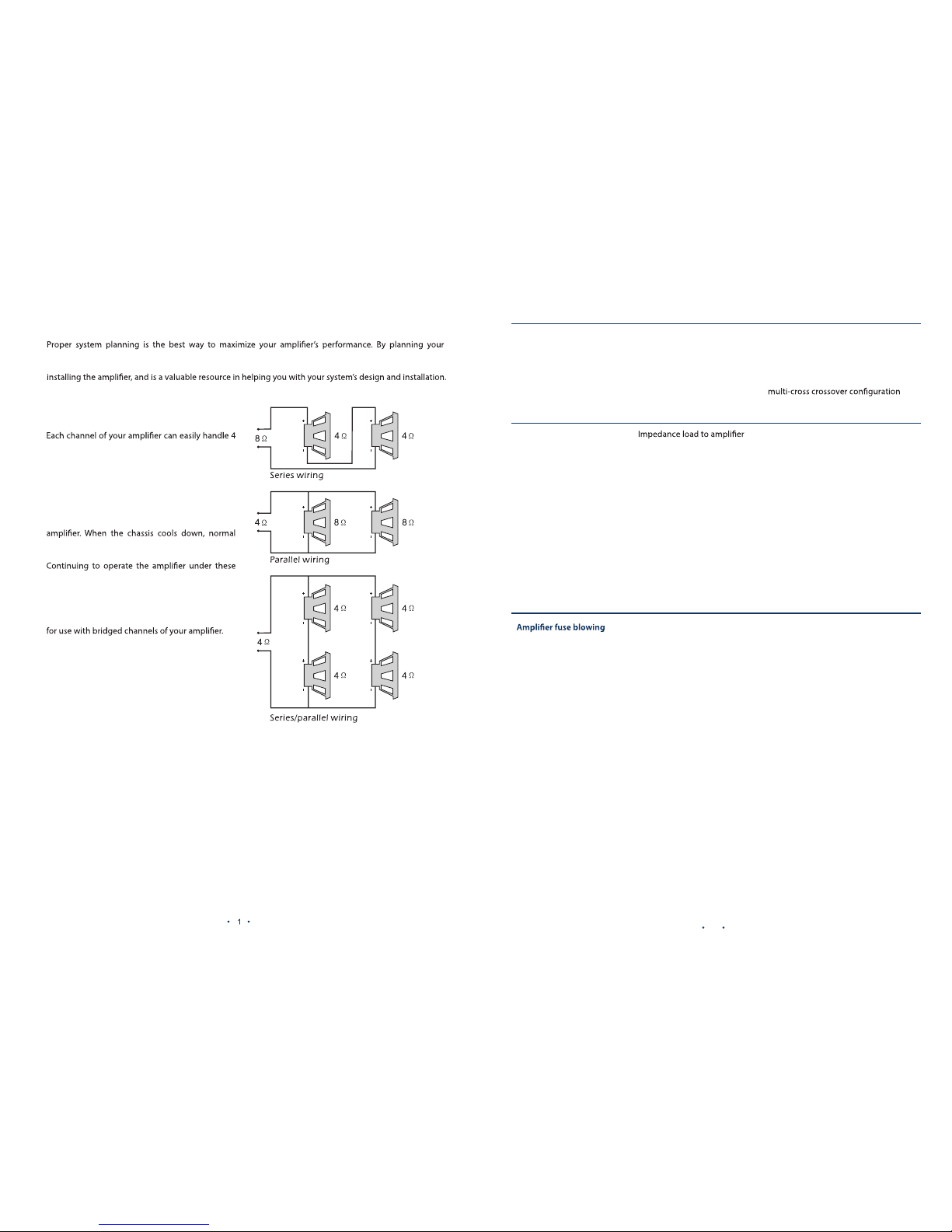
installation carefully, you can avoid situations where the performance and reliability of your system is
compromised. Our authorized dealer has been trained to maximize your system’s sound quality when
Ω speaker loads when used in Stereo Mode. When
a channel-pair is bridged, the recommended
minimum load impedance is 3Ω for subwoofer use,
and 4Ω for full range operation. Although
operation with lower impedances is not likely to
cause immediate damage to the internal circuitry,
the unit will most likely overheat, causing the
thermal protection circuitry to shut down the
operation will resume.
conditions is not recommended and will reduce its
life expectancy. Most speakers designed for car
audio operation are 4Ω impedance. Connecting
two such speakers in parallel will result in a 2Ω
nominal impedance, which is not recommended
Poor bass response Speakers wired wrong
polarity causing cancellation
at low frequencies
Check speaker polarity and repair as
needed
Crossover set incorrectly Reset crossover referring to the
section of this manual for detailed
instructions
Battery fuse blowing
too low
Check speaker impedance load. If below
2Ω stereo or 4Ω mono, rewire speakers
to achieve a higher impedance
Short in power wire or
incorrect power connections
Check power and ground connections
and repair as needed
Fuse used is smaller and
recommended
Replace with proper fuse size
Too much current being drawn Check speaker impedance load. If below
2Ω stereo or 4Ω mono, rewire speakers
to achieve a higher impedance and
replace with recommended fuse size
Short in power wire or incorrect
wire
Check power and ground connection and
repair as needed
Too much current being drawn
Check speaker impedance load. If below 2
Ω stereo or 4Ω mono, rewire speakers to
achieve a higher impedance and replace
with recommended fuse size
Check power and ground connections.
Repair as needed
Fuse used is smaller than
recommended
Replace with proper fuse size
Page 3

Trouble Shooting
CAR
AMP LIFIE R
tar t up
Conn ect t he am plifi er
s
outp ut to dri vers
ole osit ive ol e
he App ropri at se
Conn ected t o the
posi tive pole
Connection Diagram
efore beginni ng,
WARNING
Connect to the frame of
car for grounding
DO NOT connect the car battery’s negative poles to the positive poles.
Symptom Possible Caus e
Action to take
9
No output Low or no remote
turn-on input
Check remote turn-on voltage
needed
Fuse down
Check power wire integrity and
reverse polarity, repair as needed
and replace fuse
Power wires not connected Check power wire connections
and repair/replace as needed
Audio input not connected or
no output from source
Check input connections and signal
integrity repair/replace as needed
Speaker wires not connected
Check speaker wires and repair/
replace as needed
Speakers are blown
Check system with known working
speaker and repair/replace speakers
as needed
Thermal protection engages
temperature exceeds 90°C
Make sure there is proper ventilation
as needed
Loose or poor audio input
Check input connections and
repair/replace as needed
Distorted output
set too high, exceeding
maximum output capability
Reset gain. Refer to the turning section
of the manual for detailed instructions
too low
Check speaker impedance load. If below
2Ω stereo or 4Ω mono, rewire speakers
to achieve a higher impedance
Shorted speaker wires Check speaker wire connections and
repair/replace as needed
Speaker incorrectly
properly
Check speaker wiring and repair/replace
as needed. Refer to the installation
section of this manual for detailed
instructions
Speakers are blown Check system with known working
speaker and repair/replace as needed
Page 4

L R
BR I DG E
! " #$
%&'( ) *+, ) * -, , ) *. , ) *
!"!
"
System 1: 2- Channel Mode
System 2: Connection Subwoofer
AMP1501
Specifications
utp ut power 4Ω ( Watts)
utp ut power 2Ω ( Watts)
H
re uen cy resp onse ( 2d )
ign al to noise rati o
ens itivi ty
eco mmend ed fuse typ e
ime nsion s
563 W x 1 CH
330 W x 1CH (Τ
2%)
0.0 %
10H
300 Hz
0d
100 m 6
20A x 2
180 x 1
3 mm
Page 5

L R
BR I DG E
AMP7502
System 2: Bridge Connection Subwoofer
Specifications
utp ut power 4Ω ( Watts)
utp ut power 2Ω ( Watts)
rid ged out put power 4Ω (Watt s)
H
re uen cy resp onse ( 2d )
ign al to noise rati o
ens itivi ty
eco mmend ed fuse typ e
ime nsion s
330
W x 2 CH
325W x 2 CH
160W x 1CH
H %)
0.0 %
10H
4 Hz
0d
1 0m 6
30A x 1
220 x 1
3 mm
System 1: Connection Subwoofer
!
"
$%&'
(&'
' ) **
' + + * ,
$#( - .! ( - .(/ $010
23 4 +, 3
9
(
Page 6

C H3 C H4
BR I DG E
C H1 CH 2
! "#$%&' ( %& ! "#$%&' ( %&)( ( %&* ( %&
+ , -.+ , -.
System 1: 4-Channel Mode
System 2: Bridge Connection Subwoofer
Specifications
utp ut power 4Ω ( Watts)
utp ut power 2Ω ( Watts)
rid ged out put power 4Ω (Watt s)
H
re uen cy resp onse ( 2d )
ign al to noise rati o
ens itivi ty
eco mmend ed fuse typ e
ime nsion s
300W x 4 CH
150W x 4CH
1500W x 2CH
0.0 %
10H
4 Hz
0d
1 0m 6
30A x 2
300 x 1
3 mm
C H3 C H4
BR I DG E
C H1 CH 2
AMP1504
 Loading...