

Page 1
Signal Conditioner
Intelligent Frequency Converter
SGN-UM-00283-EN-03 (July 2015)
User Manual
Page 2

Signal Conditioner, Intelligent Frequency Converter
CONTENTS
Scope of This Manual . . . . . . . . . . . . . . . . . . . . . . . . . . . . . . . . . . . . . . . . . . . . . . . . . . . . . . . . . . . . . . . . . . . 3
Unpacking and Inspection . . . . . . . . . . . . . . . . . . . . . . . . . . . . . . . . . . . . . . . . . . . . . . . . . . . . . . . . . . . . . . . 3
Safety . . . . . . . . . . . . . . . . . . . . . . . . . . . . . . . . . . . . . . . . . . . . . . . . . . . . . . . . . . . . . . . . . . . . . . . . . . . . . 3
Terminology and Symbols . . . . . . . . . . . . . . . . . . . . . . . . . . . . . . . . . . . . . . . . . . . . . . . . . . . . . . . . . . . . . 3
Considerations . . . . . . . . . . . . . . . . . . . . . . . . . . . . . . . . . . . . . . . . . . . . . . . . . . . . . . . . . . . . . . . . . . . . 3
Electrical Symbols . . . . . . . . . . . . . . . . . . . . . . . . . . . . . . . . . . . . . . . . . . . . . . . . . . . . . . . . . . . . . . . . . . 3
Introduction. . . . . . . . . . . . . . . . . . . . . . . . . . . . . . . . . . . . . . . . . . . . . . . . . . . . . . . . . . . . . . . . . . . . . . . . . 4
Connection . . . . . . . . . . . . . . . . . . . . . . . . . . . . . . . . . . . . . . . . . . . . . . . . . . . . . . . . . . . . . . . . . . . . . . . . . 4
Loop Resistance . . . . . . . . . . . . . . . . . . . . . . . . . . . . . . . . . . . . . . . . . . . . . . . . . . . . . . . . . . . . . . . . . . . 5
Power Supply Calculations. . . . . . . . . . . . . . . . . . . . . . . . . . . . . . . . . . . . . . . . . . . . . . . . . . . . . . . . . . . . . 5
Calibration. . . . . . . . . . . . . . . . . . . . . . . . . . . . . . . . . . . . . . . . . . . . . . . . . . . . . . . . . . . . . . . . . . . . . . . . . . 6
Maintenance . . . . . . . . . . . . . . . . . . . . . . . . . . . . . . . . . . . . . . . . . . . . . . . . . . . . . . . . . . . . . . . . . . . . . . . . 6
Part Number Information . . . . . . . . . . . . . . . . . . . . . . . . . . . . . . . . . . . . . . . . . . . . . . . . . . . . . . . . . . . . . . . . 6
Troubleshooting Guide. . . . . . . . . . . . . . . . . . . . . . . . . . . . . . . . . . . . . . . . . . . . . . . . . . . . . . . . . . . . . . . . . . 6
Specications . . . . . . . . . . . . . . . . . . . . . . . . . . . . . . . . . . . . . . . . . . . . . . . . . . . . . . . . . . . . . . . . . . . . . . . . 7
Page ii July 2015
Page 3
Scope of This Manual
SCOPE OF THIS MANUAL
This manual is intended to help you get the Intelligent Frequency Converter up and running quickly.
MPORTANTI
Read this manual carefully before attempting any installation or operation. Keep the manual accessible for future reference.
UNPACKING AND INSPECTION
Upon opening the shipping container, visually inspect the product and applicable accessories for any physical damage such
as scratches, loose or broken parts, or any other sign of damage that may have occurred during shipment.
OTE:N If damage is found, request an inspection by the carrier’s agent within 48 hours of delivery and file a claim with the
carrier. A claim for equipment damage in transit is the sole responsibility of the purchaser.
SAFETY
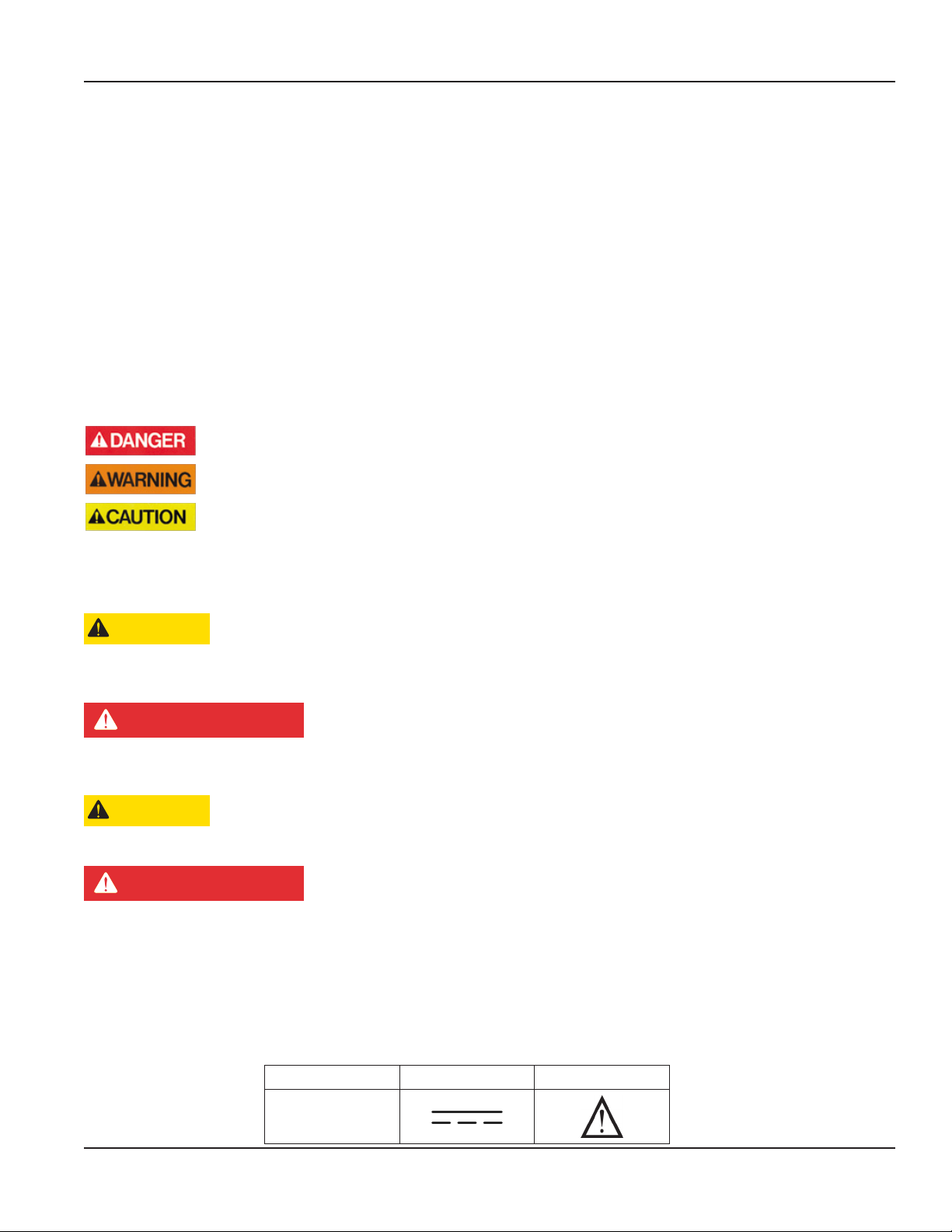
Terminology and Symbols
Indicates a hazardous situation, which, if not avoided, is estimated to be capable of causing death or
serious personal injury.
Indicates a hazardous situation, which, if not avoided, could result in severe personal injury or death.
Indicates a hazardous situation, which, if not avoided, is estimated to be capable of causing minor or
moderate personal injury or damage to property.
Considerations
The installation of the Intelligent Frequency Converter must comply with all applicable federal, state, and local rules,
regulations, and codes.
CAUTION
IF THE EQUIPMENT IS USED IN A MANNER NOT SPECIFIED BY THE MANUFACTURER, THE PROTECTION PROVIDED BY
THE EQUIPMENT MAY BE IMPAIRED.
AVERTISSMENT
DANS LE CAS D'UNE UTILISATION NON PRÉVUE PAR LE FABRICANT, LA PROTECTION FOURNIE PAR L'ÉQUIPEMENT PEUT
ÊTRE RÉDUITE.
CAUTION
FOR FIELD WIRING CONNECTIONS, WIRE MUST BE RATED AT 158° F (70° C) OR HIGHER.
AVERTISSMENT
POUR DES CÂBLAGES SUR LE TERRAIN, LES CÂBLES DOIVENT ÊTRE ÉVALUÉS À 70° C (158° F) MINIMUM.
MPORTANTI
Not following instructions properly may impair safety of equipment and/or personnel.
MPORTANTI
Must be operated by a class 2 power supply suitable for the location.
Electrical Symbols
Function Direct Current Caution
Symbol
Page 3 July 2015 SGN-UM-00283-EN-03
Page 4

Introduction
INTRODUCTION
The Intelligent Frequency Converter is a state-of-the-art digital signal processing device designed to provide exceptional
accuracy at an affordable price. Designed for use with turbine meters, the sensor measures and calculates the flow rate to
produce an analog current or voltage output representative of the meter’s flow rate.
The Intelligent Frequency Converter is offered in two versions:
• The F to I converter provides a 4…20 mA output in a two-wire, loop-powered setup.
• The F to V converter provides a 0…5V DC output.
CONNECTION
The 4…20 mA output can drive auxiliary devices such as displays, recorders and computers, provided that the voltage
supplied by the power supply is adequate. Devices must be wired in series with the F to I converter and power supply. The
voltage drop across the load and the 6V DC minimum needed to drive the F to I converter determines the minimum voltage
required from the power supply.
The F to I converter acts as a current controlling device keeping the current output the same even if the power supply voltage
fluctuates or the load resistance changes. The current varies only with respect to the flow rate from the turbine flow meter, as
long as the voltage drop across the F to I converter is at least 6V DC.
The load in the circuit generally has some electrical resistance, 100 ohms for this example. The 4…20 mA loop current will
produce a voltage drop across each load. The maximum voltage drop across a load exist when the loop current is 20 mA. The
power supply must provide enough voltage for the load plus the 6V DC minimum insertion loss of the F to I converter.
OTE:N See examples in Power Supply Calculations on page 5.
See the wiring diagrams in Figure 1 or Figure 2 for the appropriate wiring configuration for your application.
1 32
+
4…20 mA
Loop-Power
1 32
1 32
4…20 mA (+)
4…20 mA (-)
No Connection
4 5
Turbine
Pickup
B
A
Gnd.
0…5V DC
Output
10…26V DC
Input
1 32
10…26V DC Input
0…5V DC Output
4 5
Ground
4 5
Turbine
Pickup
B
A
4 5
Figure 1: F to I wiring diagram Figure 2: F to V wiring diagram
Page 4 July 2015SGN-UM-00283-EN-03
Page 5

Loop Resistance
Loop Load (Ohm's)
1400
1200
1000
800
600
400
200
Connection
Operate in the
Shaded Region
10 12 14 16 18 20 22 24
Supply Voltage (VDC)
Figure 3: Loop resistance chart
28 30
26
Power Supply Calculations
Example 1
F to I
Converter
Figure 4: Power supply calculation example 1
150
Ohms
4…20 mA
100
Ohms50Ohms
Known values are:
Total Load Resistance = 300 Ω
Power Supply = 24V DC
At 20 mA loop current, the voltage drop across the load is:
300 Ω x 20 mA = 6000 mV (6V)
Subtract 6V from the 24V source to determine that 18V are available to power the F to I converter. The 18V are within the
specified 10…30V range and is sufficient to power the F to I converter.
Example 2
24V DC
Power
Supply
Known values are:
Total Load Resistance = 1000 Ω
Power Supply = 24V DC
At 20 mA loop current, the voltage drop across the load is:
Subtract 20V from the 24V source to determine that 4V are available to power the F to I converter. The 4V are below the
specified 10…30V range and is not sufficient to power the F to I converter.
In this instance, either the supply voltage must be increased of the load resistance decreased.
F to I
Converter
Figure 5: Power supply calculation example 2
1000 Ω x 20 mA = 20,000 mV (20 Volts)
4…20 mA
1000
Ohms
24V DC
Power
Supply
Page 5 July 2015 SGN-UM-00283-EN-03
Page 6

Calibration
CALIBRATION
If your Intelligent Frequency Converter was purchased with a turbine meter, the two components ship from the factory
calibrated as a set. If the Intelligent Frequency Converter is a replacement, the turbine’s K-factor has changed, or the converter
is being used with another pulse-generating device, the Intelligent Frequency Converter can be calibrated by the factory, or
by using the B220-954 Intelligent Frequency Converter Programming kit. The programming kit is sold separately.
MAINTENANCE
1. Determine a schedule for maintenance checks based on the environment and frequency of use. Inspect the frequency
converter at least once a year.
2. Perform visual, electrical and mechanical checks on all components on a regular basis.
a. Visually check damage and discoloration of wires or other components caused by overheating, damaged or worn parts
or water or corrosion in the interior caused by a leak.
b. Make sure that all electrical connections are clean and tight, and that the device is operating correctly.
PART NUMBER INFORMATION
Description Part Number
Aluminum “Y” enclosure B220239
Pickup cable B222-120
Complete programming package B220-954
F to I device only B220803
F to V device only B220806
TROUBLESHOOTING GUIDE
Trouble Remedy
No current output
Analog output reads a constant
reading
Analog output is not stable
• Check polarity of the current loop connections for proper orientation.
• Make sure receiving device is configured to provide loop current.
• Make sure there is flow in the system.
• Verify that the rotor inside the turbine meter turns freely.
• External noise is being picked up by the sensor. Keep all AC wires separate from
DC wires.
• Check for radio antenna in close proximity. This usually indicates a weak signal.
Page 6 July 2015SGN-UM-00283-EN-03
Page 7

SPECIFICATIONS
Specications
Frequency to Current (F to I)
B220-873
Power
Inputs
Source Magnetic Pickup Magnetic Pickup
Frequency 0…3500 Hz 0…3500 Hz
Trigger Sensitivity 30 mV p-p 30 mV p-p
Frequency Measurement Accuracy ±1% ±1%
Analog Output
Type 4…20 mA current loop 0…5V DC
Resolution 1:4000 1:4000
Temperature Drift 50 ppm / ° C (maximum) 50 ppm / ° C (maximum)
Environmental
Ambient Temperature –22…158° F (–30…70° C) –22…158° F (–30…70° C)
Humidity 0…90% non-condensing 0…90% non-condensing
Altitude 2000 m 2000 m
Use Indoor/outdoor Indoor/outdoor
Enclosure
Agency Listings
Ordinary Location CAN/CSA-C22.2 No. 61010-1-12, UL Std. No. 61010-4 (3rd Edition)
Pollution Degree 2
Overvoltage Category I
Loop powered, 6V insertion loss
maximum 10… 30V DC supply range
Kilark aluminum capped elbow Y-3. Class I, Div. 1 & 2, Groups C & D; Class II, Div. 1 & 2,
Groups E, F and G; Class III
Frequency to Voltage (F to V)
B220-874
10…26V DC supply range
Page 7 July 2015 SGN-UM-00283-EN-03
Page 8

Signal Conditioner, Intelligent Frequency Converter
Control. Manage. Optimize.
Blancett is a registered trademark of Badger Meter, Inc. Other trademarks appearing in this document are the property of their respective entities. Due to continuous research,
product improvements and enhancements, Badger Meter reserves the right to change product or system specications without notice, except to the extent an outstanding
contractual obligation exists. © 2015 Badger Meter, Inc. All rights reserved.
www.badgermeter.com
The Americas | Badger Meter | 4545 West Brown Deer Rd | PO Box 245036 | Milwaukee, WI 53224-9536 | 800-876-3837 | 414-355-0400
México | Badger Meter de las Americas, S.A. de C.V. | Pedro Luis Ogazón N°32 | Esq. Angelina N°24 | Colonia Guadalupe Inn | CP 01050 | México, DF | México | +52-55-5662-0882
Europe, Middle East and Africa | Badger Meter Europa GmbH | Nurtinger Str 76 | 72639 Neuen | Germany | +49-7025-9208-0
Europe, Middle East Branch Oce | Badger Meter Europe | PO Box 341442 | Dubai Silicon Oasis, Head Quarter Building, Wing C, Oce #C209 | Dubai / UAE | +971-4-371 2503
Czech Republic | Badger Meter Czech Republic s.r.o. | Maříkova 2082/26 | 621 00 Brno, Czech Republic | +420-5-41420411
Slovakia | Badger Meter Slovakia s.r.o. | Racianska 109/B | 831 02 Bratislava, Slovakia | +421-2-44 63 83 01
Asia Pacic | Badger Meter | 80 Marine Parade Rd | 21-06 Parkway Parade | Singapore 449269 | +65-63464836
China | Badger Meter | 7-1202 | 99 Hangzhong Road | Minhang District | Shanghai | China 201101 | +86-21-5763 5412 Legacy Document Number: 02-SGN-UM-00118
 Loading...