

Page 1
Turbine Flow Meter
B1500
DESCRIPTION
Blancett B1500 turbine flow meters have exceptional mechanical
linearity, resulting in minimizing, or negating, temperature induced
viscosity influence. Meters come with national pipe thread (NPT)
or flange process fittings, sizes up to two inches and can be
ordered with a Blancett B3000 flow monitor for advanced
linearization and to accommodate the requirements of most
applications and flow ranges.
Features Benefits
Expanded
mechanical linearity
Helical rotor design
High-performance
ceramic ball bearings
6-bladed rotor
supports
Facility with NIST
traceable standards
OPERATING PRINCIPLE
As a fluid passes through the meter, the velocity of the fluid
provides rotational energy on the rotor blade assembly. The rotor
blades, passing through a magnetic field (produced by the pickoff),
generate pulses proportional to flow. Each pulse is transmitted to
the flow monitor, where the monitor calculates the flow relative to
received pulses and meter size.
APPLICATIONS
Blancett B1500 flow meters are the ideal solutions for standard
clean, filtered liquid flow applications in precision industrial
processes, found in the chemical/petrochemical, refining and
general industries.
Increased usable flow range with less
sensitivity to fluid temperature/viscosity
effects.
Exceptional speed-of-response, with
reduced pressure drop.
Ceramic bearings provide near-perfect
roundness, higher Rockwell hardness
and are lighter and more tolerant to
temperature than 440C stainless steel
bearings. They eliminate adhesive wear
and perform well in non-lubricating
liquids found in cryogenic fluids
and water.
Improved flow conditioning.
Third party audits to ensure calibration
uncertainty. Laboratory correlation to
verify that all calibrators produce the
same result.
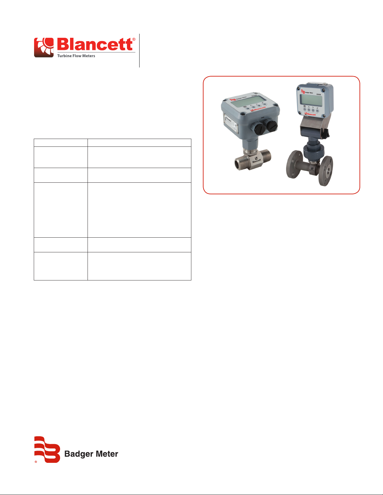
Shown with Blancett B3000
CONSTRUCTION
Blancett B1500 flow meters feature 316 stainless steel housings.
Wetted materials include axial helical rotors, made of 17-4 stainless
steel, that rotate on ceramic ball bearings. The supports and all
other materials are made from 300 series stainless steel.
METER INSTALLATION
Blancett B1500 flow meters mount directly in the piping and
can be installed in any position without affecting performance.
For optimal performance, recalibrate the meter if the mounting
orientation is changed from the original horizontal calibration.
To reduce flow turbulence, install a minimum of 10 diameters in
length of straight piping upstream and a minimum of five pipe
diameters downstream. If this cannot be accommodated due to
space limitations, pay careful attention to the location of valves
and bends. To compensate for piping bends, meters can be
calibrated in the same piping configuration. For best performance
and longevity, upstream filtration (10…75 micron, depending on
meter size), is helpful to prevent bearing contamination and to
avoid rotor blade damage.
CALIBRATION
Meters come with a best-in-class 10-point calibration, traceable to
NIST standards, using calibration solvent.
TRB-DS-01799-EN-02 (June 2016)
Product Data Sheet
Page 2
Optional System Conguration
Model
Blancett B1500 Turbine Flow Meter B150
Meter Size
1/4 in. (6.3 mm) Bore | 1/2 in. (12.7 mm) End Fitting 501
3/8 in. (9.5 mm) Bore | 1/2 in. (12.7 mm) End Fitting 502
End Fitting
OPTIONAL SYSTEM CONFIGURATION
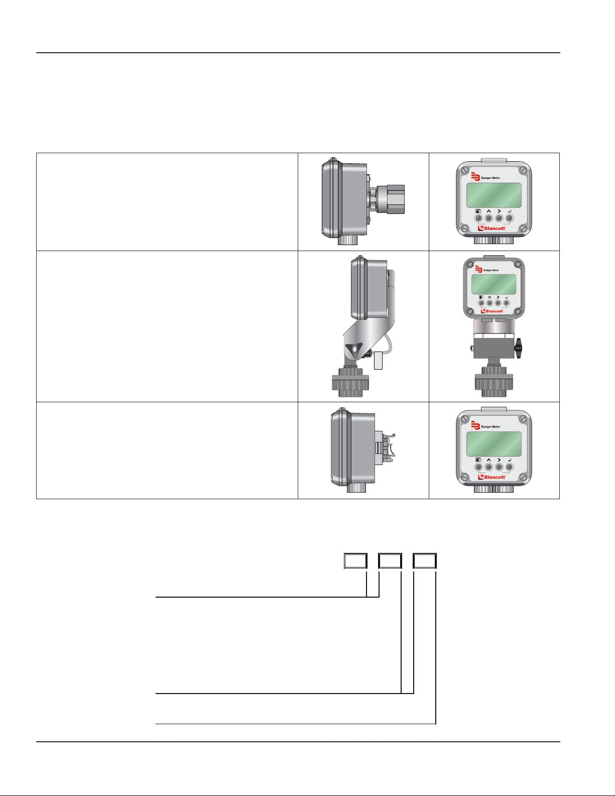
As an added benefit, B1500 flow meters that are coupled to B3000 flow monitors provide an economical, robust flow metering solution,
with multiple local read and system integration options. Flow rates and totals are presented simultaneously via a crisp dot-matrix LCD
display and/or transmitted to a user interface via Modbus RTU, a 4…20 mA analog output or totalizing pulse output. Basic, advanced and
solar-powered configurations provide users with flexibility to meet the needs of most applications. Product configurations can be mounted
in multiple ways, further expanding product flexibility to create a complete flow metering solution.
Meter Mount
• Monitor is assembled to the flow meter for a complete,
compact flow measurement system
• NEMA 4X (IP 66) rated enclosure
Swivel Mount
• Capable of adjustment pivot of 180 degrees for ease
of viewing
• NEMA 4X (IP 66) rated enclosure
• Remote Swivel mount is available, consult the factory
for details
• Offers additional protection from elements
Remote Mount
• Ideal when then monitor needs to be remotely mounted
• Suitable for high temperature, excessive noise or
inaccessible areas
• NEMA 4X (IP 66) rated enclosure
• Panel, DIN rail and pipe mounting hardware are included
• Cable lengths from 10…100 ft (3…30.5 m) are sold separately
For more information on the Blancett B3000 flow monitor, visit www.badgermeter.com.
B3000
TOTAL FLOW RESET
B3000
TOTAL FLOW RESET
B3000
TOTAL FLOW RESET
METER MODEL NUMBER
1/2 in. (12.7 mm) Bore | 1/2 in. (12.7 mm) End Fitting 503
5/8 in. (15.9 mm) End Fitting 625
3/4 in. (19.0 mm) End Fiting 750
1 in. (25.4 mm) End Fitting 110
1-1/4 in. (31.7 mm) End Fitting 125
1-1/2 in. (38.1 mm) End Fitting 115
2 in. (50.8 mm) End Fitting 120
National Pipe Thread NPT
150# ANSI Rasied Face Flange F15
Page 2 June 2016TRB-DS-01799-EN-02
- -
Page 3
SPECIFICATIONS
Accuracy ± 0.5% of reading with single K-factor; 0.25% with B3000 linearization
Performance
Materials of
Construction
Flow Ranges
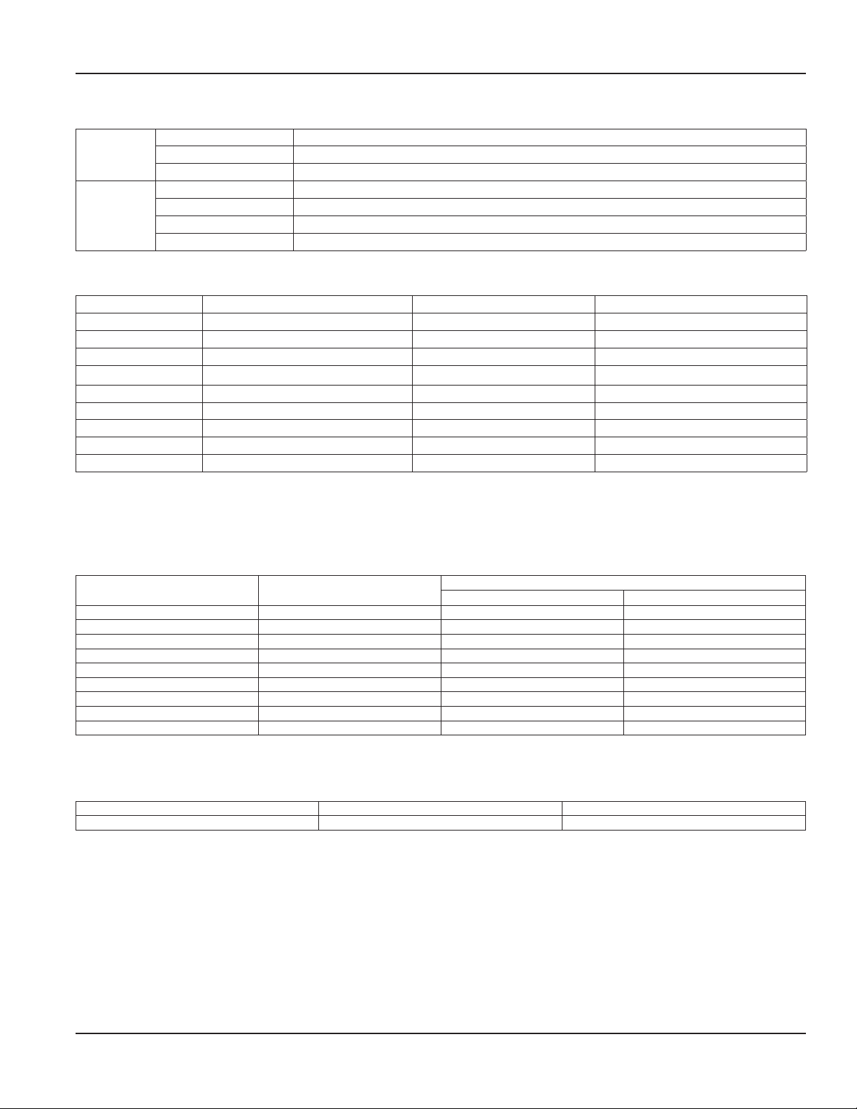
Part Number Flow Range ∆P at 10:1 * K-Factor**
B150-501-XXX 0.25…2.50 gpm (0.9…9.46 lpm) 3.5 PSID (0.25 kg/cm2) 28,800 pulses/US gal (7910 pulses/L)
B150-502-XXX 0.5…5.0 gpm (1.9…18.93 lpm) 4.5 PSID (0.32 kg/cm2) 14,400 pulses/US gal (3805 pulses/L)
B150-503-XXX 0.75…7.50 gpm (2.8…28.39 lpm) 6.0 PSID (0.42 kg/cm2) 9600 pulses/US gal (2536 pulses/L)
B150-625-XXX 1.25…12.50 gpm (4.7…47.32 lpm) 5.0 PSID (0.35 kg/cm2) 5760 pulses/US gal (1522pulses/L)
B150-750-XXX 2.5…25.0 gpm (9.5…94.63 lpm) 5.0 PSID (0.35 kg/cm2) 2800 pulses/US gal (761 pulses/L)
B150-110-XXX 5.0…50.0 gpm (18.9…189.27 lpm) 5.0 PSID (0.35 kg/cm2) 1440 pulses/US gal (380 pulses/L
B150-125-XXX 7.5…75.0 gpm (28.3…283.91 lpm) 5.5 PSID (0.39 kg/cm2) 960 pulses/US gal (254 pulses/L)
B150-115-XXX 12.5…125.0 gpm (47.3…473.18 lpm) 6.0 PSID (0.42 kg/cm2) 576 pulses/US gal (152 pulses/L)
B150-120-XXX 25…250.0 gpm (94.6…946.35 lpm) 6.5 PSID (0.46 kg/cm2) 288 pulses/US gal (76 pulses/L)
*Pressure drop is based on using MIL-PRF-17024E, Type II at 77° F (25° C), with a specic gravity of 0.77
**Actual K-factor varies from meter to meter and is listed on the calibration report
Repeatability ± 0.02% of reading
Response Time 2…3 ms (at 1.2 cSt)
Body 316 stainless steel
Shafts 316 stainless steel
Rotors 17-4 PH stainless steel
Bearing Ceramic
Specications
Pressure Ratings
NPT End Fittings
Part Number Nominal Pipe Size
B150-501-NPT 0.25 in. (6.35 mm) 5922 408
B150-502-NPT 0.37 in. (9.52 mm) 4700 324
B150-503-NPT 0.50 in. (12.70 mm) 4418 305
B150-625-NPT 0.75 in. (19.05 mm) 4136 285
B150-750-NPT 0.75 in. (19.05 mm) 4136 285
B150-110-NPT 1.00 in. (25.40 mm) 4042 278
B150-125-NPT 1.25 in. (31.75 mm) 4700 324
B150-115-NPT 1.50 in. (38.10 mm) 4230 291
B150-120-NPT 2.00 in. (50.80 mm) 3666 253
NOTES:
1. Pressure ratings listed are for temperatures up to 100° F (37.8° C).
2. Pressure rating is calculated with an allowable stress value of 20,000 psi (1378 bar) for 316 SS per pressure piping code ASME B31.3.
3. Chart is displaying safe working pressure, in accordance with power piping code ASME B31.1.
ANSI Flange PSIG Bar
150# 275 19
NOTES:
1. Specications from maximum non-shock allowable working pressure in psig at 100° F (37.8° C) or less.
2. Stainless steel 316A-181 material.
psig bar
Male
Page 3 June 2016 TRB-DS-01799-EN-02
Page 4
Turbine Flow Meter, B1500
A
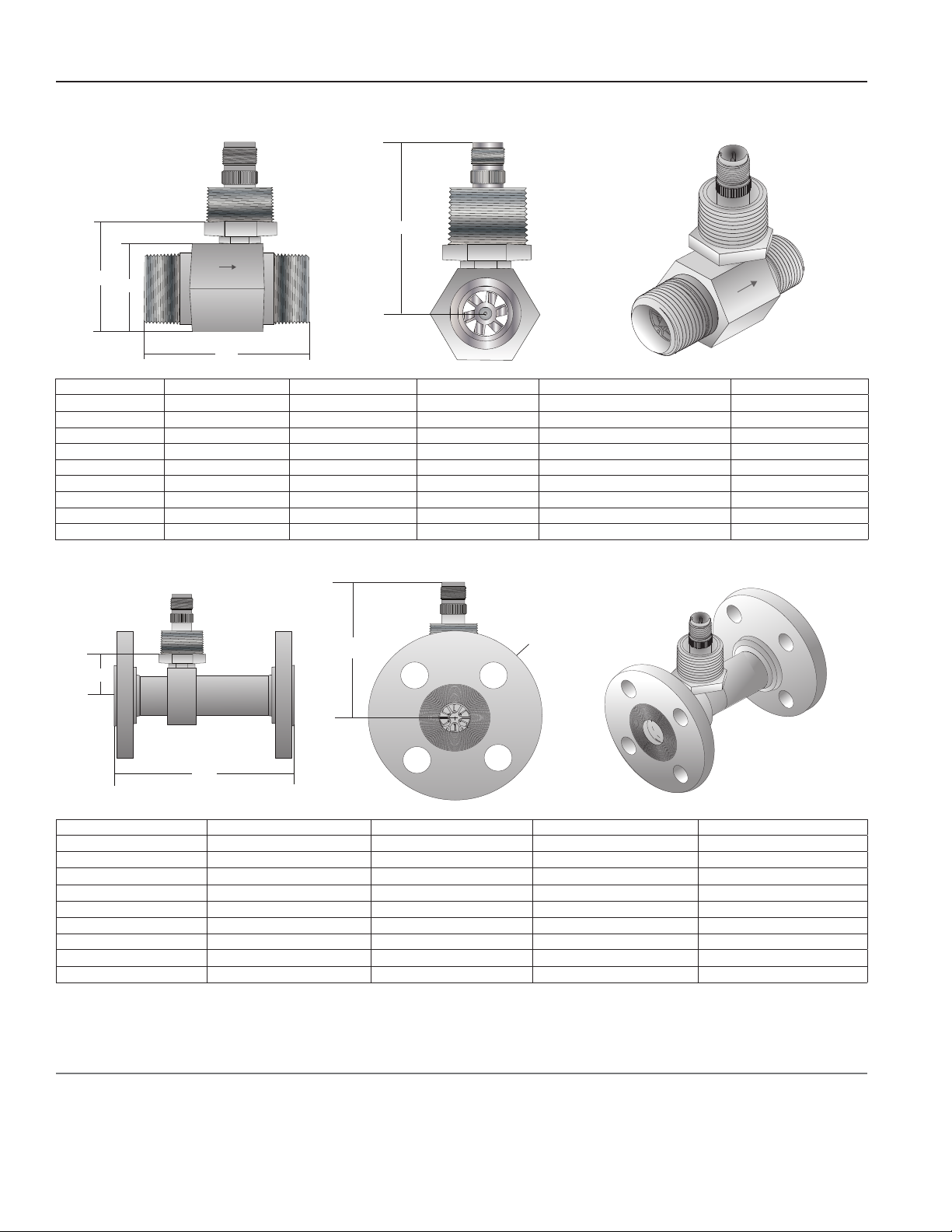
DIMENSIONS
NPT End Fitting
B
D
C
Part Number End Fitting A B C D
B150-501-NPT 0.50 in. (12.70 mm) 2.45 in. (62.23 mm) 2.70 in. (68.58 mm) 1.12 in. (28.45 mm) Square Body 1.62 in. (40.89 mm)
B150-502-NPT 0.50 in. (12.70 mm) 2.45 in. (62.23 mm) 2.70 in. (68.58 mm) 1.12 in. (28.45 mm) Square Body 1.62 in. (40.89 mm)
B150-503-NPT 0.50 in. (12.70 mm) 2.45 in. (62.23 mm) 2.80 in. (71.12 mm) 1.12 in. (28.45 mm) Square Body 1.62 in. (40.89 mm)
B150-625-NPT 0.625 in. (15.88 mm) 2.72 in. (69.08 mm) 2.80 in. (71.12 mm) 1.25 in. (31.75 mm) Square Body 1.75 in. (44.45 mm)
B150-750-NPT 0.75 in. (19.05 mm) 3.25 in. (82.55 mm) 2.90 in. (73.66 mm) 1.25 in. (31.75 mm) Square Body 1.75 in. (44.45 mm)
B150-110-NPT 1.00 in. (25.40 mm) 3.56 in. (90.42 mm) 3.00 in. (76.20 mm) 1.63 in. (41.40 mm) Hex Body 2.13 in. (54.10 mm)
B150-125-NPT 1.25 in. (31.75 mm) 4.06 in. (103.1 mm) 3.10 in. (78.74 mm) 1.88 in. (47.75 mm) Hex Body 2.38 in. (60.45 mm)
B150-115-NPT 1.50 in. (38.10 mm) 4.59 in. (116.6 mm) 3.30 in. (83.82 mm) 2.25 in. (57.15 mm) Hex Body 2.75 in. (69.85 mm)
B150-120-NPT 2.00 in. (50.80 mm) 6.06 in. (153.9 mm) 3.50 in. (88.90 mm) 2.75 in. (69.85 mm) Hex Body 2.75 in. (69.85 mm)
Flange End Fitting
B
D
A
Size A B C D
B150-501-F15 5.00 in. (127.0 mm) 2.52 in. (64.0 mm) 3.50 in. (88.9 mm) 1.03 in. (26.7 mm)
B150-502-F15 5.00 in. (127.0 mm) 2.52 in. (64.0 mm) 3.50 in. (88.9 mm) 1.06 in. (26.9 mm)
B150-503-F15 5.00 in. (127.0 mm) 2.62 in. (66.5 mm) 3.50 in. (88.9 mm) 1.12 in. (28.4 mm)
B150-625-F15 5.50 in. (139.7 mm) 2.62 in. (66.5 mm) 3.50 in. (88.9 mm) 1.19 in. (30.2 mm)
B150-750-F15 5.50 in. (139.7 mm) 2.72 in. (69.1 mm) 3.88 in. (99.6 mm) 1.26 in. (32.0 mm)
B150-110-F15 5.50 in. (139.7 mm) 2.82 in. (71.6 mm) 4.25 in. (107.9 mm) 1.37 in. (34.8 mm)
B150-125-F15 6.00 in. (152.4 mm) 2.92 in. (74.2 mm) 4.62 in. (117.3 mm) 1.49 in. (37.8 mm)
B150-115-F15 6.00 in. (152.4 mm) 3.12 in. (79.2 mm) 5.00 in. (127.8 mm) 1.61 in. (40.9 mm)
B150-120-F15 6.50 in. (165.1 mm) 3.32 in. (84.3 mm) 6.00 in. (152.4 mm) 1.84 in. (46.7 mm)
Ø C
Control. Manage. Optimize.
Blancett is a registered trademark of Badger Meter, Inc. Other trademarks appearing in this document are the property of their respective entities. Due to continuous research,
product improvements and enhancements, Badger Meter reserves the right to change product or system specications without notice, except to the extent an outstanding
contractual obligation exists. © 2016 Badger Meter, Inc. All rights reserved.
www.badgermeter.com
The Americas | Badger Meter | 4545 West Brown Deer Rd | PO Box 245036 | Milwaukee, WI 53224-9536 | 800-876-3837 | 414-355-0400
México | Badger Meter de las Americas, S.A. de C.V. | Pedro Luis Ogazón N°32 | Esq. Angelina N°24 | Colonia Guadalupe Inn | CP 01050 | México, DF | México | +52-55-5662-0882
Europe, Middle East and Africa | Badger Meter Europa GmbH | Nurtinger Str 76 | 72639 Neuen | Germany | +49-7025-9208-0
Europe, Middle East Branch Oce | Badger Meter Europe | PO Box 341442 | Dubai Silicon Oasis, Head Quarter Building, Wing C, Oce #C209 | Dubai / UAE | +971-4-371 2503
Czech Republic | Badger Meter Czech Republic s.r.o. | Maříkova 2082/26 | 621 00 Brno, Czech Republic | +420-5-41420411
Slovakia | Badger Meter Slovakia s.r.o. | Racianska 109/B | 831 02 Bratislava, Slovakia | +421-2-44 63 83 01
Asia Pacic | Badger Meter | 80 Marine Parade Rd | 21-06 Parkway Parade | Singapore 449269 | +65-63464836
China | Badger Meter | 7-1202 | 99 Hangzhong Road | Minhang District | Shanghai | China 201101 | +86-21-5763 5412
Switzerland | Badger Meter Swiss AG | Mittelholzerstrasse 8 | 3006 Bern | Switzerland | +41-31-932 01 11
 Loading...