

Page 1
Turbine Flow Meter
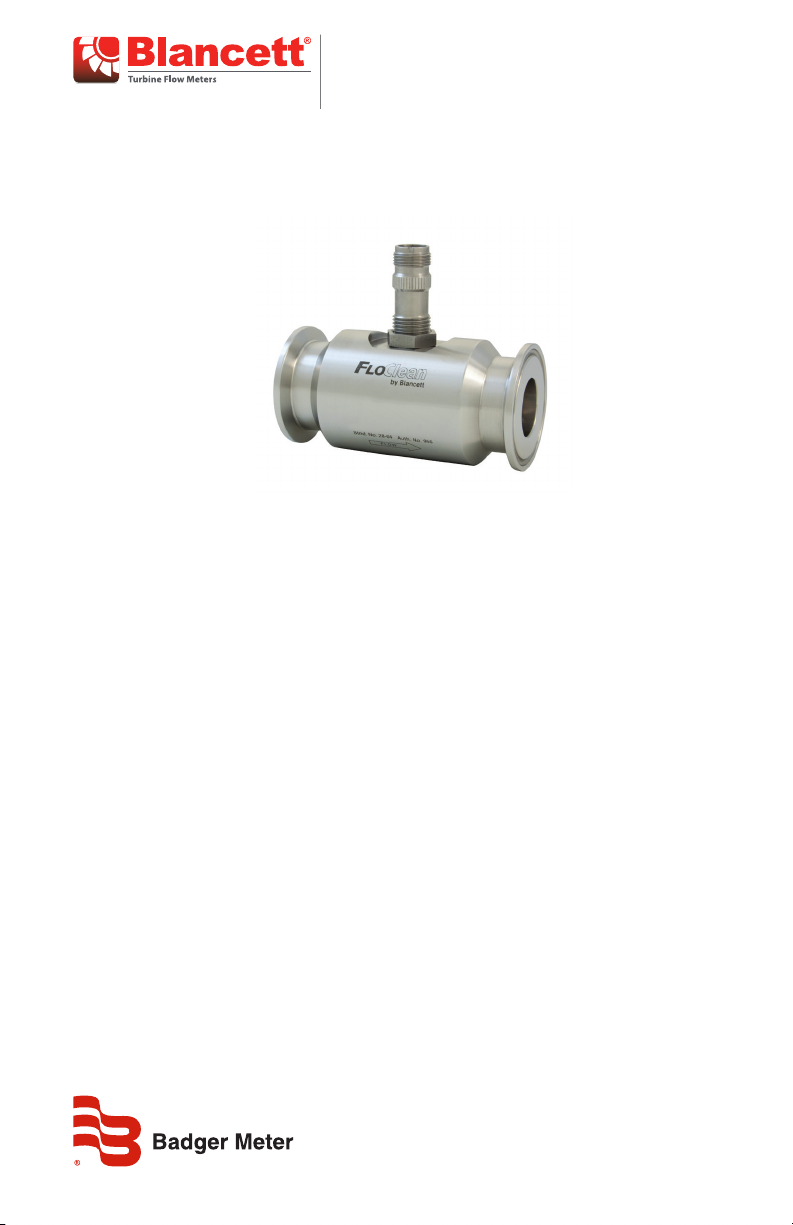
FloClean Repair Kit
TRB-UM-02123-EN-02 (November 2016)
User Manual
Page 2

Turbine Flow Meter, FloClean Repair Kit
CONTENTS
Safety Information. . . . . . . . . . . . . . . . . . . . . . . . . . . . . . . . . . . . . . . . . . . . . . . 3
Safety Symbol Explanations
Unpacking & Inspection . . . . . . . . . . . . . . . . . . . . . . . . . . . . . . . . . . . . . . . . . . . 3
Introduction. . . . . . . . . . . . . . . . . . . . . . . . . . . . . . . . . . . . . . . . . . . . . . . . . . . 3
Part Information . . . . . . . . . . . . . . . . . . . . . . . . . . . . . . . . . . . . . . . . . . . . . . . . 4
B16A Series (NDA)
B16C/B16N Series (COP/SOP)
B16D Series
Turbine Meter Removal . . . . . . . . . . . . . . . . . . . . . . . . . . . . . . . . . . . . . . . . . . . 5
Disassembly
Cleaning
Installation. . . . . . . . . . . . . . . . . . . . . . . . . . . . . . . . . . . . . . . . . . . . . . . . . . . . 7
. . . . . . . . . . . . . . . . . . . . . . . . . . . . . . . . . . . . . . . . . . . . . . . . . . 6
. . . . . . . . . . . . . . . . . . . . . . . . . . . . . . . . . . . . . . . . . . . . 4
. . . . . . . . . . . . . . . . . . . . . . . . . . . . . . . . . . . . . . . . . . . . . . . . 4
. . . . . . . . . . . . . . . . . . . . . . . . . . . . . . . . . . . . . . . . . . . . . . . 5
. . . . . . . . . . . . . . . . . . . . . . . . . . . . . . . . . . . . . 3
. . . . . . . . . . . . . . . . . . . . . . . . . . . . . . . . . . . . . 4
Page 2 November 2016TRB-UM-02123-EN-02
Page 3

Safety Information
SAFETY INFORMATION
The installation of the Blancett FloClean repair kits must comply with all applicable federal,
state, and local rules, regulations and codes.
Failures to read and follow these instructions can lead to misapplication or misuse of the
Blancett FloClean repair kits, resulting in personal injury and damage to equipment.
Safety Symbol Explanations
Indicates a hazardous situation, which, if not avoided, is estimated to
be capable of causing death or serious personal injury.
Indicates a hazardous situation, which, if not avoided, could result in
severe personal injury or death.
Indicates a hazardous situation, which, if not avoided, is estimated to
be capable of causing minor or moderate personal injury or damage
to property.
UNPACKING & INSPECTION
Upon opening the shipping container, visually inspect the product and applicable
accessories for any physical damage such as scratches, loose or broken parts, or any other
sign of damage that may have occurred during shipment.
OTE:N If damage is found, request an inspection by the carrier’s agent within 48 hours of
delivery and file a claim with the carrier. A claim for equipment damage in transit
is the sole responsibility of the purchaser.
INTRODUCTION
The FloClean turbine flow meter is designed with wear resistant moving parts to provide
trouble free operation and long service life. The kit allows easy field repair of a damaged
flow meter, rather than replacing the entire flow meter. Repair parts are constructed of
stainless steel alloy and tungsten carbide.
Each FloClean repair kit is factory calibrated for accuracy throughout the entire flow range.
Each kit is complete and includes a new K-factor, which is the calibrated number of pulses
generated by each gallon of liquid. This K-factor is used to recalibrate the monitor or other
electronics to provide accurate output data.
Page 3 November 2016 TRB-UM-02123-EN-02
Page 4

Part Information
PART INFORMATION
B16A Series (NDA)
Ferrule Size
0.984 in. B16A-003A-XXX B16C-K03A
0.984 in. B16A-005A-XXX B16C-K05A
0.984 in. B16A-007A-XXX B16C-K07A
1.984 in. B16A-105A-XXX B16C-K05A
1.984 in. B16A-107A-XXX B16C-K07A
1.984 in. B16A-108A-XXX B16C-K08A
1.984 in. B16A-110A-XXX B16C-K10A
1.984 in. B16A-115A-XXX B16C-K15A
3.047 in. B16A-220A-XXX B16C-K20A
Repair Kit Fits Meter Part
Number
Repair Kit Part Number
B16C/B16N Series (COP/SOP)
Ferrule Size Repair Kit Fits Meter Part Number
0.984 in. B16C-003A-XXX B16N-003A-XXX B16C-K03A
0.984 in. B16C-005A-XXX B16N-005A-XXX B16C-K05A
0.984 in. B16C-007A-XXX B16N-007A-XXX B16C-K07A
1.984 in. B16C-105A-XXX B16N-105A-XXX B16C-K05A
1.984 in. B16C-107A-XXX B16N-107A-XXX B16C-K07A
1.984 in. B16C-108A-XXX B16N-108A-XXX B16C-K08A
1.984 in. B16C-110A-XXX B16N-110A-XXX B16C-K10A
1.984 in. B16C-115A-XXX B16N-115A-XXX B16C-K15A
3.047 in. B16C-220A-XXX B16N-220A-XXX B16C-K20A
B16D Series
Repair Kit Part
Number
Ferrule Size
0.984 in. B16D-003A-XXX B16D-K03A
0.984 in. B16D-005A-XXX B16D-K05A
0.984 in. B16D-007A-XXX B16D-K07A
1.984 in. B16D-105A-XXX B16D-K05A
1.984 in. B16D-107A-XXX B16D-K07A
1.984 in. B16D-108A-XXX B16D-K08A
1.984 in. B16D-110A-XXX B16D-K10A
1.984 in. B16D-115A-XXX B16D-K15A
3.047 in. B16D-220A-XXX B16D-K20A
Repair Kit Fits Meter Part
Number
Page 4 November 2016TRB-UM-02123-EN-02
Repair Kit Part Number
Page 5

Turbine Meter Removal
TURBINE METER REMOVAL
HIGH-PRESSURE LEAKS ARE DANGEROUS AND CAUSE PERSONAL INJURY. MAKE SURE
THAT FLUID FLOW HAS BEEN SHUT OFF AND PRESSURE IN THE LINE RELEASED BEFORE
ATTEMPTING TO REMOVE THE METER.
METER BODY
JAM NUT
A
MAGNETIC PICK-UP
SLEEVE BEARING
ROTOR SUPPORT
A
REMOVE ROTOR
SECTION A-A
THRUST BALL EXTRACTION
HOLE
ROTATE ROTOR SUPPORT
THROUGH 180˚ TO
EXTRACT THRUST BALL
RELEASE JAM NUT AND
REMOVE MAGNETIC PICK-UP
RETAINING RING
THRUST BALL
ROTOR ASSEMBLY
REMOVE ROTOR SUPPORTS
DO NOT ROTATE DURING
EXTRACTION
REMOVE RETAINING RINGS
CLEAN AND INSPECT COMPONENT PARTS
PER 3A SANITARY STANDARDS; REVERSE
DISMANTLING PROCEDURE TO REASSEMBLE
Figure 1: Service procedure for B16C Series FloClean meters
Disassembly
See Figure 1 for relative positions of repair kit components.
1. Remove the magnetic pickup from the meter body to avoid damage during repair.
2. Remove the retaining ring from one end of the meter.
3. Remove the rotor support from the body. If the rotor support is jammed in the body,
use a pair of pliers or vice grips to break the rotor support free.
4. Remove the rotor assembly.
5. Remove the second retaining ring from the opposite side of the meter.
6. Remove the remaining rotor support from the body. If the rotor support is jammed in
the body, use a pair of pliers or vice grips to break the rotor support free.
7. Discard rotor, rotor supports, thrust balls and retaining rings.
Page 5 November 2016 TRB-UM-02123-EN-02
Page 6

Turbine Meter Removal
Cleaning
See Figure 1 on page 5 for pictorial view.
1. Remove the magnetic pickup from the meter body to avoid damage during procedure.
2. Remove the retaining ring from one end of the meter.
3. Keeping the meter upright (pickup port at the top), remove the rotor support from the
body taking care not to rotate it in the process. If the rotor support is jammed in the
body, use a pair of pliers or vice grips to break it free.
4. Hold the rotor support over a suitable container and rotate it 180°; the thrust ball will
drop out. Take care not to lose the ball.
5. Remove the rotor assembly.
6. Remove the second retaining ring from the opposite side of the meter.
7. Repeat steps 3 and 4 for the remaining rotor support.
8. Identify parts and ow direction to match with original meter body.
9. Clean the meter to meet your standards before installation.
Page 6 November 2016TRB-UM-02123-EN-02
Page 7

Installation
INSTALLATION
MPORTANTI
Before reassembly, note there are weep holes on each rotor support, these weep holes must be
facing down toward the bottom of the meter body when installed.
The meter must be reassembled with the arrows on the rotor pointed in the direction
of fluid flow. The magnetic pickup side of the body signifies the up position. This is the
position that the repair kit was calibrated, and this is the position to be used for meter
accuracy. Due to the polished surfaces, there are no arrows on the rotor support to
indicate which rotor support is to be placed upstream or downstream. Install the repair kit
as it was received in the box, using the arrow on the rotor to determine the placement of
the rotor support.
Each FloClean repair kit has been cleaned at the factory and handled with care. Clean the
meter to your standards before installation.
1. Drop a thrust ball into a rotor support through the hole provided in the side. Insert rotor
support into the meter body. Keep the thrust bearing hole pointed upwards to keep the
ball in place.
2. Secure a retaining ring in the groove provided. Be sure that the retaining ring is
completely installed in the groove.
3. Drop a thrust ball into second rotor support through the hole provided in the side.
Locate the rotor in the support sleeve bearing. Insert rotor support and rotor into the
meter body and the rst support sleeve bearing. Keep the thrust bearing hole pointed
upwards to keep the ball in place.
4. Secure the second retaining ring in the groove provided. Be sure that the retaining ring
is completely installed in the groove.
5. Check the meter by blowing air through the assembly. If the rotor does not turn freely,
the meter should be disassembled and checked for anything that would obstruct
movement of the rotor.
6. Install the magnetic pickup.
EXCESS AIR PRESSURE MAY DAMAGE THE ROTOR AND BEARINGS BY OVERSPINNING.
OTE:N The electronics will need recalibration after installation of the repair kit.
Page 7 November 2016 TRB-UM-02123-EN-02
Page 8

Turbine Flow Meter, FloClean Repair Kit
Control. Manage. Optimize.
BLANCETT is a registered trademark of Badger Meter, In. Other trademarks appearing in this document are the property of their respective entities. Due to
continuous research, product improvements and enhancements, Badger Meter reserves the right to change product or system specications without notice, except
to the extent an outstanding contractual obligation exists. © 2016 Badger Meter, Inc. All rights reserved.
www.badgermeter.com
The Americas | Badger Meter | 4545 West Brown Deer Rd | PO Box 245036 | Milwaukee, WI 53224-9536 | 800-876-3837 | 414-355-0400
México | Badger Meter de las Americas, S.A. de C.V. | Pedro Luis Ogazón N°32 | Esq. Angelina N°24 | Colonia Guadalupe Inn | CP 01050 | México, DF | México | +52-55-5662-0882
Europe, Middle East and Africa | Badger Meter Europa GmbH | Nurtinger Str 76 | 72639 Neuen | Germany | +49-7025-9208-0
Europe, Middle East Branch Oce | Badger Meter Europe | PO Box 341442 | Dubai Silicon Oasis, Head Quarter Building, Wing C, Oce #C209 | Dubai / UAE | +971-4-371 2503
Czech Republic | Badger Meter Czech Republic s.r.o. | Maříkova 2082/26 | 621 00 Brno, Czech Republic | +420-5-41420411
Slovakia | Badger Meter Slovakia s.r.o. | Racianska 109/B | 831 02 Bratislava, Slovakia | +421-2-44 63 83 01
Asia Pacic | Badger Meter | 80 Marine Parade Rd | 21-06 Parkway Parade | Singapore 449269 | +65-63464836
China | Badger Meter | 7-1202 | 99 Hangzhong Road | Minhang District | Shanghai | China 201101 | +86-21-5763 5412
Switzerland | Badger Meter Swiss AG | Mittelholzerstrasse 8 | 3006 Bern | Switzerland | +41-31-932 01 11 Legacy Document: B430-003
 Loading...