

Page 1

Turbine Flow Meter
B16D Series FloClean Sanitary
DESCRIPTION
The FloClean Sanitary turbine flow meter was developed for use
in the food, beverage and pharmaceutical industries. The 316L
stainless steel construction provides a durable and cost efficient
flow measurement system that offers excellent accuracy
and repeatability.
The FloClean uses the most up-to-date polishing technology
on all internal components and all materials comply with FDA
requirements. FloClean B16D Series meters have removable
thrust bearings for ease of cleaning and inspection, and meet
the requirements of 3-A Sanitary Standard number 28-04 for
use in clean-out-of-place (COP) and sanitize-out-of-place (SOP)
applications and carry the 3-A Sanitary symbol.
The FloClean output signal is a sine-wave that is proportional
to volumetric flow. With optional Blancett electronics, FloClean
provides local flow rate and volume totalization and interfaces with
most displays, PLCs and computers.
INSTALLATION
Install the flow meter with the flow arrow, which is etched on the
exterior of the meter body, pointing in the direction of fluid flow.
Install the meter horizontally with the magnetic pickup facing
upward. For optimum performance, the flow meter should be
installed with a minimum of 10 diameters upstream straight pipe
length and 5 diameters downstream straight pipe length.
REPAIR KITS
Factory calibrated replacement kits are available for field or factory
service. Both of the FloClean models are designed to allow for quick,
easy disassembly and replacement of internal components. The
repair kit contains two retaining rings, two rotor supports, one rotor
assembly and a K-factor tag.
TRB-DS-02185-EN-03 (September 2018)
Product Data Sheet
Page 2
Operating Principle
+1%
+%
AVG. K-FACTOR (K)
-%
STANDARD TURNDOWN APPROX. 10:1
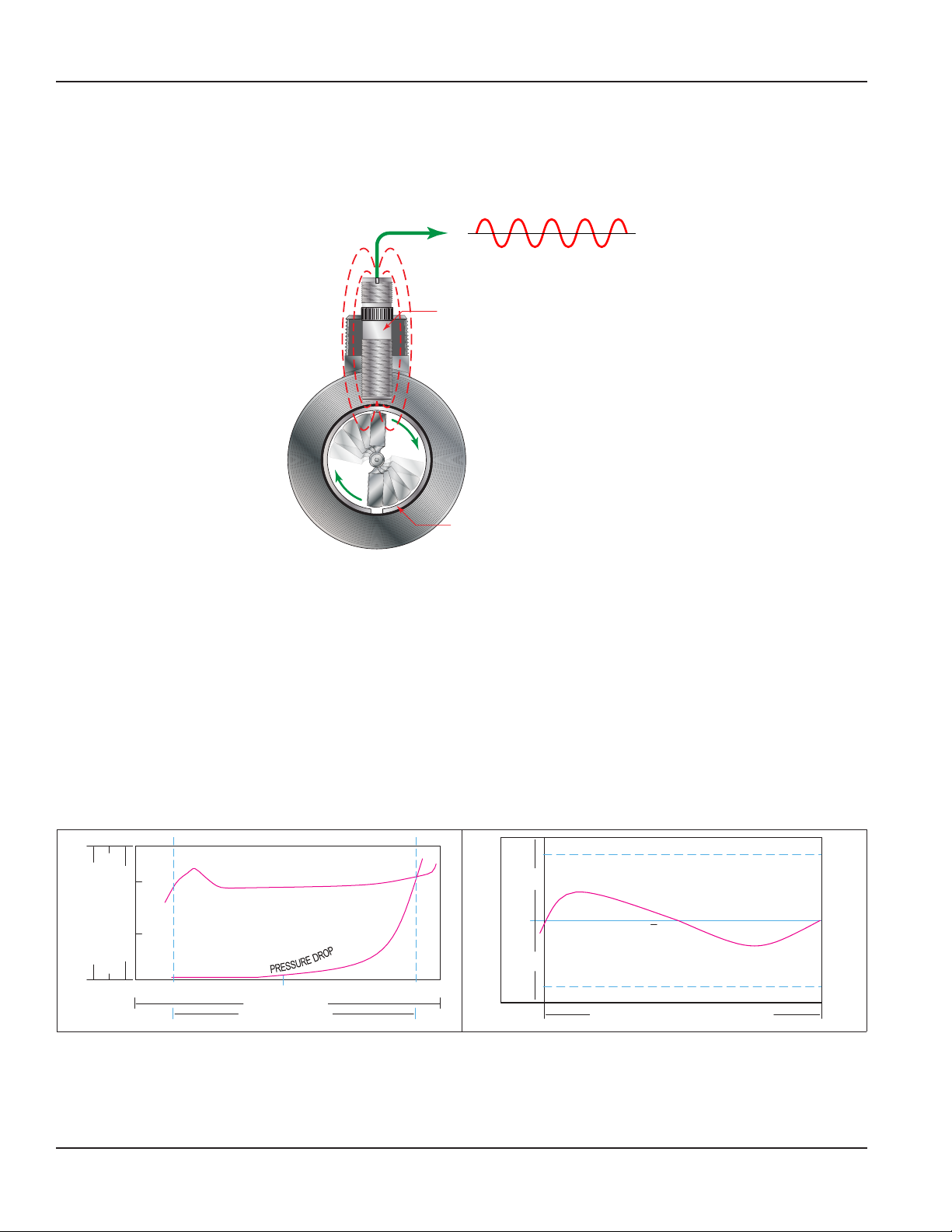
OPERATING PRINCIPLE
Fluid entering the meter first passes through an inlet flow straightener that reduces its turbulent flow pattern. Fluid then passes through
the turbine, causing the turbine to rotate at a speed proportional to fluid velocity. As each turbine blade passes through the magnetic field
generated by the meter’s magnetic pickup, an AC voltage pulse is generated. These pulses provide an output frequency that is proportional
to volumetric flow.
Output Signal
Magnetic
Pickup
Rotor
Figure 1: B142 turbine flow meter
KFACTOR
The K-factor represents the number of output pulses transmitted per gallon of fluid passing through the turbine meter. Each turbine has a
unique K-factor. However, turbine meters are not functionally consistent throughout the full flow range of the meter.
There are several forms of friction inherent in turbine meters that slow down the rotational movement of the turbine rotor. These frictional
forces include: magnetic drag, created by electromagnetic force of pickup transducers; mechanical drag, due to bearing friction; and viscous
drag, produced by flowing fluid.
See charts below.
As flow increases, the frictional forces are minimized and the free-wheeling motion of the turbine rotor becomes more linear (proportional
to flow). The K-factor becomes relatively constant and linear throughout the balance of the linear flow range. This is approximately a 10:1
turndown ratio from the maximum flow rate down to the minimum flow rate.
Typical K-factor Curve (Pulse per US Gallon)
100%
RATE
(CYCLES/SEC)
FLOW
AT
(CYCLES/GALLON)
LUE
A
50%
V
FREQUENCY
CTOR
A
OF
%
K-F
OUTPUT
0% 10%
K-FACTOR (PULSES/GALLON)
50%
FULL FLOW RANGE
LINEAR FLOW RANGE
100%
LINEARITY (DESIGN DEVIATION)
-1%
K
-
F
A
C
T
O
R
(
P
S
U
L
)
N
O
L
L
A
G
/
E
TRB-DS-02185-EN-03Page 2 September 2018
Page 3

SPECIFICATIONS
C
A
B
Body 316L stainless steel
Rotor Nickel plated CD4MCU stainless steel
Materials of Construction
Operating Temperature –150…300° F (–100…149° C)
Pressure Rating 1,000 psi (Rating based on tri-clamp sanitary connection)
End Connections Sanitary clamp end
Turndown Ratio —
Accuracy ±1.0% of reading
Repeatability ±0.1%
Calibration Water (NIST traceable calibration)
Mag Pickup NEMA 6; –150…300° F (–100…149° C)
Certifications
Bearings Standard-nickle bindery tungsten carbide
Rotor Shaft Nickel bindery tungsten carbide
Rotor Support —
Specications
DIMENSIONS
Part No. Part Number Code
A
End to End
003
B16D-0XXA-XXX
005
3.00 in. (76.2 mm) 1.46 in. (37.1 mm) 0.984 in. (25.0 mm)
007
105
B16D-1XXA-XXX
107
108
4.00 in. (101.6 mm) 2.00 in. (50.8 mm) 1.984 in. (50.4 mm)
110
B16D-1XXA-XXX ¹
B16D-2XXA-XXX
115
220
6.25 in. (158.8 mm) 2.33 in. (59.2 mm) 1.984 in. (50.4 mm)
6.50 in. (165.1 mm) 3.20 in. (81.3 mm) 3.047 in. (77.4 mm)
B
Diameter
C
Ferrule Size
TRB-DS-02185-EN-03 Page 3 September 2018
Page 4

Part Number Information
PART NUMBER INFORMATION
Part
Number
Code
003
005
007
105
107
108
110
115
220
Bore Size
3/8 in.
(9.53 mm)
1/2 in.
(12.7 mm)
3/4 in.
(19.05 mm)
1/2 in.
(12.7 mm)
3/4 in.
(19.05 mm)
7/8 in .
(22.23 mm)
1 in.
(25.4 mm)
1-1/2 in.
(38.1 mm)
2 in.
(50.8 mm)
End
Connections
0.984 in.
(25.0 mm)
0.984 in.
(25.0 mm)
0.984 in.
(25.0 mm)
1.984 in.
(50.4 mm)
1.984 in.
(50.4 mm)
1.984 in.
(50.4 mm)
1.984 in.
(50.4 mm)
1.984 in.
(50.4 mm)
3.047 in.
(77.4 mm)
Max
PSI
1000
1000
1000
1000
1000
1000
1000
1000
1000
gpm (lpm) bpd m/d
0.60…3.00
(2.27…11.36)
0.75…7.50
(2.84…28.39)
2.00…15.00
(7.57…56.78)
0.75…7.50
(2.84…28.39)
2.00…15.00
(7.57…56.78)
3.00…30.00
(11.36…113.56)
5.00…50.00
(18.93…189.27)
15.00…180.00
(56.78…681.37)
40.00…400.00
(151.42…1514.16)
Flow Rate
Strainer
Mesh
20.57…102.86 3.27…16.35 — 20,000 —
21.71…257.14 4.09…40.88 — 13,000 —
68.57…514.29 10.90…81.76 — 2750 —
21.71…257.14 4.09…40.88 — 13,000 —
68.57…514.29 10.90…81.76 — 2750 —
102.86…1028.57 16.35…163.53 — 2686 —
171.43…1714.29 27.25…272.55 — 870 —
514.29…6171.43 81.76…981.18 — 330 —
1371.43…13714.29 218.04…2180.40 — 52 —
Approx.
K-Factor
Pulse/US
Gal
Weight
Meter
(lb)
Ferrule
(mm)
0.984
(24.99)
0.984
(24.99)
0.984
(24.99)
1.984
(50.39)
1.984
(50.39)
1.984
(50.39)
1.984
(50.39)
1.984
(50.39)
3.047
(77.39)
Repair Kits
Bore Size Ferrule Size Repair Kit Fits Meter Part Number Part Number Code Repair Kit Part Number
3/8 in. (9.53 mm) 0.984 in. (24.99 mm) B16D-003A-XXX 003 B16D-K03A
1/2 in. (12.7 mm) 0.984 in. (24.99 mm) B16D-005A-XXX 005 B16D-K05A
3/4 in. (19.05 mm) 0.984 in. (24.99 mm) B16D-007A-XXX 007 B16D-K07A
1/2 in. (12.7 mm) 1.984 in. (50.39 mm) B16D-105A-XXX 105 B16D-K05A
3/4 in. (19.05 mm) 1.984 in. (50.39 mm) B16D-107A-XXX 107 B16D-K07A
7/8 in. (22.23 mm) 1.984 in. (50.39 mm) B16D-108A-XXX 108 B16D-K08A
1 in. (25.4 mm) 1.984 in. (50.39 mm) B16D-110A-XXX 110 B16D-K10A
1-1/2 in. (38.1 mm) 1.984 in. (50.39 mm) B16D-115A-XXX 115 B16D-K15A
2 in. (50.8 mm) 3.047 in. (77.39 mm) B16D-220A-XXX 220 B16D-K20A
Size
in.
End to
End
Length
in. (mm)
3.00
(76.2)
3.00
(76.2)
3.00
(76.2)
4.00
(101.60)
4.00
(101.60)
4.00
(101.60)
4.00
(101.60)
6.25
(158.8)
6.50
(165.1)
TRB-DS-02185-EN-03Page 4 September 2018
Page 5

PART NUMBERING CONSTRUCTION
1
M a gn etic | Standard
1
M agnetic w ith Pre-Am plifier | Standard
1
M agnetic w ith F/I Converter (Active 4…20 m A O utput)
1
M a gn etic | High Temperature (-450…450° F/-268…232° C)
1
M agnetic w ith F/V C onverter (Ac tive 0…5V D C O utput)
1
For Indoor Use Only
Part Numbering Construction
Blancett Turbine Flow Meters
B16D
-
A
FloClean: COP/SOP 3-A Compliant
FERRULE & METER SIZE
Ferrule: 0.984 in. | 3/4 in. Clamp x 3/8 in. Bore 003
Ferrule: 0.984 in. | 3/4 in. Clamp x 1/2 in. Bore 005
Ferrule: 0.984 in. | 3/4 in. Clamp x 3/4 in. Bore 007
Ferrule: 1.984 in. | 1-1/2 in. Clamp x 1/2 in. Bore 105
Ferrule: 1.984 in. | 1-1/2 in. Clamp x 3/4 in. Bore 107
Ferrule: 1.984 in. | 1-1/2 in. Clamp x 7/8 in. Bore 108
Ferrule: 1.984 in. | 1-1/2 in. Clamp x 1 in. Bore 110
Ferrule: 1.984 in. | 1-1/2 in. Clamp x 1-1/2 in. Bore 115
Ferrule: 3.047 in. | 2-1/2 in. Clamp x 2 in. Bore 220
BEARING
Nickel Bindery; Tungsten Carbide A
PICKUP
M a gn etic | NEMA 6 0
M agnetic w ith Pre-Am plifier | NEMA 6 1
-
2
3
4
6
M agnetic w ith Pre-Am plifier | NEMA 6 (Less Zenor) 7
8
No Pickup 9
METER BODY HUB
W ith H u b | 1/2 in. Hub for Ferrule Size 0.984; 1 in. Hub for 1.984 in. and 3.047 in A
No Hub B
CALIBRATION
5-Point | Standard A
10-Point B
20-Point C
Example Part Num ber: B16D -110A-2AA
TRB-DS-02185-EN-03 Page 5 September 2018
Page 6

Turbine Flow Meter, B16D Series FloClean Sanitary
INTENTIONAL BLANK PAGE
Page 6 September 2018TRB-DS-02185-EN-03
Page 7

INTENTIONAL BLANK PAGE
Product Data Sheet
Page 7 September 2018 TRB-DS-02185-EN-03
Page 8

Turbine Flow Meter, B16D Series FloClean Sanitary
Control. Manage. Optimize.
Blancett is a registered trademark of Badger Meter, Inc. Other trademarks appearing in this document are the property of their respective entities. Due to continuous research,
product improvements and enhancements, Badger Meter reserves the right to change product or system specications without notice, except to the extent an outstanding
contractual obligation exists. © 2018 Badger Meter, Inc. All rights reserved.
www.badgermeter.com
The Americas | Badger Meter | 4545 West Brown Deer Rd | PO Box 245036 | Milwaukee, WI 53224-9536 | 800-876-3837 | 414-355-0400
México | Badger Meter de las Americas, S.A. de C.V. | Pedro Luis Ogazón N°32 | Esq. Angelina N°24 | Colonia Guadalupe Inn | CP 01050 | México, DF | México | +52-55-5662-0882
Europe, Eastern Europe Branch Oce (for Poland, Latvia, Lithuania, Estonia, Ukraine, Belarus) | Badger Meter Europe | ul. Korfantego 6 | 44-193 Knurów | Poland | +48-32-236-8787
Europe, Middle East and Africa | Badger Meter Europa GmbH | Nurtinger Str 76 | 72639 Neuen | Germany | +49-7025-9208-0
Europe, Middle East Branch Oce | Badger Meter Europe | PO Box 341442 | Dubai Silicon Oasis, Head Quarter Building, Wing C, Oce #C209 | Dubai / UAE | +971-4-371 2503
Slovakia | Badger Meter Slovakia s.r.o. | Racianska 109/B | 831 02 Bratislava, Slovakia | +421-2-44 63 83 01
Asia Pacic | Badger Meter | 80 Marine Parade Rd | 21-06 Parkway Parade | Singapore 449269 | +65-63464836
Switzerland | Badger Meter Swiss AG | Mittelholzerstrasse 8 | 3006 Bern | Switzerland | +41-31-932 01 11 Legacy Document Number: Form No. 1300
 Loading...