

Page 1
ILLUSTRATED PARTS LIST
POTATO and
VEGETABLE
PEELERS
MODELS
S-15,XC-15,
XC-30,XC-60
(letter '"T" suffix after model number indicates peeler
is equipped with automatic timer).
LIMITED WARRANTY
Your new Blakeslee machine is warranted for one year from dale of installation shown above* against defective materials
and workmanship. If any defects are found within the above period, pans and authorized service-involved with their
replacement will be furnished free of charge. All labor to be performed during regular working hours. Overtime premium
will be charged to the customer. All warranty pans are shipped by surface transportation. If other means of transportation
is requested, the customer is required to pay the premium charge. This warranty does not apply to damages resulting from
errors in installation on the pan of other contractors, nor does it apply to machines which have been subject to accident,
alteration, misuse or abuse. It is understood that Blakeslee's warranty obligation with respect to machines located outside
of the United States or located in the state of ALASKA is limited to the furnishing of replacement pans only. In the state
of HAWAII. repair labor is provided free of charge; travel time and expenses paid by the customer. On .the Island of
Oahu, repair labor, travel time and expenses are provided free of charge. This is the entire and only warranty of G. S.
Blakeslee & Co. We neither assume nor authorize anyone else 10 assume for us any other obligation or liability in
connection with Blakeslee machines.
Blakeslee
* In no case can this warranty exceed eighteen (18) months from due of shipment from our plant at Cicero, Illinois.
BLAKESLEE
1844 S. LARAMIE AVE., CICERO, ILLINOIS 60650
Page 2
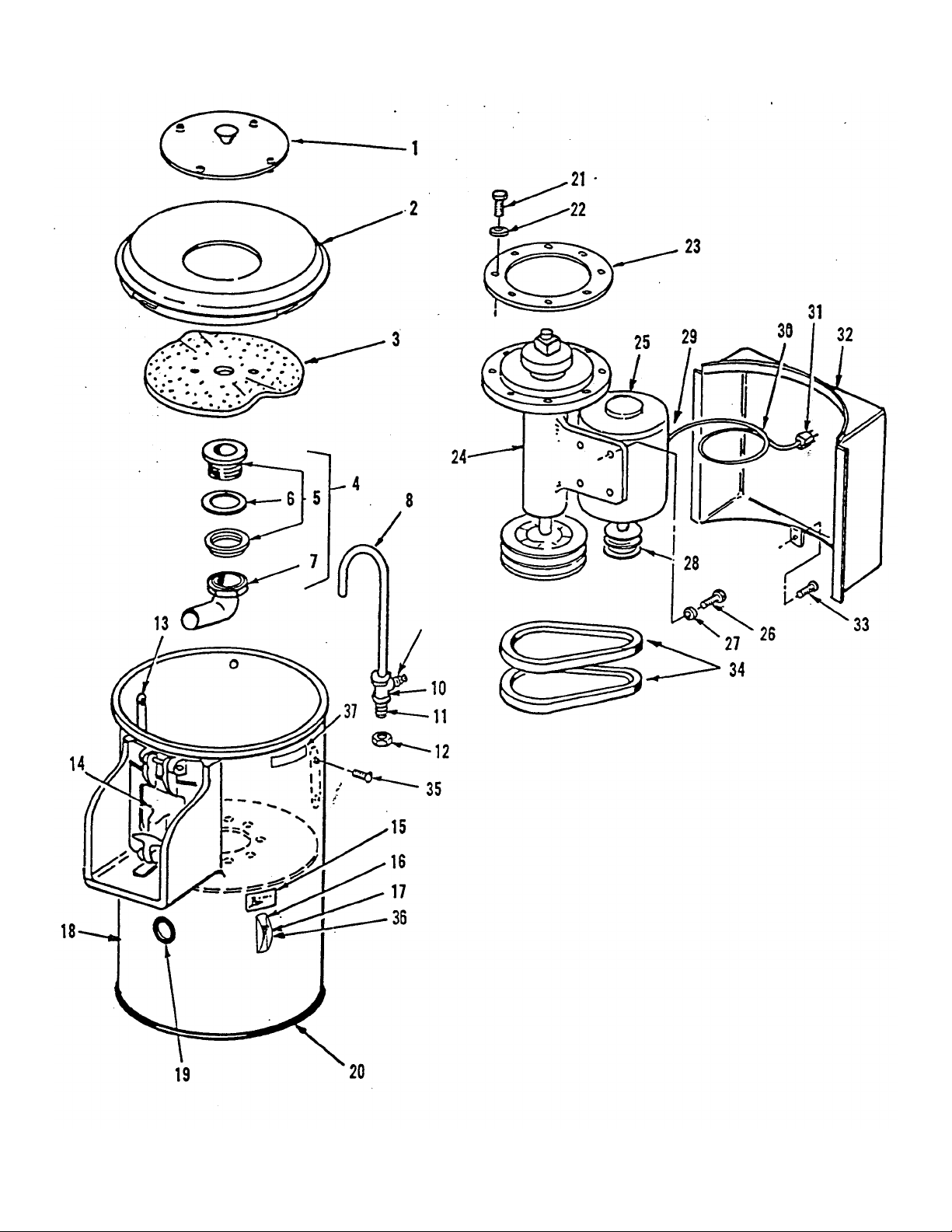
FIGURE 1 MODEL S-15
PEELER
2
Page 3

MODEL S-15 PEELER
No.
Item
No.
1 P2-5100 SPLASH COVER, Aluminum 1
2 P2-5163 HOPPER, Plastic 1
3 P4-5270 PEEL DISC 1
4 P2-5144 DRAIN ASSE MBLY (Consists of items 5, 6 & 7) 1
5 Pl-5291 DRAIN CUP w/ Flanged Locknut 1
6 P1-5292 GASKET 1
7 P1-5295 WASTE TUBE w/ Locknut and Rubber Washer 1
8 P1-5066 SPRAY PIPE 1
9 P1-17238 NIPPLE, Dixon Style 3500 1
10 P1-17236 TEE, 1/4 x 1/4 x 3/8" Female 1
11 P1-5210 STUD, 1/2 x 3" 1
12 WO-14192 LOCKNUT. 1/2 -13 Hex Jam Nut Cadm. Plated. 1
13 P1-5272 LOBE, Peeler 2
14 P4-5258 DOOR ASSEMBLY (See Fig. 3 for Detail Parts) 1
15 P1-5052 PLATE, Data 1
16 P1-5096 PLATE, Switch Cover 1
17 M1-15260 SWITCH, Toggle, 1 PH., Flush 1
17 P1-17203 SWITCH, Toggle, 3 PH., Flush 1
18 P4-5212 HOUSING, Upper w/ Chute Casting 1
19 P1-17246 RUBBER GROMMET 1
20 P1-17247 GASKET, Channel 1
21 W1-8148 CAPSCREW, 3/8 x 3/4" lg., S/S 8
22 W1-5567 WASHER, Plain 3/8" Cad. Pit 8
23 P2-5040 GASKET 1
24 P4-5219 BEARING COLUMN ASSY., Complete
25 P1-5280 MOTOR, 1/3 H.P., 1 PH. 115/230V 1
25 P1-5281 MOTOR, 1/3 H.P., 3 PH, 220V 1
26 W1-7111 CAPSCREW, 5/16 x 3/4" lg. Hex Hd. 4
27 P1-17235 LOCKWASHER, 5/16" 4
28 P1-5111 SHEAVE (2 Grooves) 1
29 M1-15388 CONNECTOR. 3/8"-90° (Not Illus.) 1
30 P1-17214 CORD, No. 14 AWG, 3 Wire Cond., 1 PH. 6ft
30 M1-15369 CORD, No. 14 AWG, 4 Wire Cond., 3 PH. 6ft
31 P1-17212 PLUG, Use with 3 Wire Cord, 120V, 1 PH., 15 Amp. 1
31A M1-15374 PLUG, Use with 3 Wire Cord, 250V, 1 PH., 15 Amp. 1
31B PO-17213 PLUG, Use with 4 Wire Cord, 208/240V. 60C, 3 PH., 20 Amp. 1
31C PO-95603 PLUG, Use with 4 Wire Cord, 480V, 60C, 3 PH., 20 Amp. 1
32 P4-5207 HOUSING, Motor Cover 1
33 W1-5987 SCREW, 10-24 x 1/2" Pan Hd. 1
34 P1-15211 V.BELT, 31" lg. 2
35 W1-10307 SCREW, 10/32 x 3/8" lg., Rd. Hd. Mach. 4
36 M1-95654 SWITCH GUARD 1
37 P1-95647 CAUTION LABEL 1
Part
No.
Description
(See Fig. 4 for detail parts) 1
Reqd.
3
Page 4
4
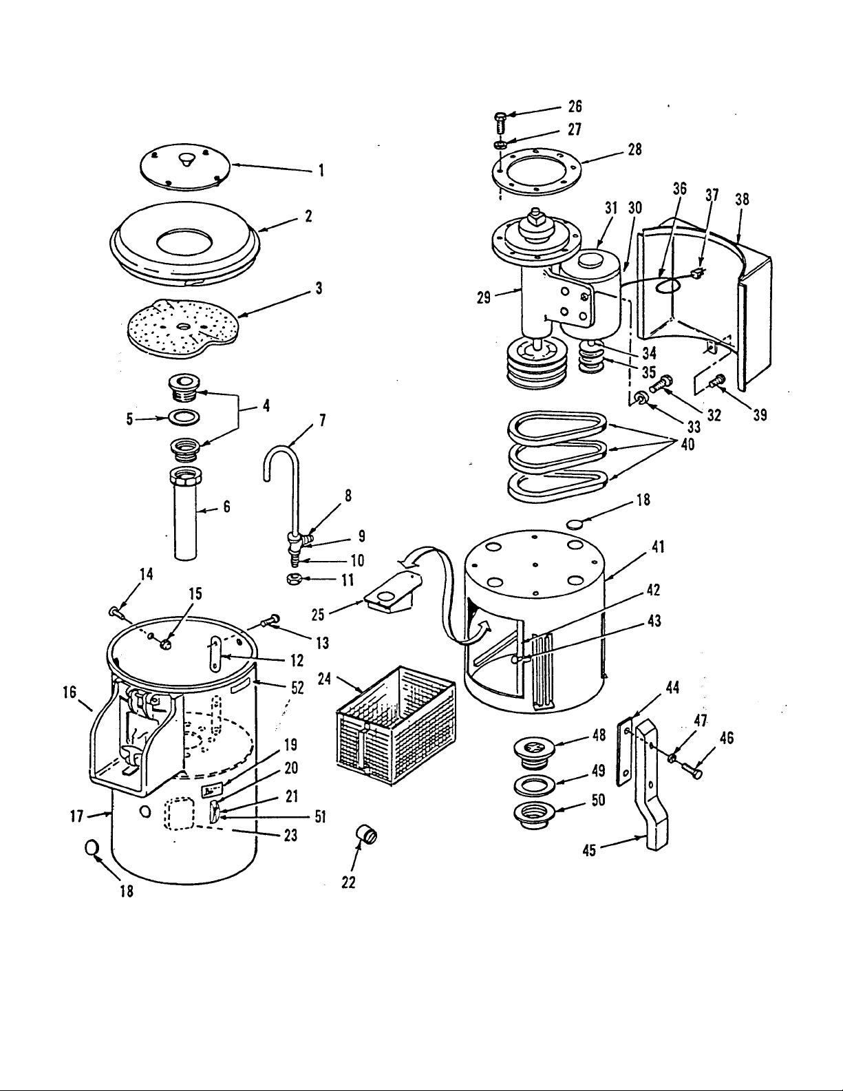
FIGURE 2
MODELS XC-15, XC-30 & XC-60 PEELERS
Page 5

MODELS XC
-
15, XC
-30 &
XC-60 PEELERS
Index
No.
1 P2-5100 P2-5100 P2-5100 SPLASH COVER 1
2 P2-5163 P2-5164 P2-5164 HOPPER, Plastic 1
3 P4-5270 P4-5271A P4-5109 PEEL DISC 1
4 P1-5291 P1-5291 P1-5291 DRAIN CUP, with flanged Locknut 1
5 P1.5292 P1-5292 P1.5292 GASKET 1
6 P1-5293 P1-5294 P1-5294 WASTE TUBE w/ Locknut and Rubber Washer 1
7 P1.5066 P1-5066 P1-5066 SPRAY PIPE 1
8 P1-17238 P1-17238 P1-17238 NIPPLE, Dixon Style 3500 1
9 P1-17236 P1-17236 P1-17236 TEE, 1/4 x 1/4 x 3/8" Female 1
10 P1-5210 P1-5210 P1-5210 STUD, 1/2x3" 1
11 WO-14192 W0-14192 WO-14192 LOCKNUT, 1/2 -13 Hex Jam Nut Cadm. Plated 1
12 P1-5272 P1-5272 P1-5272 LOBE, Peeler (XC-60 Qty. 3) 2
13 W1-10307 W1-10307 W1-10307 SCREW, 10/32 x 3/8" Ig. Rd. Hd. Mach. (XC-60 Qty. 6) 4
14 — W1-11545 W1.11545 SCREW, 10/24 x 1/4" Ig. Rd. Hd. Mach. 4
15 — P1-17252 P1-17252 NUT, 10/24 Cap 4
16 P4-5258 P4.5025 P4-5025 CHUTE AND DOOR ASSEMBLY (See Fig. 3 for Detail Parts) 1
17 P4-5212 P4-5231 P4-5232 HOUSING, Upper w/ Chute Casting 1
18 W1-7123 W1-7123 W1-7123 PLUG, Button 3
19 P1-5052 P1-5052 P1-5052 PLATE, Data 1
20 P1-5096 P1-5096 P1-5096 PLATE, Switch Cover 1
21 M1-15260 M1-15260 M1-15260 SWITCH, Toggle, 1 PH., Flush 1
21 P1-17203 P1-17203 P1-17203 SWITCH. Toggle, 3 PH., Flush 1
22 P2-5108 P2-5108 P2-5108 SWITCH, Timing, 1 PH. Only (Not Illust) (Opt) 1
22A — P2-5315 P2-5315 STARTER, 220/440V, w/115V Circuit Control (Opt) 1
23 P1-17250 P1-17250 P1-17250 ELECTRICAL BOX w/Cover 1
24 P4-5203 P4-5189 P4-5189 BASKET, Peel Trap 1
25 P3-5252 P3-5252 P2-5242 DEFLECTOR, Drain 1
26 W1-8148 W1-8148 W1-8148 CAPSCREW, 3/8 x 3/4" Ig.. S/S 8
27 W1-5567 W1-5567 W1-5567 WASHER, Plain 3/8" Cad. Pit. 8
28 P2-5040 P2-5040 P2-5040 GASKET 1
29 P4-5219 P4-5220 P4-5221 BEARING COLUMN ASSY, Complete (See Fig. 4 for Detail Parts) 1
30 M1-15388 M1-15388 M1-15388 CONNECTOR, 3/8"-90° (Not Illust.) 1
31 P1-5280 P1.5282 P1-5284 MOTOR, 1/3 HP (XC-15), 3/4 HP (XC-30), 1 HP (XC-60), 1 PH. 1
31 P1-5281 P1-5283 P1-5285 MOTOR, 1/3 HP (XC-15), 3/4 HP (XC-30), 1 HP (XC-60), 3 PH. 1
32 W1-7111 W1-7111 W1-7111 CAPSCREW, 5/16 x 3/4" Ig. Hex Hd. 4
33 P1-17235 P1-17235 P1-17235 LOCKWASHER, 5/16" 4
34 — P1-5155 P1-5155 KEY, 3/16" sq. x 2" Ig. 1
35 P1-5111 P1-5007 P1-5134 SHEAVE 1
35A P1-95068 P1-95067 P1-95067 SHEAVE for 50 Cycle Motors Only 1
36 P1-17214 — — CORD, No. 14 AWG, 3 Wire Conduct, 1 PH (Opt-XC-15 only) 6ft
36A M1-15369 — — CORD, No. 14 AWG, 4 Wire Conduct, 3 PH (Opt.XC-15 only) 6ft
37 P1-17212 P1-17212 P1-17212 PLUG, Use with 3 Wire Cord, 120V, 1 PH, 15 Amp. 1
37A M1-15374 M1-15374 M1-15374 PLUG, Use with 3 Wire Cord, 250V, 1 PH, 15 Amp 1
37B PO-17213 P0-17213 PO-17213 PLUG, Use with 4 Wire Co rd, 208/240V, 60C, 3 PH, 20 Amp 1
37C PO-95603 PO-95603 PO-95603 PLUG, Use with 4 Wire Cord, 460/480V, 60C, 3 PH, 20 Amp 1
38 P4-5207 P4-5196 P4-5196 HOUSING, Motor 1
39 W1-5987 W1-5987 W1-5987 SCREW. 10-24 x 1/2" Pan Hd. 1
40 P1-15211 P1-15211 — V-BELT, 31" Ig. (XC-15 & XC-30) 2
40 — — W1-8888 V-BELT, 32" Ig. (XC-60) 3
41 P4-5205 P4-5188 P4-5188 HOUSING, Lower Weldment 1
42 P2-17210 P2-17210 P2-17210 SLIDING DOOR, S/S 1
43 P1-17228 P1-17228 P1-17228 KNOB 1
43A P1-17244 P1-17244 P1-17244 #8 LOCKWASHER for Door Knob 1
43B W1-7476 W1-7476 W1-7476 SCREW for Door Knob 1
44 P1-5199 P1-5199 P1-5199 CLAMP BAR 4
45 P4-5195 P4-5195 P4-5195 LEG, Cast Aluminum 4
46 P1-17230 P1-17230 P1-17230 CAPSCREW, 3/8 x 1" Ig. Hex Hd. 8
47 W1-7524 W1-7524 W1-7524 LOCKWASHER, 3/8" Split 8
48 P1-17248 P1-17248 P1-17248 WASTE DRAIN, 2" Brass 1
49 P1-5236 P1-5236 P1-5236 GASKET 1
50 P1-17249 P1-17249 P1-17249 LOCKNUT, Pipe 2" 1
51 M1-95654 M1-95654 M1-95654 SWITCH GUARD 1
52 P1-95647 P1-95647 P1-95647 CAUTION LABEL 1
XC-15 XC-30 XC-60 Description Qty.
5
Page 6

FIGURE
3
DOOR ASSEMBLY
FIGURE
4
(Not Available As Assembly)
6
COMPLETE BEARING COLUMN
(Available As Assembly)
S-15 & XC-15 - P4-5219
XC-30 - P4-5220
XC-60 - P4-5221
Page 7

No.
Description
No.
Reqd.
1
1
1
5222
BEARING COLUMN (XC
-
60)
1
S-15 & XC-15
XC-30
XC-60
Item
Part
No.
1 P4-5014 DOOR, Peeler 1
2 P1-5036 SPRING 1
3 P1-5254 PIN, Hinge 1
4 P1-5035 PLUNGER 1
5 P1-5030 LATCH JAM 1
6 P1-5037 HANDLE, Latch 1
7 W-1-7598 LOCKWASHER, 5/16, S/S 1
8 W-1-8138 CAP NUT. Brass, 5/16-18 S/S 1
9 P1-17231 DRIV-LOK PIN, S/S 1
10 P1-5269 BALL PLUNGER 1
11 W1-8132 JAM NUT, 10/32 1
12 P-4-5024 CHUTE CASTING S-15, XC-15 1
12A
P-4-5051 CHUTE CASTING XC-30, XC-60
Item
No.
2 P2-5225 DRIVE SHAFT. Peel Disc (S-15, XC-15 & XC-30) 1
2 P2-5227 DRIVE SHAFT, Peel Disc (XC-60) 1
3 P1-5177 DRIVING BLOCK, Peel Disc 1
4 P1-17232 DRIV-LOK PIN, 1/4 x 2" 1
5 P1-17222 BUSHING, Plain 1
6 P1-17225 BEARING. Roller Cone 1
7 P1-17224 BEARING, Cup 1
8 P1-17233 PIPE PLUG, 1/8-27 N.P.T. 2
9 P1-5253 SPACER 1
10 P1-5274 OIL SEAL 1
11 P1-17229 PULLEY, 2 Groove (S-15, XC-15 & XC-30) 1
11 P3-5135 PULLEY, 3 Groove (XC-60) 1
12 P1-17242 KEY, 1/4" sq. x 1.1/2" Ig. . 1
13
Part
No.
P4P4-5224
W1-7171 SETSCREW. 5/16 x 3/8" Ig. Cup Pt.
Description No.
BEARING COLUMN (S-15, XC-15 & XC-30) Select One
Reqd.
1
1
7
Page 8

Item
FIGURE
4
No.
Part
No.
Description
No.
Reqd
1
1
2 P2 - 5225 DRIVE SHAFT, Peel Disc (S -15, XC-15 & XC-30) 1
2 P2 - 5227 DRIVE SHAFT, Peel Disc (XC -60) 1
3 P1 - 5177 DRIVI NG BLOCK, Peel Disc 1
4 P1 - 17232 DRIV.LOK PIN, 1/4 x 2" 1
5 P0 - 70170 BALL BEARING 1
6 P1 - 17225 BEARING. Roller Cons 1
7 P1 - 17224 B3ARING, Cup 1
8 P1 - 17233 PIPE PLUG, 1/8-27 N.P.T. 2
9 P1 - 5253 SPACER 1
10 P1 - 5274 OIL SEAL 1
11 P1 - 17229 PULLEY, 2 Groove (S -15, XC-15 & XC-30) 1
11 P3 - 5135 PULLEY, 3 Groove (XC -60) 1
12 Pl - 17242 KEY, 1/4" sq. x 1-1/2" Ig. 1
13 W1 - 7171 SETSCREW, 6/16 x 3/8" Ig.Cup Pt. 1
P4 - 5222
P4 - 5224
BEARING COLUMN (S -15, XC-15 & XC-30)
BEARING COLUMN (XC -60)
1
1
COMPLETE-BEARING COLUMN
(Available AB Assembly)
S-15 & XC -15 - P4-5219
XC -30 - P4-5220
XC -60 - P4-5221
Page 9

No.
1 3
1
1
1
1
1
1
1
1
Item
No.
1 5222 BEARING COLUMN (S-15, XC-15 & XC-30) 1
1 5224 BEARING COLUMN (XC-60) 1
2 73195 DRIVE SHAFT (S-15. XC-15 & XC-30) 1
2
4 17232 DRIV-LOCK PIN 1
5 70170 BALL BEARING 1
6 17225 TIMKEN CONE 1
7
8. 2255 SHAFT SEAL ASS'Y.
9 3488 RETAINING RING
10 73203 RETAINING RING
11 17229 PULLEY (S-15, SC-15 & XC-30)
11 5135 PULLEY (XC-60)
12
13
14 73198 SPACER 1
Part
No.
73196
73197
17224
17242
7117
DRIVE SHAFT (XC-60)
DRIVE BLOCK
TIMKEN CUP
KEY
SET SCREW
Description
Reqd.
1
Used on machines with serial number suffix A A B and up.
Figure 4A
Page 10

nt of potatoes for your type of
PEELER TROUBLE SHOOTING CHART
TYPE OF TROUBLE REASON CORRECTIVE MEASURE
Peeler will not start Main Fuse or Circuit Breaker Change fuses or reset circuit breaker
Wire loose or broken Overload switch tripped Push reset button Visually check all
Motor runs but peeler disc does not run Belt broken or slipping Adjust belt tension or replace broken belts
Peeler runs hot or smokes Improper voltage on motor or motor
defective Motor overloaded thus
overheating
Bearing column tight not free running Grease by removing plug at center bearing and
Peeler makes noise when running Worn out bearings Replace bearings
Peeler leaks water at the
center bearing
Peeler won't peel potatoes Worn peeler abrasive disc Replace abrasive disc
Defective seal Replace seal P1-5274 Also check the bearing
Peeler liner worn smooth
On models made prior
to 1-1-68
Peeler overloaded Use proper amou
connections, controls & motor Check switch
Check incoming voltage and motor Check
amperage draw
grease with an Elimite grease gun Use SHELL
DARINA 2 grease or equivalent
P1-17225 Timken Cone
P1-17224 Timken Cup
PI-17222 Bushing
and oil seal P1-5274
P4-5270 XC15
P4-5271 XC30
P4-5109 XC60
Replace liner with
P1-5272 peeler lobes
peeler (See Owners Manual)
Flat spots on Idaho potatoes Potatoes are too long Cut Idaho potatoes in half before inserting in
Water splashes out when peeling
potatoes
Water leaking on floor Peel trap basket full of peelings Empty peel trap basket
8
machine
Too much water pressure
or
Splash cover missing
Lower drain plugged up Clean or rod out drain
Turn water valve down to
regulate
Replace splash cover p/n P2-5100
Page 11

INSTRUCTIONS FOR INSTALLATION , OPERATION
Place your Blakeslee Peeler where the most evident operation is assured. The Peeler should be placed so
BLAKESLEE
&
CO.
AND MAINTENANCE OF BLAKESLEE
POTATO AND VEGETABLE PEELERS
INSTALLATION
that the peeled potatoes can be discharged into a sink. If your Peeler was supplied in the bench model, then
the Peeler should be Installed with room for the potatoes to discharge into a metal container so that the peeled
potatoes can be submerged in water, as peeled potatoes must be kept under water to prevent their turning black.
The Potato Peeler is equipped with a removable strainer basket that catches the peelings. This strainer basket is
removed through the access door in the base of the Peeler, so when installing your Peeler, be sure there is ample
room to permit easy removal of the strainer basket. NOTE: XC (floor) model peelers are shipped with the unload
door and strainer directly over one another. It is possible to have the strainer basket in a different position. Simply
remove the attaching bolts, move the bottom cylinder In increments of 90' until you obtain the desired position
and reinstall attaching bolts.
When you have selected the proper location for the Peeler, it is then necessary to connect the motor, the drain,
and make a cold water connection to the spray inlet on the top of the Peeler. Before making the electrical,
connection, be sure that the electrical specifications on the tag attached to the motor correspond to the available
electrical current. The drain pipe should be 2" or larger all the way with as much downward pitch as possible and
without any sharp bends for good drainage. A 3/8" cold water supply line should be connected to the back of the
machine. A hose bibb, to which a hose may be attached, is recommended for cleaning the Peeler after It has been
used.
OPERATION
Before operating the Peeler, be sure that the peeling disc and cover and the peel trap strainer basket are all In
place, then adjust the cock or valve for the correct flow of water into the peeling chamber. Next turn on the
motor and then put in the potatoes. Be careful not to overload the machine as when the peeling chamber is
overloaded, the potatoes will not tumble and roll properly and there will be more waste than is necessary.
Overloading the peeling chamber can also cause uneven peeling, or what is commonly called "flats". When
peeling long Idaho potatoes, it’s often advisable to cut them in half for efficient peeling. Always be sure to
turn on the motor the peeling disc is In motion before the potatoes are dumped into the peeling chamber, as
filling the peeling chamber first and then starting the motor tends to overload the motor and the potatoes do
not tumble and roll for even peeling. It is very desirable to have a container as a measure that will hold Just
the right quantity of potatoes, 15, 20 or 60 Ibs., as the model indicates, as such a measure is insurance against
overloading.
The time required for peeling a charge of potatoes depends greatly on the condition and age of the potatoes.
New potatoes are peeled very quickly, whereas old potatoes require a longer time for peeling. Potatoes that are
being peeled for potato chips are generally peeled very lightly. Potatoes that are going to be mashed should be
peeled more thoroughly. The progress of the peeling can be watched and sometimes It Is advisable to lift out
a-few potatoes to examine the extent of the peeling that has been accomplished.
To discharge the peeled potatoes, merely open the door of the peeling chamber and the peeled potatoes will
automatically throw out. After the peeled potatoes have been discharged, turn off the water and the motor. Do
not peel the eyes out of the potatoes as it is much more economical to trim out the eyes by hand after peeling.
When peeling large quantities of potatoes, empty the peel trap strainer basket frequently.
CLEANING
When all of the potatoes and vegetables have been peeled, and before the inside of the peeler has had time to dry. remove the cover, and the peeling
disc and hose out the Inside of the peeler. Always remember to empty and clean the peel trap strainer basket.
CAUTION: Be sure motor is connected so peeling disc
operates in clockwise direction. This Is very important
as if motor is running backwards, peeler cover will fly
off when potatoes are being peeled.
Ocero, Illinois 60650
BLAKESLEE & CO., LIMITED
Scarborough, Ontario MIR/363
 Loading...