

Page 1
UNDERCOUNTER DISHWASHER
OWNER'S MANUAL
BLAKESLEE
BL
AKESLEE
MODEL UC-21
I.R.S. INTEGRATED RECIRCULATING SYSTEM DESIGN
1844 South Laramie Avenue
Chicago, IL 60650
Phone: (708) 656-0660
66 Crockford Boulevard
Scarborough Ontario, Canada M1R 3C3
Phone: (416) 751-2625
Page 2

INDEX
gpm
Installation Instructions* 1
Operating Instructions 2
Maintenance Instructions 3
Illustrated Parts List 5
Recommended Spare Parts List 17
* Installation must be made observing applicable
plumbing and electrical codes.
SPECIFICATION
Page
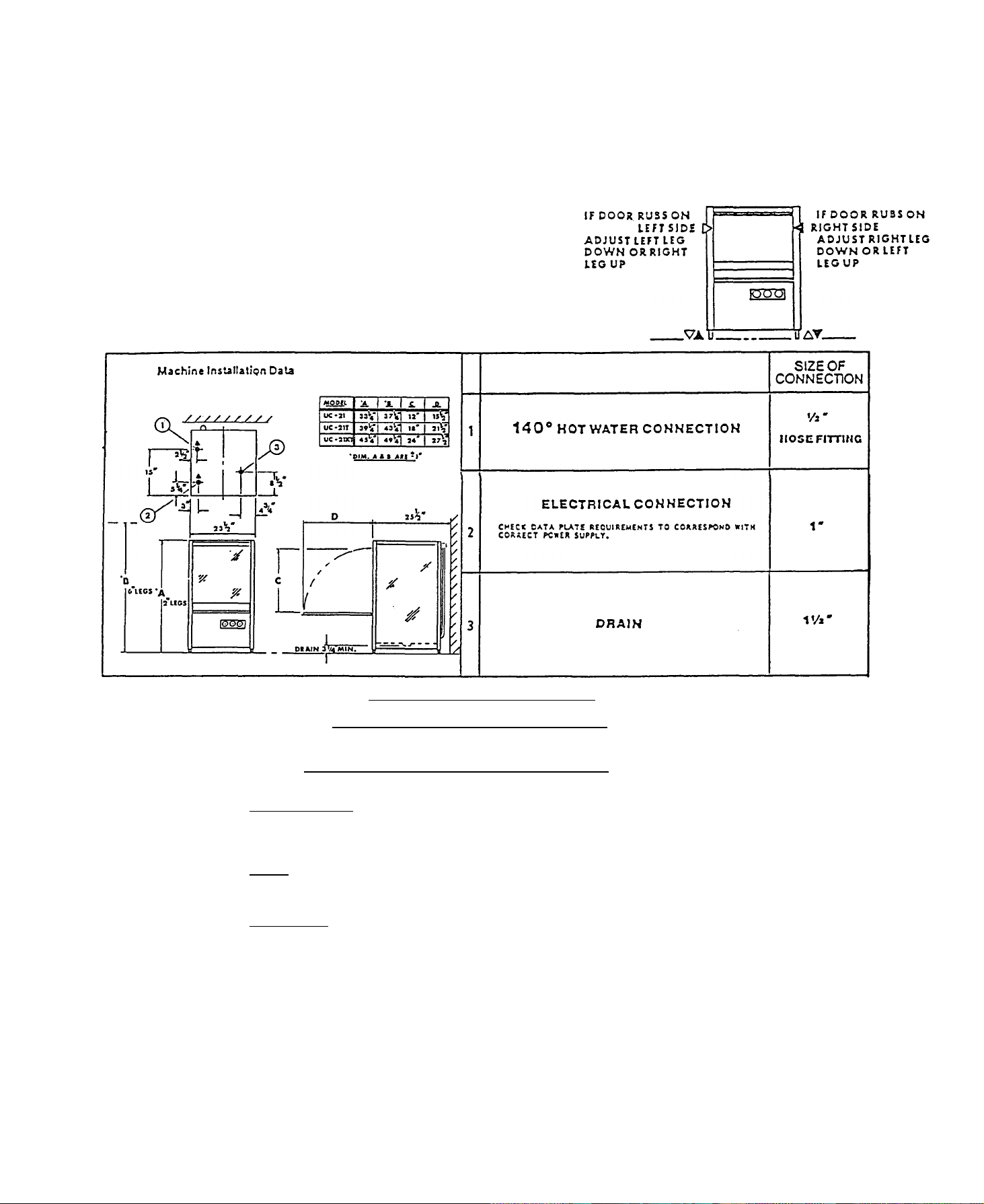
Construction: MACHINE INSTALLATION DATA:
Body of stainless steel con Electrical
struction throughout. Volts Phase Load AMPS
Wash System: 220 1(4 wire) 48.6
Top and bottom counter rotat - 220 3(5 wire) 27.0
ing spray arms.
Rinse System:
Top and bottom counter rotat - Inlet Temperature 140°F
ing spray arms. * Inlet Pressure 20 psi
Recirculating System: Inlet Flow 6
Horsepower 1 Water Consumption 30.5 gph
Hash Tank Capacity: Wash and Rinse Cycle
6.0 gal. Wash time - 105 seconds. Dwell
Water Heating: 12 seconds. Total cycle An electric immersion heater 120 seconds.
rated at 9.0 kw heats both
the wash and rinse water
Control: at the connection point of the
Automatic wash/rinse cycle dishmachine.
control. Thermostatically con
trolled rinse temperture.
Water Supply
Inlet Size 1/2 Hose
time 5 seconds. Rinse time
* Inlet pressure should be measured
Page 3
Installation
The Model is suitable for both under the counter and free standing installations. Access is
required to both the sides and rear of the machine for service and maintenance. Therefore, all
connections should be made with flexible hoses and conduit to ensure that access can be
achieved.
Level machine by adjusting legs as necessary, while
maintaining counter clearance dimensions.
NOTE: If machine is not leveled properly, door
will not close correctly.
INSTALLER WARNING!
TO PROTECT BOOSTER HEATING ELEMENT
DO NOT TURN ON ELECTRICAL POWER SUPPLY TO DISHWASHER
UNTIL WATER SUPPLY HAS FIRST BEEN CONNECTED AND YOU ARE
READY TO PROCEED WITH ACTUAL TEST OPERATION OF MACHINE !
WATER SUPPLY
Connect incoming water supply hose to 1/2" I.D. Hose fitting. Water supply source must be
able to provide 1400 F, water minimum at 20 PSI flow pressure.
DRAIN
Connect 1-1/2" drain tube to waste connection.
ELECTRICAL
Check machine data plate before making any electrical connections. All supply
connections must correspond with data plate information.
-1-
Page 4
Operation
CAUTION
DO NOT ATTEMPT TO OPERATE WITHOUT WASH TANK BEING
PROPERLY FILLED, AS DRY ROTA TION WILL DAMAGE MOTOR SEALS
AND VOID WARRANTY.
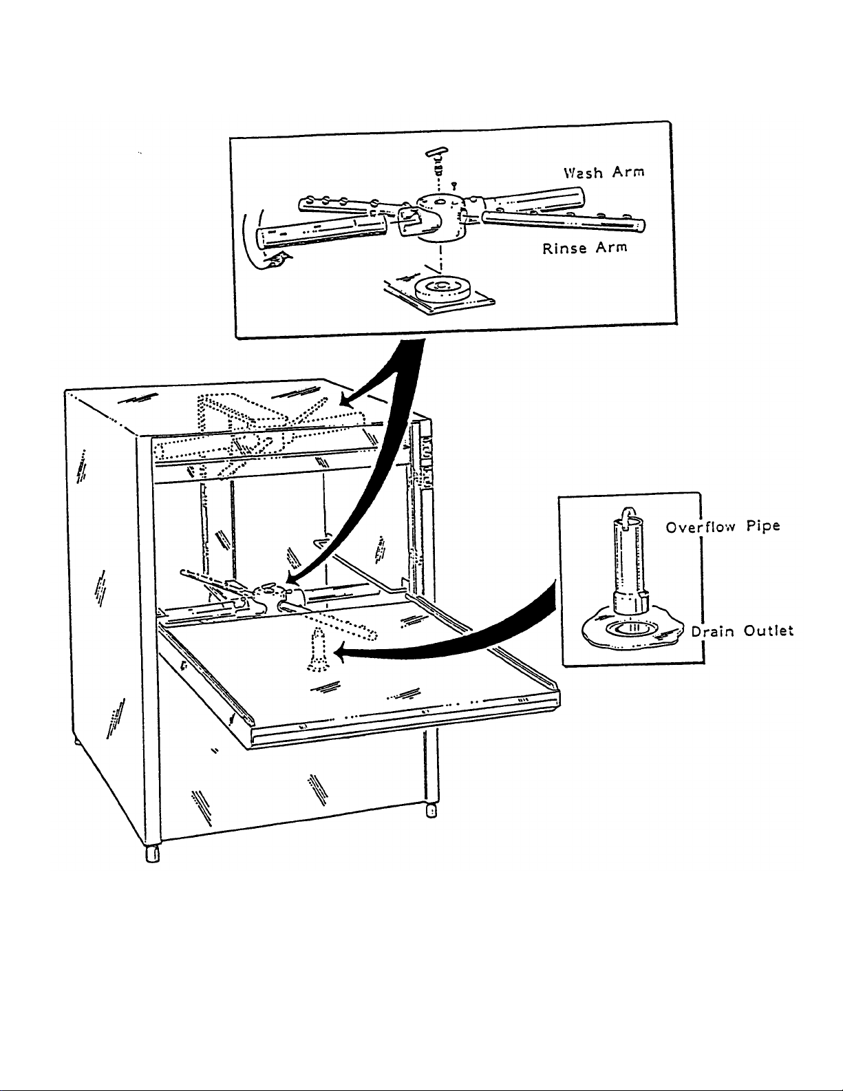
Ensure that all spray arms spin freely and that pump strainer cover and
drain riser pipe are properly installed.
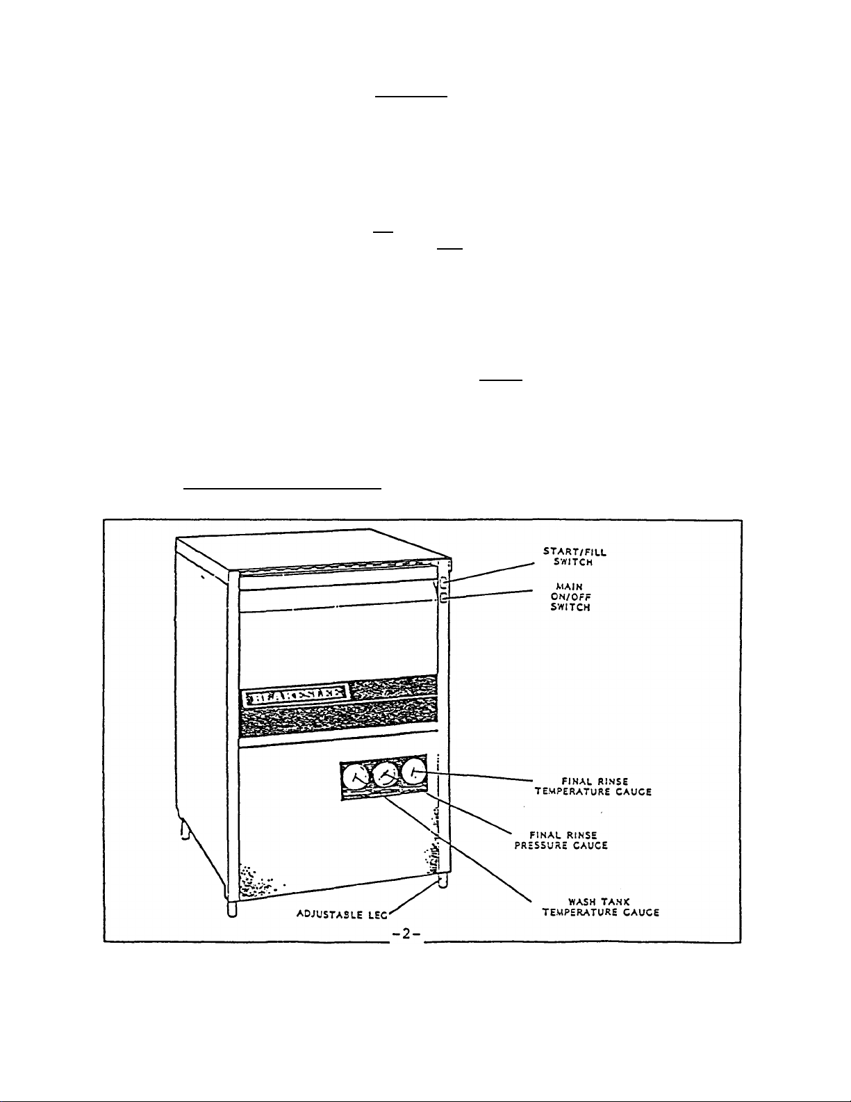
Depress On/Off main switch to ON position. Switch light will indicate power is on.
Close door. Depress and hold Start/Fill switch in FILL position for 50 seconds or until
water can be heard flowing down drain.
If detergent is fed manually, prep full tank of fresh water with 3 oz. of a low suds
detergent, then 1 oz. per each cycle there after. Increase or decrease detergent rate
based on results.
Insert properly pre-scrapped and pre-flushed racked ware.
Close door, depress and hold Start/Fill Switch in START position. Lighted
switch will indicate machine is operating.
Cycle is completed when Start/Fill switch indicator light turns off.
Open door and remove cleaned ware.
Washing operation is completed.
Page 5

Maintenance
After each washing period, pull out the overflow drain tube and wipe down the inside of
the washing tank with a damp cloth. At the end of the day, remove both spray arms and
check that none of the jets are obstructed. Rinse down the inside of the washing tank
with fresh water and leave the door open over night to dry out the tank.
UNSATISFACTORY WASHING RESULTS
1. If grey hard deposits appear on the inside of the tank, you are using an
unsatisfactory detergent or the wrong dilution.
2. If a fi lm of grease appears inside the wash, it could be caused by:
A. Lack of detergent
B. Insufficient water flow on the rinse cycle
C. Tank water may require changing
3. If the dishes are spotted with water, it may be because of:
A. Insufficient water fl ow on the rinse cycle
B. Clogged nozzles on the rinse spray arms
C. The angle of the nozzles on the rinse spray arms may need adjustment to
ensure that the rinse water is sprayed uniformly throughout the wash tank
4. If spray arms do not rotate, look for clogging in the spray arms.
5. If the wash tank foams excessively, it may be because the wrong detergent has
been used. Excessive rinse aid also causes this problem.
6. If the machine stops during a wash cycle and fails to restart, check that the door is
properly closed.
-3-
Page 6
CLEANING BREAKDOWN ILLUSTRATION
-4-
Page 7

Figure 1. Recirculating System
-5-
Page 8

1
1
1
1
FIGURE 1. RECIRCULATING SYSTEM
ITEM
NO.
1 17798 MOTOR 1 H.P., 115/230V, 1 PH 1
1A 8247 MOTOR 1 H.P., 208/240V, 480V, 3 PH 1
2
3 7117 SETSCREW, 5/16 X 3/8 2
4
5 14785 3/8-16 HEX NUT 4
6 17245 3/8" LOCK WASHER 8
7 7522 3/8" FLAT WASHER 8
8 7656 3/8-16 X 1" HEX HD. CAPSCREW 4
9
10 2255 PUMP SEAL ASS'Y. 1
11 95252 IMPELLER SPINDLE 1
12 1658 3/16 SQ. X 3/4" LG. KEY 1
13
14 5587 FLAT WASHER 1
15 7598 5/16" LOCK WASHER 1
16 7621 5/16-18 X 3/4" S.S. H.H.M.S. 1
17 17762 IMPELLER ASSEMBLY
PART
NO.
17794
74505
75004
95673
DESCRIPTION
COLLAR
MOTOR MTG. BRACKET
O-RING
IMPELLER
INCLUDES ITEMS 11, 12, 13, 14. 15 & 16
QTY.
REQ.
-6-
Page 9

FIGURE 2. SPRAY ARMS & MANIFOLDS
-7-
Page 10

4
2
FIGURE 2. SPRAY ARMS & MANIFOLDS
ITEM
NO.
1 75000 WASH MANIFOLD 1
2
3 70087 RINSE ARM NOZZLE 20
4 70083 WASH ARM 4
5 70060 SPRAY ARM KNOB 2
6 09917 RINSE ARM ADJUSTMENT SCREW 4
7 70081 SPRAY ARM ASSEMBLY 2
8
9 70089 BUSHING 4
10 70082 HUB ASSEMBLY 2
11 74691 RINSE BLOCK CONNECTOR 2
12 74693 COMPRESSION RING 2
13 74692 COMPRESSION NUT 2
14 74649 LOWER RINSE MANIFOLD 1
15 13986 COMPRESSION TEE 1
16 70044 UPPER RINSE MANIFOLD 1
17 75001 RISER WELDMENT 1
PART
NO.
70086
70088
DESCRIPTION
RINSE ARM
INCLUDES ITEMS 2, 3, 4, 6 & 10
HUB
INCLUDES ITEMS 8 & 9
QTY.
REQ.
-8-
Page 11

FIGURE 3. ELECTRICAL ASSEMBLY
-9-
Page 12

1
1
2
-10-
FIGURE 3. ELECTRICAL ASSEMBLY
ITEM
NO.
1 70154 SWITCH FILL/START 1
2 70153 SWITCH ON/OFF HEAT 1
3 70431 SWITCH LABEL WASH/START 1
4
5 74217 FLOAT SWITCH 1
6 74602 LIMIT THERMOSTAT 1
7 74599 IMMERSION HEATER 9 KW, 230V 1
7A 71904 IMMERSION HEATER 1.5 KW, 240V 1
7B 71720 IMMERSION HEATER 1.5 KW, 115V 1
8
9* 74964 HEATER COVER 1
10 74114 GROUND LUG 1
11 70191 POWER TERMINAL STRIP 1
12 16779 FUSE 1
13 70190 CONTROL TERMINAL STRIP 1
14 7768 THERMOSTAT 1
15
16 70192 MOTOR CONTACTOR 1
17 71603 OVERLOAD RELAY 7-10 AMP 1
17A 71601 OVERLOAD RELAY 4-6 AMP 1
17B 71605 OVERLOA D RELAY 13-18 AMP 1
18 7210 HEAT CONTACTOR 60 AMP 1
18A 7209 HEAT CONTACTOR 30 AMP 1
19 74980 CYCLE TIMER 1
PART
NO.
71335
75024
14246
DESCRIPTION
DOOR SAFETY SWITCH
GASKET-IMMERSION HEATER
RELAY
QTY.
REQ.
*NOT ILLUSTRATED.
Page 13

FIGURE 4. BODY ASSEMBLY
-11-
Page 14

1
4
1
1
FIGURE 4. BODY ASSEMBLY
ITEM
NO.
1 71594 TOP COVER 1
2 70440 REAR PANEL 1
3
4 70437 DOOR SPRING 2
5
6 74377 FRONT PANEL 1
7 71592 PANEL L.H. 1
8 74655 DOOR 1
9 74227 DOOR HANDLE 1
10 71591 HINGE COVER PANEL 1
11
12 70140* DOOR SWITCH MOUNTING BRACKET 1
13 72724 COILED SPRING PIN 2
14 71553 DOOR HINGE L.H. 1
15 71688* DOOR HI NGE R.H. 1
16
17 74653* DOOR SEAL RETAINER - LOWER 1
18 74654* DOOR SEAL - LOWER 1
PART
NO.
71593
70064
97844*
72625*
DESCRIPTION
PANEL R.H.
ADJUSTABLE FOOT
BLAKESLEE LOGO
UPPER DOOR SEAL
QTY.
REQ.
-12-
Page 15

FIGURE 5. PLUMBING & GAUGES
-13-
Page 16

1
1
1
2
1
1
1
1
FIGURE 5. PLUMBING & GAUGES
ITEM
NO.
1 70201 3/8" VACUUM BREAKER 1
2 72632 3/8" TO 1/2" TUBE ELBOW 2
3
4 72570 VACUUM BREAKER TUBE 1
5
6 70765 OUTLET DRAIN ASSY. 1
7 72630 MALE CONN. 3/8" TO 1/2" TUBE 2
8 72560 FLARED FITTING NUT 1/2" 4
9
10 13884 3/4" X 1/2" X 1/2" BRASS TEE 1
11 18528 1/2" BRASS PIPE PLUG 1
12 12495 1/2" X 90° BRASS STREET ELBOW 1
13 70348 1/2" X 3/8" REDUCING BUSHING 2
14 72641 3/8" X 8" BRASS NIPPLE 2
15 70200 3/8" SOLENOID VALVE 1
16
17 70155 THERMOMETER 2
18 70156 PRESSURE GAUGE 1
19
20 70204 3/8" X 3/8" X 3/8" BRASS TEE 1
21
22 72564 MALE CONN. 1/4" NPT TO 1/4" TUBE 1
23 72561 FLARED FITTING NUT 1/4" 2
24
25 70206 3/8" X 90° STREET ELBOW 2
26 70393 1/2" HOSE NIPPLE 1
27 70099 1/4" X 90° BRASS ELBOW 1
PART
NO.
72569
74960
70395
70441
70392
72631
72568
DESCRIPTION
INLET TUBE
STANDPIPE
* DRAIN CUP
* O-RING 1
* LOCKNUT 1
3/8" CLOSE NIPPLE
INSTRUMENT DATA PLATE
1/2" LINE STRAINER
3/8" TO 1/4" TUBE CONNECTOR
GAUGE TUBE
QTY.
REQ.
-14-
Page 17

 Loading...