

Page 1
BLAKESLEE
20 QUART: Models B-20, F-20, U-20
OWNERS
MANUAL
Division of Blako Inc.
ELECTRIC FOOD MIXER
30 QUART: Model F-30
1844 South Laramie Avenue
Chicago, IL 60804
Phone (708) 656-0660
Fax (708) 656-0017
www.blakesleeinc.com
service@blakesleeinc.com
1149 Bellamy Road North Unit 19
Scarborough, Ontario Canada M1H1H7
Phone (416) 751-2625
Fax (416) 751-8539
Revision 8/2005
Page 2

INDEX
General Information
Installation Instructions
Design and Use Of Beaters, Whips and Other Accessories
Mixing Instructions
Mixing Bowl Capacity Chart
Available Beaters, Whips and Accessories
Operation
Parts Section:
Figure 1. Column Weldment 14
Figure 2. Bowl Support 16
Figure 3. Power Bowl Lift 18
Figure 4. Motor Mounting Bracket Assembly 20
Figure 5. Motor & Power Train 21
Figure 6. Auxiliary Hub Assembly 22
Figure 7. Lower Planetary 23
Figure 8. Planetary & Beater Shaft 24
Figure 9. Transmission Housing Assembly 25
Wiring Diagrams
Electrical Components
Service & Parts Distributors
Warranty
Page
1
2
5
7
9
11
12
13
30
34
35
37
Page 3

GENERAL INFORMATION
Your Blakeslee Mixer is just one piece of equipment that provides extra profit in your operation.
Consistency of performance will reduce waste and maintain better control over yield.
Your Blakeslee-built mixer has been designed and engineered to assist you in the quick and easy
preparation of fine tasting, quality foods. It is a valuable machine deserving the same maintenance
and attention your other kitchen equipment now receives. By following the suggestions in this
booklet, your mixer will operate for many trouble-free years.
This booklet has been prepared to give you the necessary knowledge for correct operation, load, and
lubrication of your mixer.
The food service operator will also be able to save you labor during the cleaning process due to the
smooth surfaces and design of the Blakeslee mixer. Each beater, whip and attachment is engineered
to perform specific jobs for you. The planetary action of Blakeslee Mixers (beater travels around the
circumference of the bowl as it rotates) assures you of a perfectly blended mix every time.
Diagram shows complete coverage of
Bowl by planetary action of beaters
-1-
Page 4
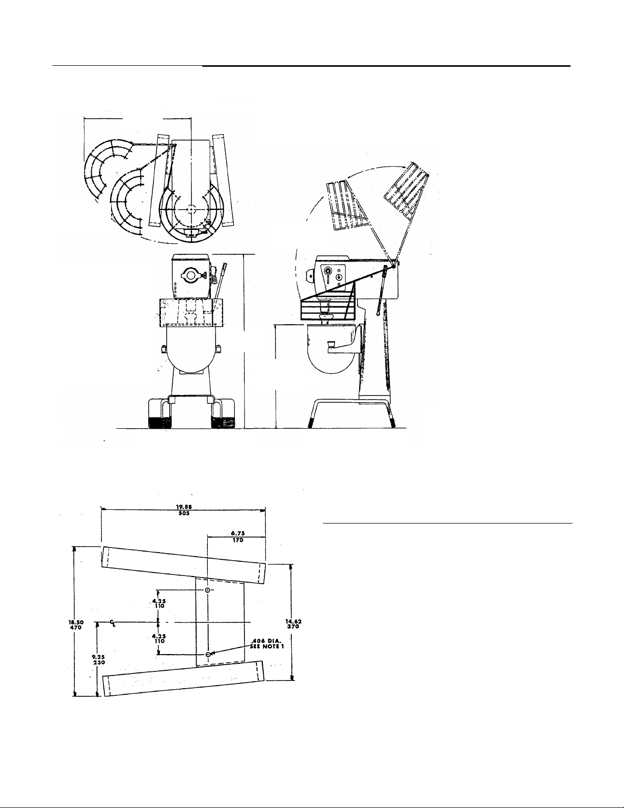
Installation Instructions
y
26.25
670
Travel
Bowl Guard
Travel
Bowl Guard
40.75
10.35
26.50 675
Raised Position
Shown With Type “A” Bowl Guard Shown With Type “B” Bowl Guard
NOTE: Holes used for shipping and mounting unit to floor
BENCH MODEL – B20
Select a location for your mixer that will save time
and steps for the operator. Allow ample work
space in front and to the sides of the mixer.
Mixer should be mounted to a sturdily built table
or bench approximately 25 inches high. Mounting
mixer to bench will insure against mixer slipping
on wet surface or tipping over from pressure
exerted as attachments are used. Refer to
mounting hole dimensional diagram.
Drill (4) 13/32” dia. Holes in table or bench top per
dimensions shown. Secure from underside of
table with (4) 13/32” – 16 bolts (length as required
b
thickness of bench top).
-2-
Page 5
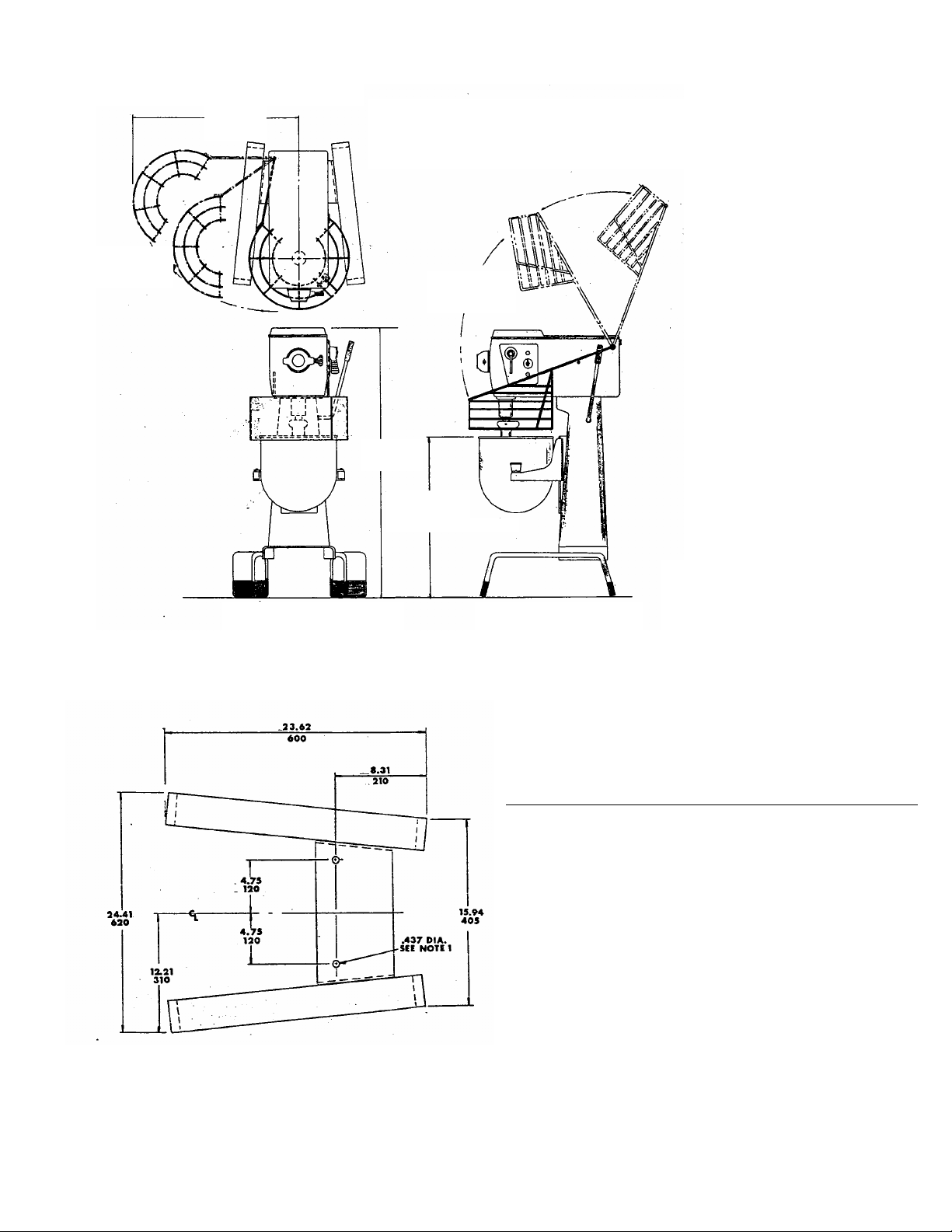
26.25
670
Travel
Bowl Guard
45.75
1160
Shown With Type “A” Bowl Guard Shown With Type “B” Bowl Guard
NOTE: Holes used for shipping and mounting unit to floor
30.00 760
Raised Position
Travel
Bowl Guard
-3-
FLOOR MODELS – F20, F30
Select a location for your mixer that will save time
and steps for the operator. Allow ample work space in
front and to the sides of the mixer.
Holes are provided for anchoring the mixer to the
floor, but unless desired bolting to the floor is not
necessary except on shipboard use.
Page 6
GENERAL FOR ALL MODELS
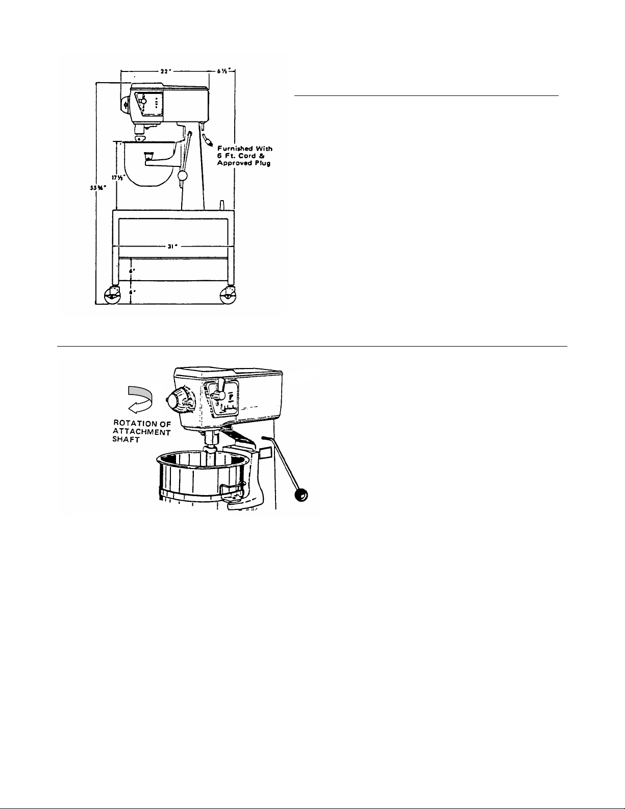
PORTABLE MODEL – U20
Available only in 20 quart size.
1. Store beaters and whips at rear of table top.
2. Lock all 4 casters before using mixer.
3. Refer to General Installation instruction for further
information.
1.
2
Electrical Connections
CAUTION: Before making electrical connections be sure that current and voltage of the
mixer are identical to those of electrical inlet lines.
20 quart, 110 volt mixers are furnished with a six (6) foot flexible power cord.
On 30 quart mixers the line cord is to be supplied by the customer. Connections are made
inside the mixer column through the cover plate located on the back side of the column
near the bottom. NOTE: A six (6) foot flexible three (3) prong cord is available as an extra
cost option.
IMPORTANT: On 3 phase mixers, after electrical connection has been made, be sure the
mixer operates in a counter-clockwise direction as indicated by the arrow located above
the attachment. If electrical connection is reversed the transmission will not shift, nor will
the planetary action function.
Transmission Oil
After the first 200 hours of operation and every 6 months thereafter the transmission oil
must be changed.
When adding or changing transmission oil use 50 S.A.E. heavy duty oil. 3 pints required.
-4-
Page 7
Design and use of Beaters Whips & Other Accessories
Each beater and whip has been designed to do a particular type of work. Use only that beater or whip
for the work for which it was designed. For example: never use a batter beater for mixing heavy
dough’s. Always use a dough hook for dough work.
Following are illustrations of the different types of beaters and whips with an explanation of the work
and use for which they were designed.
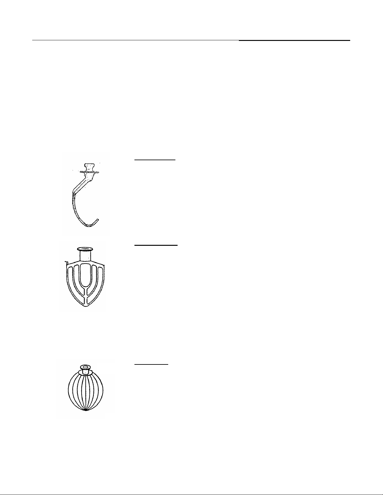
Dough Hook
Used for mixing bread or roll dough of standard consistency, biscuits,
meat loaf, etc. Dough hooks should always be operated at low
speeds only. Do not use other types of beaters for dough work;
doing so will result in damage to either the beaters or the mixer
proper.
Batter Beater
Used for mixing batters such as cake and muffin batters, creaming
butter, mashing potatoes and vegetables, light cakes, icings and the
average run of light work. Never use this beater for heavy dough
work. When mashing potatoes, etc. it is advisable to start with the
bowl at its lowest position and as the potatoes or other ingredients
break up, the bowl should be raised to its working position. This
procedure eliminates severe strain to the beater and to the mixer
proper and consequently adds to their life and efficiency.
Wire Whip
Used for whipping, creaming, beating eggs, meringues, small
amounts of mayonnaise, icings and for whipping milk or cream into
mashed potatoes after they have been broken up with a batter beater
-5-
Page 8
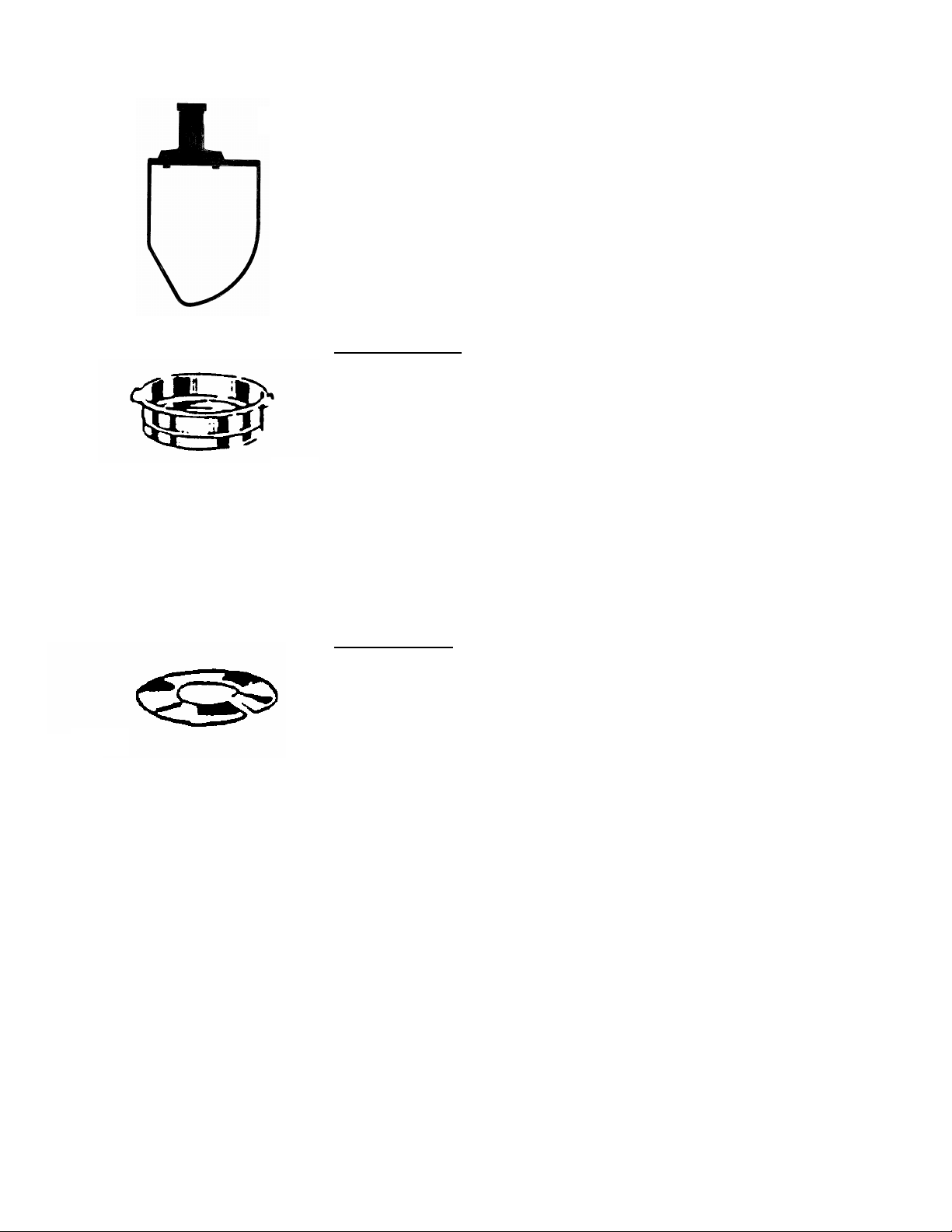
“PK” Pastry Knife
Used for cutting flour and shortening together in a pie dough, pastry
shells and for cutting lard or shortening into flour. The “PK” pastry
knife should always be used for such work so that pie crusts, etc, are
mixed with as little rubbing as possible and so that the shortening will
be in small pieces to produce a flaky product.
The true capacity of a mixer is not the amount of material that can be put in the bowl or the amount of
the total batch which can be mixed with in the power of the motor. The true capacities and the most
efficient (therefore the best money makers) are the ideal loads which permit a Mixer to operate at
peak efficiency, so far as development, yield or aeration have their effect on the mixing operation.
They are convenience items, not capacity increasers. The best functioning of Blakeslee mixers
depends on leaving room for proper material aeration or manipulation. Use splash covers or
extenders only for containing ingredients. They are efficient for their intended use, but if a mixer is
overloaded and a Splash Cover is used, aeration is reduced due to restriction in the area where air
enters the mix. The capacity chart located on the column of the mixer is a good guide for maximum
efficient use for the Mixer. Experience will have to dictate exact top capacity and Splash Cover use
under your own needs.
Bowl Extension
Extension Rims are merely vertical sided splash covers. They are
not covers in form but do provide higher side walls to prevent throwout of ingredients. Usually they are not recommended because they
are invitations to overloading a machine beyond its point of maximum
efficiency. Extension rims permit more air to enter the bowl and
prevents splash of light ingredients.
Splash Covers
These items provide means for providing splash of throw-out on
certain mixers when, for reasons of speed, the operator prefers to
start in a higher speed or progress quickly to a high speed in order to
complete a batch. These are valuable accessories but would not be
used to increase the mixing capacity of any particular machine,
beyond its recommended maximum.
-6-
Page 9
Mixing Instructions
FOR BEST
RESULTS
Operators have their own particular ways of operating their
mixing machines, so no attempt will be made to set up iron
clad instructions, but there are certain general principles that
should be followed in the various operations. These general
principles as listed below should be helpful to old and new
operators.
General Points for Proper Operation
NOTE
Refer to Mixing Chart before filling bowl.
1. In general, start all mixing at slow speed.
2. Always return to neutral position when
finished with a mix.
3. Gradually raise bowl and its contents to
the working position.
4. Bowl should be filled to at least half
capacity to achieve best results.
5. Make sure that bowl-to-beater clearance
is about 1/8”. Place a 1/8” layer of paper
on bottom of bowl to check bowl-to-beater
clearance.
Electrical
“Start-Stop” Push buttons are used to operate the
mixer. There is a thermal overload device with
automatic resetting for protection, internally
mounted. On all machines over 250 volts primary,
a transformer is supplied to reduce voltage to the
pilot circuit.
A timer shuts off the machine in any speed after
the pre-set time has expired. Normal operation is
obtained by setting the timer to “Hold” position.
When the timer is set at “O”, the start button
becomes a jog button, permitting intermittent
operation at the push of a button.
-7-
Whipping Cream
The wire whip (refer to Beaters and Whip chart)
should be used for whipping cream. Cream to be
whipped should be 24 hours old, should contain
30% butter fat and should be well chilled, in fact
near freezing temperature is desirable, since the
cooler the cream the better the whipping. Warm
cream may turn into butter instead of whipped
cream. To prevent splashing out of the bowl,
start whipping the cream at low speed and
increase the speed as the cream thickens.
Egg Whites
Use the wire whip and be sure the eggs are at
room temperature and that both the mixing bowl
and wire whip are free from all traces of fat or oil,
or egg whites won’t whip. In some installations
one bowl will be kept and used exclusively for
beating egg whites. Another bowl will be kept
and used exclusively for the oily type mixes.
Start beating the eggs at low speeds and
gradually increase the speed.
Meringues
Use the wire whip. Meringues can be made
perfect by the gradual addition of sugar to egg
whites which have not been too stiffly beaten.
Page 10

Mashing Potatoes
Use the batter beater and pre-heat the bowl and
beater. Lower the mixing bowl before putting in
the potatoes to be mashed then gradually raise
the bowl to its working position.
Start the operation on low speed. When the
potatoes have been broken up, stop the mixer
and add milk or cream, butter and seasoning.
Many operators like to change to the wire whip for
whipping in the milk or cream since more of a
whipping action is obtained to produce a fluffier
mashed potato.
Cake Batters and Cookie Dough
Use the batter beater. Butter or shortening can
be thoroughly creamed in about 10 minutes. The
butter or shortening should be at room
temperature. Always lower the mixing bowl
before putting in the ingredients then gradually
raise the bowl to its working position.
Sugar should be added to recipes at a medium
speed. When all of the sugar has been added,
stop the mixer and scrape down the sides of the
mixing bowl with a spatula to insure a smooth
mix. Be careful not to add sugar until the butter
or shortening has been thoroughly creamed.
When adding dry ingredients, stop the mixer
occasionally and scrape the upper part of the
bowl with a spatula to make sure that every
portion will be efficiently mixed into the recipe.
Always operate the mixer on slow speed while
adding dry ingredients. Add dry ingredients
alternately with liquid, starting and ending with dry
ingredients. Do most of the beating before the
flour and milk are added. Over beating after
these two ingredients causes a sub-standard
mixture.
Mixing Dough
Always use the dough hook for mixing heavy
doughs. Do not overload the mixer with too large
batches. (See the capacity chart on page 7.)
When using the dough hook, the mixing should
be started at low speed only. The bowl should be
in its lowest position gradually raised to working
position. Remember – an increased mixing time
means a decreased fermentation time. Weighing
materials each mix time will insure a standard
product. Stop the mixer occasionally to lower the
dough mass from the hook and to scrape the
bowl.
Important – In mixing heavy doughs be sure to
use the dough hook, be sure not to overload the
mixer (see capacity chart on page 7,) and be sure
to start the mixer on low speed with the bowl in
operating position.
Biscuit Mix
Use “W” wire whip and bowl extension ring (to
confine ingredients to bowl). Mix shortening and
dry ingredients until shortening is blended and
mixture is granular in appearance. Turn off
mixer. Scrape bowl down with bowl knife. Store
in covered can until ready for use. Use beater or
dough hook when adding liquid; start mixing on
slow speed and bowl in lowest position, then
gradually rise to the working position. Do not
over mix.
Pastries
Use the “PK” pastry knife, as pastries should be
mixed with as little “rubbing” as possible. The
“PK” pastry knife leaves the shortening in small
pieces to produce a flaky product. Remember,
over-worked dough makes tough pastry, and
working in too much flour tends to toughen
pastry.
Sweet Dough
For best results use the “SD” sweet dough
beater.
-8-
Page 11

Mixing Bowl Capacity Chart
CAPACITY OF BOWL
(Finished Material)
KITCHEN MATERIALS 20 Qt. 30 QT.
Egg whites 1 qt. 1 ½ qt.
Mashed potatoes 15 lbs. 23 lbs
Mayonnaise (qts. Of oil) 10 qts 12 qts
Meringue (pts. Of water) 1 ½ Pts. 2 pts.
Waffle or Hot cake batter 8 qts. 12 qts
Whipped cream 4 qts. 6 qts
BAKE SHOP MATERIALS
Angle Food (8 to 10 oz. cake) 15 22
Box or Slab Cake 21 lbs. 30 lbs.
Cup cakes 22 doz. 33 doz.
Layer cakes 20 lbs. 30 lbs.
Pound cake 21 lbs. 30 lbs.
Short sponge cake 15 lbs. 23 lbs.
Sponge cake batter 21 lbs. 18 lbs.
Sugar cookies 35 doz. 50 doz.
Bread or roll dough (60%AR) 25 lbs. (1) 45 lbs. (1)
Noodle dough 8 lbs. 10 lbs.
Pie dough (50%AR) 17 lbs. 27 lbs.
Pizza dough (65%AR) 14 lbs. (1) 21 lbs. (1)
Raised donut dough 9 lbs. (2) 15 lbs. (2)
Eggs & sugar (for sponge cake) 8 lbs. 12 lbs.
Fondant icing 12 lbs 18 lbs.
Marshmallow icing 2 lbs, 3 lbs.
shortening & sugar creamed 16 lbs. 24 lbs.
(1) – First speed
(2) – Second speed
-9-
Page 12

Mixer Capacity
The mixer capacity chart is provided as a guide
for controlling the batch sizes. The capacities
listed take into account the amount of product
which can be contained in a particular size bowl
and the type of dough or product to be mixed and
it’s own unique properties which affect mixer
performance.
Also considered and noted on the chart is the
batch absorption rate, the ratio of the weight of
water to the weight of flour expressed as a
percentage. The absorption rate (AR) measures
how heavy a batch is or the density of the batch.
In fact, the capacities listed on the capacity chart
for the products listed below are based on the
following absorption rates:
Product
Bread dough
Pizza dough
Raised donut dough
Absorption Rate
60%
50%
65%
When mixing any of the above products with an
absorption rate lower than listed, the batch size
should be decreased proportionately to insure
efficient mixing of the product and eliminate the
possibility of over-loading your mixer. For
example: A DD-60 mixer has a pizza dough
capacity of 40 pounds at first speed based on AR
of 50% according to the capacity chart. If the
batch to be mixed has an AR of 45%, the batch
size must be reduced to compensate for the
difference. The size of the reduction is computed
as follows:
1. Divide the AR of the batch to be mixed by
the AR listed on the capacity chart.
45% Actual AR
50% Rated AR
= 90%
2. Multiply the rated batch size by the
percentage obtained in step 1. The result
is the maximum batch size of the DD-60
mixer for pizza dough with a 40% AR.
40 Lbs Rated Batch size
X 90%
36 lbs. Max Capacity @ 45% AR
-10-
Another factor often overlooked is the ability of
your mixer to operate at a higher speed. For
example, the F 30 has a 45 pound capacity of
bread or roll dough with an AR of 60% in first
speed. The batch could be mixed in second
speed but the batch must be reduced by 60% to
27 pounds.
Your Blakeslee mixer is designed and intended to
mix your products in the most efficient way
possible. There is no need for you to sacrifice
individual characteristics when using your
Blakeslee mixer. Care should be taken during
your batch mixing. When results are exactly to
your liking, note carefully the time of operation
and speed setting. Under the same conditions
your Blakeslee mixer will perform exactly the
same, day after day, providing uniformity of your
product. A word of caution: Do not over-mix.
Over mixing can adversely affect the texture of
the product you are mixing. You will also
discover there is often a savings in the time
required for each mixing operation, and that even
delicate products usually mixed by hand can be
adapted to your mixer.
Page 13

Beaters, Whips and Accessories
WHIPS & BEATERS
Batter Beaters
20 QT. 01367
30 QT. 01367
Wire Whips
20 QT. 03456
30 QT. 03459
“H” Dough Hooks
20 QT. 01385
30 QT. 01987
Bowls
20 QT. 01717
30 QT. 03310
MEAT CHOPPER
20447
1901 Knife 1903 End Plate, 3/16” 1905 End Plate, 3/8”
1902 End Plate, 1/8” Perforations Perforations
Perforations 1904 End Plate, 1/4” 1906 End Plate, 1/2”
ACCESSORIES FOR MEAT CHOPPER
Perforations Perforations
Meat Chopper Assembly
Includes Knife and 1/8” Plate and Pusher
-11-
Page 14

20581
1
VEGETABLE SLICER
9” Vegetable Slicer
Complete with Slicer Plate & Hopper Front
3 4
2
CHEESE SHREDDER
99731
9” Cheese Shredder
Complete with Hub & Shaft, 5/16” Shredder Plate and
Hopper Front.
OPTIONAL EQUIPMENT FOR USE WITH SLICERS
20595
5
6
9” Adjustable Slicer Plate
Furnished with Vegetable Slicer
1 15071 Grater Disc
2 15021 3/16” Shredder Disc.
3 15088 3/32” Shredder Disc.
4 15019 5/16” Shredder Disc.
5 15072 1/2” Shredder Disc.
6 20599 Hub & Shaft Assembly - Optional for 20581
(only one required for all sizes of shredder plates and
grater plates)
-12-
Page 15

Part No. Includes
Spindle
Part No. Includes
Spindle
Part No. Includes
Spindle
“SD” Sweet Dough
Beaters
20 QT
40QT
01394
01979
CAP PART
20 Qt
30 Qt
CAP PART
20 QT 01735 Stainless Steel
30 QT 01736 Stainless Steel
“PK” Pastry Knife
20 QT
30QT
01538
01976
“M” Four Wing Whip Bowl Truck
Allows bowl to be transported without carrying
20 QT
30QT
01542
01978
Splash Covers
DESCRIPTION
NO.
01738
14618
Stainless Steel
Stainless Steel
Bowl Extensions
DESCRIPTION
NO.
CAP PART NO. DESCRIPTION
30 QT 03374 Painted Steel
-13-
Page 16

Operation
In Order for your mixer to perform at top efficiency at all times, it is necessary that you follow the
recommendations as laid down by the designing engineers. Give your mixer the same attention you
would give your automobile and your Blakeslee-Built Mixer will give you many years of satisfactory
service.
1
8
7
2
3
4
1. Auxiliary Drive Socket
2. Speed Change Lever
5
3. “ON-OFF” Power Switch
4. Bowl Lift Hand Lever
6
5. Bowl Support
6. Nameplate & serial Number
7. Attachment Spindle
8. Beater Shaft
CAUTION:
Do not attempt to change attachments while mixer in in
operation. Always shut off mixer before placing hands
or kitchen utencils near or in the mixing bowl
Operating the Bowl Lift
The bowl is raised to working position by means of a lever lcated on the right-hand side of the mixer.
Once raised, the bowl will be automatically located in its proper operating position. The bowl lift is
preadjusted to stop at the proper working position before the mixer is shipped.
Attaching Beaters & Whips
The beaters and whips used with your mixer have been
designed to make fastening of the attachment positive and
rapid.
To engage the attachment, line up the slots in the attachment
with the drive pin on the beater shaft. Raise the attachment
and twist to the right. When released the attachment will drop
slightly into full locked position.
To remove the attachment, grasp near the top, raise slightly
while twisting to the left and slide downward.
-14-
Page 17

Bowl Lift Mechanism Adjustment
Bowl lift is factory set. However should
adjustment be necessary ds so as follows.
1. The mixers have adjustable stops to limit
upward travel of the bowl lift
2. To adjust upward travel of lift (all models)
loosen lock nut “B” and turn bolt “A” clockwise to
bring bottom of bowl closer to attachment end or
counter-clockwise to increase the distance
between the bottom of bowl and attachment end.
Retighten lock nut “B”. CAUTION: Attachment
muts not rub on bottom of bowl.
Changing Speeds
It is important to the life of the mixer, and to
perfect mixing, to keep the mix in constant
motion. In Blakeslee Built Mixers, which are
equipped with constant mesh gears and
automatic clutch, the speed may be varied by
simply turning the mixer off, selecting the new
desired speed with the speed change lever, and
then turn the mixer back on.
NOTE: When mixing heavy loads, the
Transmission should be fully stopped before
shifting speeds.
BEATER
SPEEDS
SPEED
(RPM) (RPM)
AUX. DRIVE
SPEED
1 Low 102 57
2 Medium 180 101
3 High 354 197
Mounting of Accessories
Vegtable Slicer, Meat Chopper, and Cheese
Shredder all mount in a similar fashion to the
“Auxillary Drive Socket”. Illustration shows a typical
mounting using vegtable slicer.
1. Remove cover plate from auxillary drive socket.
2. Turn thumb screws out so that it does not extend
into the drive socket.
3. Insert hub of attachment into socket, rotating
slightly untill it slides into place against mixer
housing. Lubricate with a few drops of mineral oil
or salad oil.
4. Turn thumb screws to lock attachment into place.
5. Clean drain slot (A) after use.
-15-
Page 18

Transmission Removal and Disassembly
-16-
Page 19

-17-
Page 20

-18-
Page 21

-19-
Page 22

Troubleshooting
Type of Trouble Possible Cause Recommended Corrective
Procedure
Mixer will not start
Motor runs but will not change
speeds
Unit runs hot or smokes
Attachments strike bottom of
bowl
Attachments striking side of
bowl
Bowl will not raise
Transmission operates with a
skipping motion
Bowl support hard to raise
and lower
Transmission operates in one
speed only and has a clicking
noise.
Main fuse or breaker out Reset breaker and change fuse.
Overload switch tripped
Wire loose or broken
The timer inoperative
Speed change lever loose Remove handle, install key,
replace handle and snap ring.
Mixer under to great a load Stop mixer, shift to another speed
and restart.
Shifter yoke bent or broken Gearbox to be repaired after
removal.
Improper voltage on motor or
motor defective
Motor overloaded Have amp draw checked by
Gear box low on lubricant Drain out old oil (square drain
Bowl support out of adjustment See adjustment procedure on
Attachments bent or bowl
dented
The drag link spring is off drag
link arm
Crank casting loose on drag link Remove inspection cover from
Unit overloaded Shift to lower speed or reduce
Bowl support binding on bowl
slides
Clutch jaw worn Replace clutch and gear
Have electrician check
electrician
plug on bottom of gear box) and
insert 3 pints of S.A.E. 50 oil in
vent plug hole.
page 15
Replace damaged parts
Remove inspection cover from
back of machine, replace 2” long
heavy spring on rocker guide,
install nut and washer on drag link
and lock in place by tightening
nuts.
back of machine, reposition crank
casting, tighten set screws after
being sure crank casting key is in
place on shaft.
quantity of material being mixed
Clean off bowl slides and
lubricate with light grade of oil.
-20-
Page 23

Type of Trouble Possible Cause Recommended Corrective
Procedure
Transmission slips in 1st gear Overrun clutch worn Replace overrun clutch
Motor runs but transmission
does dot operate
Bronze worm gear failure Transmission operated when it
Transmission runs attachment
shaft but beater shaft does
not
Bronze worm gear worn Replace bronze worm gear
Check transmission for seal leaks
was low on oil.
Broken beater shaft or stripped
ring gear
-21-
Replace broken beater shaft or
stripped ring gear
Page 24

Parts Section
PROTECT YOUR EQUIPMENT
USE GENUINE BLAKESLEE PARTS
Page 25

7
28
29
30
31
M-5-3330-D & M-5-18769 TRANSMISSION, MOTOR AND HOUSING
-24-
Page 26

ITEM PART NO. DESCRIPTION QTY
1b 3330-D No Longer Available
2 01961 Top Cover, Gearbox and Motor Housing 1
3 12549 Screws, ¼ x 1-1/4” Flat Head Machine 3
4 72974 Housing, Motor, Steel (20 Quart) 1
4a 72972 Housing, Motor, S/S (20 Quart) 1
4b 72975 Housing, Motor, Steel (30 Quart) 1
4c 72973 Housing, Motor, S/S (30 Quart) 1
5 72667 Cover Plate, for Rear of Motor Housing 1 Steel
5a 03451 Cover Plate, for Rear of Motor Housing 1 Aluminum
5b 72976 Cover Plate, for Rear of Motor Housing 1 S/S
6 20279 Screws, 10-24 x 3/8” R.H. 4
7 73689 Nameplate for Electric Timer 1
7a 03327 Name Plate for Manual Timer 1
8 17379 Plug 1
9 17380 Snap Rin
10 01458 Lever Gear Shift 1
11 15310 Screws, 8-32 x 3/8” Pan Head 1
12 Timer, Elect
12a 1957 Timer, Me
13 15117 Motor, ½ H.P., 1 Phase (20 Quart) 1
13a
13b 15118 Motor, ½ H.P., 3 Phase (20 Quart) 1
13c 15119 Motor, ¾ H.P., 1 Phase (30 Quart) 1
13d 18904 540 M.F.D. Capacitor (for 15119 Motor only) 1
13e 15120 Motor, ¾ H.P., 3 Phase (30 Quart) 1
18512 1
14 03573 Screws, 3/8 x 1” Socket Head 4
15 03427 Gasket 1
16 15358 Key 1
17 15141 ‘O’ Ring 1
18 15144 Washer, ½ x ¾” Copper Asbestos 1
19 1
1
20 15143 Oil Seal 1
21 01252 Worm 1
22 15142 Washer 1
23 15145 Nut 1
24 15366 Cable Assembly, Motor to Switch (3 Ph. 208/230 V) 1
24a 18594 Cable Assembly, Motor to Switch (3 Ph. 440/480V)1 1
25 03427 Gasket , Motor to switch` 1
26 95654 Switch G
27 95650 Caution Lab
28 97275 Start Button
29 97276 Contact Block N.O. 1
30 97274 Stop Button 1
31 97277 Contact Block N.C. 1
* 1 18769 Transmission 1
* 1a 86185 Transmission Reconditioned 1
g 1
ric 1
chanical 1
20274 270-325 M.F.D. Capacitor (for 15117 motor only) 1
uard 1
el 1
1
• 18769 Transmission is used from serial number suffix #1-B A A and up.
Specify machine serial number when ordering parts
-25-
Page 27

MODEL F-30 COLUMN & BASE ASSEMBLY
-26-
Page 28

-27-
Page 29

-28-
Page 30

MODELS B-20, F-20, U-20 SERIES COLUMN & BASE ASSEMBLY
-29-
Page 31

-30-
Page 32

-31-
Page 33

WIRING DIAGRAM
SUPPLY
LINE
INPUT
-32-
3 PHASE
1 PHASE
Page 34

ITEMS # 5,6, & 7 NOT SHOWN
TYPE “A” BOWL GUARD ASSEMBLY
ITEM PART NO. DESCRIPTION QTY
1 74845 Cover Weldment 1
2 74048 Side Plate Weldment 1
3 74941 Handle 1
4 14849 Pin 1
5 08434 ¼-20 x 1” Screw 2
6 07282 ¼-20 Lock Nut 2
7 74955 Safety Switch Assembly 1
-33-
Page 35

TYPE “A” BOWL GUARD ASSEMBLY
ITEM PART NO. DESCRIPTION QTY
1 16732 ¼-20 Lock Nut 2
2 70152 Micro-Switch 1
3 74073 Power Relay 115V 1
4 74949 Plat, Switch 1
5 74948 Spacer, Switch 1
6 75502 Retainer 1
7 08434 ¼ -20 x 1” Machine Screw 2
8 74951 Spacer 1
9 74954 Actuator Weldment 1
10 07847 ¼-20 x .31 Set Screw 1
11 74978 6-32 x 1.5 Machine Screw 2
12 09887 6.32 x .50 Machine Screw 2
13 08875 6.32 Hex Nut 2
14 12608 ¼-20 x .75 2
15 75291 Retainer 1
16 75292 Power Relay 1
-34-
Page 36

Page 37

 Loading...