

Page 1
Potato and
Revised 9/2005
Vegetable
Peelers
MODELS:
ILLUSTRATED
PARTS LIST
S-15
XC-15
XC-30
XC-6O
© 2003 G. S. Blakeslee & Company Part No. W-0-95853
7-1-03
Page 2

Notes
Page 3

Illustrated Parts Manual
1
.
Models S-15, XC-15, XC-30, XC-60
BLAKESLEE
Page DESCRIPTION
1 Table of Contents
2 Installation & Operation
3 Operation (Cont.) & Cleaning
4 Model S-15 Peeler Breakdown - Figure 1
5 Model S-15 Peeler Part Numbers
6 Model S-15 Peeler Breakdown (Cont.)
7 Model S-15 Peeler Part Numbers (Cont.)
8 Models XC-15,XC-30 & XC-60 Breakdown – Figure 2
9 Models XC-15,XC-30 & XC-60 Part Numbers
10 Models XC-15,XC-30 & XC-60 Breakdown (Cont.)
11 Models XC-15,XC-30 & XC-60 Part Numbers (Cont.)
12 Bearing Column Figure 3 - Serial No. up to 1 AAA
13 Bearing Column Figure 4 - Serial No. Suffix AAB and up
14 Bearing Column Figure 5 - Serial No. Suffix BAB and up
15 Door Assembly Figure 6
16 Troubleshooting Chart
Potato and Vegetable Peelers.
Table of Contents
1
Page 4

Illustrated Parts Manual
Models S-15, XC-15, XC-30, XC-60
Potato and Vegetable Peelers
INSTALLATION
attached to the motor correspond to the available
electrical current.
5. The drain pipe should be 2″ or larger all the way
with as much downward pitch as possible and
without any sharp bends for good drainage. A
3/8″ cold water supply line should be connected
to the back of the machine. A hose bibb, to which
a hose may be attached, is recommended for
cleaning the peeler after it has been used.
1. Place your Blakeslee Peeler where the most
efficient operation is assured. The Peeler should
be placed so that the peeled potatoes can be
discharged into a sink.
NOTE: If your Peeler was supplied in the bench
model, then the Peeler should be installed
with room for the potatoes to discharge
Into a metal container so that the peeled
potatoes can be submerged in water, as
peeled potatoes must be kept under water
to prevent their turning black.
2. The Potato Peeler is equipped with a removable
strainer basket that catches the peelings. This
strainer basket is removed through the access
door in the base of the Peeler. When installing
your Peeler, be sure there is ample room to
permit easy removal of the strainer basket.
NOTE: XC (floor) model peelers are shipped
with the unload door and strainer
directly over one another.
3. It is possible to have the strainer basket in a
different position. Simply remove the attaching
bolts, move the bottom cylinder in increments of
90° until the desired position is obtained and
reinstall attaching bolts.
NOTE: When you have selected the proper
location for the Peeler, it is then
necessary to connect the motor, the
drain, and make a cold water connection
to the spray inlet on the top of the
Peeler.
4. Before making the electrical connection, be
sure that the electrical specifications on the tag
OPERATION
1. Before operating the Peeler, be sure that the
peeling disc and cover and the peel trap strainer
basket are all in place, then adjust the cock or
valve for the correct flow of water into the peeling
chamber.
2. Turn on the motor and then put in the potatoes.
NOTE: Be careful not to overload the machine.
When the peeling chamber is overloaded,
the potatoes will not tumble and roll
properly and there will be more waste
than is necessary. Overloading the
peeling chamber can also cause uneven
peeling, or what is commonly called
‘‘flats’’.
3. When peeling long Idaho potatoes, it is often
advisable to cut them in half for efficient peeling.
4. Always be sure to turn on the motor so that the
peeling disc is in motion before the potatoes are
dumped into the peeling chamber. Filling the
potato chamber first and then starting the motor
2
Page 5
OPERATION (Cont.)
tends to overload the motor and the potatoes do
not tumble and roll for easy peeling.
NOTE: It is very desirable to have a container as
a measure that will hold just the right
quantity of potatoes. 15, 20, or 60 lbs., as
the model indicates as such a measure is
insurance against overloading.
The time required for peeling a charge of potatoes
depends greatly on the condition and age of the
potatoes. New potatoes are peeled very quickly,
whereas old potatoes require a longer time for
peeling. Potatoes that are being peeled for potato
chips are generally packed very lightly. Potatoes that
are going to be mashed should be peeled more
thoroughly. This progress of the peeling can be
watched and sometimes it is advisable to lift out a few
potatoes to examine the extent of the peeling that has
been accomplished.
Illustrated Parts Manual
Models S-15, XC-15, XC-30, XC-60
Potato and Vegetable Peelers
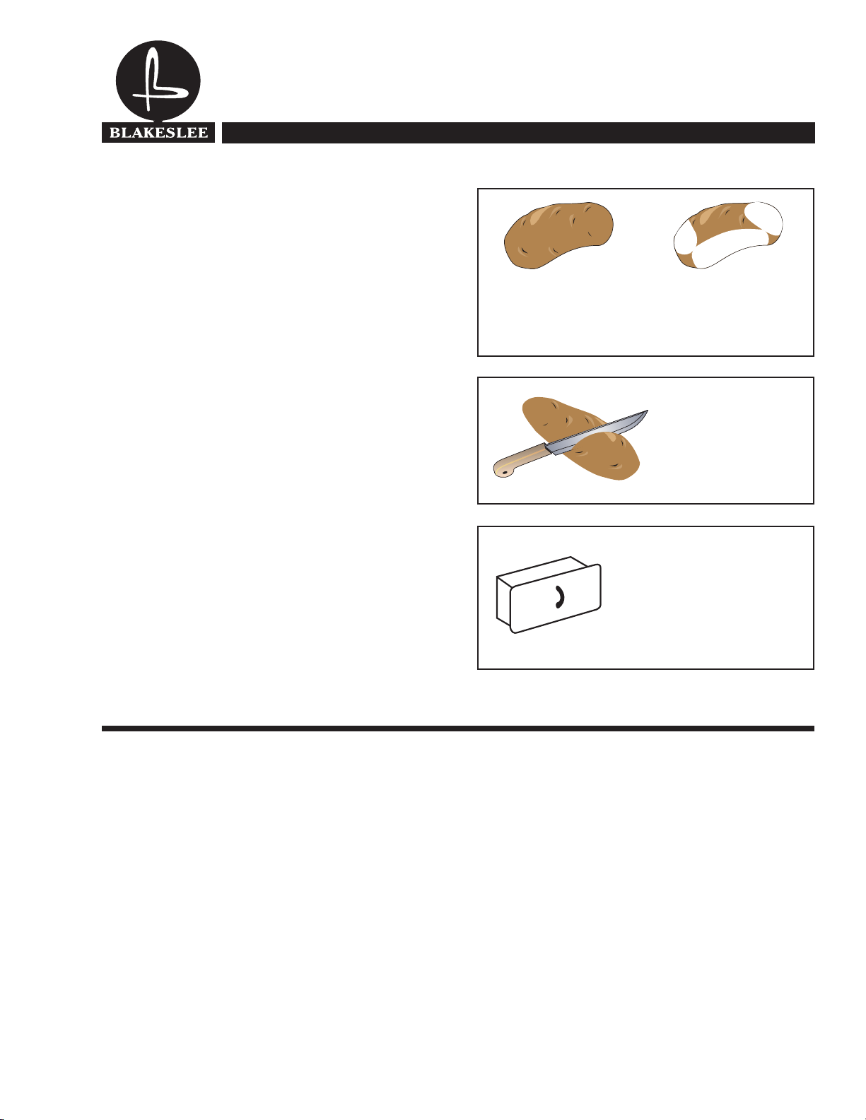
For best peeling results, do not overload peeler.
Overloading prevents proper tumbling of potatoes,
causing uneven peeling.
Cut long Idaho’s in half
for more efficient
peeling.
To discharge the peeled potatoes, merely open the door
of the peeling chamber and the peeled potatoes will
automatically be thrown out. After the peeled potatoes
have been discharged, turn off the water and the motor.
Do not peel the eyes out of the potatoes as it is much
more economical to trim out the eyes by hand after
peeling. When peeling large quantities of potatoes,
empty the peel trap strainer basket frequently.
CLEANING
When all of the potatoes and vegetables have been
peeled, and before the inside of the peeler has had
time to dry, remove the cover and the peeling disc
and hose out the inside of the peeler. Always
remember to empty and clean the peel trap strainer
basket.
All Stainless Steel Peel
Trap: prevents clogging of
drain system and is easliy
cleaned.
CAUTION: Be sure motor is connected so peeling
disc operates in clockwise direction.
This is very important as if motor is
running backwards,
fly off when potatoes are being peeled.
peeler
cover will
3
Page 6
Illustrated Parts Manual
Models S-15, XC-15, XC-30, XC-60
Potato and Vegetable Peelers
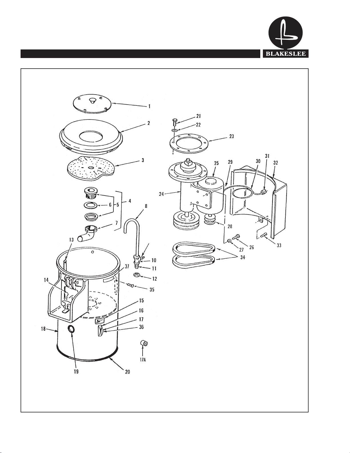
Figure 1. Model S-15 Peeler
4
Page 7

Illustrated Parts Manual
Models S-15, XC-15, XC-30, XC-60
Potato and Vegetable Peelers
Figure 1. Model S-15 Peeler
Index No. Part No. Description No. Reqd.
1 P2-5100 SPLASH COVER 1
2 P2-5163 HOPPER, Plastic 1
3 P4-5270 PEEL, DISC 1
4 P2-5144 DRAIN ASSEMBLY, (Consists of items 5, 6, &, 7) 1
5 P1-5291 DRAIN CUP w/Flanged Locknut 1
6 P1-5292 GASKET 1
7 P1-5295 WASTE TUBE w/Locknut and Rubber Washer 1
8 P1-5066 SPRAY PIPE 1
9 P1-17238 NIPPLE, Dixon Style 3500 1
10 P1-17236 TEE, ¼ X 3/8″ Female 1
11 P1-5210 STUD, ½ X 3″ 1
12 WO-14192 LOCKNUT, ½ X 13 Hex Jam Nut, Cadm Plated 1
13 P1-5272 LOBE, Peeler 2
14 P4-5258 DOOR ASSEMBLY, (See Fig. 3 for Detail Parts) 1
15 P1-5052 PLATE, Data 1
16 P1-5096 PLATE, Switch Cover 1
17 P1-15260 SWITCH, Toggle, 1 PIL, Flush 1
17 P1-17203 SWITCH, Toggle, 3 PIL, Flush 1
17A P-2-05108 SWITCH, Timing 1ph. Only (opt.)
18 P4-5212 HOUSING, Upper w/Chute Casting 1
19 P1-17246 RUBBER GROMMET 1
20 P1-17247 GASKET, Channel 1
21 W1-8148 CAPSCREW, 3/8 X ¾″ lg., S/S 8
22 W1-5587 WASHER, Plain 3/8”, S/S 8
23 P2-5010 GASKET 1
24 P4-5220 BEARING COLUMN ASSEMBLY, Complete (See Fig. 4 for detail parts) 1
25 P1-5280 MOTOR, 1/3 H.P., 1 PH., 115/230V 1
25 P1-5281 MOTOR, 1/3 H.P., 3 PH., 220V 1
26 W1-7111 CAPSCREW, 5/16 X ¾″ lg. Hex Hd. 4
27 W-1-5587 LOCKWASHER, 5/16”, S/S 4
28 P1-5111 SHEAVE (2 Groove) 1
29 M1-15388 CONNECTOR, 3/8″ 90° (Not Illustrated) 1
30 P1-17214 CORD, No. 14 AWG, 3 Wire Cond. 1 PH. 6 Ft.
30 M1-15369 CORD, No. 14 AWG, 4 Wire Cond. 3 PH. 6 Ft.
5
Page 8

Illustrated Parts Manual
Models S-15, XC-15, XC-30, XC-60
Potato and Vegetable Peelers
Figure 1. Model S-15 Peeler (Continued)
6
Page 9

Illustrated Parts Manual
Models S-15, XC-15, XC-30, XC-60
Potato and Vegetable Peelers
Table 1. Model S-15 Peeler (Continued)
Index No. Part No. Description No. Reqd.
31 P1-17212 PLUG, Use with 3 Wire Cord, 120V, 1 PH., 15 Amp. 1
31A M1-15374 PLUG, Use with 3 Wire Cord, 250V, 1 PH., 15 Amp. 1
31B PO-17213 PLUG, Use with 4 Wire Cord, 208/240V, 3 PH., 20 Amp. 1
31C PO-95603 PLUG, Use with 4 Wire Cord, 480V, 3 PH., 20 Amp. 1
32 P4-5207 HOUSING, Motor Cover 1
33 W1-5987 SCREW, 10-24 X ½″ Pan Hd. 1
34 P1-15211 V-BELT, 31″ lg. 2
35 W1-10307 SCREW, 10/32 X 3/8″ lg., Rd Hd. Mach. 4
36 M1-95654 SWITCH GUARD 1
37 P1-95647 CAUTION LABEL 1
7
Page 10

Illustrated Parts Manual
Models S-15, XC-15, XC-30, XC-60
Potato and Vegetable Peelers
Figure 2. Models XC-15, XC-30 & XC-60 Peelers
8
Page 11

Illustrated Parts Manual
Models S-15, XC-15, XC-30, XC-60
Potato and Vegetable Peelers
Figure 2. Models XC-15, XC-30 & XC-60 Peelers
Index XC-15 XC-30 XC-60 Description Qty
No.
1 P2-5100 P2-5100 P2-5100 SPLASH COVER 1
2 P2-5163 P2-5164 P2-5164 HOPPER, Plastic 1
3 P4-5270 P4-5109 P4-5109 PEEL DISC 1
4 P1-5291 P1-5291 P1-5291 DRAIN PLUG, with flanged Locknut 1
5 P1-5292 P1-5292 P1-5292 GASKET 1
6 P1-5293 P1-5291 P1-5294 WASTER TUBE w/Locknut and Rubber Washer 1
7 P1-5066 P1-5066 P1-5066 SPRAY PIPE 1
8 P1-17238 P1-17238 P1-17238 NIPPLE, Dixon Style 3500 1
9 P1-17236 P1-17236 P1-17236 TEE, ¼ X 1/4″ Female 1
10 P1-5210 P1-5210 P1-5210 STUD, ½ X 3″ 1
11 WO-14192 WO-14192 WO-14192 LOCKNUT, ½ X 13 Hex Jam Nut, Cadm Plated 1
12 P1-5272 P1-5272 P1-5272 LOBE, Peeler 2
13 W1-10307 W1-10307 W1-10307 SCREW, 10/32 X 3/8″ lg. Rd Hd. Mach. (XC-60 Qty 6) 4
14 W1-11515 W1-11515 W1-11515 SCREW, 10/24 X 1/4″ lg. Rd Hd. Mach. 4
15 P1-17252 P1-17252 P1-17252 NUT, 10/24 Cap 4
16 P4-5258 P4-5025 P4-5025 CHUTE AND DOOR ASSEMBLY, 1
17 P4-5212 P4-5231 P4-5232 HOUSING, Upper w/Chute Casting 1
18 W1-7123 W1-7123 W1-7123 PLUG, Button 3
19 P1-5052 P1-5052 P1-5052 PLATE, Data 1
20 P1-5096 P1-5096 P1-5096 PLATE, Switch Cover 1
21 P1-15260 P1-15260 P1-15260 SWITCH, Toggle, 1 PIL, Flush 1
21 P1-17203 P1-17203 P1-17203 SWITCH, Toggle, 3 PIL, Flush 1
22 P-2-05108 P-2-05108 P-2-05108 SWITCH, Timing 1ph. Only (opt.) 1
23 P1-17250 P1-17250 P1-17250 ELECTRICAL BOX w/Cover 1
24 P4-5203 P1-5189 P1-5189 BASKET, Peel Trap 1
25 P3-5252 P3-5252 P2-5252 DEFLECTOR, Drain 1
26 W1-8148 W1-8148 W1-8148 CAPSCREW, 3/8 X ¾″ lg., S/S 8
(See Fig. 3 for detail parts)
27 W1-5587 W1-5587 W1-5587 WASHER, Plain 3/8″, S/S 8
28 P2-5010 P2-5010 P2-5010 GASKET 1
29 P4-5220 P4-5220 P4-5221 BEARING COLUMN ASSEMBLY, Complete 1
30 M1-15388 M1-15388 M1-15388 CONNECTOR, 3/8″, 90° (Not Illustrated) 1
31 P1-5280 P1-5282 P1-5281 MOTOR, 1/3 H.P., (XC-15), ¾ HP (XC-30), 1
31 P1-5281 P1-5283 P1-5285 MOTOR, 1/3 H.P., (XC-15), ¾ HP (XC-30), 1
32 W1-7111 W1-7111 W1-7111 CAPSCREW, 5/16 X ¾″ lg. Hex Hd. 4
(See Fig. 4 for detail parts)
1 HP (HC-60) 1 PH.
1 HP (HC-60) 3 PH.
9
Page 12

Illustrated Parts Manual
Models S-15, XC-15, XC-30, XC-60
Potato and Vegetable Peelers
Figure 2. Models XC-15, XC-30 & XC-60 Peelers (Continued)
10
Page 13

Illustrated Parts Manual
Models S-15, XC-15, XC-30, XC-60
Potato and Vegetable Peelers
Table 2. Models XC-15, XC-30 & XC-60 Peelers (Continued)
Index XC-15 XC-30 XC-60 Description Qty
No.
33 P1-17235 P1-17235 P1-17235 LOCKWASHER, 5/16” 4
34 - P1-5155 P1-5155 KEY, 3/16” X 2” lg. 1
35 P1-5111 P1-5007 P1-5131 SHEAVE 1
35A P1-95068 P1-95067 P1-95067 SHEAVE for 50 Cycle Motors Only 1
36 P1-17214 - - CORD, No. 14 AWG, 3 Wire Cond. 1 PH. (Opt XC-15) 6 Ft.
36A M1-15369 - - CORD, No. 14 AWG, 4 Wire Cond. 3 PH. (Opt XC-15) 6 Ft.
37 P1-17212 P1-17212 P1-17212 PLUG, Use with 3 Wire Cord, 120V, 1 PH., 15 Amp. 1
37A M1-15374 M1-15374 M1-15374 PLUG, Use with 3 Wire Cord, 250V, 1 PH., 15 Amp. 1
37B PO-17213 PO-17213 PO-17213 PLUG, Use with 4 Wire Cord, 208/240V, 60C, 3 PH., 20 Amp. 1
37C PO-95603 PO-95603 PO-95603 PLUG, Use with 4 Wire Cord, 480V, 60C, 3 PH., 20 Amp. 1
38 P4-5207 P4-5196 P4-5196 HOUSING, Motor Cover 1
39 W1-5987 W1-5987 W1-5987 SCREW, 10-24 X ½” Pan Hd. 1
40 P1-15211 P1-15211 - V-BELT, 31” lg. (XC-15 & XC-30) 2
40 - - W1-8888 V-BELT, 31” lg. (XC-60) 3
41 P4-5205 P4-5188 P4-5188 HOUSING, Lower Weldment 1
42 P2-17210 P2-17210 P2-17210 SIDING DOOR, S/S 1
43 P1-17228 P1-17228 P1-17228 Knob assembly, includes Item 43 Knob, 1
43A P1-17244 P1-17244 P1-17244 #8 LOCKWASHER 1
43B W1-7476 W1-7476 W1-7476 SCREW 1
44 P1-5199 P1-5199 P1-5199 CLAMP BAR 4
45 P4-5195 P4-5195 P4-5195 LEG, Aluminum 4
46 P1-17230 P1-17230 P1-17230 CAPSCREW, 3/8 X 1” lg. Hex Hd. 8
47 W1-7524 W1-7524 W1-7524 LOCKWASHER, 3/8”, Split 8
48 P1-17248 P1-17248 P1-17248 WASTE DRAIN 2” Brass 1
49 P1-5236 P1-5236 P1-5236 GASKET 1
50 P1-17249 P1-17249 P1-17249 LOCKNUT, Pipe, 2” 1
51 M1-95654 M1-95654 M1-95654 SWITCH GUARD 1
52 P1-95647 P1-95647 P1-95647 CAUTION LABEL 1
43A Lockwasher & 43B Screw
11
Page 14

Illustrated Parts Manual
Models S-15, XC-15, XC-30, XC-60
Potato and Vegetable Peelers
COMPLETE BEARING COLUMN
(Available As Assembly)
P4-5220: S-15, XC-15 & XC-30
Peelers with serial numbers up to 1AAA
P4-5221: XC-60
Figure 3.
Item No. Part No. Description No. Reqd.
1 P4-5222 BEARING COLUMN (S-15, XC-15 & XC-30) 1
1 P4-5224 BEARING COLUMN (XC-60) 1
2 P2-5225 DRIVE SHAFT, Peel Disc (S-15, XC-15 & XC-30) 1
2 P2-5227 DRIVE SHAFT, Peel Disc (XC-60) 1
3 P1-5177 DRIVING BLOCK 1
4 P1-17232 DRIV-LOK PIN ¼ x 2 1
5 P1-17222 BUSHING, Plain Used up to 6-1-85 1
5A 70170 BALL Bearing, Used after 6/1/85
6 P1-17225 BEARING Roller Cone 1
7 P1-17224 BEARING, Cup 1
8 P1-17233 PIPE PLUG, 1/8-27 N.P.T. 1
9 P1-5253 SPACER 1
10 P1-5274 OIL SEAL 1
11 P1-17229 PULLEY 2-Groove (S-15, SC-15 & XC-30) 1
11 P3-5135 PULLEY 3-Groove (XC-60) 1
12 P1-17242 KEY, ¼″ SQ. x 1-1/2″ lg. 1
13 W1-7117 SET SCREW, 5/16 x 3/8″ lg. Cup Ft. 1
12
Page 15

Illustrated Parts Manual
Models S-15, XC-15, XC-30, XC-60
Potato and Vegetable Peelers
COMPLETE BEARING COLUMN
(Available As Assembly)
P4-5220: S-15, XC-15 & XC-30
Used on machines with serial number suffix A A B and up
P4-5221: XC-60
Figure 4.
Item No. Part No. Description No. Reqd.
1 5222 BEARING COLUMN (S-15, XC-15 & XC-30) 1
1 5224 BEARING COLUMN (XC-60) 1
2 73195 DRIVE SHAFT (S-15, XC-15 & XC-30) 1
2 73196 DRIVE SHAFT (XC-60) 1
3 73197 DRIVE BLOCK 1
4 17232 DRIV-LOK PIN 1
5 70170 BALL BEARING 1
6 17225 TIMKEN CONE 1
7 17224 TIMKEN CUP 1
8 2255 SHAFT SEAL ASSY 1
9 3488 RETAINING RING 1
10 73203 RETAINING RING 1
11 17229 PULLEY (S-15, SC-15 & XC-30) 1
11 5135 PULLEY (XC-60) 1
12 17242 KEY 1
13 7117 SET SCREW 1
14 73198 SPACER
1
13
Page 16

BLAKESLEE
Illustrated Parts Manual
Models S-15, XC-15, XC-30, XC-60
Potato and Vegetable Peelers.
1
5
6
3
2
Used on machines with serial number suffix BAB and up
7 9
4
8
COMPLETE BEARING COLUMN ASS’Y
05221: S-15, XC-15 & XC-30
05221: XC-60
Figure 5
Item No. Part No. Description No. Reqd
1 77591 BEARING COLUMN 1
2 77594 DRIVE SHAFT (S-15, XC-15 & XC-30) 1
2 77593 DRIVE SHAFT (XC-60) 1
3 77592 DRIVE BLOCK 1
4 17229 PULLEY(S-15, XC-15 & XC-30) 1
4 05135 PULLEY (XC-60) 1
5 77595 BALL BEARING 2
6 77596 THRUST WASHER 1
7 70170 BALL BEARING 1
8 17242 .25 SQ. KEY STOCK 1
9 73203 RETAINING RING 1
10 07117 5/16-18 3/8 CUP POINT SET SCREW 1
14
10 10
Page 17

Illustrated Parts Manual
15
Figure 6.
Models S-15, XC-15, XC-30, XC-60
Potato and Vegetable Peelers
DOOR ASSEMBLY
(Not Available as Assembly)
Figure 5.
Item No. Part No. Description No. Reqd.
1 P4-5014 DOOR, Peeler 1
2 P1-5036 SPRING 1
3 P1-5254 PIN, Hinge 1
4 P1-5035 PLUNGER 1
5 P1-5030 LATCH JAM 1
6 P1-5037 HANDLE, Latch 1
7 W-1-7598 LOCKWASHER, 5/15 S/S 1
8 W-1-8138 CAP NUT, Brass, 5/16-18 S/S 1
9 P1-17231 DRIV-LOK PIN, S/S 1
10 P1-5269 BALL PLUNGER 1
11 W1-8132 JAM NUT, 10/32 1
12 P-4-5024 CHUTE CASTING (S-15, XC-15) 1
12A P-4-5051 CHUTE CASTING (XC-30, XC-60) 1
14
Page 18

Illustrated Parts Manual
16
Models S-15, XC-15, XC-30, XC-60
Potato and Vegetable Peelers
Troubleshooting Chart
TYPE OF TROUBLE REASON CORRECTIVE MEASURE
Peeler will not start Main Fuse or Circuit Breaker Change fuses or reset circuit breaker
Wire loose or broken Overload switch tripped Push reset button. Visually check all
connections, controls and motor. Check
switch.
Motor runs but peeler disc
does not run
Peeler runs hot or smokes Improper voltage for motor or motor defective.
Peeler makes noise when
running
Peeler leaks water at the
center bearing
Peeler won' t peel potatoes Worn peeler abrasive disc
Belt broken or slipping Adjust belt tension or replace broken
Motor overloading, thus overheating
Bearing column tight not free running
Worn out bearings Field replacement of bearings is
Defective seal Replace seal (refer to pages 7 and 8 for
belts.
Check incoming voltage and motor.
Check amperage draw.
Grease by removing plugs at lower
bearings using Elimite grease gun and
Shell Darlina 2 grease or equivalent.
Some units may not have plugs. Unit
must then be disassembled and the
grease manually applied.
extremely difficult. It is strongly suggested
to replace the entire bearing column
assembly when the bearings require
replacement. Refer to pages 12 or 13 for
part number.
exact type).
Replace abrasive disc
P4-5270 (XC-15)
P4-5109 (XC-30, XC-60)
Peeler overloaded
Flat spots on Idaho potatoes Potatoes are too long Cut Idaho potatoes in half before inserting
Water splashes out when
peeling potatoes
Water leaking on floor Peel trap basket full of peelings
Too much water pressure
or
Splash cover missing
Lower drain plugged up
Use proper amount of potatoes for your
type of peeler (See Owners Manual).
in machine.
Turn water valve down to regulate.
Replace splash cover P/N P2-5100.
Empty peel trap basket.
Clean or rod out drain.
15
Page 19

PARTS & SERVICE USA
Blakeslee Authorized Parts & service Distributors and Preferred Service Agents are the focal point for service and are responsible for all warranty/repair
work and for maintaining a complete stock of replacement parts.
They have factory-trained servicemen and are kept informed by the factory on the latest servicing procedures.
To receive service and/or parts, call the Blakeslee Distributor nearest you. If you happen to be in an area not covered by a distributor, phone the Blakeslee
Service Department in Chicago at 708-656-0660 for the name and location of one of over 300 strategically-located Blakeslee Authorized Service Agencies,
which is nearest you.
ALABAMA FLORIDA (Cont.) LOUISIANNA NEW YORK TENNESSEE
Jones McLeod Appliance Co. Nass Service Co. Inc. Chandler’s Parts & Service Acme American Repairs Inc. A-Tech Inc
1616 Seventh Ave. North 1108 S. Woods Ave. 11656 Darryl Drive 99 Scott Ave. 424 Sixth Avenue South
Birmingham, AL 35203 Orlando, FL 32805 Baton Rouge, LA 70815 Brooklyn, NY 112237 Nashville, TN 37203
205-251-0159 407-425-2681 225-272-6620 718-456-6544 615-255-2002
ARIZONA GEORGIA MARYLAND
3138 Oneida Street 1209 S. Watkins
Byassee Equipment TWC Electric Motor Repair CO. Sauquoit (Utica), NY 13456 Chattanooga, TN 37404
1939 E. Washington 5080 Highlands Pkwy S. A150 700 East 25
Phoenix, AZ 85034 Smyrna, GA 20082 Baltimore, MD 21218
602-252-0402 770-438-9797 410-467-8080
3717 Cherry Road
ARKANSAS HAWAII MASSACHUSETTS
1020 Tuckaseegee Road 901-366-4587
Bromley Parts & Service Commercial Appliance Ace Service Co. Inc. Charlotte, NC 28208
10th & Ringo Street Parts & Service Co. 95 Hampton Ave. 704/377-4501
Little Rock, AR 72202 1623 Democratic St. Needham (Boston), MA 02194
501-374-0281 Honolulu, HI 96819 617-449-4220
808-841-4545 1377 N. Bravos
CALIFORNIA
Acme Pacific Repairs, Inc. E & G Appliance Service Co. Akron, OH 44314
1347 Fulton Place Boise Appliance 1435 Lawndale Ave. 330/753-6635 Kenco Service
Fremont, CA 94539 1503 Main Street Detroit, MI 48209 26 Lyerly – Suite 1
510-252-2070 Boise, ID 83702 313-842-2252 Commercial Parts & Service Houston, TX 77022
208-343-0102 6940 Plainfield Road 713-691-2935
Barker’s Food Machinery Ser. Midwest Food Equipment Serv. Cincinnati, OH 45236
5367 Second Street
Irwindale, CA 91706 Grandville, MI 49418 2120 Solana
626-960-9390 Eichenauer Food Equipment 616-261-2000 Electrical Appliance Repair Fort Worth, TX 76117
130 S. Oakland Ave. 5805 Valley Belt Road 817-831-0381
Chapman Appliance Service Decatur, IL 62522
1784 San Diego Ave. 217-429-4229 216-459-8700
San Diego, CA 92126 GCS
619-298-7106 General Parts Inc 2857 Louisiana Ave. North
248 James Street Minneapolis, MN 55427 Equipment Service
Sterling Service Bensenville, IL 60106 763-546-4221 Krueger Electric Service Inc. 6182 South Stratler
644 W. Hawthorn Street 630-595-3300 100 N.E. 24
Glendale, CA
818-243-1234 Rescor 405-528-8883
5344 East Ave. Camp Service & Parts Inc.
COLORADO
708-352-3155 Jackson MS 39201 Authorized Appliance
Metro Appliance Service 601-353-9700 Ron’s Service Inc. 74
1640 S. Broadway
Denver, CO 80210
303-778-1126 GCS 503-624-0890
5310 East 25
CONNECTICUT
317-545-965 5 St. Louis, MO 63105 Daubers Inc.
A-Tech Service, Inc. 314-535-2222 American Kitchen Mach. Corp. 7645 Dynatech Court
161 Sanrico Drive
Manchester, CT 06040
860-649-6627 Goodwin-Tucker 215-627-7760
2900 Delaware Ave Goodwin-Tucker Group
DISTRICT OF COLUMBIA
515-262-9308 Omaha, NE 68124 210 Vista Park Dr. Walsh Equipment Repair
Electric Motor Repair 402-397-2880 Pittsburgh, PA 15205 1519 128
700 East 25th Street
Baltimore, MD 21218
410-467-8080 General Parts, Inc. K & D Parts
1101 E. 13
FLORIDA
816-421-5400 Las Vegas, NV 89103 717-236-9039 Authorized Factory Service
Commercial Appliance Service 702-736-0006 Edens Fork Exit I 77
8416 Laurel Fair Circle
Tampa, FL 33610
813-663-0313 GCS Whaley Foodservice Repairs
4204 S. Brook Street R & B Service 137 Cedar Road
Dade Restaurant Repair Louisville, KY 40214 4412 Towner N.E. Lexington, SC 29171
2001 W. 27
Hihleah, FL 33010 505-889-4090 800-877-2662 W223 N. 735 Saratoga Dr.
305-887-0783 GCS Waukesha, WI 53186
533 A Codell Drive 262-650-6666
GCS Lexington, KY
3373 Northwest 168
Miami, FL 33056
305-623-7001
th
Street 502-367-1788 Albuquerque, NM 87110 803-996-9920 General Parts Inc.
th
Street 859-269-7484
IDAHO
ILLINOIS
Countryside, IL 60525 328 B Oakdale Street
INDIANA
th
Indianapolis, IN 46218 2728 Locust Street
Street Kaemmerlen Parts & Service
IOWA
Des Moines, IA 50137 7535 D Street GCS
KANSAS
th
Kansas City, MO 64101 4480 Aldebaran Ave. Harrisburg, PA 17103
Street Burney’s Commercial Service 1833-41 N. Cameron Street
KENTUCKY
MICHIGAN
1169 W. Waterloo Road 210-735-2811
3055 Dixie 513-984-1900 Stove Parts Supply Co.
MINNESOTA
MISSISSIPPI
16364 S.W. 72nd Ave. Rutland, VT 05701
MISSOURI
204 Quarry Street Springfield, VA 22153
NEBRASKA
412-787-1970 Bellevue, WA 98005
NEVADA
NEW MEXICO
th
Street 315/737-9401 423-624-3381
Duffys Rest. Equip. Service FESCO
NORTH CAROLINA
GCS
Authorized Appliance Service Memphis, TN 38118
TEXAS
OHIO
Commercial Kitchen Repair
Akron Restaurant Equipment San Antonio, TX 78207
Cleveland, OH 44131
OKLAHOMA
th
Oklahoma City, OK 73105 801-263-3221
Street Murray, UT 84107
OREGON
UTAH
LaMonicas Restaurant
VERMONT
th
River Street
Portland, OR 97224 802-775-5588
PENNSYLVANIA
VIRGINIA
Philadelphia, PA 19106 703-866-3600
WASHINGTON
th
Place N.E.
425-462-1645
WEST VIRGINIA
SOUTH CAROLINA
304-344-8225
Charleston, WV 53186
WISCONSIN
Page 20

PARTS & SERVICE Canada
ALBERTA MANITOBA NOVA SCOTIA Continued
Great West Comm. Kit. Rep. Grand Valley Mechanical Buddens Appliance Service Blanchfield Comm. Kit. Serv. Electro Ref. Service Ent.
5664 Burleigh Cresc. S.E. 360 Park Avenue E., 164 Nichols Avenue 770 Industrial Ave., Unit 13 161 Pere Divet
Calgary, AB T2H 1Z8 Brandon, MB R7A 6N2 Kentville, NS B4N 2H6 Ottawa, ON K1G 4H3 Sept-lles, QC G4R 3P8
Tel: 403-276-7832 Tel: 204-728-3898 Tel: 902-678-7895 Tel: 613-737-6632 Tel: 418-962-9186
L.D.I. Technical Services Commercial Kitchen Equip. J.R. Mahone y Ltd. McNabb Appliances Kitchen Equipment Services
4 – 3600 21
Calgary, AB T2E 6V6 Winnipeg, MB R3G 2T6 Sydney, NS B1L 1C5 Peterborough, ON K9H 1T6 Sherbrooke, QC J1H 1R9
Tel: 403-299-9591 Tel: 204-586-8273 Tel: 902-564-8775 Tel: 705-743-5350 Tel: 819-821-2153
Res Tech Service Ltd. Syd Tech Appliances Erlmar Plumbing Ltd. Choquette CKS
North Star Repair 593 Sherburne Street Box 1907 795 Batory Avenue 900 Pierre Bertrand, #220
11518 119
Edmonton, AB T5G 2X7 Tel: 204-228-5399 Tel: 902-561-0156 Tel: 905-420-5252
Tel: 780-453-6213
Robertshaw Refrigeration
P.O. Box 840 D & L Electric Tel: 902-897-0479 St. Catharines’s ON L2R 3X8 Comfort Mechanical
Cold Lake, AB T9M 1P2 83 Sister Green Road
Tel: 780-594-3488 Campbellton, NB E3N 3Y5
Tel: 506-753-5076
Re-Nu Mechanical Ltd. OFS Restaurant Appl. Serv. 116 Talford Street
1710 Bay F – 31
Lethbridge, AB T1H 5H1 88 Beaverbrook Street Barrie, ON L4M 4S4 Tel: 519-332-1770 1327 Hamilton Street
Tel: 403-327-7368 Moncton, NB E1C 8H7 Tel: 705-728-5289 Regina, SK S4R 2B6
Tel: 506-857-2232 Sault Rapid Repair Tel: 306-525-1979
Medicine Hat Refrigeration ChemMark 1496 Wellington St. E.
666 17
Medicine Hat, AB T1A 4X7 122 Driscoll Avenue Chalk River, ON K0J 1J0 Tel: 705-759-3311 410 Lauriston Street
Satellite Mechanical Ltd. Tel: 506-855-4228 Tisdale Plumbing & Heating Tel: 306-653-2772
#1 – 5571 45
Red Deer, AB T4N 1L2 I Line Electric Ltd. R.R. #5, 823974 Massie Rd.
Tel: 403-343-6122 280 Dalton Avenue Chatsworth, ON N0H 1G0 Tel: 705-235-4045 Oscar’s Electric
Miramichi, NB E1V 3N9 Tel: 519-794-3633 310 Alexander St.
BRITISH COLUMBIA
Key Food Equip. Services Fundy Gas & Electric 39 Regal Road Chelmsford, ON P0M 1L0
180 – 3700 North Fraser 45 Glen Road Guelph, ON N1K 1B6 Tel: 705-671-6477 Yukon Appliance Sales & Serv.
Burnaby, BC V5J 5H4 Saint John, NB E2H 2C9 Tel: 519-836-1090 9041 Quartz Road
Tel: 604-433-4484 Jemm Service White Horse, YK 1A 4Z5 Y
Marsh & Sons Ventures
10411 – 95
Fort St. John, BC V1J 5Z4 14 Cooks Avenue Tel: 905-527-2525
Tel: 250-787-9733 Cornerbrook, NF A2H 1P1 R.G. Henderson & Son Ltd.
Tel: 709-634-7588 J.I.K.S. Ind. Kitchen Serv. 100 Thorncliff Park Dr.
J.D. Appliance Repairs 42 Groff Place, #4 Toronto, ON M4H 1G9
1965 Moss Crt. Domestic Service Centre Kitchener, ON N2E 2L6 Tel: 416-423-4357
Kelowna, BC V1Y 9L3 27 McCurdy Drive,
Tel: 250-860-5057 Gander, NF A1V 1W5
Jemco Food Equip. Service 660A Justus Drive Waites Enterprises
7431 Industrial Road Harold Snow & Son Ltd. Kingston, ON K7M 4H4 626 South Drive
Lantzville, BC V0R 2H0 451 Kenmount Road Tel: 613-384-1718 Summerside, PEI C1N 3Z7
Tel: 250-390-3244 St-John’s, NF A1B 3P9 Tel: 902-436-7509
Tel: 709-754-0330 A-1 Plumbing & Heating
Sheridan Appliances P.O. Box 414
764 Chaparral Place
Kamloops, BC V2C 5W4
Tel: 250-314-1722 Jerome Cameron 8487 19
R.R. #5, Salt Springs Action Rest. & Serv. Equip. Montreal, QC H1Z 4J2
Mark’s Rest. Services Antigonish, NS B2G 2L3 151 Bentley Street, #9 Tel: 514-723-5000
515 Dupplin Road, #3 Tel: 902-863-4528 Markham, ON L3R 3L1
Victoria, BC V8Z 1C2 Tel: 905-475-1499 L. Chasse Inc.
Tel: 250-475-6275 Harry Rhyno Refrigeration 448 Richelieu
233 North Street Stell Mechanical Pointe au Pic, QC G5M 1C9
Key Food Services Bridgewater, Lun. Co. NS 25 Iron Street Tel: 418-723-9100
2740 Bridge St., #105 B4A 2V7 Etobicoke, ON M9W 5E3
Victoria, BC V8T 5C5 Tel: 902-543-4737 Tel: 905-569-8270 Majella Vaillancourt
Tel: 250-920-4888 82 St. Cyrille
Walker’s Electric Repco Restaurant Equip.
Triumph Food Equip. Service 2608 Windsor Street 9208 Lundy’s Lane Tel: 418-862-2503
4671 Slocan Street Halifax, NS B3K 5C8 Niagara Falls, ON L2E 6S4
Vancouver, BC V5R 1Z8 Tel: 902-454-0291 Tel: 905-358-9071
Tel: 604-454-9326
st
St. N.E. 731 Wall Street 1810 Kings Road 370 Burnham Street 893 King Street W.
th
Street Winnipeg, MB R3G 2K8 Sydney, NS B1P 6W4 Pickering, ON L1W 2W5 Ville Vanier, QC G M 3K2 1
st
St. N. Electrical & Refrigeration Serv. 16 Lennox Dr., R.R. #2 Sarnia, ON N7T 7J2 Northcote Sales & Serv. Co.
th
Street S.W. EMR 52 Highway 17, P.O. Box 371
th
Street
th
Avenue Bob’s Electric Hamilton, ON L8L 3C4 Tel: 807-623-7851
NEW BRUNSWICK
Moncton, NB E1E 3R8 Tel: 613-584-2988 Saskatoon, SK S7K 0R5
Tel: 506-622-2214 Sudbury Rapid Service Whitehorse, YK Y1A 2L6
G.R. Garrity 23 Main Street Tel: 867-667-2330
NEWFOUNDLAND
Tel: 709-256-7738 R.G. Henderson & Son Ltd.
NOVA SCOTIA
P.O. Box 83 Tel: 519-748-5361
Fundy Appliance Service Sure-Fix Food Equip. Serv.
Truro, NS B2N 5B3 52 Vine Street S.
ONTARIO
Kitchenworks Rest. Equip. Sup 40 Golden Avenue
Barbers Rest. Eq. & Repairs 1211 Ford Street
927 Barton Street E. Thunder Bay, ON P3A 4R8
Ilderton, ON N0M 2A0
Tel: 519-455-6559 Choquette CKS
ONTARIO
Tel: 905-685-0480 1355 11th Avenue
Regina, SK S4P 0G8
W.J. Barnes & Son Tel: 306-352-0544
Sault Ste. Marie, ON P6A 2R1
South Porcupine, ON P0N 1H0
P.E.I.
QUEBEC
Riviere de Loup, QC G5R 2G8
Continued
th
Avenue
QUEBEC
Tel: 418-681-3944
SASKATCHEWAN
Evan’s Restaurant Serv.
YUKON
Tel: 867-668-4844
Puerto Rico
Gas Repair Equipment
7 St. N.E. #322 Puerto Nuevo
San Juan, PR 00920
787-749-8044
Page 21

Notes
Page 22

Illustrated Parts Manual
g
Models S-15, XC-15, XC-30, XC-60
Potato and Ve
etable Peelers
BLAKESLEE
Date of Installation
Serial
No.
Model
No.
Your new Blakeslee peeler is warranted for one year from date of installation shown above
against defective materials and workmanship. If any defects are found within the warranty
period; parts, and labor involved with their replacement will be covered free of charge.
Service must be performed by a Blakeslee authorized service agency. All labor to be
performed during regular working hours. Overtime premium will be charged to the
customer. All warranty parts are shipped by surface transportation. If other means of
transportation is requested the customer is required to pay the premium. This warranty
does not apply to damages resulting from errors in installation on the part of other
contractors, nor does it apply to machines which have been subject to accident, misuse, or
abuse. It is understood that Blakeslee’s warranty obligation with respect to machines
located outside of the United States or located in the state of Alaska is limited to the
furnishing of replacement parts only. In the state of Hawaii, repair labor is provided free of
charge; travel time and expenses paid by the customer. On the island of Oahu, repair labor,
travel time and expenses are provided free of charge. This is the entire and only warranty
of Blakeslee. We neither assume nor authorize anyone else to assume for us any other
obligation or liability in connection with Blakeslee Machines.
Limited Warranty
● In no case can this warranty exceed eighteen (18) months from the date of shipment from
our plant at Chicago, Illinois
 Loading...