

Page 1
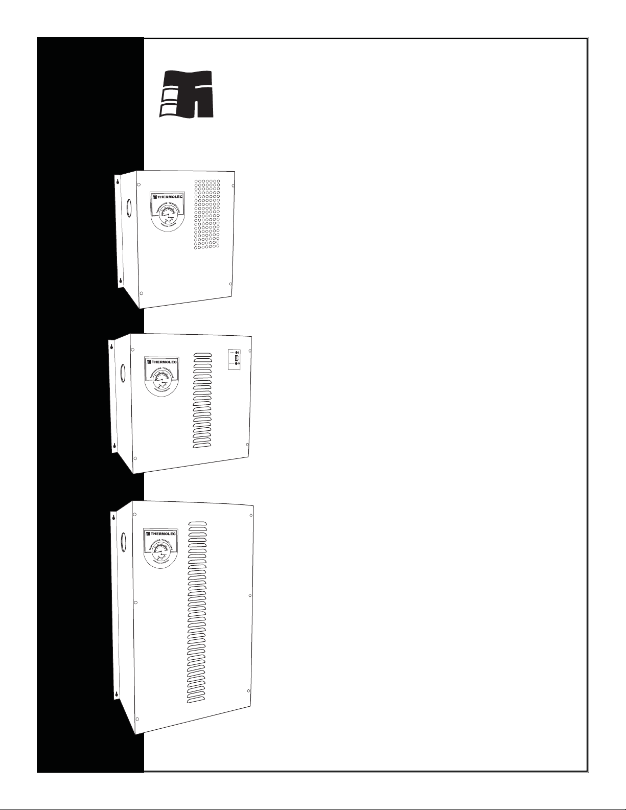
THERMOLEC
Installation
Instructions
for
Electric
Boilers
(CANADA)
December 2011
VERSION 11
Page 2

Page 3
Installation Guidelines for Thermolec Electric Boilers Model B
1 Important
1.1 These instructions should be used as a general guide only. Electrical Code and local utility requirements must
be followed and take precedence over these instructions.
1.2 Thermolec electric boilers are manufactured with quality components for maximum life, durability and
minimum service. To ensure a satisfactory installation it is imperative that you read these instructions
carefully before installing and operating the heating system.
Failure to do so may result in breach of warranty.
2 Unpacking
2.1 Inspect the unit and check whether there are missing parts.
2.2 Report any damage or claims to the carrier immediately.
2.3 For all returns to be accepted they must be authorized by the manufacturer.
3 Location and dimensions
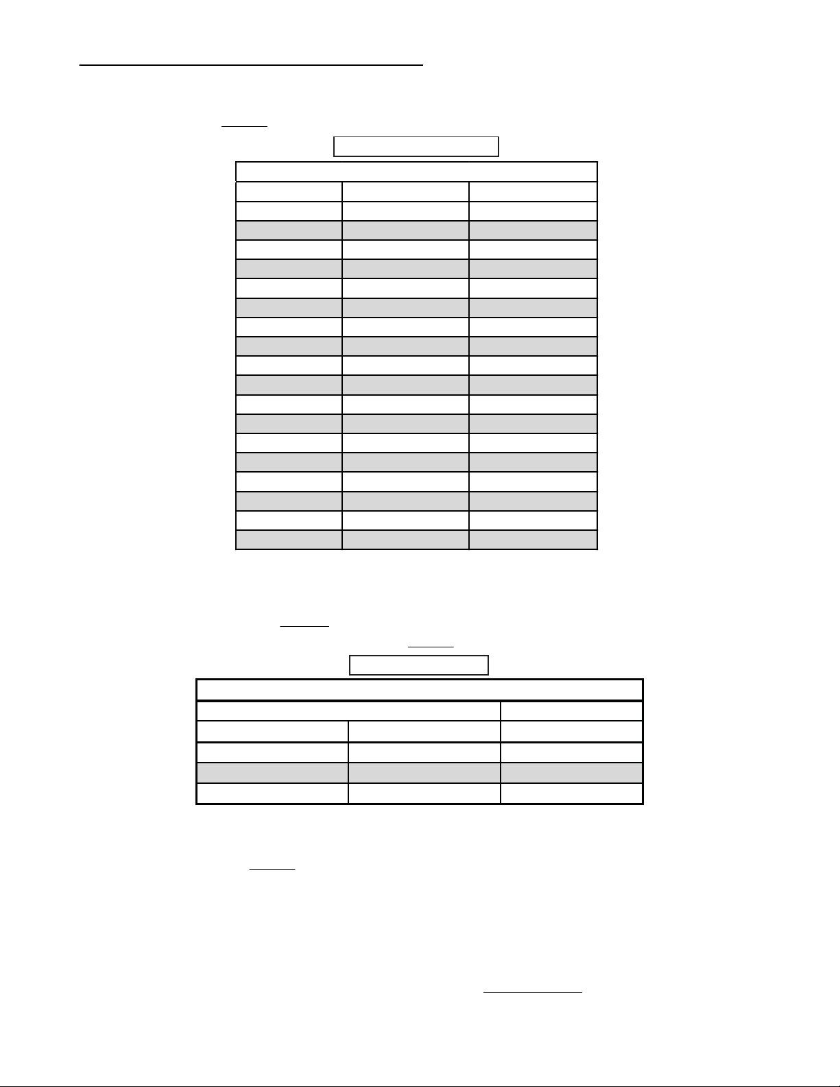
3.1 These boilers are designed for wall mounting. Please see Table 1 below for overall dimensions.
Table 1 also gives the minimum clearances to combustible material as well as recommended distances for
ease of service (e.g. replacement of tubular elements).
Table 1
Dimensions and Clearances
Overall dimensions Clearances
Models Width Height Depth Front Back Top Right Others
Short Models
up to 23 kW 1ph
18" 18" 9-1/2"
36" 0" 12" 6"
up to 18 kW 3ph
Long Models
18" 28" 9-1/2"
36" 0" 24" 6" 12"
up to 40 kW
TMB
3.2 The boiler room should be well ventilated as to maintain the temperature below 25°C (77°F).
3.3 The unit must be mounted level on a vertical wall with the outlet tting on the left side of the unit.
13" 18" 9"
36" 0" 12" 6"
12"
12"
Page 1
Page 4
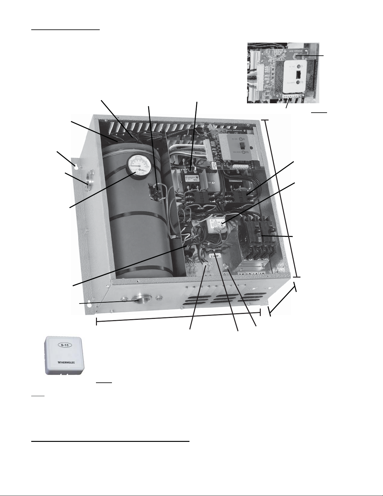
4 Components
Mono or Dual energy
controller
Adjustable
electronic
aquastat
(output
temperature)
Electronic
temperature
sensor
Mounting holes
Outlet 1-1/4’’ NPT
Temperature /
pressure
gauge
Incoloy elements Manual reset
thermal cut-out
Solid state relays
Thermostat terminals Fig. 2
Magnetic back-up contactor
Boiler control
transformer
18”
Circuit breaker (optional)
supplied when required
by N.E.C.
Pump relay
Inlet 1-1/4’’ NPT
Fig. 1
Outdoor reset sensor
Fig. 3
18”
Pump relay terminals
(dry contacts 10A)
Fuse and
fuse holder
Ground lug
Note : The model shown here is a typical Dual-Energy boiler 23kW / 240 Volts / 1phase.
5 Standard specifications for all models
Table 2 on the following page give specifications and current for the standard models.
9 1/2”
Page 2
Page 5
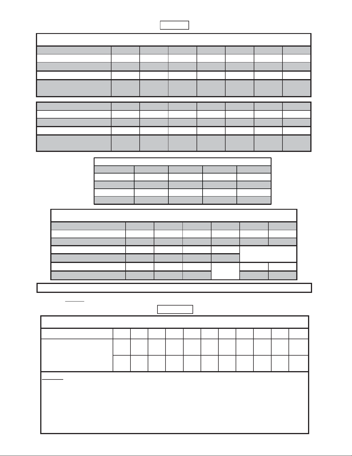
@
Table 2
(Canada)
(Canada)
Mono Models B-3TMB B-6TMB B-9TMB B-11TMB
kW 36911
BTU/H 10,236 20,472 30,708 37,532
Total Amps 12.5 25.0 37.5 45.8
Breaker size 1 x 20A 1 x 40A 1 x 50A 1 x 60A
TMB MONO Model Specifications @ 240V / 1ph (Canada)
Standard Model Specifications @ 240V / 1ph
Dual-Energy Models B-5 B-6 B-8 B-9 B-10 B-12 B-15
kW
BTU / H
Total Amps 20.83 25.00 33.33 37.50 41.67 47.92 62.50
No. Of Power Supplies 1 x 30A 1 x 30A 1 x 50A 1 x 50A 1 x 60A 1 x 60A 1 x 80A
(Amps Per Breaker)
Dual-Energy Models B-18 B-20 B-23 B-27 B-30 B-35 B-40
kW
BTU / H
Total Amps 75.00 83.37 95.83 112.50 125.00 145.83 166.67
No. Of Power Supplies 1 x 100A 1 x 125A 1 x 125A 2 x 80A 2 x 80A 2 x 100A 2 x 125A
(Amps Per Breaker)
56891011.515
17,060 20,472 27,296 30,708 34,120 39,238 51,180
18 20 23 27 30 35 40
61,416 68,240 78,476 92,124 102,360 119,420 136,480
Standard Model Specifications @ 3ph
Dual-Energy Models B-18 B-24 B-30 B-35 B-36 B-42
kW
BTU / H
Amps
208V / 3ph 48.00 66.69 83.37 96.00
Disconnect Switch 60A 100A 100A 100A
Amps @ 600V / 3ph 17.34 23.12 28.90 34.68 40.46
18 24 30 35 36 42
61,416 81,888 102,360 119,420 122,832 143,304
n/a
n/a
Disconnect Switch 30A 30A 30A 60A 60A
NOTE: Other models, voltages and capacities available upon request. Please contact the factory.
Please use Table 3 below to select the wire size for the power supply. (It is not mandatory to use copper wire).
Table 3
Cable Amps Capacity vs Wire Size (Copper)
Wire Size 12 10 864321000000
Amps @ 75°C (167°F)
Amps @ 90°C (194°F)
Notes :
1- This table should be used as a guide only. Always select the wire size according to the local
Electrical Code.
2- Always use wire suitable for 75°C (167°F) minimum, 300V or 600V as required.
20 30 45 65 85 100 115 130 150 175 200
20 30 45 65 85 105 120 140 155 185 210
3- All models with suffix "U" over 12 kW at 240V / 1ph require two feeders. Divide the total
Amps by 2 to select the proper wire size.
Page 3
Page 6
6 Water circulation and plumbing notes
Pipe Diameter
Imp. Gallons / min US Gallons / min (Type L Copper)
3.6 4.3 3/4"
8.4 10.1 1"
14.4 17.3 1-1/4"
Maximum Flow Rate
Maximum Flow Rate @ 15 psi
Capacity (kW) Imp. Gallons / min US Gallons / min
30.9 1.1
51.5 2.0
61.7 2.0
82.3 2.8
92.6 3.1
10 2.9 3.5
11 3.2 3.9
12 3.5 4.2
15 4.4 5.3
18 5.2 6.2
20 5.8 7.0
23 6.7 8.0
25 7.3 8.8
30 8.7 10.4
35 10.2 12.2
36 10.4 12.5
40 11.6 13.9
42 12.2 14.6
Recommended Water Flow Rate vs Capacity
6.1 The system is designed to operate with a maximum output temperature of 180°F or
lower and a temperature rise across the unit of 20°F or lower.
Please refer to Table 4 for the recommended flow rate versus the capacity of the boiler.
Table 4
6.2 In order to ensure an adequate flow rate :
6.21 Pressure loss (referred as "Head") caused by water friction in the system should not exceed the
capacity of the pump.
6.22 Please refer to Table 5 below to find the copper pipe diameter (type L) recommended to
accommodate the water flow found in Table 4 above.
Table 5
6.23 Elbows and valves will greatly add to the head loss in the system. An appropriate water flow rate
must be maintained to avoid tripping of the temperature limiter. Pipes with diameters larger than
specified in Table 5 will not help to increase water flow.
6.3 The installation must have a drain valve, an expansion tank, maintenance valves and an automatic
pressure reducing fill valve set at 15 PSI (104 kPA). A "T" fitting (1-1/4" NPT) must be installed at the
supply outlet of the unit. This "T" must be equipped with a reducing bushing 1-1/4" to 3/4" NPT, facing
upwards, to accept a 3/4" NPT pressure relief valve. This safety valve must be installed vertically. Except
for the pressure relief valve, the above plumbing supplies are not supplied with the unit. Please refer to
illustrations A, B and C at the end of this manual.
Page 4
Page 7
6.4 The automatic pressure relief valve supplied with the boiler is required to prevent dangerous pressure
build-ups in the system in case of system malfunction and may under certain conditions vent hot water.
Do not install the system where water could damage rugs, furniture, etc. When piping the relief valve to a
drain, check with local authority for recommended method of installation. Do not open or tamper with the
relief valve. If operated frequently or used to drain or flush the system, the valve could fail to seat properly
and thus leak.
Important safety notice : This safety valve is mandatory and must be installed as shown in the
illustrations A, B and C at the end of this manual. The omission of the safety valve installation will
create a very serious safety hazard and will void all warranties.
6.5 Automatic air vents should be installed at the highest point of the installation, ideally on all radiator units
for best results or at points where air could possibly be trapped in the system.
Caution : Make sure the system has been reasonably vented before starting the unit.
7 Mechanical installation
7.1 Mounting brackets are located on the sides of the boiler. Depending on the size of the unit, four or six
holes are provided. The unit may be attached directly to a combustible surface.
7.2 Use a circulator pump of appropriate capacity for the intended application. The pump should be placed as
close as possible to the boiler. Ensure that the water direction is correct. An arrow indicating the
circulation direction is generally visible on the pump casing.
7.3 Install inlet and outlet piping.
7.4 Install air vents, valves, the pressure relief valve supplied with the unit, expansion tank, etc.
7.5 When everything is finished, install the temperature / pressure gauge.
8 Electrical installation
8.1 Disconnect all power sources before opening the main panel and working within.
8.2 Read the nameplate and other markings carefully and wire strictly in accordance with the wiring diagram.
8.3 Wires and protective equipment must be sized according to the applicable Electrical Code.
8.4 Use only wires suitable for minimum 75°C (167°F).
8.5 Install the outdoor sensor on an exterior North wall and connect it with 18/2 wire to terminals
"OT / OT" on the electronic board (TH-600 series controller).
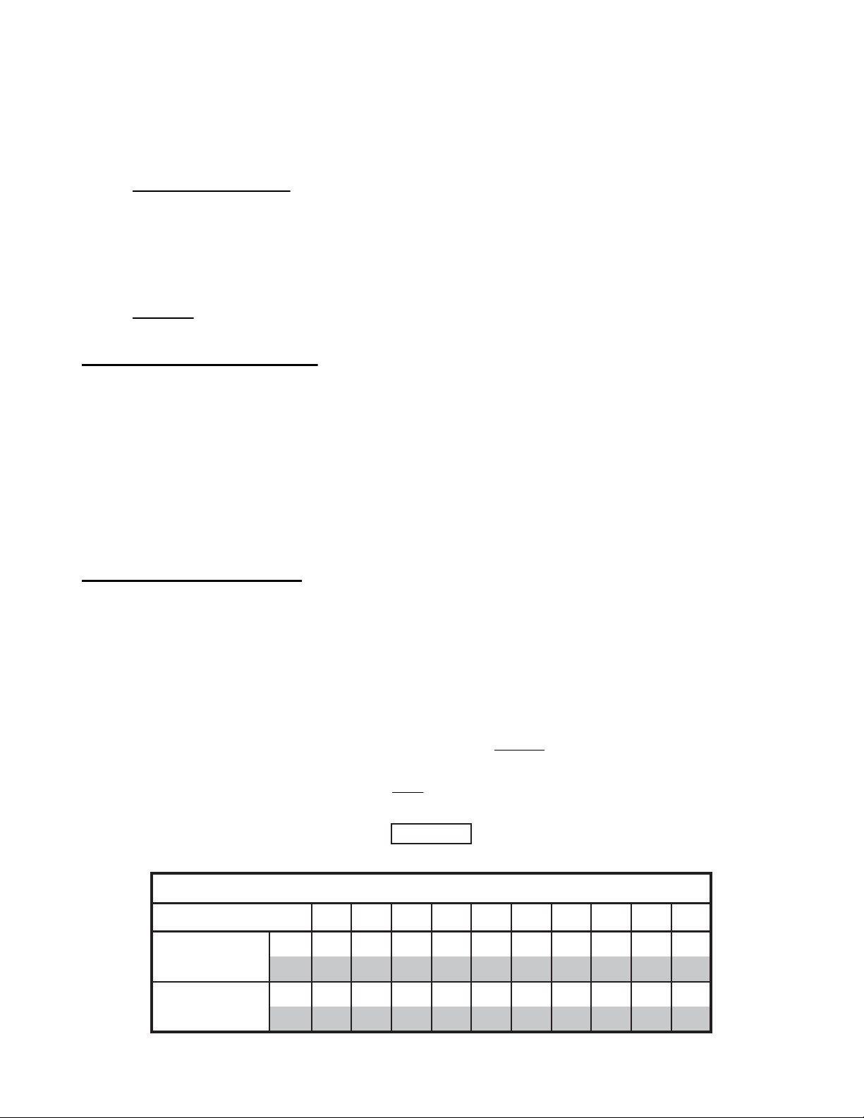
8.6 On the electronic aquastat (marked "WATER TEMPERATURE"), select the maximum water temperature
required (1-10) by the type of installation. Please see Table 6 below for the temperature obtained
according to the knob position. The minimum water temperature is reset automatically by the outdoor
sensor. Please see the variation graph in Fig 5.
Table 6
Water Temperature controlled by Electronic Aquastat
Set-point
Maximum
temperature
10987654321
°C
88 81 75 67 58 50 45 42 39 36
°F
190 178 167 153 137 122 113 107 102 97
Minimum
temperature
°C
48 48 48 45 40 38 34 31 29 28
°F
118 118 118 113 104 100 93 88 84 82
Page 5
Page 8

Electronic Aquastat
MAXIMUM
WATER TEMPERATURE
MINIMUM
WATER TEMPERATURE
°C°F-10
+14-5+230+32+5+41
+10
+50
Fig. 4 Fig. 5
8.7 The outdoor sensor will :
a) Maintain the selected maximum water temperature when the outdoor temperature is at -10°C
(+14° F) or colder.
b) Automatically and proportionally compensate by varying the water temperature between the
maximum and minimum when the outdoor temperature is between –10°C (+14°F) and +10°C
(+50°F).
c) Maintain the minimum water temperature when the outdoor temperature is between +10°C (+50°F)
and +20°C (+68°F).
d) Prevent boiler operation above +20°C (+68°F).
NOTE : If you choose not to use the outdoor sensor, don't connect it to the "OT / OT" terminals nor jumper
these terminals. You will not use this feature and the water will simply be maintained at the maximum
selected temperature.
8.8 Connect the thermostat or the zone valve end switch wires to "C" and "W1" terminals on the electronic
board.
8.9 Circulating Pump Control. The "P / P" terminals are connected to dry contacts of a relay (capacity up
to 1 HP) and are used to start the pump. This relay is switched ON with the first heating step and OFF
after the last one. A separate 120V / 1Ø service must be provided from the electrical panel to the boiler
for the pump. For Mono-Energy Boilers, refer to the wiring diagram. See the diagram for dual-energy as
the pump must also run when another source of heat is selected.
Follow the extra steps dedicated to a dual-energy installation in the start-up sequence.
8.10 Set the room thermostat heat anticipator (when available) to 0.2 Amperes.
8.11 If the system is used with Load Management control, connect the Utility signal to "S1 / S2" terminals.
A closed contact enables the boiler, an open contact disables the boiler.
8.12 The installation is now ready for start-up procedure and testing.
9 Start-up procedure and test sequence
Double check the following carefully :
9.1 All wiring and plumbing is complete.
9.2 Pipes have been cleaned, the system has been flushed and filled again.
9.3 Without powering the entire unit, install a jumper between the "P / P" terminals and switch the pump
breaker ON as to let the pump run alone. Verify that the pump is running freely and check for leaks. During
this test, a lot of bubbles will travel through the system and air will be eliminated by the automatic vents.
You can accelerate the process by purging the radiators manually. Shut off the pump breaker at the panel,
then remove the jumper between the "P / P" terminals.
9.4 The pressure in the system has been stabilized at approximately 15 PSI (104 kPA).
9.5 The entire system is now almost free of air.
9.6 The room thermostat anticipator (when available) has been set at 0.2 Amperes.
9.7 Switch the boiler breaker ON at the main panel.
Page 6
Page 9

9.8 Set the thermostat above the room temperature. The system should start.
9.9 Make sure the pump starts running as soon as the system starts.
9.10 Heating stages will be switched ON in sequence at 30 second intervals, confirmed by green lights on the
left hand side of the PC board on the TH600 or by red lights on the right hand side on the D22-B.
9.11 Wait for two minutes and measure the current drawn by the boiler and compare it with the one shown on
the nameplate.
9.12 When the required maximum water temperature selected on the aquastat (0-10) or controlled by the
outdoor sensor is reached, the electronic controller will modulate the boiler capacity to maintain the water
temperature, as long as the demand for heating is not satisfied. The bottom green light flashes
continuously on the TH600 or one of the red lights on the D22-B to indicate that the boiler is maintaining
the setpoint. When the room thermostat is satisfied, the heating stages will come OFF in sequence at 5
second intervals.
9.13 Set the room thermostat to the desired set point.
9.14 The boiler is now ready and functional.
Extra test steps for "Dual-Energy" installation.
9.15 Disconnect the room thermostat wires from the existing boiler and connect them to "C" and "W1" terminals
on the electronic board of the electric boiler.
9.16 Connect two (2) wires from "B / B" control terminals of the electronic board to the thermostat terminals of
the existing boiler.
9.17 Terminals "S1 / S2" on the electronic board should receive the utility Dual-Energy Signal wires.
9.18 Connect the pump terminals "P / P" in parallel to the existing thermostatic pump control as to allow the
operation of the pump in any of the "Dual-Energy" modes selected.
10 Test sequence for "Dual-Energy" systems
10.1 A "Dual-Energy" boiler is supplied with a three-position mode selector switch. Because of differences in
regional regulations, the electronic board has been factory set so as to allow the activation of the electric
mode depending on the unit destination. In the "Mazout / Oil" position the thermostat will call upon the
gas or oil boiler or furnace to maintain the house temperature at the desired level. The "Dual-Energy"
mode gives automatic control to the outdoor sensor or alternate switching signals from the local utility for
"Dual-Energy" control. When the "Dual-Energy" contacts are closed, the "Electric" mode is selected.
When these contacts are open, the "Mazout / Oil" mode is selected. If the "Electric" mode is manually
selected the controller allows only the electric mode operation. A green pilot light indicates the mode that
has been selected.
10.2 The positions of the manual selector are :
MAZOUT / OIL
BI-ÉNERGIE /
DUAL ENERGY
ÉLECTRIQUE /
ELECTRIC
Heating by means of original furnace (electric or mazout/oil).
Dual-Energy mode
(signal given by the
utility company)
Electric mode only
Fig. 6
Models with manually
selected Electric mode
available
Page 7
Page 10

10.3 Simulate a heating demand by setting the thermostat higher than the room temperature.
10.4 Switch the mode selector to position and check that the burner responds to the thermostat demand.
10.5 Switch the mode selector to the "Dual-Energy" position . Install a jumper between terminals "S1 / S2";
the electric mode is automatically selected. The pump will start and the heating stages will be switched
ON in sequence at 5 second intervals. Measure the current drawn by the boiler and compare it with the
one shown on the nameplate. If you remove the jumper from terminals "S1 / S2", the system should switch
back to the "Mazout / Oil" mode. Switch the mode selector to the "Electric" position . The controller
allows only electric heating even if the contact "S1 / S2" is open.
10.6 Switch the mode selector to the desired position and set the room thermostat to the desired temperature.
10.7 Your boiler is now ready and functional.
11 Installation examples
11.1 Installation A shows a Thermolec electric boiler in a Full-Electric Configuration.
11.2 Installation B shows a Thermolec electric boiler in a Dual-Energy-Series Configuration.
Water is always passing through both boilers even if only one heat source is selected at a time.
11.3 Installation C shows a Thermolec electric boiler in a Dual-Energy-Parallel Configuration.
Water is forced only through the selected heat source by means of a motorized valve.
12 Position and electric values of heating elements
Standard values of heating elements at 240 Volts are 3kW, 5kW, 5.75kW, 8.75kW et 10 kW. Please refer
to the following sketches and tables to find the position and test value in ohms of each element. Please
ensure you disconnect the element completely before you make the resistance reading.
13 Replacement of heating elements
Heating elements nuts and cover bolts have been factory torqued with a calibrated tool. Please make
sure you have a torque driver and the proper sockets handy before you open the boiler tank.
Elements nuts should be torqued at :
14.6 Newton-meter (Nm) or equivalent
Please ensure you use the double wrench method (i.e. an open key inside of the tank to hold the
element hexagon flange firmly and the torque wrench outside). Don't let the element turn while tightening.
Cover hex bolts should be torqued at :
7.8 Newton-meter (Nm) or equivalent
Please make sure to tighten all nuts by hand first, then tighten them as per fig. 8 and finally apply the
proper torque with the torque wrench. Resist the feeling that the bolts could get torqued more (even if
possible) because that action would simply squash the silicone gasket to the point where it would
eventually lose all its resiliency and sealing properties.
Keep in mind that an equal torque is far more important.
Page 8
Page 11

L
C
L
C
3
5
Torque Element
Nuts at
Torque Cover
Bolts at
70 inch-lbs
14 Warranty
1
Cylinder
Output
8
6
Manometer
130 inch-lbs
7
2
4
Fig. 8
Thermolec Ltd. warrants against defects in materials and workmanship the heat generator casing of its boiler and
the heating elements for ten ( 10 ) years and all other components for two ( 2 ) years after date of shipment from
its factory.
Any claim under this warranty shall be considered only if the product has been installed and operated in
accordance with Thermolec’s written instructions.
Any misuse of the system or any repair by persons other than those authorized by Thermolec, carried out without
its written consent, voids this warranty.
Thermolec’s responsibility shall be limited in any case to the replacement or repair, in its factory or in the field, by
its own personnel or by others choosen by Thermolec, at its option, of such boiler or parts thereof, as shall prove
to be defective within the warranty period.
Thermolec Ltd. will not be held responsible for accidental or consequential damages, nor for delays, nor for
damages caused by the replacement of the said defective boiler.
Page 9
Page 12

Page 13

Electric Boiler Warranty Registration Form
_
_
_
Name : _______________________________________________________________________________
Address : _____________________________________________________________________________
City : ________________________________________ Province / State : _______________
Postal / Zip Code : _________ Telephone : ___________________
Model No : ___________________ Serial No : _____________________
Installer Name : _________________________________________ Telephone : ________________
Date Installed : _____________________
Comments / Suggestions :
____________________________________________________________________________________
____________________________________________________________________________________
____________________________________________________________________________________
Please send this registration form to
Thermolec Ltd.
Warranty Registration
2060 Lucien-Thimens St.
Ville St-Laurent, Montreal
Quebec, Canada
H4R 1L1
Or fax it to (514) 336-3270
Page 14

Page 15

W
4
L
C
1
3000 19.2 CBLR065
5000 11.5 CBLR055
Four Element Configuration
C
Three Element Configuration
3
L
C
Cylinder
Output
3
L
2
L
C
Cylinder
Output
2
Front of cylinder
1
Front of cylinder
Elements Position, Electric Data and Part #
Position 1 Position 2 Position 3 Position 4
Volts / Total
3000 19.2 CBLR065
Watts Ohms Part # Watts Ohms Part # Watts Ohms Part # Watts Ohms Part #
3.00
Height Phases K
5750 10.0 CBLR060
5000 11.5 CBLR055
5.00
5000 11.5 CBLR055 3000 19.2 CBLR065
6.00
8.00
5000 11.5 CBLR055 5000 11.5 CBLR055
9.00 5750 10.0 CBLR060 3000 19.2 CBLR065
10.00
12.00 5750 10.0 CBLR060 5750 10.0 CBLR060
240/1
13"
Cylinder
18.00 5000 11.5 CBLR055 5000 11.5 CBLR055 5000 11.5 CBLR055 3000 19.2 CBLR065
15.00 5000 11.5 CBLR055 5000 11.5 CBLR055 5000 11.5 CBLR055
20.00 5000 11.5 CBLR055 5000 11.5 CBLR055 5000 11.5 CBLR055 5000 11.5 CBLR055
5750 10.0 CBLR060 5750 10.0 CBLR060 5750 10.0 CBLR060 5750 10.0 CBLR060
23.00
27.00 8750 6.6 CBLR058 8750 6.6 CBLR058 5000 11.5 CBLR055 5000 11.5 CBLR055
240
8750 6.6 CBLR058 8750 6.6 CBLR058 8750 6.6 CBLR058 8750 6.6 CBLR058
10000 5.8 CBLR059 10000 5.8 CBLR059 5000 11.5 CBLR055 5000 11.5 CBLR055
35.00
40.00 10000 5.8 CBLR059 10000 5.8 CBLR059 10000 5.8 CBLR059 10000 5.8 CBLR059
30.00
240/1
23"
Cylinder
3000 19.2 CBLR065
3000 19.2 CBLR065 3000 19.2 CBLR065
3000 19.2 CBLR065 3000 19.2 CBLR065
3.00
6.00
9.00
240/1
13”
TMB
L
C
Two Element Configuration
3000 19.2 CBLR065 3000 19.2 CBLR065
11.00
L
C
One Element Configuration
Cylinder
1
2
Cylinder
Output
1
Cover Top View
Pressure\Temp. Guage Pressure\Temp. Guage Pressure\Temp. Guage
Front of cylinder
L
C
Pressure\Temp. Guage
Front of cylinder
L
C
Page 13
Cylinder
Output
Page 16

W
Position 1, 2, 3
208
element élém. Watts Ohms Part #
277
347
Elements Position, Electric Data and Part #
30.00 3 10000 7.7 CBLR062
35.00 3 11600 6.6 CBLR063
480/3
23" Cyl.
40.00 3 13300 5.8 CBLR064
24.00 3 8000 15.1 CBLR066
30.00 3 10000 12.0 CBLR067
600/3
13" Cyl. 18.00 3 6000 20.1 CBLR057
23" Cyl.
Volts / Total V noitarugifnoC#/ tlo
Height Phases K
13" Cyl. 18.00 6 3000 14.4 CBLR051
24.00 6 4000 10.8 CBLR052
30.00 6 5000 8.7 CBLR053
36.00 6 5750 7.5 CBLR054
208/3
23" Cyl.
24.00 3 8000 9.6 CBLR061
13" Cyl. 18.00 3 6000 12.8 CBLR056
42.00 3 14000 8.6 CBLR069
36.00 3 12000 10.0 CBLR068
Page 14
Page 17

ALL-ELECTRIC INSTALLATION
(Illustration A)
SUPPLY
POWER SUPPLY
120V / 1Ø
PUMP POWER
RADIATORS
RETURN FROM
LOAD
CONTROL
SENSOR
MANAGEMENT
OUTDOOR RESET
ROOM THERMOSTAT
CIRCULATING PUMP
TEMPERATURE /
PRESSURE GAUGE
BLEEDING VALVE
SAFETY VALVE
VALV E
MAINTENANCE
AIR VENT
AUTOMATIC
E
R
U
T
A
N
R
O
É
I
P
S
S
M
E
E
R
T
P
/
/
E
E
R
R
U
U
T
S
A
S
R
E
E
R
P
P
M
E
T
AIR
PURGER
VALV E
BOILER
ELECTRIC
MAINTENANCE
DRAIN
CONNECTION
WATER
DRAIN OR
PURGE VALVE
FLOW
TAN K
EXPANSION
VALV E
SHUT-OFF
PRESSURE
VALV E
REDUCING VALVE
MAINTENANCE
SUPPLY TO
RADIATORS
WATER FEED
Page 18

Page 19

DUAL-ENERGY SERIES INSTALLATION
(Illustration B)
LOAD
SENSOR
OUTDOOR RESET
CONTROL
MANAGEMENT
POWER SUPPLY
ROOM THERMOSTAT
CIRCULATING PUMP
CONTROLLER
DUAL-ENERGY
TEMPERATURE /
PRESSURE GAUGE
SAFETY VALVE
BLEEDING VALVE
VALV E
MAINTENANCE
PUMP
BURNER
CONTROL
VALV E
MAINTENANCE
E
R
U
T
A
N
R
O
É
I
P
S
S
M
E
E
R
T
P
/
/
E
E
R
R
U
U
T
S
A
S
R
E
E
R
P
P
M
E
T
BOILER
ELECTRIC
WATER
FLOW
BOILER
OIL / GAS
DRAIN OR
PURGE VALVE
DRAIN
CONNECTION
VALV E
MAINTENANCE
SUPPLY TO
RADIATORS
AIR VENT
AUTOMATIC
VALV E
MAINTENANCE
AIR
PURGER
VALV E
SHUT-OFF
PRESSURE
WATER FEED
RADIATORS
RETURN FROM
TAN K
EXPANSION
REDUCING VALVE
Page 20

Page 21

ROOM
THERMOSTAT
DUAL-ENERGY PARALLEL INSTALLATION
(Illustration C)
LOAD
CONTROL
SENSOR
OUTDOOR RESET
CONTROLLER
DUAL-ENERGY
MANAGEMENT
POWER SUPPLY
CIRCULATING PUMP
TEMPERATURE /
SAFETY VALVE
VALV E
BLEEDING
VALV E
MAINTENANCE
AIR VENT
AUTOMATIC
E
R
U
T
A
N
R
O
É
I
P
S
S
M
E
E
R
T
P
/
/
E
E
R
R
U
U
T
S
A
S
R
E
E
R
P
P
M
E
T
PRESSURE GAUGE
BOILER
ELECTRIC
PUMP
DRAIN
CONNECTION
VALV E
MAINTENANCE
CONTROL
BOILER
OIL / GAS
MAINTENANCE
BURNER
VALV E
VALV E
MAINTENANCE
DRAIN OR
PURGE VALVE
C
B
A
AIR PURGER
MV
TAN K
EXPANSION
VALV E
MAINTENANCE
SUPPLY TO
RADIATORS
VALV E
SHUT-OFF
PRESSURE
WATER FEED
VALV E
MOTORIZED
REDUCING VALVE
A-B PORT
NORMALLY OPEN
A-C PORT
NORMALLY CLOSED
RADIATORS
RETURN FROM
 Loading...