

Page 1

TM
RackSwitch G8000
Application Guide
Version 1.0
Part Number: BMD00041, November 2008
2350 Mission College Blvd.
Suite 600
Santa Clara, CA 95054
www.bladenetwork.net
Page 2

RackSwitch G8000 Application Guide
Copyright © 2009 Blade Network T echnologies, Inc., 2350 Mission College Blvd., Suite 600, Santa Clara,
California, 95054, USA. All rights reserved. Part Number: BMD00041.
This document is protected by copyright and distributed under licenses restricting its use, copying,
distribution, and decompilation. No part of this document may be reproduced in any form by any means
without prior written authorization of Blade Network T echnologies, Inc. Documentation is provided “as
is” without warranty of any kind, either express or implied, including any kind of implied or express
warranty of non-infringement or the implied warranties of merchantability or fitness for a particular
purpose.
U.S. Government End Users: This document is provided with a “commercial item” as defined by F AR
2.101 (Oct. 1995) and contains “commercial technical data” and “commercial software documentation” as
those terms are used in F AR 12.211-12.212 (Oct. 1995). Govern ment End Users are authorized to use this
documentation only in accordance with those rights and restrictions set forth herein, consistent with F AR
12.211- 12.212 (Oct. 1995), DF ARS 227.7202 ( JUN 1995) and DF ARS 252.227-7015 (Nov . 1995).
Blade Network Techn ologies, Inc. reserves the right to change any products described herein at any time,
and without notice. Blade Network T echnologies, Inc. assumes no responsibility or liability arisin g from
the use of products described herein, except as expressly agreed to in writing by Blade Network
Technologies, Inc. The use and purchase of this produc t does not convey a license under any patent rights,
trademark rights, or any other intellectual property rights of Blade Network T echnologies, Inc.
Originated in the USA.
RackSwitch is a trademark of Blade Network T echnologi es, Inc. in the United States and certain other
countries. Cisco
®
and EtherChannel® are registered trademarks of Cisco Syst ems, Inc. in the United S tates
and certain other countries. Any other trademarks appearing in this manual are owned by their respective
companies.
2 BMD00041, November 2008
Page 3

Contents
Preface 11
Who Should Use This Guide 11
What You’ll Find in This Guide 12
Typographic Conventions 13
How to Get Help 14
Chapter 1: Accessing the Switch 15
Configuring an IP Interface 16
Using Telnet 17
Using the Browser-Based Interface 18
Configuring BBI access via HTTP 18
Configuring BBI access via HTTPS 18
Using SNMP 20
SNMP v1, v2 20
SNMP v3.0 20
Configuring SNMP Trap Hosts 23
Securing Access to the Switch 25
RADIUS Authentication and Authorization 26
TACACS+ Authentication 30
Secure Shell 34
End User Access Control 36
Chapter 2: Port-based Network Access Control 39
Extensible Authentication Protocol over LAN 40
802.1X authentication process 41
802.1X port states 43
Supported RADIUS attributes 44
Configuration guidelines 45
BMD00041, November 2008 3
Page 4

RackSwitch G8000 Application Guide
Chapter 3: VLANs 47
Overview 48
VLANs and Port VLAN ID Numbers 49
VLAN numbers 49
PVID numbers 50
VLAN Tagging 51
VLAN Topologies and Design Considerations 55
VLAN configuration rules 55
Multiple VLANs with Tagging Adapters 56
VLAN configuration example 58
Private VLANs 59
Private VLAN ports 59
Configuration guidelines 60
Configuration example 60
Chapter 4: Ports and Trunking 63
Overview 64
Statistical load distribution 64
Built-In fault tolerance 64
Before you configure static trunks 65
Static trunk group configuration rules 65
Port Trunking Example 67
Configurable Trunk Hash Algorithm 69
Link Aggregation Control Protocol 70
LACP configuration guidelines 72
Configuring LACP 72
Chapter 5: Spanning Tree 73
Overview 74
Bridge Protocol Data Units (BPDUs) 75
Spanning Tree Group configuration guidelines 76
Rapid Spanning Tree Protocol 80
Port state changes 80
Port Type and Link Type 81
RSTP configuration guidelines 81
RSTP configuration example 82
Per VLAN Rapid Spanning Tree 83
Default Spanning Tree configuration 83
4 BMD00041, November 2008
Page 5

Why do we need multiple Spanning Trees? 84
PVRST configuration guidelines 85
Configuring PVRST 85
Multiple Spanning Tree Protocol 86
MSTP Region 86
Common Internal Spanning Tree 86
MSTP configuration guidelines 87
Fast Uplink Convergence 91
Configuration Guidelines 91
Configuring Fast Uplink Convergence 91
Chapter 6: Quality of Service 93
Overview 94
Using ACL Filters 95
IP Standard ACLs 96
IP Extended ACLs 96
Understanding ACL priority 98
Assigning ACLs to a port 98
Viewing ACL statistics 99
ACL configuration examples 100
Using Storm Control Filters 105
Broadcast storms 105
Configuring storm control 105
Using DSCP Values to Provide QoS 106
Differentiated Services Concepts 106
Using 802.1p Priority to Provide QoS 111
802.1p configuration example 112
Queuing and Scheduling 112
RackSwitch G8000 Application Guide
Chapter 7: Remote Monitoring 113
Overview 113
RMON group 1—Statistics 114
RMON group 2—History 115
RMON group 3—Alarms 116
RMON group 9—Events 118
5BMD00041, November 2008
Page 6

RackSwitch G8000 Application Guide
Chapter 8: Basic IP Routing 119
IP Routing Benefits 120
Routing Between IP Subnets 121
Example of Subnet Routing 123
Using VLANs to segregate Broadcast Domains 124
Configuration example 124
Dynamic Host Configuration Protocol 127
Chapter 9: IGMP 129
IGMP Snooping 130
FastLeave 131
IGMPv3 Snooping 131
IGMP Snooping configuration example 132
Static Multicast Router 134
Chapter 10: High Availability 135
Uplink Failure Detection 136
Failure Detection Pair 137
Spanning Tree Protocol with UFD 137
Configuration guidelines 137
Configuring UFD 138
Monitoring UFD 138
Appendix A: Troubleshooting 139
Monitoring Ports 140
Port Mirroring behavior 141
Configuring Port Mirroring 141
Index 143
6 BMD00041, November 2008
Page 7

Figures
Figure 2-1:Authenticating a Port Using EAPoL 41
Figure 3-1:Default VLAN settings 52
Figure 3-2:Port-based VLAN assignment 53
Figure 3-3:802.1Q tagging (after port-based VLAN assignment) 53
Figure 3-4:802.1Q tag assignment 54
Figure 3-5:802.1Q tagging (after 802.1Q tag assignment) 54
Figure 3-6:Example 1: Multiple VLANs with VLAN-Tagged Gigabit Adapters 56
Figure 4-1:Port Trunk Group Configuration Example 67
Figure 5-1:Two VLANs on one Spanning Tree Group 84
Figure 5-2:Two VLANs, each on a different Spanning Tree Group 84
Figure 5-3:Implementing Multiple Spanning Tree Groups 88
Figure 6-1:QoS Model 94
Figure 6-2:Layer 3 IPv4 packet 106
Figure 6-3:Layer 2 802.1q/802.1p VLAN tagged packet 111
Figure 8-1:The Router Legacy Network 121
Figure 8-2:Switch-Based Routing Topology 123
Figure 10-1:Uplink Failure Detection example 136
BMD00041, November 2008 7
Page 8

RackSwitch G8000 Application Guide
8 BMD00041, November 2008
Page 9

Tables
Table 1-1: User Access Levels 29
Table 1-2: Blade OS-proprietary Attributes for RADIUS 29
Table 1-3: Default TACACS+ Authorization Levels 31
Table 1-4: Alternate TACACS+ Authorization Levels 31
Table 4-1: Actor vs. Partner LACP configuration 70
Table 5-1: Ports, Trunk Groups, and VLANs 74
Table 6-1: Well-known protocol types 97
Table 6-2: Well-known application ports 97
Table 6-3: Default QoS Service Levels 109
Table 8-1: Subnet Routing Example: IP Address Assignments 124
Table 8-2: Subnet Routing Example: IP Interface Assignments 124
Table 8-3: Subnet Routing Example: Optional VLAN Ports 125
BMD00041, November 2008 9
Page 10

RackSwitch G8000 Application Guide
10 BMD00041, November 2008
Page 11

Preface
The RackSwitch G8000 Application Guide describes how to configure and use the software on
the RackSwitch G8000 switch. For documentation about installing the switch physically, see
the Installation Guide for your switch.
Who Should Use This Guide
This Application Guide is intended for network installers and system administrators engaged in
configuring and maintaining a network. The administrator should be familiar with Et hernet
concepts, IP addressing, Spanning Tree Protocol, and SNMP configuration parameters.
BMD00041, November 2008 11
Page 12

RackSwitch G8000 Application Guide
What You’ll Find in This Guide
This guide will help you plan, implement, and administer RS G8000 software. Where possible,
each section provides feature overviews, usage examples, and configuration instructions.
Chapter 1, “Accessing the Switch,” describes how to access the switch to perform admin-
istration tasks. This chapter also discusses different methods to manage the switch for
remote administrators using specific IP addresses, authentication, and Secure Shell (SSH).
Chapter 2, “Port-based Network Access Control ,” describes how to authenticate devices
attached to a LAN port that has point-to-point connection characteristics. It prevents
access to ports that fail authentication and authorization. This feature provides security for
switch ports.
Chapter 3, “VLANs,” describes how to configure Virtual Local Area Networks (VLANs)
for creating separate network segments, including how to use VLAN tagging for devices
that use multiple VLANs. This chapter also describes Private VLANs.
Chapter 4, “Ports and Trunking,” describes how to group multiple physical ports together
to aggregate the bandwidth between large-scale network devices.
Chapter 5, “Spanning Tree,” discusses how Spanning Trees configure the network so that
the switch uses the most efficient path when multiple paths exist.
Chapter 6, “Quality of Service,” discusses Quality of Servi ce features, including IP filter-
ing using Access Control Lists, Differentiated Services, and IEEE 802.1p priority values.
Chapter 7, “Remote Monitoring,” discusses how to configure and use the Remote Moni-
toring (RMON) agent on the switch.
Chapter 8, “Basic IP Routing,” describes how to configure the switch for IP routing using
IP subnets, and DHCP.
Chapter 9, “IGMP,” describes how th e RS G8000 soft ware implements IGMP Snooping
to handle multicast traffic efficiently.
Chapter 10, “High Availability,” describes how to use the Uplink Failure Detection (UFD)
to ensure that network resources remain available if one switch is removed for service.
Appendix A, “Troubleshooting,” discusses the main tool for troubleshooting your
switch—monitoring ports.
Preface BMD00041, November 2008
12
Page 13

RackSwitch G8000 Application Guide
Typographic Conventions
The following table describes the typographic styles used in this book.
Table 1 Typographic Conventions
Typeface or
Symbol
AaBbCc123 This type is used for names of commands,
AaBbCc123 This bold type appears in command exam-
<AaBbCc123> This italicized type appears in command
[ ] Command items shown inside brackets are
Meaning Example
files, and directories used within the text.
It also depicts on-screen computer output and
prompts.
ples. It shows text that must be typed in
exactly as shown.
examples as a parameter placeholder. Replace
the indicated text with the appropriate real
name or value when using the command. Do
not type the brackets.
This also shows book titles, special terms, or
words to be emphasized.
optional and can be used or excluded as the
situation demands. Do not type the brackets.
View the readme.txt file.
Main#
Main# sys
To establish a Telnet sess ion, enter:
host# telnet <IP address>
Read your User’ s Guide thoroughly.
host# ls [-a]
Preface
13BMD00041, November 2008
Page 14

RackSwitch G8000 Application Guide
How to Get Help
If you need help, service, or technical assistance, call Blade Network Technologies Technical
Support:
US toll free calls: 1-800-414-5268
International calls: 1-408-834-7871
You also can visit our website at the following address:
http://www.bladenetwork.net
Click the Support tab.
The warranty card received with your product provides details for contacting a customer
support representative. If you are unable to locate this information, please contact your reseller.
Before you call, prepare the following information:
Serial number of the switch unit
Software release version number
Brie f descri ption of the problem and the steps you have already taken
Technical support dump information (# show tech-support)
Preface BMD00041, November 2008
14
Page 15

CHAPTER 1
Accessing the Switch
The Blade OS software provides means for accessing, configuring, and viewing information
and statistics about the RackSwitch G8000. This chapter discusses different methods of accessing the switch and ways to secure the switch for remote administrators:
“Configuring an IP Interface” on page 16
“Using Telnet” on page 17
“Using the Browser-Based Interface” on page 18
“Using SNMP” on page 20
“Securing Access to the Switch” on page 25
“RADIUS Authentication and Authorization” on page 26
“TACACS+ Authentication” on page 30
“End User Access Control” on page 36
BMD00041, November 2008 15
Page 16
RackSwitch G8000 Application Guide
Configuring an IP Interface
To manage the switch using Telnet, SNMP, or a Web browser, you must configure an IP interface. Configure the following IP parameters:
IP address
Subnet mask
Default gateway address
1. Log on to the switch.
2. Enter IP interface mode.
RS G8000> enable
RS G8000# configure terminal
RS G8000 (config)# interface ip 1
3. Configure an IP interface, subnet mask, and VLAN assignment. Enable the interface.
RS G8000 (config-ip-if)# ip address 10.10.10.2 (example IP address)
RS G8000 (config-ip-if)# ip netmask 255.255.255.0
RS G8000 (config-ip-if)# ipvlan 1
RS G8000 (config-ip-if)# enable
RS G8000 (config-ip-if)# exit
4. Configure the default gateway. Enable the gateway.
RS G8000 (config)# ip gateway address 10.10.10.1 (example gateway address)
RS G8000 (config)# ip gateway enable
Once you configure the IP address for your switch and you have an existing network
connection, you can use the Telnet program from an external management station to access
and control the switch.
The G8000 supports a command-line interface (CLI) that you can use to configure and control
the switch over the network using the Telnet program. You can use the CLI to perform many
basic network management functions. In addition, you can configure the switch for management using an SNMP-based network management system or a Web browser.
For more information about using the CLI, refer to the RackSwitch G8000
Command Reference.
Chapter 1: Accessing the Switch BMD00041, November 2008
16
Page 17

RackSwitch G8000 Application Guide
Using Telnet
A Telnet connection offers the convenience of accessing the switch from any workstation connected to the network. Telnet access provides the same options for user access and administrator access as those available through the console port.
To configure the switch for Telnet access, the switch must have an IP address. The switch can
get its IP address in one of two ways:
Dyn amically, from a DHCP server on your network
Manually, when you configure the switch IP address
Once you have configured the switch with an IP address and gateway, you can access the
switch from any workstation connected to the management network. Telnet access provides the
same options for user and administrator access as those available through the console port.
By default, Telnet access is enabled. Use the following command to disable/enable Telnet
access:
RS G8000 (config)# [no] access telnet enable
To establish a Telnet connection to the switch, you can run the Telnet program on your workstation and issue the Telnet command, followed by the switch IP address:
telnet <switch IP address>
Chapter 1: Accessing the Switch
17BMD00041, November 2008
Page 18

RackSwitch G8000 Application Guide
Using the Browser-Based Interface
The Browser-Based Interface (BBI) is a Web-based management interface for interactive
switch access through your Web browser.
The BBI provides access to the common configuration, management and operation features of
the switch through your Web browser. For more information, refer to the RackSwitch G8000
BBI Quick Guide.
Configuring BBI access via HTTP
By default, BBI access via HTTP is enabled. Use the following command to disable/enable
BBI access on the switch via HTTP:
RS G8000 (config)# access http enable
The default HTTP web server port to access the BBI is port 80. However, you can change the
default Web server port with the following command:
RS G8000 (config)# access http port <TCP port number>
For workstation access to your switch via the BBI, open a Web browser window and type in
the URL using the IP interface address of the switch, such as:
http://10.10.10.1
Configuring BBI access via HTTPS
The BBI can be accessed via a secure HTTPS connection over management and data ports.
By default, BBI access via HTTPS is enabled.
To enable BBI Access on the switch via HTTPS, use the following command:
RS G8000 (config)# access https enable
To change the HTTPS Web server port number from the default port 443, use the following
command:
RS G8000 (config)# access https port <TCP port number>
Chapter 1: Accessing the Switch BMD00041, November 2008
18
Page 19

RackSwitch G8000 Application Guide
Accessing the BBI via HTTPS requires a SSL certificate to be used during the key exchange.
A default certificate is created the first time HTTPS is enabled, but you can import a new certificate that defines the information you want to be used. Use the following command to import
the SSL certificate:
RS G8000 (config)# access https import-certificate
The certificate is saved to Flash memory for use once the switch is rebooted.
When a client (e.g. web browser) connects to the switch, the client is asked to accept the certif-
icate and verify that the fields match what is expected. Once BBI access is granted to the client,
the BBI can be used as described in the RackSwitch G8000 BBI Quick Guide.
The BBI is organized at a high level as follows:
Context buttons – These buttons allow you to select the type of action you wish to perform.
The Configuration button provides access to the configuration elements for the entire switch.
The Statistics button provides access to the switch statistics and state information. The Dash-
board button allows you to display settings and operating status of a variety of switch features.
Navigation Window – This window provides a menu list of switch features and functions,
as follows:
System – This folder provides access to the configuration elements for the entire switch.
Sw itch Ports – Configure each of the physical ports on the switch.
Port-Based Port Mirroring – Configure port mirroring and mirror port.
Layer 2 Management – Configure Layer 2 features, such as VLANs and Spanning Tree
RMON Menu– Configure Remote Monitoring (RMON).
Layer 3 Management – Configure Layer 3 features, such as IP interfaces and gateway.
QoS – Configure Quality of Service (QoS) features for the switch.
Access Control – Configure Access Control Lists to filter IP packets.
Uplink Failure Detection – Configure Uplink Failure Detection to provide link redun-
dancy.
Chapter 1: Accessing the Switch
19BMD00041, November 2008
Page 20

RackSwitch G8000 Application Guide
Using SNMP
Blade OS provides SNMP v1.0 and SNMP v3.0 support for access through any network management software, such as IBM Director or HP-OpenView.
SNMP v1, v2
To access the SNMP agent on the G8000, the read and write community strings on the SNMP
manager should be configured to match those on the switch. The default read community
string on the switch is public and the default write community string is private.
The read and write community strings on the switch can be changed using the following commands on the CLI:
RS G8000 (config)# snmp-server read-community <1-32 characters>
and
RS G8000 (config)# snmp-server write-community <1-32 characters>
The SNMP manager should be able to reach any one of the IP interfaces on the switch.
SNMP v3.0
SNMPv3 is an enhanced version of the Simple Network Management Protocol, approved by
the Internet Engineering Steering Group in March, 2002. SNMP v3.0 contains additional security and authentication features that provide data origin authentication, data integrity checks,
timeliness indicators and encryption to protect against threats such as masquerade, modification of information, message stream modification and disclosure.
SNMPv3 ensures that the client can use SNMPv3 to query the MIBs, mainly for security.
For more information on SNMP MIBs and the commands used to configure SNMP on the
switch, see the RackSwitch G8000 Command Reference.
Default configuration
The G8000 has two SNMP v3 users by default. Both of the following users have access to all
the MIBs supported by the switch:
1) username 1: adminmd5 (password adminmd5). Authentication used is MD5.
2) username 2: adminsha (password adminsha). Authentication used is SHA.
Chapter 1: Accessing the Switch BMD00041, November 2008
20
Page 21

RackSwitch G8000 Application Guide
To configure an SNMP user name, enter the following command:
RS G8000 (config)# snmp-server user <1-16> name <1-32>
User configuration:
Users can be configured to use the authentication/privacy options. The G8000 supports two
authentication algorithms: MD5 and SHA, as specified in the following command:
snmp-server user <1-16> authentication-protocol md5|sha
1. To configure a user with name 'admin,' authentication type MD5, and authentication
password of 'admin,' privacy option DES with privacy password of 'admin,' use the following CLI commands.
RS G8000 (config)# snmp-server user 5 name admin
RS G8000 (config)# snmp-server user 5 authentication-protocol md5
authentication-password
Changing authentication password; validation required:
Enter current admin password: <admin. password>
Enter new authentication password: <auth. password>
Re-enter new authentication password: <auth. password>
New authentication password accepted.
RS G8000 (config)# snmp-server user 5 privacy-protocol des
privacy-password
Changing privacy password; validation required:
Enter current admin password: <admin. password>
Enter new privacy password: <privacy password>
Re-enter new privacy password: <privacy password>
New privacy password accepted.
2. Configure a user access group, along with the views the group may access. Use the access
table to configure the group’s access level.
RS G8000 (config)# snmp-server access 5 name admingrp
RS G8000 (config)# snmp-server access 5 level authpriv
RS G8000 (config)# snmp-server access 5 read-view iso
RS G8000 (config)# snmp-server access 5 write-view iso
RS G8000 (config)# snmp-server access 5 notify-view iso
Because the read view, write view, and notify view are all set to “iso,” the user type has access
to all private and public MIBs.
Chapter 1: Accessing the Switch
21BMD00041, November 2008
Page 22

RackSwitch G8000 Application Guide
3. Assign the user to the user group. Use the group table to link the user to a particular
access group.
RS G8000 (config)# snmp-server group 5 user-name admin
RS G8000 (config)# snmp-server group 5 group-name admingrp
Chapter 1: Accessing the Switch BMD00041, November 2008
22
Page 23

RackSwitch G8000 Application Guide
Configuring SNMP Trap Hosts
SNMPv1 trap host
1. Configure an entry in the notify table.
RS G8000 (config)# snmp-server notify 10 name public
RS G8000 (config)# snmp-server notify 10 tag v1trap
2. Specify the IP address and other trap parameters in the targetAddr and targetParam
tables. Use the following command to specify the user name used with this targetParam
table:
snmp-server target-parameters <1-16> user-name
RS G8000 (config)# snmp-server target-address 10 name v1trap
address 10.70.70.190
RS G8000 (config)# snmp-server target-address 10
parameters-name v1param
RS G8000 (config)# snmp-server target-address 10 taglist v1param
RS G8000 (config)# snmp-server target-parameters 10 name v1param
RS G8000 (config)# snmp-server target-parameters 10 user-name v1only
RS G8000 (config)# snmp-server target-parameters 10 message snmpv1
SNMPv2 trap host configuration
The SNMPv2 trap host configuration is similar to the SNMPv1 trap host configuration.
Wherever you specify the model, use snmpv2 instead of snmpv1.
RS G8000 (config)# snmp-server read-community public
RS G8000 (config)# snmp-server target-address 1 name v2trap2
address 10.70.70.190
RS G8000 (config)# snmp-server target-address 1
parameters-name v2param2
RS G8000 (config)# snmp-server target-address 1 taglist v2param2
RS G8000 (config)# snmp-server target-parameters 1 name v2param2
RS G8000 (config)# snmp-server target-parameters 1 user-name v2only
RS G8000 (config)# snmp-server target-parameters 1 message snmpv2
RS G8000 (config)# snmp-server notify 1 name public
RS G8000 (config)# snmp-server notify 1 tag v2param2
Chapter 1: Accessing the Switch
23BMD00041, November 2008
Page 24

RackSwitch G8000 Application Guide
SNMPv3 trap host configuration
T o configure a user for SNMPv3 traps, you can choose to send the traps with both privacy and
authentication, with authentication only, or without privacy or authentication.
This is configured in the access table using the following commands:
RS G8000 (config)# snmp-server access <1-32> level
RS G8000 (config)# snmp-server target-parameters <1-16>
Configure the user in the user table accordingly.
It is not necessary to configure the community table for SNMPv3 traps because the community
string is not used by SNMPv3.
The following example shows how to configure a SNMPv3 user v3trap with authentication
only:
RS G8000 (config)# snmp-server user 11 name v3trap
RS G8000 (config)# snmp-server user 11 authentication-protocol md5
authentication-password
Changing authentication password; validation required:
Enter current admin password: <admin. password>
Enter new authentication password: <auth. password>
Re-enter new authentication password: <auth. password>
New authentication password accepted.
RS G8000 (config)# snmp-server access 11 notify-view iso
RS G8000 (config)# snmp-server access 11 level authnopriv
RS G8000 (config)# snmp-server group 11 user-name v3trap
RS G8000 (config)# snmp-server group 11 tag v3trap
RS G8000 (config)# snmp-server notify 11 name v3trap
RS G8000 (config)# snmp-server notify 11 tag v3trap
RS G8000 (config)# snmp-server target-address 11 name v3trap
address 47.81.25.66
RS G8000 (config)# snmp-server target-address 11 taglist v3trap
RS G8000 (config)# snmp-server target-address 11
parameters-name v3param
RS G8000 (config)# snmp-server target-parameters 11 name v3param
RS G8000 (config)# snmp-server target-parameters 11 user-name v3trap
RS G8000 (config)# snmp-server target-parameters 11 level authNoPriv
RS G8000 (config)# snmp-server target-parameters 11 message snmpv3
Chapter 1: Accessing the Switch BMD00041, November 2008
24
Page 25

RackSwitch G8000 Application Guide
Securing Access to the Switch
Secure switch management is needed for environments that perform significant management
functions across the Internet.
The following features are addressed in this section:
“RADIUS Authentication and Authorization” on page 26
“TACACS+ Authentication” on page 30
“End User Access Control” on page 36
Chapter 1: Accessing the Switch
25BMD00041, November 2008
Page 26

RackSwitch G8000 Application Guide
RADIUS Authentication and Authorization
Blade OS supports the RADIUS (Remote Authentication Dial-in User Service) method to
authenticate and authorize remote administrators for managing the switch. This method is
based on a client/server model. The Remote Access Server (RAS)—the switch—is a client to
the back-end database server. A remote user (the remote administrator) interacts only with the
RAS, not the back-end server and database.
RADIUS authentication consists of the following components:
A protocol with a frame format that utilizes UDP over IP (based on RFC 2138 and 2866)
A centralized server that stores all the user authorization information
A client, in this case, the switch
The G8000—acting as the RADIUS client—communicates to the RADIUS server to authenticate and authorize a remote administrator using the protocol definitions specified in RFC 2138
and 2866. Transactions between the client and the RADIUS server are authenticated using a
shared key that is not sent over the network. In addition, the remote administrator passwords
are sent encrypted between the RADIUS client (the switch) and the back-end RADIUS server.
How RADIUS authentication works
1. Remote administrator connects to the switch and provides user name and password.
2. Using Authentication/Authorization protocol, the switch sends request to authentication
server.
3. Authentication server checks the request against the user ID database.
4. Using RADIUS protocol, the authentication server instructs the switch to grant or deny
administrative access.
Chapter 1: Accessing the Switch BMD00041, November 2008
26
Page 27

RackSwitch G8000 Application Guide
Configuring RADIUS
Use the following procedure to configure RADIUS authentication on your switch.
1. Configure the Primary and Secondary RADIUS servers, and enable RADIUS
authentication.
RS G8000 (config)# radius-server primary-host 10.10.1.1
RS G8000 (config)# radius-server secondary-host 10.10.1.2
RS G8000 (config)# radius-server enable
2. Configure the RADIUS secret and enable the feature.
RS G8000 (config)# radius-server primary-host 10.10.1.1
key <1-32 character secret>
RS G8000 (config)# radius-server secondary-host 10.10.1.2
key <1-32 character secret>
3. If desired, you may change the default UDP port number used to listen to RADIUS.
The well-known port for RADIUS is 1812.
RS G8000 (config)# radius-server port <UDP port number>
4. Configure the number retry attempts for contacting the RADIUS server , and the timeout
period.
RS G8000 (config)# radius-server retransmit 3
RS G8000 (config)# radius-server timeout 5
Chapter 1: Accessing the Switch
27BMD00041, November 2008
Page 28

RackSwitch G8000 Application Guide
RADIUS authentication features in Blade OS
Blade OS supports the following RADIUS authentication features:
Supports RADIUS client on the switch, based on the protocol definitions in RFC 2138 and
RFC 2866.
Allows RADIUS secret password up to 32 by tes and less than 16 octets.
Supports secondary authentication server so that when the primary authentication server
is unreachable, the switch can send client authentication requests to the secondary authentication server. Use the following command to show the currently active RADIUS authentication server:
RS G8000 (config)# show radius-server
Supports user-configurable RADIUS server retry and time-out values:
Time-out value = 1-10 seconds
Retries = 1-3
The switch will time out if it does not receive a response from the RADIUS server in 1-3
retries. The switch will also automatically retry connecting to the RADIUS server before it
declares the server down.
Supports user-configurable RADIUS application port.
The default is 1812/UDP-based on RFC 2138. Port 1645 is also supported.
Allows network administrator to define privileges for one or more specific users to access
the switch at the RADIUS user database.
Chapter 1: Accessing the Switch BMD00041, November 2008
28
Page 29

RackSwitch G8000 Application Guide
Switch User Accounts
The user accounts listed in Table 1-1 can be defined in the RADIUS server dictionary file.
Table 1-1 User Access Levels
User Account Description and Tasks Performed Password
User The User has no direct responsibility for switch management.
He/she can view all switch status information and statistics but
cannot make any configuration changes to the switch.
Operator The Operator manages all functions of the switch. The Operator
can reset ports.
Administrator The super-user Administrator has complete access to all com-
mands, information, and configuration commands on the switch,
including the ability to change both the user and operator passwords.
user
oper
admin
RADIUS Attributes for G8000 user privileges
When the user logs in, the switch authenticates his/her level of access by sending the RADIUS
access request, that is, the client authentication request, to the RADIUS authentication server.
If the remote user is successfully authenticated by the authentication server, the switch will
verify the privileges of the remote user and authorize the appropriate access. The administrator
has an option to allow secure backdoor access via Telnet/SSH. Secure backdoor provides
switch access when the RADIUS servers cannot be reached.
NOTE – To obtain the RADIUS backdoor password for your G8000, contact Technical Support.
All user privileges, other than those assigned to the Administrator, have to be defined in the
RADIUS dictionary. RADIUS attribute 6 which is built into all RADIUS servers defines the
administrator. The file name of the dictionary is RADIUS vendor-dependent. The following
RADIUS attributes are defined for G8000 user privileges levels:
Table 1-2 Blade OS-proprietary Attributes for RADIUS
User Name/Access User-Service-Type Value
User Vendor-supplied 255
Operator Vendor-supplied 252
Admin Vendor-supplied 6
Chapter 1: Accessing the Switch
29BMD00041, November 2008
Page 30

RackSwitch G8000 Application Guide
TACACS+ Authentication
Blade OS supports authentication and authorization with networks using the Cisco Systems
T ACACS+ protocol. The G8000 functions as the Network Acces s Server (NAS) by interacting
with the remote client and initiating authentication and authorization sessions with the
TACACS+ access server. The remote user is defined as someone requiring management
access to the G8000 through a data port.
TACACS+ offers the following advantages over RADIUS:
TACACS+ uses TCP-based connection-oriented transport; whereas RADIUS is UDP-
based. TCP offers a connection-oriented transport, while UDP offers best-effort delivery.
RADIUS requires additional programmable variables such as re-transmit attempts and
time-outs to compensate for best-effort transport, but it lacks the level of built-in support
that a TCP transport offers.
TACACS+ offers full packet encryption whereas RADIUS offers password-only encryp-
tion in authentication requests.
TACACS+ separates authentication, authorization and accounting.
How TACACS+ authentication works
TACACS+ works much in the same way as RADIUS authentication as described on page 26.
1. Remote administrator connects to the switch and provides user name and password.
2. Using Authentication/Authorization protocol, the switch sends request to authentication
server.
3. Authentication server checks the request against the user ID database.
4. Using TACACS+ protocol, the authentication server ins tructs the switch to grant or deny
administrative access.
During a session, if additional authorization checking is needed, the switch checks with a
TACACS+ server to determine if the user is granted permission to use a particular command.
Chapter 1: Accessing the Switch BMD00041, November 2008
30
Page 31

RackSwitch G8000 Application Guide
TACACS+ authentication features in Blade OS
Authentication is the action of determining the identity of a user, and is generally done when
the user first attempts to log in to a device or gain access to its services. Blade OS supports
ASCII inbound login to the device. PAP, CHAP and ARAP login methods, TACACS+ change
password requests, and one-time password authentication are not supported.
Authorization
Authorization is the action of determining a user’s privileges on the device, and usually takes
place after authentication.
The default mapping between TACACS+ authorization levels and Blade OS management
access levels is shown in Table 1-3. The authorization levels must be defined on the TACACS+
server.
Table 1-3 Default TACACS+ Authorization Levels
Blade OS User Access Level TACACS+ level
user 0
oper 3
admin 6
Alternate mapping between TACACS+ authorization levels and Blade OS management access
levels is shown in Table 1-4. Us e the following command to set the alternate TACACS+ authorization levels.
RS G8000 (config)#
tacacs-server privilege-mapping
Table 1-4 Alternate TACACS+ Authorization Levels
Blade OS User Access Level TACACS+ level
user 0 - 1
oper 6 - 8
admin 14 - 15
Chapter 1: Accessing the Switch
31BMD00041, November 2008
Page 32

RackSwitch G8000 Application Guide
If the remote user is successfully authenticated by the authentication server, the switch
verifies the privileges of the remote user and authorizes the appropriate access. The administrator has an option to allow secure backdoor access via Telnet/SSH. Secure
backdoor provide switch access when the TACACS+ servers cannot be reached.
NOTE – To obtain the TACACS+ backdoor password for your G8000, contact
Technical Support.
Accounting
Accounting is the action of recording a user's activities on the device for the purposes of billing
and/or security. It follows the authentication and authorization actions. If the authentication
and authorization is not performed via TAC ACS+, there are no TACACS+ accounting messages sent out.
You can use TACACS+ to record and track software logins, configuration changes, and interactive commands.
The G8000 supports the following TACACS+ accounting attributes:
proto col (console/Telnet/SSH/HTTP/HTTPS)
start_time
stop_time
elapsed_time
disc_cause
NOTE – When using the Browser-Based Interface, the TACACS+ Accounting Stop records are
sent only if the Logout button on the browser is clicked.
Command authorization and logging
When TACACS+ Command Authorization is enabled, Blade OS configuration commands are
sent to the TACACS+ server for authorization. Use the following command to enable
TACACS+ Command Authorization:
RS G8000 (config)# tacacs-server command-authorization
Chapter 1: Accessing the Switch BMD00041, November 2008
32
Page 33
RackSwitch G8000 Application Guide
When TACACS+ Command Logging is enabled, Blade OS configuration commands are
logged on the TACACS+ server. Use the following command to enable TACACS+
Command Logging:
RS G8000 (config)# tacacs-server command-logging
The following examples illustrate the format of Blade OS commands sent to the TACACS+
server:
authorization request, cmd=shell, cmd-arg=interface ip
accounting request, cmd=shell, cmd-arg=interface ip
authorization request, cmd=shell, cmd-arg=enable
accounting request, cmd=shell, cmd-arg=enable
Configuring TACACS+ Authentication
1. Configure the Primary and Secondary TACACS+ servers, and enable TACACS
authentication.
RS G8000 (config)# tacacs-server primary-host 10.10.1.1
RS G8000 (config)# tacacs-server secondary-host 10.10.1.2
RS G8000 (config)# tacacs-server enable
2. Configure the TACACS+ secret and second secret.
RS G8000 (config)# tacacs-server primary-host 10.10.1.1
key <1-32 character secret>
RS G8000 (config)# tacacs-server secondary-host 10.10.1.2
key <1-32 character secret>
3. If desired, you may change the default TCP port number used to listen to TACACS+.
The well-known port for TACACS+ is 49.
RS G8000 (config)# tacacs-server port <TCP port number>
4. Configure the number of retry attempts, and the timeout period.
RS G8000 (config)# tacacs-server retransmit 3
RS G8000 (config)# tacacs-server timeout 5
Chapter 1: Accessing the Switch
33BMD00041, November 2008
Page 34

RackSwitch G8000 Application Guide
Secure Shell
Secure Shell (SSH) use secure tunnels to encrypt and secure messages between a remote
administrator and the switch. Telnet does not provide this level of security. The Telnet method
of managing a G8000 does not provide a secure connection.
SSH is a protocol that enables remote administrators to log securely into the G8000 over a network to execute management commands.
The benefits of using SSH are listed below:
Authentication of remote administrators
Identifying the administrator using Name/Password
Authorization of remote administrators
Determining the permitted actions and customizing service for individual administrators
Encryption of management messages
Encrypting messages between the remote administrator and switch
Secure copy support
The Blade OS implementation of SSH supports both versions 1.0 and 2.0 and supports
SSH client versions 1.5 - 2.x.
Configuring SSH features on the switch
Before you can use SSH commands, use the following commands to turn on SSH.
SSH is disabled by default.
Use the following command to enable SSH:
RS G8000 (config)# ssh enable
SSH encryption of management messages
The following encryption and authentication methods are supported for SSH:
Server Host Authentication: Client RSA authenticates the switch at the beginning of
every connection
Key Exchange: RSA
Encryption: 3DES-CBC, DES
User Authentication: Local password authentication
Chapter 1: Accessing the Switch BMD00041, November 2008
34
Page 35

RackSwitch G8000 Application Guide
Generating RSA Host and Server Keys for SSH access
T o support the SSH server feature, two sets of RSA keys (host and server keys) are required.
The host key is 1024 bits and is used to identify the G8000. The server key is 768 bits and is
used to make it impossible to decipher a captured session by breaking into the G8000 at a later
time.
When the SSH server is first enabled and applied, the switch automatically generates the RSA
host and server keys and is stored in the Flash memory. To configure RSA host and server
keys, enter the following commands to generate them manually.
RS G8000 (config)# ssh generate-host-key
RS G8000 (config)# ssh generate-server-key
When the switch reboots, it will retrieve the host and server keys from the Flash memory.
If these two keys are not available in the flash and if the SSH server feature is enabled, the
switch automatically generates them during the system reboot. This process may take several
minutes to complete.
The switch can automatically regenerate the RSA server key. To set the interval of RSA server
key autogeneration, use the following command:
RS G8000 (config)# ssh interval <number of hours (0-24)>
A value of 0 (zero) denotes that RSA server key autogeneration is disabled. When greater
than 0, the switch will autogenerate the RSA server key every specified interval; however,
RSA server key generation is skipped if the switch is busy doing other key or cipher generation
when the timer expires.
NOTE – The switch will perform only one session of key/cipher generation at a time. Thus, an
SSH client will not be able to log in if the switch is performing key generation at that time, or
if another client has logged in immediately prior. Also, key generation will fail if an SSH client
is logging in at that time.
SSH Integration with RADIUS/TACACS+ Authentication
SSH is integrated with RADIUS authentication. After the RADIUS server is enabled on the
switch, all subsequent SSH authentication requests will be redirected to the specified RADIUS
servers for authentication. The redirection is transparent to the SSH clients.
SSH is integrated with TACACS+ authentication. After the TACACS+ server is enabled on
the switch, all subsequent SSH authentication requests will be redirected to the specified
TACACS+ servers for authentication. The redirection is transparent to the SSH clients.
Chapter 1: Accessing the Switch
35BMD00041, November 2008
Page 36

RackSwitch G8000 Application Guide
End User Access Control
Blade OS allows an administrator to define end user accounts that permit end users to perform
operation tasks via the switch CLI commands. Once end user accounts are configured and
enabled, the switch requires username/password authentication.
For example, an administrator can assign a user, who can then log into the switch and perform
operational commands (effective only until the next switch reboot).
Considerations for configuring End User Accounts
A maximum of 10 user IDs are supported on the switch.
Blade OS supports end user support for console, Telnet, BBI, and SSHv1/v2 access to the
switch. As a result, only very limited access will be granted to the Primary Administrator
under the BBI/SSH1 mode of access.
If RADIUS authentication is used, the user password on the Radius server will override
the user password on the G8000. Also note that the password change command on the
switch only modifies the use switch password and has no effect on the user password on
the Radius server. Radius authentication and user password cannot be used concurrently to
access the switch.
Passwords fo r end users can be up to 128 characters in length.
User Access Control
The end user access control commands allow you to configure end user accounts.
Setting up User IDs
Up to 10 user IDs can be configured. Use the following commands to define user names and
passwords:
RS G8000 (config)# access user 1 name <1-8 characters>
RS G8000 (config)# access user 1 password
Changing user1 password; validation required:
Enter current admin password: <current administrator password>
Enter new user1 password: <new user password>
Re-enter new user1 password: <new user password>
New user1 password accepted.
Chapter 1: Accessing the Switch BMD00041, November 2008
36
Page 37

RackSwitch G8000 Application Guide
Defining a User’s access level
The end user is by default assigned to the user access level (also known as class of service, or
COS). COS for all user accounts have global access to all resources except for User COS,
which has access to view only resources that the user owns. For more information, see Table
1-1 “User Access Levels” on page 29.
To change the user’s level, select one of the following options:
RS G8000 (config)# access user 1 level {user|operator|administrator}
Enabling or Disabling a User
An end user account must be enabled before the switch recognizes and permits login under the
account. Once enabled, the switch requires any user to enter both username and password.
RS G8000 (config)# access user 1 enable
RS G8000 (config)# no access user 1 enable
Listing current Users
The following command displays defined user accounts and whether or not each user is currently logged into the switch.
RS G8000# show access user
Usernames:
user - Enabled - offline
oper - Disabled - offline
admin - Always Enabled - online 1 session
Current User ID table:
1: name jane , ena, cos user , password valid, online 1 session
2: name john , ena, cos user , password valid, online 2 sessions
Logging into an End User account
Once an end user account is configured and enabled, the user can login to the switch using the
username/password combination. The level of switch access is determined by the COS established for the end user account.
Chapter 1: Accessing the Switch
37BMD00041, November 2008
Page 38

RackSwitch G8000 Application Guide
Chapter 1: Accessing the Switch BMD00041, November 2008
38
Page 39

CHAPTER 2
Port-based Network Access Control
Port-Based Network Access control provides a means of authenticating and authorizing
devices attached to a LAN port that has point-to-point connection characteristics. It prevents
access to ports that fail authentication and authorization. This feature provides security to ports
of the G8000 that connect to servers.
The following topics are discussed in this section:
“Extensible Authentication Protocol over LAN” on page 40
“802 .1 X authentication process” on page 41
“802.1X port states” on page 43
“Supported RADIUS attributes” on page 44
“Configuration guidelines” on page 45
BMD00041, November 2008 39
Page 40

RackSwitch G8000 Application Guide
Extensible Authentication Protocol over LAN
The G8000 can provide user-level security for its ports using the IEEE 802.1X protocol, which
is a more secure alternative to other methods of port-based network access control. Any device
attached to an 802.1X-enabled port that fails authentication is prevented access to the network
and denied services offered through that port.
The 802.1X standard describes port-based network access control using Extensible Authentication Protocol over LAN (EAPoL). EAPoL provides a means of authenticating and authorizing devices attached to a LAN port that has point-to-point connection characteristics and of
preventing access to that port in cases of authentication and authorization failures.
EAPoL is a client-server protocol that has the following components:
Supplicant or Client
The Supplicant is a device that requests network access and provides the required credentials (user name and password) to the Authenticator and the Authenticator Server.
Authenticator
The Authenticator enforces authentication and controls access to the network. The
Authenticator grants network access based on the information provided by the Supplicant
and the response from the Authentication Server. The Authenticator acts as an intermediary between the Supplicant and the Authentication Server: requesting identity information
from the client, forwarding that information to the Au thent icati on Server for validat ion,
relaying the server’s responses to the client, and authorizing network access based on the
results of the authentication exchange. The G8000 acts as an Authenticator.
Authentication Server,
The Authentication Server validates the credentials provided by the Supplicant to determine if the Authenticator should grant access to the network. The Authentication Server
may be co-located with the Authenticator. The G8000 relies on external RADIUS servers
for authentication.
Upon a successful authentication of the client by the server, the 802.1X-controlled port transitions from unauthorized to authorized state, and the client is allowed full access to services
through the port. When the client sends an EAP-Logoff message to the authenticator, the port
will transition from authorized to unauthorized state.
Chapter 2: Port-based Network Access Control BMD00041, November 2008
40
Page 41
RackSwitch G8000 Application Guide
802.1X authentication process
The clients and authenticators communicate using Extensible Authentication Protocol (EAP),
which was originally designed to run over PPP, and for which the IEEE 802.1X Standard has
defined an encapsulation method over Ethernet frames, called EAP over LAN (EAPOL).
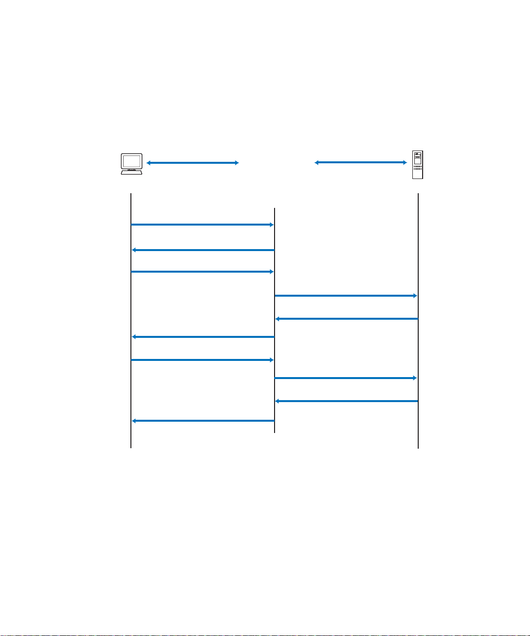
Figure 2-1 shows a typical message exchange initiated by the client.
802.1X Client
EAPOL
Ethernet
Port Unauthorized
EAPOL-Start
EAP-Request (Identity)
EAP-Response (Identity)
G8000
(Authenticator)
(RADIUS Client)
RADIUS-EAP
UDP/IP
Radius-Access-Request
RADIUS
Server
Radius-Access-Challenge
EAP-Request (Credentials)
EAP-Response (Credentials)
Radius-Access-Request
Radius-Access-Accept
EAP-Success
Port Authorized
Figure 2-1 Authenticating a Port Using EAPoL
Chapter 2: Port-based Network Access Control
41BMD00041, November 2008
Page 42

RackSwitch G8000 Application Guide
EAPoL message exchange
During authentication, EAPOL messages are exchanged between the client and the G8000
authenticator, while RADIUS-EAP messages are exchanged between the G8000 authenticator
and the RADIUS server.
Authentication is initiated by one of the following methods:
The G8000 authenticator sends an EAP-Request/Identity packet to the client
Clie nt sends an EAPOL-Start frame to the G8000 authen ticator, which responds with an
EAP-Request/Identity frame.
The client confirms its identity by sending an EAP-Response/Identity frame to the G8000
authenticator, which forwards the frame encapsulated in a RADIUS packet to the server.
The RADIUS authentication server chooses an EAP-supported authentication algorithm to
verify the client’s identity, and sends an EAP-Request packet to the client via the G8000
authenticator. The client then replies to the RADIUS server with an EAP-Response containing
its credentials.
Upon a successful authentication of the client by the server, the 802.1X-controlled port transitions from unauthorized to authorized state, and the client is allowed full access to services
through the controlled port. When the client later sends an EAPOL-Logoff message to the
G8000 authenticator, the port transitions from authorized to unauthorized state.
If a client that does not support 802.1X connects to an 802.1X-controlled port, the G8000
authenticator requests the client's identity when it detects a change in the operational state of
the port. The client does not respond to the request, and the port remains in the unauthorized
state.
NOTE – When an 802.1X-enabled client connects to a port that is not 802.1X-controlled, the client initiates the authentication process by sending an EAPOL-Start frame. When no response is
received, the client retransmits the request for a fixed number of times. If no response is
received, the client assumes the port is in authorized state, and begins sending frames, even if
the port is unauthorized.
Chapter 2: Port-based Network Access Control BMD00041, November 2008
42
Page 43

RackSwitch G8000 Application Guide
802.1X port states
The state of the port determines whether the client is granted access to the network, as follows:
Unauthorized
While in this state the port discards all ingress and egress traffic except EAP packets.
Authorized
When the client is successfully authenticated, the port transitions to the authorized state
allowing all traffic to and from the client to flow normally.
Force Unauthorized
You can configure this state that denies all access to the port.
Force Authorized
You can configure this state that allows full access to the port.
Use the 802.1X global configuration commands (dot1x) to configure 802.1X authentication
for all ports in the switch. Use the 802.1X port commands to configure a single port.
Chapter 2: Port-based Network Access Control
43BMD00041, November 2008
Page 44

RackSwitch G8000 Application Guide
Supported RADIUS attributes
The G8000 802.1X Authenticator relies on external RADIUS servers for authentication
with EAP. Table 2 lists the RADIUS attributes that are supported as part of
RADIUS-EAP authentication based on the guidelines specified in Annex D of the 802.1X
standard and RFC 3580.
Table 2 Support for RADIUS Attributes
# Attribute Attribute Value A-R A-A A-C A-R
1 User-Name The value of the Type-Data field from the supplicant’s
EAP-Response/Identity message. If the Identity is
unknown (i.e. Type-Data field is zero bytes in length), this
attribute will have the same value as the Calling-StationId.
4 NAS-IP-Address IP address of the authenticator used for Radius commu-
nication.
5 NAS-Port Port number of the authenticator port to which the suppli-
cant is attached.
24 St ate Server-specific value. This is sent unmodified back to the
server in an Access-Request that is in response to an
Access-Challenge.
30 Called-Station-ID The MAC address of the authenticator encoded as an
ASCII string in canonical format, e.g. 000D5622E3 9F.
31 Calling-Station-ID The MAC address of the supplicant encoded as an ASCII
string in canonical format, e.g. 00034B436206.
79 EAP-Message Encapsulated EAP packets from the supplicant to the
authentication server (Radius) and vice-versa. The
authenticator relays the decoded packet to both devices.
80 Message-Authentica-
tor
Always present whenever an EAP-Message attribute is
also included. Used to integrity-protect a packet.
10-10 0
1000
1000
0-1 0-1 0-1 0
1000
1000
1+ 1+ 1+ 1+
1111
87 NAS-Port-ID Name assigned to the authenticator port, e.g.
Server1_Port3
Legend:
RADIUS Packet Types: A-R (Access-Request), A-A (Access-Accept), A-C (Access-Challenge), A-R (Access-Reject)
RADIUS Attribute Support:
0 This attribute MUST NOT be present in a packet.
0+ Zero or more instances of this attribute MAY be present in a packet.
0-1 Zero or one instance of this attribute MAY be present in a packet.
1 Exactly one instance of this attribute MUST be present in a packet.
1+ One or more of these attributes MUST be present.
Chapter 2: Port-based Network Access Control BMD00041, November 2008
44
1000
Page 45

RackSwitch G8000 Application Guide
Configuration guidelines
When configuring EAPoL, consider the following guidelines:
The 802.1X port-based authentication is currently supported only in point-to-point config-
urations, that is, with a single supplicant connected to an 802.1X-enabled switch port.
When 802.1X is enabl e d, a port has to be in the authorized state before any ot her Layer 2
feature can be operationally enabled. For example, the STG state of a port is operationally
disabled while the port is in the unauthorized state.
The 802.1X suppli cant capability is not supported. Therefore, none of its ports can suc-
cessfully connect to an 802.1X-enabled port of another device, such as another switch,
that acts as an authenticator, unless access control on the remote port is disabled or is configured in forced-authorized mode. For example, if a G8000 is connected to another
G8000, and if 802.1X is enabled on both switches, the two connected ports must be configured in force-authorized mode.
The 802.1X standard has optional provisions for supporting dynamic virtual LAN
assignment via RADIUS tunnelling attributes, for example, Tunnel-Type (=VLAN),
Tunnel-Medium-Type (=802), and Tunnel-Private-Group-ID (=VLAN id).
These attributes are not supported and might affect 802.1X operations. Other unsupported
attributes include Service-Type, Session-Timeout, and Termination-Action.
RADIUS accounting service for 802.1X-authenticated devices or users is not supported.
Configuration changes performed using SNMP and the standard 802.1X MIB will take
effect immediately.
Chapter 2: Port-based Network Access Control
45BMD00041, November 2008
Page 46

RackSwitch G8000 Application Guide
Chapter 2: Port-based Network Access Control BMD00041, November 2008
46
Page 47

CHAPTER 3
VLANs
This chapter describes network design and topology considerations for using V irtual Local Area
Networks (VLANs). VLANs commonly are used to split up groups of network users into manageable broadcast domains, to create logical segmentation of workgroups, and to enforce security
policies among logical segments. The following topics are discussed in this chapter:
“VLANs and Port VLA N ID Nu mbers” on page 49
“VLAN Tagging” on page 51
“VLAN Topologies and Design Considerations” on page 55
This section discusses how you can connect users and segments to a host that supports
many logical segments or subnets by using the flexibility of the multiple VLAN system.
“Private VLANs” on page 59
NOTE – VLANs can be configured from the Command Line Interface (see “VLAN Configuration” as well as “Port Configuration” in the Command Reference).
BMD00041, November 2008 47
Page 48

RackSwitch G8000 Application Guide
Overview
Setting up virtual LANs (VLANs) is a way to segment networks to increase network flexibility
without changing the physical network topology. W ith network segmentation, each switch port
connects to a segment that is a single broadcast domain. When a switch port is configured to be
a member of a VLAN, it is added to a group of ports (workgroup) that belong to one broadcast
domain.
Ports are grouped into broadcast domains by assigning them to the same VLAN. Frames
received in one VLAN can only be forwarded within that VLAN, and multicast, broadcast, and
unknown unicast frames are flooded only to ports in the same VLAN. The G8000 supports
jumbo frames up to 9,216 bytes.
Chapter 3: VLANs BMD00041, November 2008
48
Page 49

RackSwitch G8000 Application Guide
VLANs and Port VLAN ID Numbers
VLAN numbers
The G8000 supports up to 1024 VLANs per switch. Even though the maximum number of
VLANs supported at any given time is 1024, each can be identified with any number between
1 and 4094. VLAN 1 is the default VLAN for all ports.
Viewing VLANs
VLAN information:
RS G8000 (config)# show vlan
VLAN Name Status Ports
---- ------------------------ ------ ------------------------1 VLAN 1 ena 1-48, XGE2-XGE4
po1-po104
2 VLAN 2 dis empty
Chapter 3: VLANs
49BMD00041, November 2008
Page 50

RackSwitch G8000 Application Guide
PVID numbers
Each port in the switch has a configurable default VLAN number, known as its PVID.
By default, the PVID for all ports is set to 1, which correlates to the default VLAN ID.
The PVID for each port can be configured to any VLAN number between 1 and 4094.
Viewing and Configuring PVIDs
Use the following CLI commands to view PVIDs:
Port information:
RS G8000# show interface information
Alias Port Tag Edge Lrn Fld PVID NAME VLAN(s)
----- ---- --- ---- --- --- ---- -------------- ------------------- 1 1 y n e e 1 1 1
2 2 y n e e 1 2 1
3 3 y n e e 1 3 1
4 4 y n e e 1 4 1
5 5 y n e e 1 5 1
6 6 y n e e 1 6 1
... ... ... ...
44 44 n n e e 1 44 1
45 45 n n e e 1 45 1
46 46 n n e e 1 46 1
47 47 n n e e 1 47 1
48 48 n n e e 1 48 1
XGE1 49 n n e e 1 49 1
XGE2 50 n n e e 1 50 1
XGE3 51 n n e e 1 51 1
XGE4 52 n n e e 1 52 1
* = PVID is tagged.
Port Configuration:
RS G8000 (config)# interface port 7
RS G8000 (config-if)# pvid 7
Each port on the switch can belong to one or more VLANs, and each VLAN can have any
number of switch ports in its membership. Any port that belongs to multiple VLANs, however,
must have VLAN tagging enabled (see “VLAN Tagging” on page 51).
Chapter 3: VLANs BMD00041, November 2008
50
Page 51

RackSwitch G8000 Application Guide
VLAN Tagging
Blade OS software supports IEEE 802.1Q VLAN tagging, providing standards-based VLAN
support for Ethernet systems.
Tagging places the VLAN identifier in the frame header of a packet, allowing each port to
belong to multiple VLANs. When you add a port to multiple VLANs, you also must enable
tagging on that port.
Since tagging fundamentally changes the format of frames transmitted on a tagged port, you
must carefully plan network designs to prevent tagged frames from being transmitted to
devices that do not support 802.1Q VLAN tags, or devices where tagging is not enabled.
Important terms used with the 802.1Q tagging feature are:
VLAN identifier (VID)—the 12-bit portion of the VLAN tag in the frame header that
identifies an explicit VLAN.
Port VLAN identifier (PVID)—a classification mechanism that associates a port with a
specific VLAN. For example, a port with a PVID of 3 (PVID =3) assigns all untagged
frames received on this port to VLAN 3. Any untagged frames received by the switch are
classified with the PVID of the receiving port.
Tagged frame—a frame that carries VLAN tagging information in the header. This VLAN
tagging information is a 32-bit field (VLAN tag) in the frame header that identifies the
frame as belonging to a specific VLAN. Untagged frames are marked (tagged) with this
classification as they leave the switch through a port that is configured as a tagged port.
Untagged frame— a frame that does not carry any VLAN tagging information in the
frame header.
Untagged member—a port that has been configured as an untagged member of a specific
VLAN. When an untagged frame exits the switch through an untagged member port, the
frame header remains unchanged. When a tagged frame exits the switch through an
untagged member port, the tag is stripped and the tagged frame is changed to an untagged
frame.
Tagged member—a port that has been configured as a tagged member of a specific
VLAN. When an untagged frame exits the switch through a tagged member port, the
frame header is modified to include the 32-bit tag associated with the PVID. When a
tagged frame exits the switch through a tagged member port, the frame header remains
unchanged (original VID remains).
Chapter 3: VLANs
51BMD00041, November 2008
Page 52
RackSwitch G8000 Application Guide
NOTE – If a 802.1Q tagged frame is received by a port that has VLAN-tagging disabled and the
port VLAN ID (PVID) is different than the VLAN ID of the packet, then the frame is dropped
at the ingress port.
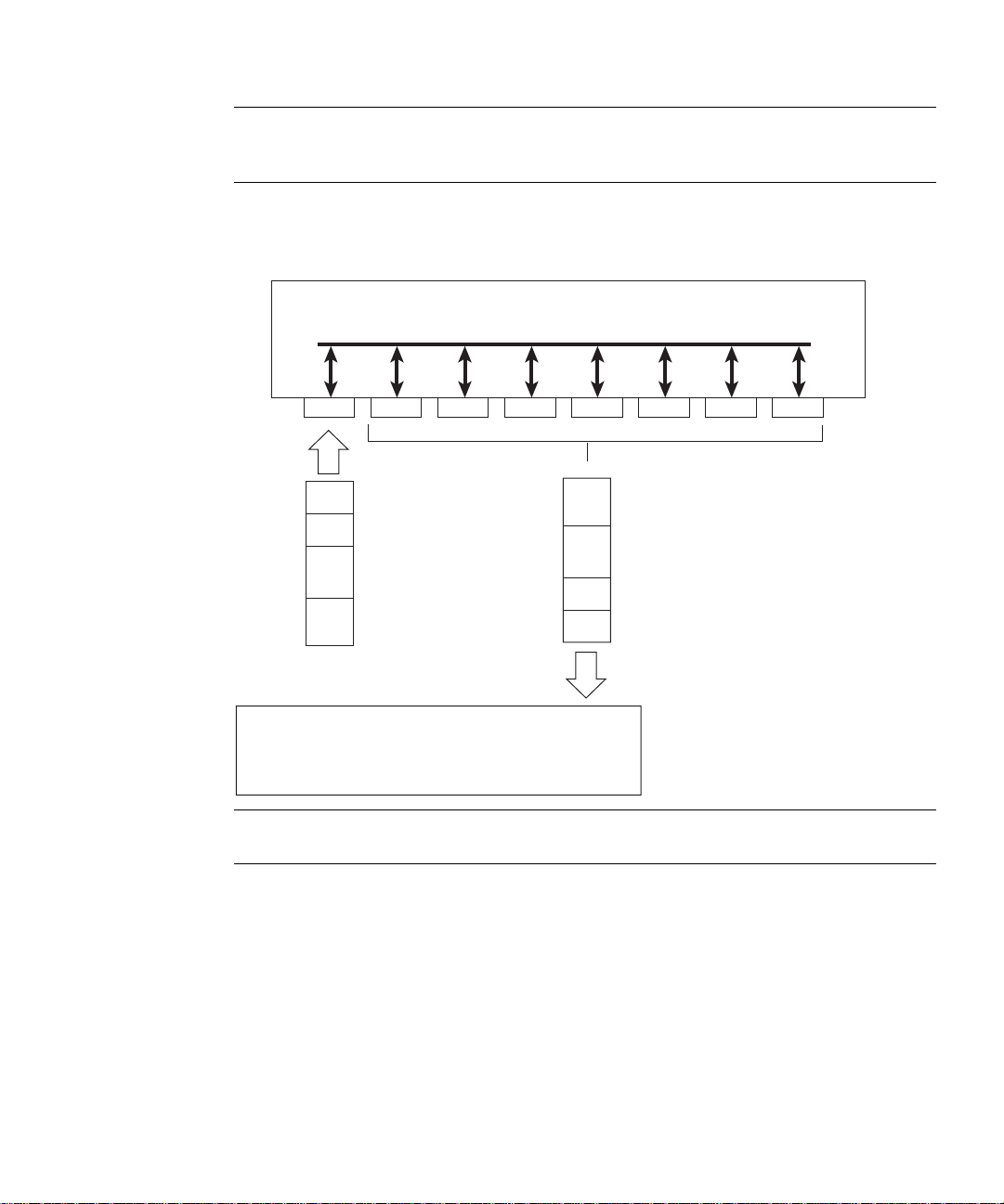
Figure 3-1 Default VLAN settings
802.1Q Switch
VLAN 1
Port 1
PVID = 1
DA
SA
Incoming
untagged
packet
Key
By default:
Data
CRC
All ports are assigned PVID = 1
All ports are untagged members of VLAN 1
Port 2 Port 3 Port 4 Por t 5
CRC
Outgoing
untagged packet
(unchanged)
Data
SA
DA
Port 6 ...
Port 7
BS45010A
NOTE – The port numbers specified in these illustrations may not directly correspond to the
physical port configuration of your switch model.
When a VLAN is configured, ports are added as members of the VLAN, and the ports are
defined as either tagged or untagged (see Figure 3-2 through Figure 3-5).
The default configuration settings for the G8000 has all ports set as untagged members of
VLAN 1 with all ports configured as PVID = 1. In the default configuration example shown in
Figure 3-1, all incoming packets are assigned to VLAN 1 by the default port VLAN identifier
(PVID =1).
Chapter 3: VLANs BMD00041, November 2008
52
Page 53
RackSwitch G8000 Application Guide
A
P
Tagged member
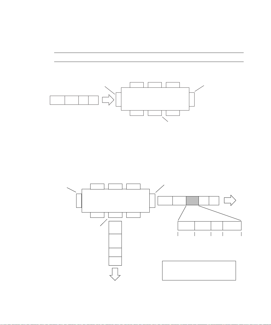
Figure 3-2 through Figure 3-5 illustrate generic examples of VLAN tagging. In Figure 3-2,
untagged incoming packets are assigned directly to VLAN 2 (PVID = 2). Port 5 is configured
as a tagged member of VLAN 2, and port 7 is configured as an untagged member of VLAN 2.
NOTE – The port assignments in the following figures are not meant to match the G8000.
Figure 3-2 Port-based VLAN assignment
PVID = 2
Untagged packet
B
efore
Port 1
DASADataCRC
Port 4
Port 6
Port 2 Port 3
802.1Q Switch
Port 7 Port 8
Tagged member
of VLAN 2
Port 5
Untagged member
of VLAN 2
BS45011A
As shown in Figure 3-3, the untagged packet is marked (tagged) as it leaves the switch through
port 5, which is configured as a tagged member of VLAN 2. The untagged packet remains
unchanged as it leaves the switch through port 7, which is configured as an untagged member
of VLAN 2.
Figure 3-3 802.1Q tagging (after port-based VLAN assignment)
VID = 2
Untagged memeber
untagged packet
Port 1
Port 4
Port 6 Port 7 Port 8
of VLAN 2
Outgoing
(unchanged)
Port 2 Port 3
802.1Q Switch
CRC
Data
SA
DA
of VLAN 2
Port 5
(*Recalculated)
Key
Priority
CFI
VID
DASADataCRC* Tag
8100 CFI
16 bits 3 bits 1 bits 12 bits
After
- User_priority
- Canonical format indicator
- VLAN identifier
VID = 2Priority
BS45012
Chapter 3: VLANs
53BMD00041, November 2008
Page 54
RackSwitch G8000 Application Guide
A
PVID = 2
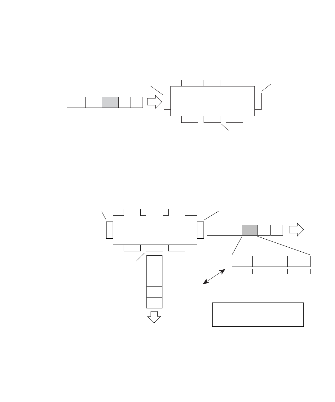
In Figure 3-4, tagged incoming packets are assigned directly to VLAN 2 because of the tag
assignment in the packet. Port 5 is configured as a tagged member of VLAN 2, and port 7 is
configured as an untagged member of VLAN 2.
Figure 3-4 802.1Q tag assignment
Tagged packet
B
efore
PVID = 2
DASATagDataCRC
Port 1
Port 4
Port 6
Port 2 Port 3
802.1Q Switch
Port 7 Port 8
Tagged member
of VLAN 2
Port 5
Untagged member
of VLAN 2
As shown in Figure 3-5, the tagged packet remains unchanged as it leaves the switch through
port 5, which is configured as a tagged member of VLAN 2. Howe ver, the tagged packet is
stripped (untagged) as it leaves the switch through port 7, which is configured as an untagged
member of VLAN 2.
Figure 3-5 802.1Q tagging (after 802.1Q tag assignment)
Port 5
Key
Tagged member
of VLAN 2
8100 CFI
16 bits 3 bits 1 bit 12 bits
After
Priority
CFI
VID
- User_priority
- Canonical format indicator
- VLAN identifier
DASADataCRC Tag
Port 1
Port 4
Port 6 Port 7 Port 8
Untagged member
of VLAN 2
Port 2 Port 3
802.1Q Switch
(*Recalculated)
CRC*
Data
Outgoing
SA
untagged packet
changed
DA
(tag removed)
BS45013A
VID = 2Priority
BS45014
Chapter 3: VLANs BMD00041, November 2008
54
Page 55

RackSwitch G8000 Application Guide
VLAN Topologies and Design Considerations
By default, the G8000 software is config ured so that tagging is disabled on all ports.
By default, the G8000 software is config ured so th at al l ports are members of VLAN 1.
If you configure Spanning Tree, note that Spanning Tree Groups 2-128 may contain only
one VLAN.
VLAN configuration rules
VLANs operate according to specific configuration rules. When creating VLANs, consider the
following rules that determine how the configured VLAN reacts in any network topology:
All ports involved in trunking and port mirroring must have the same VLAN configura-
tion. If a port is on a trunk with a mirroring port, the VLAN configuration cannot be
changed. For more information trunk groups, see “Port Trunking Example” on page 67.
All ports that are involved in port mirroring must have memberships in the same VLANs.
If a port is configured for port mirroring, the port’s VLAN membership cannot be
changed. For more information on configuring port mirroring, see “Monitoring Ports” on
page 140.
Chapter 3: VLANs
55BMD00041, November 2008
Page 56
RackSwitch G8000 Application Guide
Multiple VLANs with Tagging Adapters
Enterprise
Routing Switch
Enterprise
Routing Switch
Server 1
VLAN 1
Server 2
VLAN 1
Server 3
VLAN 2
Server 4
VLAN 3
Server 5
VLAN 1, 2
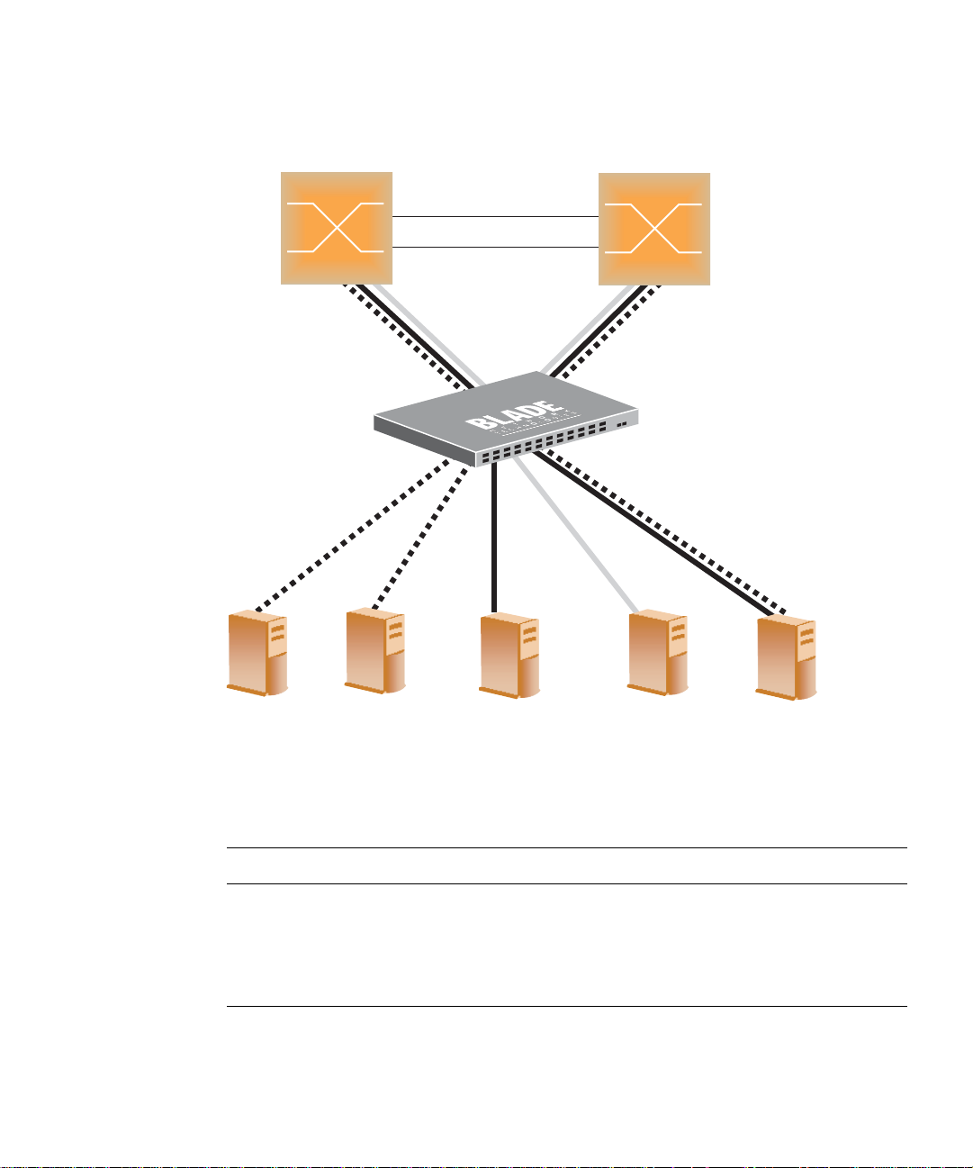
Figure 3-6 Example 1: Multiple VLANs with VLAN-Tagged Gigabit Adapters
The features of this VLAN are described below:
Component Description
G8000 switch This switch is configured with three VLANs that represent three differ-
ent IP subnets. Five ports are connected downstream to servers.
Two ports are connected upstream to routing switches.
Uplink ports are members of all three VLANs, with VLAN tagging
enabled.
Chapter 3: VLANs BMD00041, November 2008
56
Page 57

RackSwitch G8000 Application Guide
Component Description
Server 1 This server is a member of VLAN 1 and has presence in only one IP
subnet. The associated switch port is only a member of VLAN 1, so
tagging is disabled.
Server 2 This server is a member of VLAN 1 and has presence in only one IP
subnet. The associated switch port is only a member of VLAN 1, so
tagging is disabled.
Server 3 This server belongs to VLAN 2, and it is logically in the same IP sub-
net as Server 5.
The associated switch port has tagging disabled.
Server 4 A member of VLAN 3, this server can communicate only with other
servers via a router.
The associated switch port has tagging disabled.
Server 5 A member of VLAN 1 and VLAN 2, this server can communicate only
with Server 1, Server 2, and Server 3.
The associated switch port has tagging enabled.
Enterprise
Routing switches
These switches must have all three VLANs (VLAN 1, 2, 3) configured.
They can communicate with Server 1, Server 2, and Server 5 via
VLAN 1.
They can communicate with Server 3 and Server 5 via VLAN 2.
They can communicate with Server 4 via VLAN 3.
Tagging on switch ports is enabled.
NOTE – VLAN tagging is required only on ports that are connected to other switches or on ports
that connect to tag-capable end-stations, such as servers with VLAN-tagging adapters.
Chapter 3: VLANs
57BMD00041, November 2008
Page 58

RackSwitch G8000 Application Guide
VLAN configuration example
Use the following procedure to configure the example network shown in Figure 3-6.
1. Enable VLAN tagging on server ports that support multiple VLANs.
RS G8000 (config)# interface port 5
RS G8000 (config-if)# tagging
RS G8000 (config-if)# exit
2. Enable tagging on uplink ports that support multiple VLANs.
RS G8000 (config)# interface port 47
RS G8000 (config-if)# tagging
RS G8000 (config-if)# exit
RS G8000 (config)# interface port 48
RS G8000 (config-if)# tagging
RS G8000 (config-if)# exit
3. Configure the VLANs and their member ports.
RS G8000 (config)# vlan 2
RS G8000 (config-vlan)# enable
RS G8000 (config-vlan)# member 3
RS G8000 (config-vlan)# member 5
RS G8000 (config-vlan)# member 47
RS G8000 (config-vlan)# member 48
RS G8000 (config-vlan)# exit
RS G8000 (config)# vlan 3
RS G8000 (config-vlan)# enable
RS G8000 (config-vlan)# member 4,47,48
RS G8000 (config-vlan)# exit
By default, all ports are members of VLAN 1, so configure only those ports that belong to
other VLANs.
Chapter 3: VLANs BMD00041, November 2008
58
Page 59

RackSwitch G8000 Application Guide
Private VLANs
Private VLANs provide Layer 2 isolation between the ports within the same broadcast domain.
Private VLANs can control traffic within a VLAN domain, and provide port-based security for
host servers.
Use Private VLANs to partition a VLAN domain into sub-domains. Each sub-domain is comprised of one primary VLAN and one or more secondary VLANs, as follows:
Primary VLAN—carries unidirectional traffic downstream from promiscuous ports. Each
Private VLAN has only one primary VLAN. All ports in the Private VLAN are members
of the primary VLAN.
Secondary VLAN—Secondary VLANs are internal to a private VLAN domain, and are
defined as follows:
Isolated VLAN—carries unidirectional traffic upstream from the host servers toward
ports in the primary VLAN and the gateway. Each Private VLAN can contain only
one Isolated VLAN.
Community VLAN—carries upstream traffic from ports in the community VLAN to
other ports in the same community, and to ports in the primary VLAN and the gateway. Each Private VLAN can contain multiple community VLANs.
After you define the primary VLAN and one or more secondary VLANs, you map the secondary VLAN(s) to the primary VLAN.
Private VLAN ports
Private VLAN ports are defined as follows:
Promiscuous—A promiscuous port is a port that belongs to the primary VLAN. The pro-
miscuous port can communicate with all the interfaces, including ports in the secondary
VLANs (Isolated VLAN and Community VLANs). Each promiscuous port can belong to
only one Private VLAN.
Isolated—An isolated port is a host port that belongs to an isolated VLAN. Each isolated
port has complete layer 2 separation from other ports within the same private VLAN
(including other isolated ports), except for the promiscuous ports.
Traffic sent to an isolated port is blocked by the Private VLAN, except the traffic
from promiscuous ports.
Traffic received from an isolated port is forwarded only to promiscuous ports.
Chapter 3: VLANs
59BMD00041, November 2008
Page 60

RackSwitch G8000 Application Guide
Community—A community port is a host port that belongs to a community VLAN. Com-
munity ports can communicate with other ports in the same community VLAN, and with
promiscuous ports. These interfaces are isolated at layer 2 from all other interfaces in
other communities and from isolated ports within the Private VLAN.
Configuration guidelines
The following guidelines apply when configuring Private VLANs:
The default VLAN 1 cannot be a Private VLAN.
IG MP Snoop ing must be disabled on isolated VLANs.
Each secondary port’s (isolated port and community ports) PVID must match its corre-
sponding secondary VLAN ID.
Private VLA N ports cannot be members of a trunk group. Link Aggregation Control Pro-
tocol (LACP) must be turned off on ports within a Private VLAN.
Po rts within a secondary VLAN cannot be members of other VLANs.
All VLANs that comprise the Private VLAN must belong to the same Spanning Tree
Group.
Configuration example
Follow this procedure to configure a Private VLAN.
1. Select a VLAN and define the Private VLAN type as primary.
RS G8000 (config)# vlan 100
RS G8000 (config-vlan)# enable
RS G8000 (config-vlan)# member 2
RS G8000 (config-vlan)# private-vlan type primary
RS G8000 (config-vlan)# private-vlan enable
RS G8000 (config-vlan)# exit
Chapter 3: VLANs BMD00041, November 2008
60
Page 61
RackSwitch G8000 Application Guide
2. Configure a secondary VLAN and map it to the primary VLAN.
RS G8000 (config)# vlan 110
RS G8000 (config-vlan)# enable
RS G8000 (config-vlan)# member 3
RS G8000 (config-vlan)# member 4
RS G8000 (config-vlan)# private-vlan type isolated
RS G8000 (config-vlan)# private-vlan map 100
RS G8000 (config-vlan)# private-vlan enable
RS G8000 (config-vlan)# exit
3. Verify the configuration.
RS G8000 (config)# show private-vlan
Private-VLAN Type Mapped-To Status Ports
------------ --------- ---------- ---------- ----------------100 primary 110 ena 2
110 isolated 100 ena 3-4
Chapter 3: VLANs
61BMD00041, November 2008
Page 62

RackSwitch G8000 Application Guide
Chapter 3: VLANs BMD00041, November 2008
62
Page 63

CHAPTER 4
Ports and Trunking
Trunk groups can provide super-bandwidth, multi-link connections between switches or other
trunk-capable devices. A trunk group is a group of ports that act to gether, combining their
bandwidth to create a single, larger virtual link. This chapter provides configuration background and examples for trunking multiple ports together:
““Overview” on page 64”
“Port Trunking Example” on page 67
“Configurable Trunk Hash Algorithm” on page 69
“Link Aggregation Control Protocol” on page 70
BMD00041, November 2008 63
Page 64

RackSwitch G8000 Application Guide
Overview
When using port trunk groups between two switches, as shown in Figure 4-1, you can create
a virtual link between the switches, operating up to 40 Gb per second, depending on how
many physical ports are combined. Each G8000 supports up to 52 static trunk groups
(portchannels) and up to 52 LACP trunk groups, consisting of 1-8 ports in each group.
Trunk groups are also useful for connecting a G8000 to third-party devices that support link
aggregation, such as Cisco routers and switches with EtherChannel technology (not ISL trunking technology) and Sun's Quad Fast Ethernet Adapter. T r unk Group technology is compatible
with these devices when they are configured manually.
Statistical load distribution
Network traffic is distributed statistically between the ports in a trunk group. The switch can
use a combination of Layer 2 MAC and Layer 3 IP address information, present in each transmitted frame, to determine load distribution.
Each packet’s particular MAC or IP address information results in selecting one line in the
trunk group for data transmission. The more data streams feeding the trunk lines, the more
evenly traffic distribution becomes.
Built-In fault tolerance
Since each trunk group is comprised of multiple physical links, the trunk group is inherently
fault tolerant. As long as one connection between the switches is available, the trunk remains
active.
Statistical load balancing is maintained whenever a port in a trunk group is lost or returned to
service.
Chapter 4: Ports and Trunking BMD00041, November 2008
64
Page 65

RackSwitch G8000 Application Guide
Before you configure static trunks
When you create and enable a static trunk, the trunk members (switch ports) take on certain
settings necessary for correct operation of the trunking feature.
Before you configure your trunk, you must consider these settings, along with specific configuration rules, as follows:
1. Read the configuration rules provided in the section, “Static trunk group configuration
rules” on page 65.
2. Determine which switch ports (up to eight) are to become trunk members (the specific
ports making up the trunk).
Ensure that the chosen switch ports are set to enabled. Trunk member ports must have the
same VLAN and Spanning Tree configuration.
3. Consider how the existing Spanning Tree will react to the new trunk configuration. See
Chapter 4, “Spanning Tree Protocol” for Spanning Tree Group configuration guidelines.
4. Consider how existing VLANs will be affected by the addition of a trunk.
Static trunk group configuration rules
The trunking (portchannel) feature operates according to specific configuration rules. When
creating trunks, consider the following rules that determine how a trunk group reacts in any
network topology:
All trunks must originate from one device, and lead to one destination device.
Any physical switch port can belong to only one trunk group.
Trunking from third-party devices must comply with Cisco
When ports become members of a trunk, configuration parameters (except ACL and QoS)
are applied per trunk. When a trunk group is formed, these parameters are configured for
the trunk ID, which overrides the port-level parameters.
All trunk member ports must be assigned to the same VLAN configuration before the
trunk can be enabled.
You cannot change the VLAN membership for a trunk group’s member port. You can
change the VLAN membership of the trunk group.
When an active port is configured in a trunk, the port becomes a trunk member when you
enable the trunk. The Spanning Tree parameters for the port then change to reflect the new
trunk settings.
®
EtherChannel® technology.
Chapter 4: Ports and Trunking
65BMD00041, November 2008
Page 66

RackSwitch G8000 Application Guide
All trunk members must be in the same Spanning Tree Group (STG) and can belong to
only one Spanning Tree Group (STG). However if all ports are tagged, then all trunk ports
can belong to multiple STGs.
When a trunk is enabled, the trunk’s Spanning Tree participation setting takes precedence
over that of any trunk member.
You cannot configure a trunk member as a monitor port in a port-mirroring configuration.
Trunks cannot be monitored by a monitor port; however, trunk members can be moni-
tored.
All ports in static trunks must be have the same link configuration (speed, duplex, flow
control).
Chapter 4: Ports and Trunking BMD00041, November 2008
66
Page 67
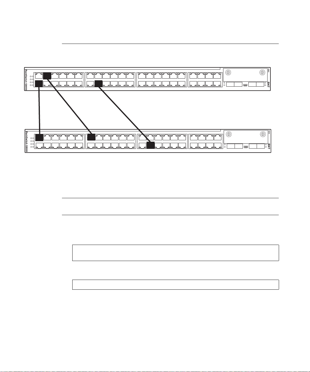
23
RackSwitch G8000 Application Guide
Port Trunking Example
In the example below, three ports are trunked between two switches.
Trunk 3: Ports 2, 23, and 30
2
30
Trunk 1: Ports 1, 7, and 32
1
Prior to configuring each switch in the above example, you must connect to the appropriate
switch’s Command Line Interface (CLI) as the administrator.
NOTE – For details about accessing and using any of the menu commands described in this
example, see the Command Reference.
1. Follow these steps on the G8000:
(a) Define a trunk group.
(b) Verify the configuration.
7
Figure 4-1 Port Trunk Group Configuration Example
RS G8000 (config)# portchannel 3 member 2,23,30
RS G8000 (config)# portchannel 3 enable
# show portchannel
Examine the resulting information. If any settings are incorrect, make appropriate changes.
32
Chapter 4: Ports and Trunking
67BMD00041, November 2008
Page 68
RackSwitch G8000 Application Guide
2. Repeat the process on the other switch.
RS G8000 (config)# portchannel 1 member 1,7,32
RS G8000 (config)# portchannel 1 enable
# show portchannel
3. Connect the switch ports that will be members in the trunk group.
Trunk group 3 (on the G8000) is now connected to trunk group 1 (on the other switch).
NOTE – In this example, two G8000 switches are used. If a third-party device supporting link
aggregation is used (such as Cisco routers and switches with EtherChannel technology or Sun's
Quad Fast Ethernet Adapter), trunk groups on the third-party device should be configured
manually. Connection problems could arise when using automatic trunk group negotiation on
the third-party device.
4. Examine the trunking information on each switch.
# show portchannel information
PortChannel 3: Enabled
port state:
2: STG 1 forwarding
23: STG 1 forwarding
30: STG 1 forwarding
Information about each port in each configured trunk group is displayed. Make sure that trunk
groups consist of the expected ports and that each port is in the expected state.
The following restrictions apply:
Any physical switch port can belong to only one trunk group.
Up to eight ports can belong to the same trunk group.
All ports in static trunks must be have the same link configuration (speed, duplex, flow
control).
Trunking from third-party devices must comply with Cisco
Chapter 4: Ports and Trunking BMD00041, November 2008
68
®
EtherChannel® technology.
Page 69

RackSwitch G8000 Application Guide
Configurable Trunk Hash Algorithm
This feature allows you to configure parameters for the trunk hash algorithm, instead of using
the default values.
Use the IP Trunk Hash commands to configure new default behavior for Layer 2 traffic and
Layer 3 traffic. The trunk hash settings affect both static trunks and LACP trunks.
You can select a minimum of one or a maximum of two parameters to create one of the
following configurations:
Source MAC (SMAC):
RS G8000 (config)# portchannel hash source-mac-address
Destination MAC (DMAC):
RS G8000 (config)# portchannel hash destination-mac-address
Source MAC (SMAC) + Destination MAC (DMAC):
RS G8000 (config)# portchannel hash source-destination-mac
So ur ce IP (SIP):
RS G8000 (config)# portchannel hash source-ip-address
Destination IP (DIP):
RS G8000 (config)# portchannel hash destination-ip-address
So ur ce IP (SIP) + Destination IP (DIP):
RS G8000 (config)# portchannel hash source-destination-ip
Chapter 4: Ports and Trunking
69BMD00041, November 2008
Page 70

RackSwitch G8000 Application Guide
Link Aggregation Control Protocol
Link Aggregation Control Protocol (LACP) is an IEEE 802.3 ad standard for grouping several
physical ports into one logical port (known as a dynamic trunk group or Link Aggregation
group) with any device that supports the standard. Please refer to IEEE 802.3ad-2002 for a full
description of the standard.
The 802.3ad standard allows standard Ethernet links to form a single Layer 2 link using the
Link Aggregation Control Protocol (LACP). Link aggregation is a method of grouping physical link segments of the same media type and speed in full duplex, and treating them as if they
were part of a single, logical link segment. If a link in a LACP trunk group fails, traffic is reassigned dynamically to the remaining link(s) of the dynamic trunk group.
NOTE – LACP implementation in the Blade OS does not support the Churn machine, an option
used to detect if the port is operable within a bounded time period between the actor
and the partner. Only the Marker Responder is implemented, and there is no marker protocol
generator.
A port’s Link Aggregation Identifier (LAG ID) determines how the port can be aggregated.
The Link Aggregation ID (LAG ID) is constructed mainly from the system ID and the port’s
admin key, as follows:
System ID is an integer value based on the switch’s MAC address and the system priority
assigned in the CLI.
Admin key
A port’s Admin key is an integer value (53-65535) that you can configure in the CLI. Each
switch port that participates in the same LACP trunk group must have the same admin key
value. The Admin key is local significant, which means the partner switch does not need to use
the same Admin key value.
For example, consider two switches, an Actor (the G8000) and a Partner (another switch), as
shown in Table 4-1.
Table 4-1 Actor vs. Partner LACP configuration
Actor Switch Partner Switch 1
Port 7 (admin key = 100) Port 1 (admin key = 50)
Port 8 (admin key = 100) Port 2 (admin key = 50)
In the configuration shown in Table 4-1, Actor switch port 7 and port 8 aggregate to form an
LACP trunk group with Partner switch port 1 and port 2.
Chapter 4: Ports and Trunking BMD00041, November 2008
70
Page 71

RackSwitch G8000 Application Guide
LACP automatically determines which member links can be aggregated and then aggregates
them. It provides for the controlled addition and removal of physical links for the link aggregation.
Each port on the switch can have one of the following LACP modes.
off (default)
The user can configure this port in to a regular static trunk group.
active
The port is capable of forming an LACP trunk. This port sends LACPDU packets to partner system ports.
passive
The port is capable of forming an LACP trunk. This port only responds to the LACPDU
packets sent from an LACP active port.
Each active LACP port transmits LACP data units (LACPDUs), while each passive LACP
port listens for LACPDUs. During LACP negotiation, the admin key is exchanged. The LACP
trunk group is enabled as long as the information matches at both ends of the link. If the admin
key value changes for a port at either end of the link, that port’s association with the LACP
trunk group is lost.
When the system is initialized, all ports by default are in LACP off mode and are assigned
unique admin keys. To make a group of ports aggregatable, you assign them all the same
admin key. You must set the port’s LACP mode to active to activate LACP negotiation. You
can set other port’s LACP mode to passive, to reduce the amount of LACPDU traffic at the initial trunk-forming stage.
Use the following command to check whether the ports are trunked:
RS G8000 # show lacp information
NOTE – If you configure LACP on ports with 802.1X network access control, make sure the
ports on both sides of the connection are properly configured for both LACP and 802.1X.
Chapter 4: Ports and Trunking
71BMD00041, November 2008
Page 72
RackSwitch G8000 Application Guide
LACP configuration guidelines
Consider the following guidelines when you configure LACP trunks:
When ports become members of a trunk, configuration parameters (except ACL and QoS)
are applied per trunk. When a trunk group is formed, these parameters are configured for
the trunk ID, which overrides the port-level parameters.
The range of potential LACP trunk IDs is 53-104.
When a LACP trunk forms, the trunk ID is determ ined by the lowest port number in the
trunk. For example, if the lowest port number is 1, then the LACP trunk ID is 53.
The LACP trunk ID can change if the link is lost on the lowest port in the group. When the
trunk ID changes, trunk-level parameters are cleared. To avoid losing configuration
parameters, configure LACP trunk-level parameters for all possible trunk IDs. Use the
port range configuration mode to set parameters for all of the ports that might participate
in LACP.
When a port becomes a member of a LACP trunk, LACP overrides the individual port
configuration.
If the port leaves the LACP trunk, you must reconfigure the port settings.
Each port that is configured to participate in LACP must be set to full duplex.
Configuring LACP
Use the following procedure to configure LACP on ports 2-6 to participate in link aggregation.
1. Configure port parameters. All ports that participate in the LACP trunk group must
have the same settings, including VLAN membership.
2. Select a range of ports and define the admin key. Only ports with the same admin key
can form a LACP trunk group.
RS G8000 (config)# interface port 2-6
RS G8000 (config-if)# lacp key 100
3. Set the LACP mode.
RS G8000 (config-if)# lacp mode active
RS G8000 (config-if)# exit
Chapter 4: Ports and Trunking BMD00041, November 2008
72
Page 73

CHAPTER 5
Spanning Tree
When multiple paths exist on a network, Spanning Tree Protocol configures the network so
that a switch uses only the most efficient path.
The following topics are discussed in this chapter:
“Overview” on page 74
“Rapid Spanning Tree Protocol” on page 80
“Per VLAN Rapid Spanning Tree” on page 83
“Multiple Spanning Tree Protocol” on page 86
“Fast Up link Convergence” on page 91
BMD00041, November 2008 73
Page 74

RackSwitch G8000 Application Guide
Overview
Spanning Tree Protocol detects and eliminates logical loops in a bridged or switched network.
When multiple paths exist, Spanning Tree configures the network so that a switch uses only the
most efficient path. If that path fails, Spanning Tree automatically sets up another active path
on the network to sustain network operations.
The G8000 supports the following Spanning Tree Protocols:
IEEE 802.1D (2004) Rapid Spanning Tree Protocol (RSTP). RSTP enhances the Spanning
Tree Protocol to provide rapid convergence on Spanning Tree Group 1.
IEEE 802.1Q (2003) Multiple Spanning Tree Protocol, which extends RSTP to multiple
Spanning Tree Groups. MSTP provides both rapid convergence and load balancing in a
VLAN environment, using multiple VLANs in each Spanning-Tree Group (STG).
Per VLAN Rapid Spanning Tree Plus Protocol (PVRST+), which enhances the RSTP
protocol by adding the ability to have multiple spanning tree groups. PVRST+ is based on
IEEE 802.1w Rapid Spanning Tree Protocol.
The relationship between port, trunk groups, VLANs, and Spanning Trees is shown in
Table 5-1.
Table 5-1 Ports, Trunk Groups, and VLANs
Switch Element Belongs to
Port Trunk group
or
One or more VLANs
Trunk group One or more VLANs
VLAN (non-default) RSTP: One VLAN per Spanning Tree group
PVRST+: One VLAN per Spanning Tree Group
MSTP: Multiple VLANs per Spanning Tree group
NOTE – Due to Spanning Tree’s sequence of discarding, learning, and forwarding, lengthy
delays may occur.
You can use a port’s spanning-tree edge command to permit a port that participates
in Spanning Tree to bypass the Discarding and Learning states, and enter directly into the
Forwarding state.
Chapter 5: Spanning Tree BMD00041, November 2008
74
Page 75

RackSwitch G8000 Application Guide
Bridge Protocol Data Units (BPDUs)
To create a Spanning Tree, the switch generates a configuration Bridge Protocol Data Unit
(BPDU), which it then forwards out of its ports. All switches in the Layer 2 network participating in the Spanning Tree gather information about other switches in the network through an
exchange of BPDUs.
A BPDU is a 64-byte packet that is sent out at a configurable interval, which is typically set for
two seconds. The BPDU is used to establish a path, much like a “hello” packet in IP routing.
BPDUs contain information about the transmitting bridge and its ports, including bridge MAC
address, bridge priority, port priority, and path cost.
The generic action of a switch upon receiving a BPDU is to compare the received BPDU to its
own BPDU that it will transmit. If the received BPDU is better than its own BPDU, it will
replace its BPDU with the received BPDU. Then, the switch uses this information to block any
necessary ports.
Determining the Path for Forwarding BPDUs
When determining which port to use for forwarding and which port to block, the G8000 uses
information in the BPDU, including each bridge ID. A technique based on the “lowest root
cost” is then computed to determine the most efficient path for forwarding.
Bridge Priority
The bridge priority parameter controls which bridge on the network is the STG root bridge.
To make one switch become the root bridge, configure the bridge priority lower than all other
switches and bridges on your network. The lower the value, the higher the bridge priority.
Use the following command to configure the spanning-tree bridge priority:
RS G8000 (config)# spanning-tree stp 1 bridge
priority <0-61440, in steps of 4096>
Chapter 5: Spanning Tree
75BMD00041, November 2008
Page 76

RackSwitch G8000 Application Guide
Port Priority
The port priority helps determine which bridge port becomes the root/designated port.
The case for the root port is when 2 switches are connected using a minimum of two links with
the same path-cost. The case for the designated port is in a network topology that has multiple
bridge ports with the same path-cost connected to a single segment—the port with the lowest
port priority becomes the designated port for the segment. Use the following command to
configure the spanning-tree port priority (Interface Port mode):
RS G8000 (config-if)# spanning-tree stp 1
priority <0-240, in steps of 16>
Port Path Cost
The port path cost assigns lower values to high-bandwidth ports, such as 10 Gigabit Ethernet,
to encourage their use. The objective is to use the fastest links so that the route with the lowest
cost is chosen. A value of 0 indicates that the default cost will be computed for an auto-negotiated link speed.
Use the following command to modify the port path cost:
RS G8000 (config-if)# spanning-tree stp 1 path-cost <0-200000000>
Spanning Tree Group configuration guidelines
This section provides important information on configuring Spanning Tree Groups (STGs):
Changing the Spanning Tree mode
When the spanning-tree mode is changed (for example, RSTP to MSTP),
You must reconfigure spanning-tree parameters for each STG, including VLAN assign-
ment.
If a STG in RSTP mode is disabled and then re-enabled, the STP topology does not
converge rapidly.
Chapter 5: Spanning Tree BMD00041, November 2008
76
Page 77

RackSwitch G8000 Application Guide
Assigning a VLAN to a Spanning Tree Group
If no VLANs exist beyond the default VLAN 1 see “Creating a VLAN” on page 78 for
information on adding ports to VLANs.
Assign the VLAN to the STG using the following command:
RS G8000 (config-if)# spanning-tree stp 1 vlan <1-4094>
If the association between the spanning-tree group and a VLAN is broken, the spanning-
tree parameters are cleared. Reconfigure all of the parameters for the STG.
Each STG must have a VLAN assigned to it before it becomes functional. You cannot
configure other STG settings until the VLAN is assigned. If the STG VLAN is unassigned, other configuration settings are cleared. Assign a VLAN and reconfigure the STG
settings.
NOTE – To ensure proper operation with switches that use Cisco Per VLAN Spanning
Tree (PVST+), you must either:
create a separate STG for each VLAN, or
manually add all associated VLANs into a single STG.
Chapter 5: Spanning Tree
77BMD00041, November 2008
Page 78

RackSwitch G8000 Application Guide
Creating a VLAN
When you create a VLAN, that VLAN automatically belongs to STG 1, the default STG.
You can assign the VLAN to another STG.
Move a newly created VLAN to an existing STG by following this order:
Create the VLAN.
Enable the VLAN.
Add the VLAN to an existing STG.
VLANs must be contai ned within a single STG; a VLAN cannot span multiple STGs. By
confining VLANs within a single STG, you avoid problems wit h spanning tree blocking
ports and causing a loss of connectivity within the VLAN. When a VLAN spans multiple
switches, it is recommended that the VLAN remain within the same Spanning Tree Group
(have the same STG ID) across all the switches.
If ports are tagged, all tagged ports can belong to multiple STGs.
A port cannot be added directly to an STG. First add the port to a VLAN, then add the
VLAN to the STG.
Rules for VLAN Tagged ports
Tagged ports can belong to more than one STG.
Unta gged ports can belong to only one STG.
Adding and removing ports from STGs
When you add a port to a V L AN that belongs to an STG, the VLAN’s member port is
added to the STG. However, if the port you are adding is an untagged port and is already a
member of an STG, that port will be removed from this STG and added to the new STG.
An untagged port cannot belong to more that one STG.
For example, assume that VLAN 2 belongs to STG 2. You add an untagged port (port 5)
that belongs to STG 2 to VLAN 2. The port becomes a member of STG 2, and the switch
displays a message to inform you that the PVID changed from 1 to 2:
"Port 5 is an UNTAGGED port and its PVID changed from 1 to 2.
When you remove a port from a VLAN that belongs to an STG, that port is removed from
the STG. However, if that port belongs to another VLAN in the same STG, the port
remains in the STG.
Chapter 5: Spanning Tree BMD00041, November 2008
78
Page 79

RackSwitch G8000 Application Guide
As an example, assume that port 1 belongs to VLAN 2, and VLAN 2 belongs to STG 2.
When you remove port 1 from VLAN 2, port 1 is also removed from STG 2. The port
moves to the default VLAN 1.
However, if port 1 belongs to both VLAN 1 and VLAN 2 and both VLANs belong to
STG 1, removing port 1 from VLAN 2 does not remove port 1 from STG 1 because
VLAN 1 is still a member of STG 1.
An STG cannot be del eted, only disabled. If you disable the STG while it still contains
VLAN members, Spanning Tree will be off on all ports belonging to that VLAN.
The relationship between port, trunk groups, VLANs, and Spanning Trees is shown in
Table 5-1.
Chapter 5: Spanning Tree
79BMD00041, November 2008
Page 80

RackSwitch G8000 Application Guide
Rapid Spanning Tree Protocol
Rapid Spanning Tree Protocol (RSTP) provides rapid convergence of the spanning tree and
provides for fast re-configuration critical for networks carrying delay-sensitive traffic such as
voice and video. RSTP significantly reduces the time to reconfigure the active topology of the
network when changes occur to the physical topology or its configuration parameters. RSTP
reduces the bridged-LAN topology to a single Spanning Tree.
RSTP parameters are configured in Spanning Tree Group 1. STP Groups 2-128 do not apply to
RSTP. There are new STP parameters to support RSTP, and some values to existing parameters
are different.
RSTP is compatible with devices that run 802.1D (1998) Spanning Tree Protocol. If the switch
detects 802.1D (1998) BPDUs, it responds with 802.1D (1998)-compatible data units. RSTP is
not compatible with Per VLAN Spanning Tree (PVST+) protocol.
Port state changes
The port state controls the forwarding and learning processes of Spanning Tree. In RSTP, the
port state has been consolidated to the following: discarding, learning, and forwarding. Table 3
compares the port states between 802.1D (1998) Spanning Tree and 802.1D (2004) Rapid
Spanning Tree.
Table 3 RSTP vs. STP Port states
Operational status STP Port State RSTP Port State
Enabled Blocking Discarding
Enabled Listening Discarding
Enabled Learning Learning
Enabled Forwarding Forwarding
Disabled Disabled Discarding
Chapter 5: Spanning Tree BMD00041, November 2008
80
Page 81

RackSwitch G8000 Application Guide
Port Type and Link Type
Spanning Tree configuration includes the following parameters to support
RSTP and MSTP: edge port and link type.
Edge Port
A port that does not connect to a bridge is called an edge port. Edge ports can start forwarding
as soon as the link is up.
Edge ports do not take part in Spanning Tree, and should not receive BPDUs. A port with Edge
enabled is intended to be connected directly to a host. If a port with edge enabled does receive
a BPDU, it immediately begins working as a normal port, and participates in Spanning Tree.
Link Type
The link type determines how the port behaves in regard to Rapid Spanning Tree. The link type
corresponds to the duplex mode of the port. A full-duplex link is point-to-point (p2p), while a
half-duplex link should be configured as shared. If you select auto as the link type, the port
dynamically configures the link type.
RSTP configuration guidelines
This section provides important information about configuring Rapid Spanning Tree Groups:
When RSTP is turned on, STP parameters app ly onl y to STP Group 1.
When RSTP is turned on, STG 2-128 are turned off.
When RSTP is turned on, all VLANs are moved to Spanning Tree Group 1.
Chapter 5: Spanning Tree
81BMD00041, November 2008
Page 82

RackSwitch G8000 Application Guide
RSTP configuration example
This section provides steps to configure Rapid Spanning Tree on the G8000, using the
Command-Line Interface (ISCLI).
Rapid Spanning Tree Protocol is the default setting on the G8000.
Configure Rapid Spanning Tree
Rapid Spanning Tree is the default Spanning Tree mode on the G8000.
1. Configure port and VLAN membership on the switch.
2. Set the Spanning Tree mode to Rapid Spanning Tree.
RS G8000 (config)# spanning-tree mode rstp
Chapter 5: Spanning Tree BMD00041, November 2008
82
Page 83

RackSwitch G8000 Application Guide
Per VLAN Rapid Spanning Tree
Per VLAN Rapid Spanning Tree Plus Protocol (PVRST+) enhances the RSTP
protocol by adding the ability to have multiple spanning tree groups. PVRST+ is based on
IEEE 802.1w Rapid Spanning Tree Protocol.
In PVRST mode, the G8000 supports a maximum of 128 Spanning Tree Groups (STGs).
Multiple STGs provide multiple data paths, which can be used for load-balancing and redundancy.
T o enable load balancing between two G8000s using multiple STGs, configure each path with
a different VLAN and then assign each VLAN to a separate STG. Each STG is independent.
Each STG sends its own Bridge Protocol Data Units (BPDUs), and each STG must be configured independently.
The STG, or bridge group, forms a loop-free topology that incl udes one or more virtual LANs
(VLANs). The switch supports 128 STGs running simultaneously. The default STG 1 may
contain multiple VLANs. STGs 2-128 each may contain only one VLAN.
Default Spanning Tree configuration
In the default configuration, a single STG (STG 1) includes all ports on the switch.
This is called the default STG. Although ports can be added to or deleted from the default STG,
the default STG cannot be deleted from the system.
All other STGs, except the default STG 1, are empty and you must assign a VLAN to the STG .
However, you cannot assign ports directly to an STG . Add ports to a VLAN and add the VLAN
to the STG. Each STG is enabled by default, and assigned an ID number from 2 to 128.
Chapter 5: Spanning Tree
83BMD00041, November 2008
Page 84
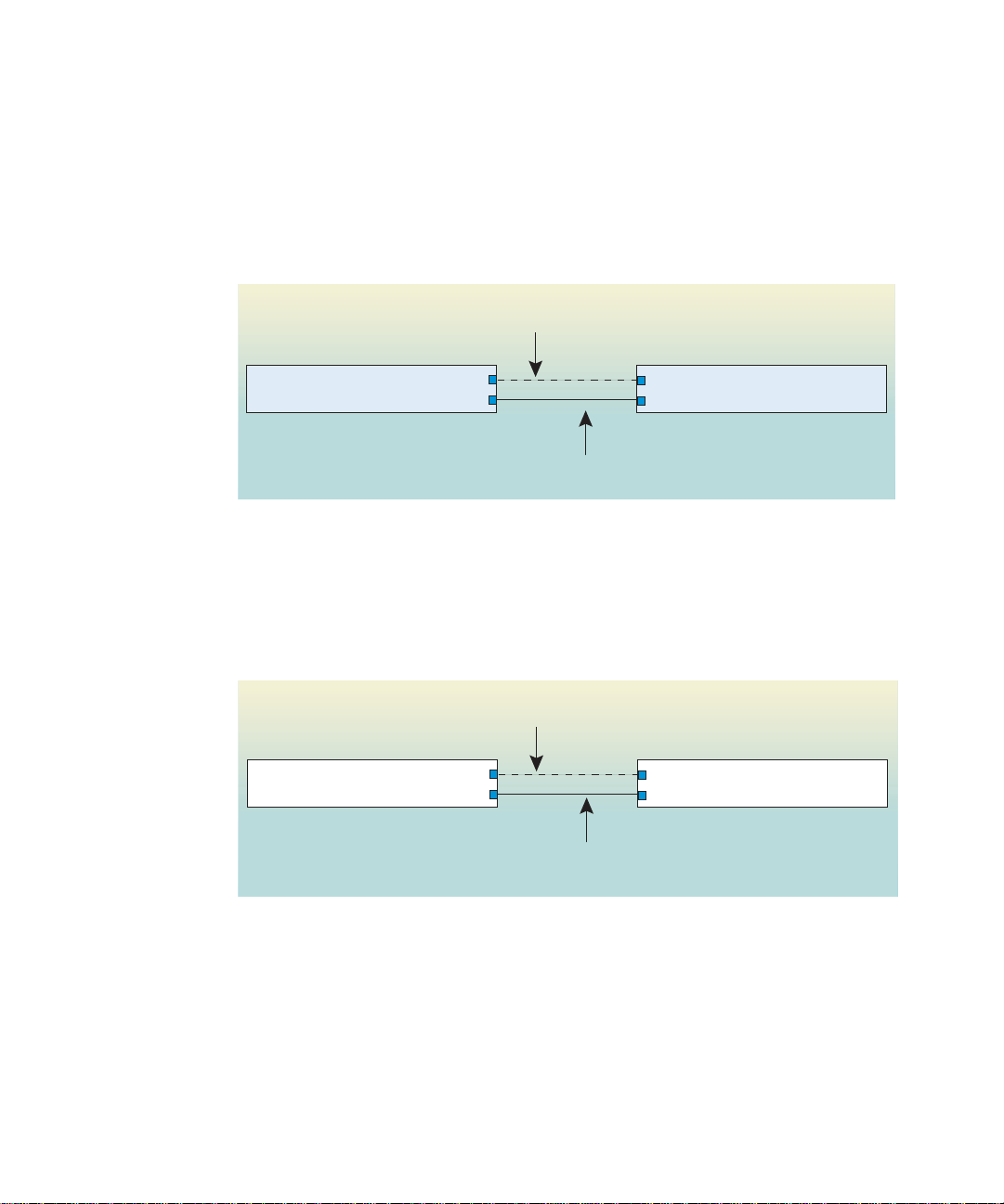
RackSwitch G8000 Application Guide
Why do we need multiple Spanning Trees?
The following examples describe why we need multiple spanning trees.
In Figure 5-1, VLAN 1 and VLAN 2 pass traffic between switch 1 and switch 2. If you have a
single Spanning Tree Group, the switches see an apparent physical loop, and one VLAN may
become blocked, affecting connectivity, even though no logical loop exists. VLAN 2 traffic is
blocked unnecessarily.
VLAN 1, STG 1
Switch 1
VLAN 2 traffic blocked by STG 1
X
VLAN 2, STG 1
Switch 2
Figure 5-1 Two VLANs on one Spanning Tree Group
In Figure 5-2, VLAN 1 and VLAN 2 belong to different Spanning Tree Groups. The two
instances of Spanning Tree separate the topology without forming a loop. Both VLANs can
forward packets between the switches without losing connectivity.
VLAN 1, STG 1
Switch 1
VLAN 2, STG 2
VLAN 1 passes traffic on STG 1
VLAN 2 passes traffic on STG 2
Switch 2
Figure 5-2 Two VLANs, each on a different Spanning Tree Group
Chapter 5: Spanning Tree BMD00041, November 2008
84
Page 85

RackSwitch G8000 Application Guide
PVRST configuration guidelines
This section provides important information about configuring Per VLAN Rapid Spanning
Tree Groups:
By default, STGs 2-128 are empty, and STG 1 contains all configured VLANs until indi-
vidual VLANs are assigned to other STGs. The G8000 allows only one VLAN per STG,
except for STG 1.
If the ports are tagged, each port sends out a special BPDU containing the tagged informa-
tion.
When a tagged port belongs to more than one STG, the egress BPDUs are tagged to distin-
guish the BPDUs of one STG from those of another STG.
Configuring PVRST
This configuration shows how to configure PVRST+ on the switch.
1. Set the Spanning-tree mode to PVRST+.
RS G8000 (config)# spanning-tree mode pvrst
2. Configure port membership for VLAN 1 and VLAN 2. Define the STGs for each VLAN.
By default, port 1 is a member of VLAN 1, and VLAN 1 is assigned to STG 1.
Add port 2 to VLAN 2, and assign VLAN 2 to STG 2.
RS G8000 (config)# vlan 2
RS G8000 (config-vlan)# enable
RS G8000 (config-vlan)# member 2
RS G8000 (config-vlan)# stg 2
RS G8000 (config-vlan)# exit
Chapter 5: Spanning Tree
85BMD00041, November 2008
Page 86

RackSwitch G8000 Application Guide
Multiple Spanning Tree Protocol
Multiple Spanning Tree extends Rapid Spanning Tree Protocol through multiple Spanning
Tree Groups, using multiple VLANs in each STG. MSTP supports up to 32 Spanning-Tree
instances, that correspond to STP Groups 1-32.
For more information about Spanning Tree Protocol, see Chapter 5, “Spanning Tree.”
In Multiple Spanning Tree Protocol (MSTP), several VLANs can be mapped to each Span-
ning-Tree instance. Each Spanning-Tree instance is independent of other instances. MSTP
allows frames assigned to different VLANs to follow separate paths, each path based on an
independent Spanning-Tree instance. This approach provides multiple forwarding paths for
data traffic, enabling load-balancing, and reducing the number of Spanning-Tree instances
required to support a large number of VLANs.
MSTP Region
A group of interconnected bridges that share the same attributes is called an MST region. Each
bridge within the region must share the following attributes:
Alphanumeric name
Revision number
VLAN-to STG mapping scheme
MSTP provides rapid re-configuration, scalability and control due to the support of regions,
and multiple Spanning-Tree instances support within each region.
Common Internal Spanning Tree
The Common Internal Spanning Tree (CIST) provides a common form of Spanning Tree Protocol, with one Spanning-Tree instance that can be used throughout the MSTP region.
CIST allows the switch to interoperate with legacy equipment, including devices that run
IEEE 802.1D (1998).
CIST allows the MSTP region to act as a virtual bridge to other bridges outside of the region,
and provides a single Spanning-Tree instance to interact with them.
CIST port configuration includes Hello time, path-cost, and interface priority. These parameters do not affect Spanning Tree Groups 1-32. They apply only when the CIST is used.
Chapter 5: Spanning Tree BMD00041, November 2008
86
Page 87

RackSwitch G8000 Application Guide
MSTP configuration guidelines
This section provides important information about configuring Multiple Spannin g Tree
Groups:
When MSTP is turned on, the switch automatically moves all VLANs to the CIST.
When MSTP is turned off, the switch moves all VLANs from the CIST to STG 1.
When enabling MSTP, Region Name must be configured, and a default version number of
0 (zero) is configured automatically. Each bridge in the region must have the same name,
version number, and VLAN mapping.
Figure 5-3 shows how multiple Spanning Trees can provide redundancy without wasting any
uplink ports. In this example, the server ports are split between two separate VLANs. Both
VLANs belong to two different Multiple Spanning Tree (MSTP) groups. The Spanning Tree
priority values are configured so that each routing switch is the root for a different MSTP
instance. All of the uplinks are active, with each uplink port backing up the other.
Chapter 5: Spanning Tree
87BMD00041, November 2008
Page 88
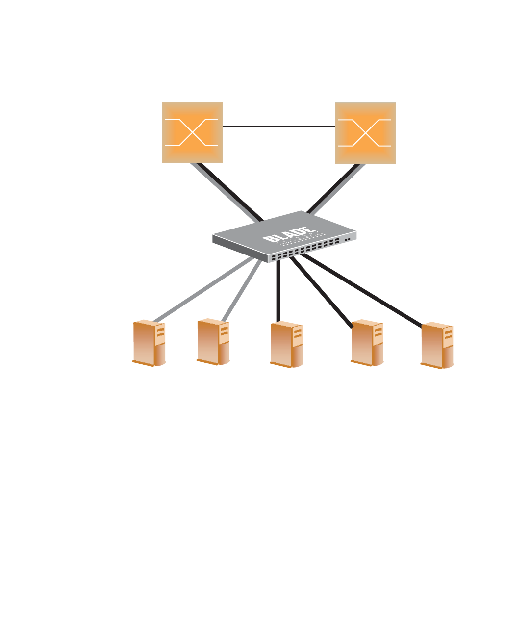
RackSwitch G8000 Application Guide
Enterprise
Routing Switch
(MSTP Group 1 root)
Passing VLAN 1
Blocking VLAN 2
Enterprise
Routing Switch
(MSTP Group 2 root)
Blocking VLAN 1
Passing VLAN 2
Server 1
VLAN 2
Server 2
VLAN 2
Server 3
VLAN 1
Server 4
VLAN 1
Server 5
VLAN 1
Figure 5-3 Implementing Multiple Spanning Tree Groups
Chapter 5: Spanning Tree BMD00041, November 2008
88
Page 89
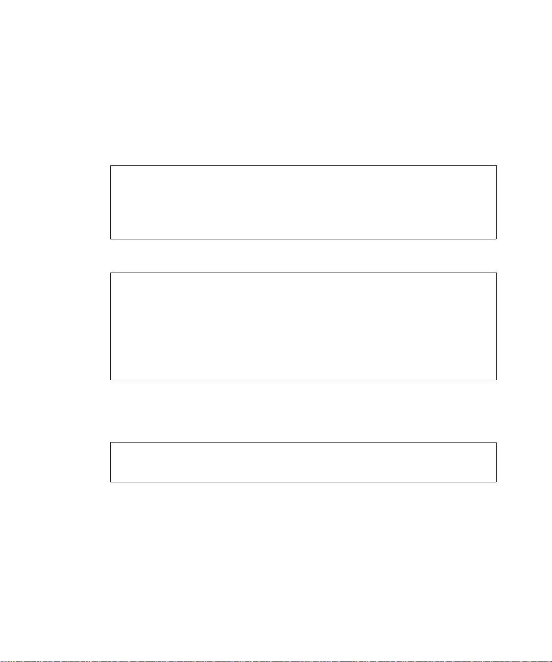
RackSwitch G8000 Application Guide
Configuring Multiple Spanning Tree Groups
This configuration shows how to configure MSTP Groups on the switch, as shown
in Figure 5-3.
1. Configure port membership and define the Spanning Tree groups for VLAN 1.
Enable tagging on uplink ports that share VLANs. Port 51 and port 52 connect to the Enterprise Routing switches.
RS G8000 (config)# interface port 51
RS G8000 (config-if)# tagging
RS G8000 (config-if)# exit
RS G8000 (config)# interface port 52
RS G8000 (config-if)# tagging
RS G8000 (config-if)# exit
Add server ports 1 and 2 to VLAN 1. Add uplink ports 51 and 52 to VLAN 1.
RS G8000 (config)# vlan 1
RS G8000 (config-vlan)# enable
RS G8000 (config-vlan)# member 3
RS G8000 (config-vlan)# member 4
RS G8000 (config-vlan)# member 5
RS G8000 (config-vlan)# member 51
RS G8000 (config-vlan)# member 52
RS G8000 (config-vlan)# stg 1
RS G8000 (config-vlan)# exit
2. Configure Multiple Spanning Tree Protocol.
Configure the MSTP region name, set the Spanning-tree mode to mst, and configure the
version.
RS G8000 (config)# spanning-tree mstp name MyRegion
RS G8000 (config)# spanning-tree mode mst
RS G8000 (config)# spanning-tree mstp version 100
Chapter 5: Spanning Tree
89BMD00041, November 2008
Page 90

RackSwitch G8000 Application Guide
3. Configure port membership and define the Spanning Tree groups for VLAN 2.
Add server ports 3, 4, and 5 to VLAN 2. Add uplink ports 51 and 52 to VLAN 2. Assign
VLAN 2 to Spanning Tree Group 2.
RS G8000 (config)# vlan 2
RS G8000 (config-vlan)# enable
RS G8000 (config-vlan)# member 1
RS G8000 (config-vlan)# member 2
RS G8000 (config-vlan)# member 51
RS G8000 (config-vlan)# member 52
RS G8000 (config-vlan)# stg 2
RS G8000 (config-vlan)# exit
NOTE – Each Spanning Tree Group (STG) is enabled by default.
Chapter 5: Spanning Tree BMD00041, November 2008
90
Page 91

RackSwitch G8000 Application Guide
Fast Uplink Convergence
Fast Uplink Convergence enables the G8000 to recover quickly from the failure of the primary
link or trunk group in a Layer 2 network using Spanning Tree Protocol. Normal recovery can
take as long as 50 seconds, while the backup link transitions from Blocking to Listening to
Learning and then Forwarding states. With Fast Uplink Convergence enabled, the G8000
immediately places the secondary path into Forwarding state, and sends multicasts of
addresses in the forwarding database (FDB) and ARP table over the secondary link so that
upstream switches can learn the new path.
NOTE – In order for Fast Uplink Convergence to be functional, the switch must be running in
PVRST+ mode and must be linked to switches running STP/PVST.
Configuration Guidelines
When you enable Fast Uplink Convergence, the G8000 automatically makes the following
configuration changes:
Sets the brid ge pri ority to 61440 so that it does not become the root switch.
Increases the cost of all ports by 30000, across all VLANs and Spanning Tree Groups.
This ensures that traffic never flows through the G8000 to get to another switch unless
there is no other path.
These changes are reversed if the feature is disabled.
Configuring Fast Uplink Convergence
Use the following CLI commands to enable Fast Uplink Convergence on all ports.
RS G8000 (config)# spanning-tree uplinkfast
Chapter 5: Spanning Tree
91BMD00041, November 2008
Page 92

RackSwitch G8000 Application Guide
Chapter 5: Spanning Tree BMD00041, November 2008
92
Page 93

CHAPTER 6
Quality of Service
Quality of Service features allow you to allocate network resources to mission-critical applications at the expense of applications that are less sensitive to such factors as time delays or network congestion. You can configure your network to prioritize specific types of traffic,
ensuring that each type receives the appropriate Quality of Service (QoS) level.
The following topics are discussed in this section:
“Overview” on page 94
“Using ACL Filters” on page 95
“Using Storm Control Filters” on page 105
“Using DSCP Values to Provide QoS” on page 106
“Using 802.1p Priority to Provide QoS” on page 111
“Queuing and Scheduling” on page 112
BMD00041, November 2008 93
Page 94
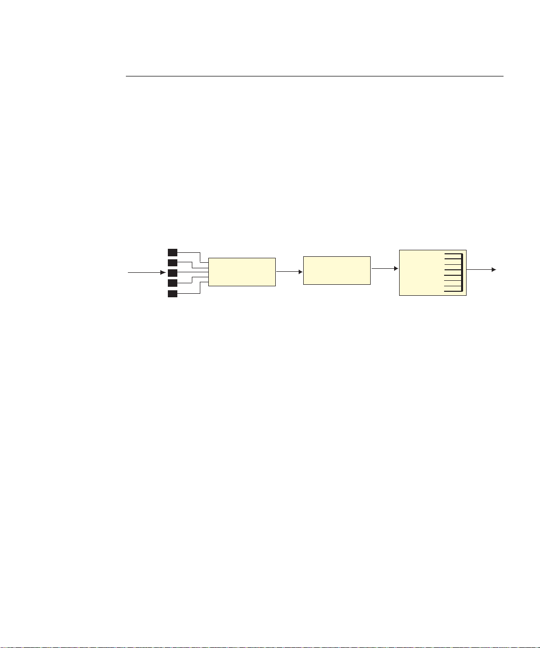
RackSwitch G8000 Application Guide
Overview
QoS helps you allocate guaranteed bandwidth to the critical applications, and limit bandwidth
for less critical applications. Applications such as video and voice must have a certain amount
of bandwidth to work correctly; using QoS, you can provide that bandwidth when necessary.
Also, you can put a high priority on applications that are sensitive to timing out or that cannot
tolerate delay, by assigning their traffic to a high-priority queue.
By assigning QoS levels to traffic flows on your network, you can ensure that network
resources are allocated where they are needed most. QoS features allow you to prioritize network traffic, thereby providing better service for selected applications.
Figure 6-1 shows the basic QoS model used by the switch.
Ingress
Ports
Classify
Packets
Perform
Actions
Queue and
Schedule
Egress
ACL
Filter
Figure 6-1 QoS Model
The basic QoS model works as follows:
Classify traffic:
Read DSCP value.
Read 802.1p priority value.
Match AC L fi lter parameters.
Perform actions:
Permit packets.
Deny packets.
Map 802.1p Priority to COS queue.
Map DSCP to COS queue.
Set the number of COS queues (1-8).
Queue and schedule traffic:
Permit/Deny
COS
Queue
Place packets in one of the COS queues.
Schedule transmission based on the COS queue.
Chapter 6: Quality of Service BMD00041, November 2008
94
Page 95

RackSwitch G8000 Application Guide
Using ACL Filters
Access Control Lists are filters that allow you to classify data packets according to a particular
content in the packet header, such as the source address, destination address, sou rce po rt number, destination port number, and others. Packet classifiers identify flows for more processing.
Each filter defines the conditions that must match for inclusion in the filter, and also the
actions that are performed when a match is made.
ACLs are used to control whether packets are forwarded or blocked at the switch ports. ACLs
can provide basic security for access to the network. For example, you can use an ACL to permit one host to access a part of the network, and deny another host access to the same area.
Each ACL contains rules that define the matching criteria for data packets. The ACL checks
each packet against its rules, to determine if there is a match. If the packet matches the ACL’s
rules, the ACL performs its configured action: either permit or deny the packet.
The G8000 supports the following ACL types:
MAC Extended ACLs
IP Standard A C Ls
IP Extended ACLs
MAC Extended ACLs
The switch supports up to 127 MAC extended ACLs, numbered from 1-65535. Use MAC
Extended ACLs to filter traffic using the following crit eria:
Source/destination MAC address
VLAN
Ethernet protocol
User priority criteria
To create a MAC Extended ACL:
RS G8000 (config)# access-list mac extended 1
RS G8000 (config-ext-macl)#
To delete a MAC Extended ACL:
RS G8000 (config)# no access-list mac extended 1
RS G8000 (config)#
Chapter 6: Quality of Service
95BMD00041, November 2008
Page 96
RackSwitch G8000 Application Guide
IP Standard ACLs
The switch supports up to 127 IP ACLs (standard and extended). IP Standard ACLs are numbered from 1-1000. Use IP Standard ACLs to filter traffic using source IP address/network
mask and destination IP address/network/mask.
To create an IP Standard ACL:
RS G8000 (config)# access-list ip standard 1
RS G8000 (config-std-nacl)#
To delete an IP Standard ACL:
RS G8000 (config)# no access-list ip standard 1
RS G8000 (config)#
IP Extended ACLs
The switch supports up to 127 IP ACLs (standard and extended). IP Extended ACLs are numbered from 1001-65535. Use IP Extended ACLs to filter traffic using the following criteria:
Source IP address/network mask
Destination IP address/network mask
IP protocol number or name as shown in Table 6-1
TCP/UDP application ports, as shown in Table 6-2 on page 97
TCP flags
ICM P message code and type
Type of Service (TOS) value
DSCP value
Chapter 6: Quality of Service BMD00041, November 2008
96
Page 97

Table 6-1 Well-known protocol types
Number Protocol Name
RackSwitch G8000 Application Guide
1
4
6
17
89
103
icmp
ip
tcp
udp
ospf
pim
Table 6-2 Well-known application ports
Number TCP/UDP
Application
20
21
22
23
25
37
42
43
53
69
70
ftp-data
ftp
ssh
telnet
smtp
time
name
whois
domain
tftp
gopher
Number TCP/UDP
79
80
109
110
111
119
123
143
144
161
162
To create an IP Extended ACL:
Application
finger
http
pop2
pop3
sunrpc
nntp
ntp
imap
news
snmp
snmptrap
Number TCP/UDP
Application
179
194
220
389
443
520
554
1645, 1812
1813
1985
bgp
irc
imap3
ldap
https
rip
rtsp
Radius
Radius Accounting
hsrp
RS G8000 (config)# access-list ip extended 1001
RS G8000 (config-ext-nacl)#
To delete an IP Extended ACL:
RS G8000 (config)# no access-list ip extended 1001
RS G8000 (config)#
Chapter 6: Quality of Service
97BMD00041, November 2008
Page 98

RackSwitch G8000 Application Guide
Understanding ACL priority
Each ACL has a unique priority, based on its number. The higher the ACL number, the higher
the priority, so ACL 1 has the lowest priority.
The priority is used to decide which ACL rule to apply when a packet matches one or more
ACLs. When an incoming packet matches the highest priority ACL, the ACL’s configured
action takes place. The other assigned ACLs are considered in numeric order, from highest to
lowest.
In the following example, the switch considers ACL 1003 before ACL 1001
because ACL 1003 has a higher priority. The order in which the ACLs are assigned to a port
does not affect their priority.
Port 1 access group
ACL IP Extended 1001:
TCP
Port number = 80
Action = permit
ACL IP Extended 1002:
TCP
Port number = 23
Action = deny
ACL IP Extended 1003:
TCP
Port number = less than 100
Action = permit
IP ACLs have precedence over MAC ACLs.
Assigning ACLs to a port
Once you configure an ACL, you must assign the ACL to a port. Each port can accept up to
127 ACLs. Note that higher priority ACLs are considered first, and their action takes precedence over lower-priority ACLs.
When you assign an ACL to a port, you must specify the filtering direction for traffic on the
port by including one of the following parameters:
in: ingress traffic
out: egress traffic
Chapter 6: Quality of Service BMD00041, November 2008
98
Page 99

RackSwitch G8000 Application Guide
NOTE – To ensure your ACLs function properly, do not assign the same ACL to different ports
using different filtering directions. It is recommended that you create two ACLs, one for
ingress traffic, and one for egress traffic.
To assign an ACL to a port:
RS G8000 (config)# interface port 1
RS G8000 (config-if)# ip access-group 1001 in
RS G8000 (config-if)# exit
To delete an ACL from a port:
RS G8000 (config)# interface port 1
RS G8000 (config-if)# no ip access-group 1001 in
RS G8000 (config-if)# exit
Each port retains its assigned ACLs, even if the port becomes a member of a trunk group
(portchannel).
Viewing ACL statistics
ACL statistics display how many packets hit (matched) each ACL. Use ACL statistics to check
filter performance, and debug the ACL filters. You must enable statistics for each ACL that
you want to monitor. Use the following command to enable statistics for the ACL:
RS G8000 (config)# access-list ip standard 1 statistics
Use the following command to view ACL statistics:
RS G8000 (config)# show access-list counters
Chapter 6: Quality of Service
99BMD00041, November 2008
Page 100
RackSwitch G8000 Application Guide
ACL configuration examples
Example 1
Use this configuration to block traffic to a specific host. All traffic that ingresses port 1 is
denied if it is destined for the host at IP address 100.10.1.1
1. Configure an Access Control List.
RS G8000 (config)# access-list ip standard 1
RS G8000 (config-std-nacl)# deny any host 100.10.1.1
RS G8000 (config-std-nacl)# exit
2. Assign the ACL to port 1.
RS G8000 (config)# interface port 1
RS G8000 (config-if)# ip access-group 1 in
RS G8000 (config-if)# exit
3. Verify the configuration.
RS G8000# show access-list 1
Standard IP Access List 1
--------------------------- Source IP address : 0.0.0.0
Source IP address mask : 0.0.0.0
Destination IP address : 100.10.1.1
Destination IP address mask : 255.255.255.255
In Port List : 1
Out Port List : NULL
Filter Action : Deny
User Priority : Nil
Statistics : Disabled
Status : Active
Chapter 6: Quality of Service BMD00041, November 2008
100
 Loading...