

Page 1

BLADEOS
™
Release Notes
1/10Gb Uplink Ethernet Switch Module for IBM BladeCenter
Version 6.3
Part Number: BMD 00178, Ap ril 2010
®
2350 Mission College B lv d.
Santa Clara, CA 9505 4
www.bladenetwork.net
Suite 600
Page 2

BLADEOS 6.3 Application Guide
Copyright © 2010 BLADE Network Technologies, Inc., 2350 Mission College Blvd. Suite 600, Santa
Clara, California, 95054, USA. All rights reserved. Reference number: BMD00178
This document is protected by copyright and distributed under licenses restricting its use, copying,
distribution, and decompilation. No part of this document may be reproduced in any form by any
means without prior written authoriz ation of BLADE Network T echnolo gies, Inc. Documentation is
provided “as is” without warranty of any kind, eithe r express or implied, includ ing any kind of
implied or express warranty of no n-infringement or the implied wa rranties of merchantability or
fitness for a particular purpose.
U.S. Government End Users: This document is provid ed with a “commercial item” as defined by F AR
2.101 (Oct. 1995) and contains “commercial technical data” and “commercial software
documentation” as those terms are used in FAR 12.211-12.212 (Oct. 1995). Government End Users
are authorized to use this d ocumentation only in ac cordance with thos e rights and restrictions set forth
herein, consistent with FAR 12.211- 12.212 (Oct. 1995), DFARS 227.7202 (JUN 1995) and DFARS
252.227-7015 (Nov. 1995).
BLADE Network Technologies, Inc. reserves the right to change any products described herein at any
time, and without notice. BL ADE Network T echnologies, Inc. assumes no responsibility or liability
arising from the use of produc ts described herein, except a s expressly agreed to in writing b y BLADE
Network Technologies, Inc. The use and purchase of this product does not convey a license under any
patent rights, trademark rig hts, or any other inte llectual property ri ghts of BLADE Network
T echnologies , Inc.
BLADE OS and BLADE are trademarks of BLADE Network Technologies, Inc. in the United States
and certain other countries. Any other trademarks appearing in this manual are owned by their
respective companies.
Originated in the USA.
2 BMD00178, April 2010
Page 3

Release Notes
The 1/10Gb Uplink Ethernet Switch Module (GbESM) is one of up to four switch modules that can
be installed in the IBM BladeCenter chassis.
These release notes provid e the late st information regarding BLADEOS 6.3 for th e 1/10G b Upl ink
Ethernet Switch Module. This supplement modifies information found in the complete
documentation:
BLADEOS 6.3 Application Guide for the 1/10Gb Uplink Ethernet Switch Module for IBM
BladeCenter
BLADEOS 6.3 Command Reference for the 1/10Gb Uplink Ethernet Switch Module for IBM
BladeCenter
BLADEOS 6.3 ISCLI Reference for the 1/10Gb Uplink Ethernet Switch Module for IBM
BladeCenter
BLADEOS 6.3 BBI Quick Guide for the 1/10Gb Uplink Ethernet Switch Module for IBM
BladeCenter
1/10Gb Uplink Ethernet Switch Module for IBM BladeCenter, Installation Guide
The publications listed above are available from the IBM support website:
http://www.ibm.com/systems/support
Please keep these release notes with your product manuals.
BMD00178, April 2010 3
Page 4
BLADEOS 6.3 Application Guide
Hardware Support
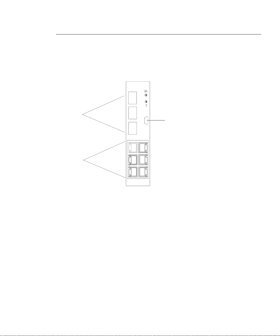
BLADEOS 6.3 software is supported only on the 1/10Gb Uplink Ethernet Switch Module for IBM
BladeCenter. The 1/10Gb Uplink ESM (GbESM) shown in Figure 1 is a high performance Layer
2-3 embedded network switch that features tight integration with IBM BladeCenter management
modules.
Figure 1 1/10Gb Uplink ESM Faceplate
1
SFP+ slots
10Gb Ethernet
RJ45 ports
1Gb Ethernet
2
3
4
7
9
6
The GbESM has the following port capacities:
Three external 10Gb SFP+ slots
Six external 1Gb Ethernet ports (RJ45)
One RS-232 serial console port
Two 100Mb internal management ports
Fourteen 1000Mb Ethernet internal ports
RS-232
console port
4 BMD00178, April 2010
Page 5

BLADEOS 6.3 Application Guide
The GbESM contains three 10 Gigabit Small Form-factor, Pluggable (SFP+) slots. The 10Gb SFP+
slots can accept 1Gb copper transceivers, 10Gb optical transceivers, or Direct Attach Cables
(DAC).
Note – If a DAC is not programmed to meet MSA specifications (including length identifier), the
switch disables the port and generates a syslog message indicating that the DAC is not approved.
The GbESM does not disable the SFP+ ports when using MSA-compliant DAC cables. For best
results, the following cables have been qualified to work with the switch:
Table 1 Recommended SFP+ transceiver
Part number Description
BN-SP-CBL-1M SFP+ Copper Direct Attach Cable - 1 meter
BN-SP-CBL-3M SFP+ Copper Direct Attach Cable - 3 meters
BN-SP-CBL-7M SFP+ Copper Direct Attach Cable - 7 meters
BN-SP-CBL-10M SFP+ Copper Direct Attach Cable - 10 meters
BMD00178, April 2010 5
Page 6

BLADEOS 6.3 Application Guide
Up dating the Swi tch Software Im age
The switch software image is the executable code running on the GbESM. A version of the image
ships with the switch, and comes pre-installed on the device. As new versions of the image are
released, you can upgrade the softwa re running on your switc h. To get the latest version of s oftware
available for your GbESM, go to:
http://www.ibm.com/systems/support
From the BLADEOS CLI, use the /boot/cur command to determine the current software version.
The typical upgrade process for the software image consists of the following steps:
Place the new image onto a FTP or TFTP server on your network, o r on a local com puter.
Transfer the new image to your switch.
Select the new software image to be loaded into switch memory the next time the switch is reset.
Loading New Software to Your Switch
The switch can store up to two different software images, called image1 and image2, as well as
boot software, called boot. When you load new software, you must specify where it should be
placed: either into image1, image2, or boot.
For example, if your active image is currently loaded into image1, you would probably load the
new image software into image2. This lets you test the new software and reload the origin al active
image (stored in image1), if needed.
Caution—When you upgrade the switch software image, always load the new boot image and the
!
new software image before you reset the switch. If you do not load a new boot image, your switch
might not boot properly (To recover, see “Recovering from a Failed Upgrade” on page 10).
To load a new software image to your switch, you will need the following:
The image and boot software loaded on a FTP or TFTP se rver on your network. For example:
Boot file: GbESM-1-10U-6.3.1.0_Boot.img
Image file: GbESM-1-10U-6.3.1.0_OS.img
Note – Be sure to download both the new boot file and the new image file.
The hostname or IP add ress of th e FTP or TFTP s erver
The name of the new soft ware image or boot file
Note – The DNS parameters must be configured if specifying hostnames.
6 BMD00178, April 2010
Page 7

BLADEOS 6.3 Application Guide
When the software requirements are met, use one of the following procedur es to download the new
software to your switch. You can use the BLADEOS CLI, the ISCLI, or the BBI to download and
activate new software.
Using the BLADEOS CLI
1. At the Boot Options# prompt, enter:
Boot Options# gtimg
2. Enter the name of the switch software to be replaced:
Enter name of switch software image to be replaced
["image1"/"image2"/"boot"]: <image>
3. Enter the hostname or IP address of the FTP or TFTP server.
Enter hostname or IP address of FTP/TFTP server: <hostname or IP address>
4. Enter the name of the new software file on the server.
Enter name of file on FTP/TFTP server: <filename>
The exact form of the name will vary by server. However , the file location is normally relative to the
FTP or TFTP directory (usually /tftpboot).
5. Enter your username for the server, if applicable.
Enter username for FTP server or hit return for
TFTP server: {<username>|<Enter>}
If entering an FTP server username, you will also be prompted for the password.
6. The system then prompts you to confirm your request.
Once confirmed, the software will load into the switch.
7. If software is loaded into a different image than the one most recently booted, the system will
prompt you whether you wish to run the new image at next boot. Otherwise, you can enter the
following command at the Boot Options# prompt:
Boot Options# image
The system informs you of which software image (image1 or image2) is currently set to be
loaded at the next reset, and prompts you to enter a new choice:
Currently set to use switch software "image1" on next reset.
Specify new image to use on next reset ["image1"/"image2"]:
Specify the image that contains the newly loaded software.
BMD00178, April 2010 7
Page 8

BLADEOS 6.3 Application Guide
Using the ISCLI
1. In Privileged EXEC mode, enter the following command:
Router# copy {tftp|ftp}{image1|image2|boot-image}
2. Enter the hostname or IP address of the FTP or TFTP server.
Address or name of remote host:
<name or IP address>
3. Enter the name of the new software file on the server.
Source file name: <filename>
The exact form of the name will vary by server. However , the file location is normally relative to the
FTP or TFTP directory (usually tftpboot).
4. Enter your username and password for the server, if applicable.
User name: {<username>|<Enter>}
5. The system prompts you to confirm your request.
Once confirmed, the software will load into the switch.
6. When loading is complete, use the following command in Global Config uration mode to select
which software image (image1 or image2) you want to run in switch memory for the next
reboot:
Router(config)# boot image {image1|image2}
The system will then verify which image is set to be loaded at the next reset:
Next boot will use switch software image1 instead of image2.
8 BMD00178, April 2010
Page 9

BLADEOS 6.3 Application Guide
Using the BBI
You can use the Browser-B ased Interface to load software onto the GbESM. Th e software image to
load can reside in one of the following locations:
FTP server
TFTP server
Local computer
After you log onto the BBI, perform the following steps to load a software image:
1. Click the Configure context tab in the toolbar.
2. In the Navigation Window, select System > Config/Image Control.
The Switch Image and Configuration Management page appears.
3. If you are loading software from your computer (HTTP client), skip this step and go to the next.
Otherwise, if you are loading software from a FTP/TFTP server, enter the server’s information in
the FTP/TFTP Settings section.
4. In the Image Settings section, select the image version you want to replace (Image for Transfer).
If you are loading software from a FTP/TFTP s erver, enter the file name and click G et Image.
If you are loading software from your computer, click Browse.
In the File Upload Dialog, select the file and click OK. Then click Download via Browser.
Once the image has loaded, the page refreshes to show the new software.
BMD00178, April 2010 9
Page 10

BLADEOS 6.3 Application Guide
Using the Boot Management Menu
The Boot Management menu allows you to switch the software image, reset the switch to factory
defaults, or to recover from a failed software download.
You can interrupt the boot process and enter the Boot Management menu from the serial console
port. When the system displays Memory Test, press <Shift B>. The Boot Management menu
appears.
Resetting the System ...
Memory Test ................................
Boot Management Menu
1 - Change booting image
2 - Change configuration block
3 - Xmodem download
4-Exit
Please choose your menu option: 1
Current boot image is 1. Enter image to boot: 1 or 2: 2
Booting from image 2
The Boot Management menu allows you to perform the following actions:
To change the booting image, press 1 and follow the screen prompts.
To change the configuration block, press 2, and follow the screen prompts.
To perform an Xmodem download, press 3 and follow the screen prompts.
To exit the Boot Management menu, press 4. The booting process continues.
Recovering from a Failed Upgrade
Use the following procedure to recover from a failed software upgrade.
1. Connect a PC to the serial port of the switch.
2. Open a terminal emulator program that supports XModem Download (for example, HyperT erminal,
CRT, PuTTY) and select the following serial port characteristics:
Speed: 9600 bps
Data Bits: 8
Stop Bits: 1
Parity: None
Flow Control: None
10 BMD00178, April 2010
Page 11

BLADEOS 6.3 Application Guide
3. Boot the switch and access the Boot Management menu by pressing <Shift B> while the Memory
Test is in progress and the dots are being displayed.
4. Select 3 for Xmodem downlo ad. When you see the following message, change the Serial Port
characteristics to 115200 bps:
## Switch baudrate to 115200 bps and press ENTER ...
5. Press <Enter> to set the system into download accept mode. When the readiness meter displays (a
series of “C” characters), start XModem on your terminal emulator.
6. Select the Boot Image to download. The XModem initiates the file transfer. When the download is
complete, a message similar to the following is displayed:
yzModem - CRC mode, 62494(SOH)/0(STX)/0(CAN) packets, 6 retries
Extracting images ... Do *NOT* power cycle the switch.
**** VMLINUX ****
Un-Protected 10 sectors
Erasing Flash............. done
Writing to Flash.............done
Protected 10 sectors
**** RAMDISK ****
Un-Protected 44 sectors
Erasing Flash............................................... done
Writing to Flash...............................................done
Protected 44 sectors
**** BOOT CODE ****
Un-Protected 8 sectors
Erasing Flash........... done
Writing to Flash...........done
Protected 8 sectors
BMD00178, April 2010 11
Page 12

BLADEOS 6.3 Application Guide
7. When you see the following message, change the Serial Port characteristics to 9600 bps:
## Switch baudrate to 9600 bps and press ESC ...
8. Press the Escape key (<Esc>) to re-display the Boot Management menu.
9. Select 3 to start a new XModem Download. When you see the following message, change the
Serial Port characteristics to 115200 bps:
## Switch baudrate to 115200 bps and press ENTER ...
10. Press <Enter> to continue the download.
11. Select the OS Image to download. The XModem initiates the file transfer. When the download is
complete, a message similar to the following is displayed:
yzModem - CRC mode, 27186(SOH)/0(STX)/0(CAN) packets, 6 retries
Extracting images ... Do *NOT* power cycle the switch.
**** Switch OS ****
Please choose the Switch OS Image to upgrade [1|2|n] :
12. Select the image number to load the new image (1 or 2). It is recommended that you select 1.
A message similar to the following is displayed:
Switch OS Image 1 ...
Un-Protected 27 sectors
Erasing Flash.............................. done
Writing to Flash..............................done
Protected 27 sectors
13. When you see the following message, change the Serial Port characteristics to 9600 bps:
## Switch baudrate to 9600 bps and press ESC ...
14. Press the Escape key (<Esc>) to re-display the Boot Management menu.
15. Select 4 to exit and boot the new image.
12 BMD00178, April 2010
Page 13

BLADEOS 6.3 Application Guide
New and Updated Features
BLADEOS 6.3 for 1/10Gb Uplink Ethernet Switch Module (GbESM) has been updated to include
new and enhanced features in support of Virtualization and Fibre Channel over Ethernet.
The list of features below summarizes the updated features. For more detailed information about
configuring GbESM features and capabilities, refer to the complete BLADEOS 6.3 documentation
as listed on page 3.
Stacking
A stack is a group of up to ei ght 1 / 10Gb Uplink ESM switches with BLAD EOS t hat work t oget h er
as a unified system. A stack has the following properties, regardless of the number of switches
included:
The network views the stack as a single entity.
The stack can be accessed and managed as a whole using standard switch IP interfaces.
Once the stacking links have been established (see below), the number of ports available in a
stack equals the total number of remaining ports of all the switches that are part of the stack.
The number of available IP interfaces, VLANs, Trunks, Trunk Links, and other switch
attributes are not aggregated among the switches in a stack. The totals for the stack as a whole
are the same as for any single switch configured in stand-alone mode.
Stacking Requirements
Before BLADEOS switches can form a stack, they must meet the following requirements:
All switches must be the same model (1/10Gb Uplink ESM).
Each switch must be installed with BLADEOS, version 6.3 or later. The same release version is
not required, as the Master switch will push a firmware image to each differing switch which is
part of the stack.
The recommended stacking topology is a bidirectional ring. T o achieve this, two external 10Gb
Ethernet ports on each switch must be reserved for stacking.By default, the first two 10Gb
Ethernet ports are used.
The cables used for connecting the switches in a stack carry low-level, inter-switch
communications as well as cross-stack data traffic critical to shared switching functions.
Always maintain the stability of stack links in order to avoid internal stack reconfiguration.
BMD00178, April 2010 13
Page 14

BLADEOS 6.3 Application Guide
Stacking Limitations
The GbESM with BLADEOS 6.3 can operate in one of two modes:
Default mode, which is the regular st and-alone (or non -stacked) mode.
Stacking mode, in which mu ltiple physical sw itches aggr egate functions as a single switchin g
device.
When in stacking mode, the following stand-alone features are not supported:
Active Multi-Path Protocol (AMP)
SFD
sFlow port monitoring
Uni-Directional Link Detection (UDLD)
Port flood blocking
BCM rate control
Link Layer Detection Pr otocol (LLDP )
Protocol-based VLANs
RIP
OSPF and OSPFv3
IPv6
Vi rtual Rout er Redun dancy P rotoco l (VRR P)
Loopback Interfaces
Router IDs
Route maps
Border Gateway Protocol (BGP )
MAC address notification
Static MAC address addi ng
Static multicast
MSTP
IGMP Relay and IGMPv3
Note – In stacking mode, switch menus and commands for unsupported features may be
unavailable, or may have no effect on switch operation.
14 BMD00178, April 2010
Page 15

BLADEOS 6.3 Application Guide
VMready
The switch’s VMready software m akes it virtualization aware. Servers that run hypervisor software
with multiple instances of one or more operating systems can present each as an independent virtual
machine (VM) with its own applications. With VMready, the GbESM automatically discovers
virtual machines (VMs), virtual switches, and VM NICs (collectively known as virtual entities or
VEs), and can distinguish between regular VMs, Service Console Interfaces, and Management
Interfaces. BLADEOS 6.3 supports up to 1024 VEs.
VEs may be placed into VM groups on the switch to define communication boundaries: VEs in a
given VM group are permitted to communicate with each other, while VEs in different groups are
not. VM groups also allow the configuration of group-level settings, such as virtualization policies
and ACLs.
The administrator can pre-provision VEs by adding the MAC addresses of potential VEs to a VM
group. When a VE with a pre-provisioned MAC address becomes connected to the switch, the
switch will automatically apply the appropriate group membership configuration.
The GbESM with VMready detects the migration of VEs across different hypervisors. As VEs
move, the GbESM NMotion
™
feature automatically moves the appropriate network configuration
as well. NMotion gives the switch the ability to maintain assigned group me m bership and
associated policies (such as VLAN Maps and VM policy bandwidth control) when a VE moves to a
different port on the switch.
VMready also works with VMware’s Virtual Center (vCenter) for advanced VE management. By
connecting with the vCenter, the switch can obtain information about distant VEs, push VM
configuration profiles to the VEs in distributed VM groups, and enhance VE migration.
VMready is configured from the Virtualization menu, available with the following CLI command:
# /cfg/virt
BMD00178, April 2010 15
Page 16

BLADEOS 6.3 Application Guide
VLAN Maps
A VLAN map (VMAP) is an Access Control List (ACL) that can be assigned to a VLAN rather
than to a switch port as with regular ACLs. In a virtualized environment, VMAPs allow you to
create traffic filtering and metering policies that are associated with a VM group VLAN, allowing
ACLs to follow VMs as they migrate between hypervisors.
VMAPs are configured from the ACL menu, available with the following CLI command:
# /cfg/acl/vmap <1-128>
BLADEOS 6.3 supports up to 128 VMAPs. Individual VMAP filters are configured in the same
fashion as regular ACLs, except that VLANs cannot be specified as a filtering criteria since the
filter is explicitly assigned to a VLAN by nature.
Once a VMAP filter is created, it can be assigned or removed using the following commands:
For a regular VLAN:
/cfg/l2/vlan <VLAN ID>/vmap {add|rem} <VMAP ID> [intports|extports]
For a VM group:
/cfg/virt/vmgroup <ID>/vmap {add|rem} <VMAP ID> [intports|extports]
When the optional intports or extports parameter is specified, the action to add or remove
the VMAP is applied for only the switch server ports (intports) or uplink ports (extports). If
omitted, the operation will be applied to all ports in the associated VLAN or VM group.
Note – VMAPs have a lower priori ty than por t-based AC Ls. If both an ACL an d a VMAP match a
particular packet, both filter actions will be applied as long as there is no conflict. In the event of a
conflict, the port ACL will take priority.
16 BMD00178, April 2010
Page 17
BLADEOS 6.3 Application Guide
OSPFv3
BLADEOS supports the Open S hortest Path First (OSPF) vers ion 2 and versio n 3 routing prot ocols.
The OSPFv3implementation conforms to the OSPF version 2 specifications detailed in Internet
RFC 1583, and OSPF version 3 specifications in RFC 2328 Appendix G.2 and RFC 2740.
OSPF version 3 is based on OSPF version 2, but has been modified to support IPv6 addressing. In
most other ways, OSPFv3 is similar to OSPFv2: They both have the same packet types and
interfaces, and both use the same mechanisms for neighbor discovery, adjacency formation, LSA
flooding, aging, and so on. The administrator should be familiar with the OSPFv2 concepts covered
in the preceding sections of this chapter before implementing the OSPFv3 differences as described
in the following sections.
Although OSPFv2 and OSPFv3 are very similar, they represent independent features on the
GbESM. They are configured se parately, and both can run in parallel on the switch with no r elatio n
to one another, serving different IPv6 and IPv4 traffic, respectively.
OSPFv3 command paths are located as follows:
>> # /cfg/l3/ospf3 (OSPFv3 config menu)
>> # /info/l3/ospf3 (OSPFv3 information menu)
>> # /stats/l3/ospf3 (OSPFv3 statistics menu)
OSPFv3 has numerous improvements that increase the protocol ef ficiency in addition to sup porting
IPv6 addressing. These improvements change some of the behaviors in the OSPFv3 network and
may affect topology consideration, but have little direct impact on configuration. For example:
Addressing fields have b een r emoved fr om Router and Ne twork LS As.
Link-local flooding scop e has b een added, along w ith a L ink LSA. This al lows fl ooding in for-
mation to relevant local neighbors without forwarded it beyond the local router.
Flexible treatment of unknown LSA types to make integration of OSPFv3 easier.
BLADEOS 6.3 does not currently support the following OSPFv3 features:
Multiple instances of OSPFv3 on one IPv6 link.
Authentication via IPv6 Security (IPsec)
BMD00178, April 2010 17
Page 18

BLADEOS 6.3 Application Guide
Active MultiPath Protocol
Active MultiPath Protocol (AMP) allows you to connect three switches in a loop topology, and
load-balance traffic across all uplinks (no blocking). When an AMP link fails, upstream
communication continues over the remaining AMP link. Once the failed AMP link re-establishes
connectivity, communication resumes to its original flow pattern.
Each AMP group contains two aggregator switches and one access switch. Aggregator switches
support up to 22 AMP groups. Each access switch supports only one AMP group.
The GbESM can be used as an AMP access switch only.
Layer 3 routing protocol s are not supported on AMP-configured switches.
Use the following command to access the AMP configuration menu:
>> # /cfg/l2/amp
Port T runk Hashing Enhancement s
Network traffic is st ati s ticall y d ist ribu t ed amon g t he po rt s in a tru nk g rou p us i ng an enhan ced has h
process. To improve traffic distribution, more bits from more frame attributes are used in the hash.
The GbESM now supports the following hashing options, which can used in any combination:
Frame IP and MAC address information (specify one of the following—required):
Source IP address
Destination IP address
Source and destination IP address (the default)
Source MAC address
Destination MAC address
Source and destination MAC address
Ingress port number (di sable d by default)
Layer 4 (TCP, UDP , etc.) port info rmation (dis abled by default)
Trunk hashing options can be co nfigured usi ng the following command path:
>> # /cfg/l2/thash
18 BMD00178, April 2010
Page 19

BLADEOS 6.3 Application Guide
SM IPv4 and IPv4 Configuration Extensions
BLADEOS 6.3 supports EIPAA extensions to the chassis’ Adv anced Managemen t Module (AMM)
that provide more IP address configuration options. The following IP addressing options are now
available on the AMM:
Automatic IPv4 address configu ration via DH CPv4
Automatic IPv6 address configu ration via DHCP v6 or S tateless Auto-Co nfigu ration (SAC)
Manual IPv4 and IPv6 stat ic addres s conf igur ation
IPv4 and IPv6 address change notif ication
Management Interface Connection
The switch management interface (for IPv4 or IPv6) will function only if the AMM has an IP
address in the same network as the switch.
Also, use caution when disabling the IPV4 management interface from the AMM. This removes the
IPv4 routes to the switch, severing communication to the IPv4 management interface on the switch.
DHCPv6 Behavior
The DHCPv6 server provides an IPv6 address only. The server does not provide an IPv6 prefix
length or default gateway in the DHCP offer. Instead, this information is expected from an upstream
router in a Router Advertisement (RA) packet, and will override the default settings.
The DHCPv6 IP address assignment process is summarized as follows.
1. The DCHP server sends an offer with the base IPv6 address.
2. The switch installs the address using a default prefix length of 64.
3. An upstream router sends an RA that may specify a different prefix length.
4. When this RA is received, the switch will modify the IPv6 address to new prefix length.
5. The switch will also add the source IP address o f the RA to the default routers list.
BMD00178, April 2010 19
Page 20

BLADEOS 6.3 Application Guide
IGMP Group Capacity
BLADEOS 6.3 supports IGMP groups differently than earlier releases:
The GbESM now supports a maximum of 2048 IGMP entries, on a maximum of 1024 VLANs.
When the switch is in stacking mode, one IGMP entry is allocated for each unique join request,
based on the combination of the port, VLAN, and IGMP group address. If multiple ports join the
same IGMP group, they require separate IGMP entries, even if using the same VLAN.
In stand-alone (non-stacking) mode, one IGMP entry is allocated for each unique join request,
based on the VLAN and IGMP group address only (regardless of the port). If multiple ports join the
same IGMP group using the same VLAN, only a single IGMP entry is used.
20 BMD00178, April 2010
Page 21

BLADEOS 6.3 Application Guide
Supplement al Information
This section provides additional information about configuring and operating the GbESM and
BLADEOS.
Management Module
The “Fast POST=Disabled/Enabled” inside the IBM management module Web interface “I/O
Module Admin Power/Restart” does not apply to the GbESM.
Solution: To boot with Fast or Extended POST, go to the “I/O Module Adm in/ Power/Restart”
window . Select th e GbESM, and th en ch oos e “R estart Modu le and Run Standard Diagnostics”
or “Restart Module and Run Extended Diagnostics.”
The following table correlates the Firmware Type listed in the IBM management module’ s W eb
interface “Firmware VPD” window to the GbESM software version:
Table 2 Firmware Type list
Firmware T y pe Description
Boot ROM GbESM Boot code version
Main Application 1 Currently running image
Main Application 2 Backup image
Within the IBM managem ent mod ule Web interface, the Java applets of “Start Telnet Session”
and “Start Web Session” do not support changing of default known ports 23 and 80
respectively.
Solution: If the Telnet or HTTP port on the GbESM is changed to something other than the
default port number, the user must use a separate Telnet client or Web browser that supports
specifying a non-default port to start a session to the GbESM user interface.
BMD00178, April 2010 21
Page 22

BLADEOS 6.3 Application Guide
Management Module/GbESM Connectivity
Currently, the IBM management module is designed to provide one-way control of the GbESM. As
a result, the GbESM may lose connectivity to the management module via the management port
under the following conditions:
If new IP attributes are pushed from the management module to the GbESM while the IP
Routing table is full, the new attributes will not be applied.
Solution: Enable “External Management over all ports,” connect to the switch using other
interface and then clear the routing table. Then push the IP address from the management
module. If this does not work, use Solution 2 below.
If you execute the /boot/reset CLI command on the GbESM or the GbESM resets itself, the
management module might not push the IP attributes to the switch, and connectivity may be
lost.
Solution 1: If you should experience any connectivity issues between the switch module and the
management module, go to th e “I/ O Mod ul e Co nfi g urat ion ” wi ndo w on t h e manag ement m odu le’s
Web interface. Under the “New Static IP Configuration” section, click Save to trigger the
management module to push the stored IP attributes to the switch module.
Solution 2: If Solution 1 does not resolve your connectivity issue, then go to the “I/O Modul e
Admin/Power/Restart” window on the management module’s Web interface. Restart the switch
module in question.
Solution 3: If this still does not resolve the issue, enable Preserve new IP configuration on all resets
setting on the management module and restart the switch module via the “I/O Module
Admin/Power/Restart” window on the management module’s Web interface.
Note – As a rule, always use the management module Web interface to change the GbESM
management IP attributes (IP address, mask and gateway), and then click Save to push the IP
attributes to the switch module. Use of the command-line interface to change the switch module
management IP attributes may result in duplicated entries for the management IP Interface in the
switch route table and/or loss of connectivity via the management module.
22 BMD00178, April 2010
Page 23

BLADEOS 6.3 Application Guide
Secure Management Network
The following GbESM attributes are res erved to prov ide secure managem ent access to an d from the
IBM management module:
MGT1 (port 15) and MGT2 (port 16)
VLAN 4095
IP interface 128
Gateway 4
STG 128
For more information about remotely managing the GbESM through the external ports, see
“Accessing the Switch” in the BLADEOS 6.3 Application Guide.
Note – The external uplink ports (EXTx) cannot be mem bers of management VLANs.
Secure Shell (SSH)
Because SSH key generation is CPU intensive, the GbESM attempts to avoid unnecessary key
generation. The process generates three server keys:
1. One key is generated to replace the current server key, if used.
2. A second key is generated as a spare, in case the current server key is used and the specified interval
expires.
3. A third key is generated for use at the next reboot.
Therefore, if you never login via SSH, you will only see two key generation events. You may see all
three events directly following a reboot. If you want to witness the key gen eration after the specified
interval has expired, then you must login via SSH at least once during each expiration interval.
T runk Group Configuration Tips
Please be aware of the following information when you configure trunk groups:
Always configure trunk groups first on bo th ends , before you ph ysically connect the lin ks.
Configure all ports in a tru nk gro up to t he same speed (y ou canno t agg regate 1G b ports with
10GBASE-SFP+ ports).
BMD00178, April 2010 23
Page 24
BLADEOS 6.3 Application Guide
Spanning Tree Configuration Tips
To ensure proper operation with switches that use Cisco Per VLAN Spanning Tree (PVST+), you
must do one of the follo wing:
Create a separate Spanning T ree Grou p for each VLAN.
Manually add all associated VLANs into a single Spanning T r ee Group.
When using Layer 2 Trunk Failover, disable Spanning Tree Protocol on external ports.
Syslog Configuration Tip
The facility parameter traditionally is used to correlate services (such as IP, CLI, etc.) to messages.
This is done to distinguish between the different services that are running in the network/device.
However, for th e GbESM, there is a single configured facility value ( 0-7 ) u sed o n all messages. By
configuring a unique facility value for each switch, a single SYSLOG server can distinguish
between the various GbESMs in the network. Refer to “System Host Log Configuration” in the
BLADEOS 6.3 Command Reference.
Internal Port Autonegotiation
By default, link autonegotiation is turned on for internal ports. This is in contrast to external ports,
where autonegotiation is off by default. Internal ports use autonegotiation in order to support the
Wake-Over-LAN (WOL) features of some servers. If an attached server does not support
autonegotiation or WOL, turn autonegotiation off for the internal port.
FTP/TFTP Directory Path
When you use the CLI to perform a FTP/TFTP file transfer, you cannot use a forward slash ( / ) in
the directory path, unless it is preceded by a back slash ( \ ). This issue occurs only when a full
command is issued on one line.
For example, the following is invalid:
# /boot/gtimg 1 10.10.10.2 image_directory/filename
The following is correct:
# /boot/gtimg 1 10.10.10.2 image_directory\/filename
24 BMD00178, April 2010
Page 25

BLADEOS 6.3 Application Guide
Command Replacements
STP Edge and Link
The following commands have been moved in the CLI:
Old CLI Path New Path
/cfg/l2/stg <#>/port <#>/edge /cfg/port <#>/stp/edge
/cfg/l2/stg <#>/port <#>/link /cfg/port <#>/stp/link
/cfg/l2/mrst/cist/port <#>/edge /cfg/port <#>/stp/edge
/cfg/l2/mrst/cist/port <#>/link /cfg/port <#>/stp/link
The equivalent ISCLI config-if mode commands (under interface port <#>) have also been
moved:
Old ISCLI Path New Path
spanning-tree stp <#> edge spanning-tree edge
spanning-tree stp <#> link spanning-tree link-type
spanning-tree mstp cist edge spanning-tree edge
spanning-tree mstp cist link-type spanning-tree link-type
When the switch boots with BLADEOS 6.3 software, any prior configuration in the active
configuration block will automatically be updated to use the new command paths.
BMD00178, April 2010 25
Page 26

BLADEOS 6.3 Application Guide
BPDU Guard
BLADEOS 6.3, BPDU Guard is now configured on a per-port basis, rather than globally. The
following commands have been moved in the CLI:
Old CLI Path New Path
/cfg/l2/bpduguard {ena|dis} /cfg/port <#>/bpduguard {ena|dis}
The equivalent ISCLI Global Configuration Mode command has moved to the Interface Port
Configuration Mode:
Old ISCLI Path New Path
(config)# spanning-tree bpdu-guard (config)# interface port <x>
During upgrade to BLADEOS 6.3, any current BPDU Guard configuration will be automatically
converted. If the prior global BPDU setting was enabled, that setting will be removed, and BPDU
Guard will be applied to all ports where the port fast-forward feature is enabled. This conversion
will also be applied when loading configuration scripts from previous releases.
(config-if)# bpdu-guard
Note – If you want to apply BPDU Guar d to dif ferent po rts than conf igured with port fast- forward,
after any conversion, review the interface port configuration and make any appropriate changes
manually.
26 BMD00178, April 2010
Page 27

BLADEOS 6.3 Application Guide
Known Issues
This section describes known issues for BLADEOS 6.3 on the 1/10Gb Uplink Ethernet Switch
Module.
Software Upgrade Issues
Some time zones are different compared to release 6.1.2 and prior. After upgrading to release
6.3 or later , it is recommended that the administra tor review the conf igured time zon e and make
any appropriate changes. (ID:29778)
The STG port priority value is different compared to release 5.x and prior. In release 5.x and
prior, the priority value could be set to any integer from 0 to 255. In release 6.3 and later, the
range is still 0 to 255, but must be specified in increments of 4 (such as 0, 4, 8, 12, and so on).
If the specified value is not evenly divisible by 4, the value will be automatically rounded down
to the nearest valid increment whenever manually changing the priority value, when loading a
configuration from prio r t o r elease 6 .3, an d during the software upgrade proces s . If using STG
port priorities, after upgrading to release 6.3 or later, it is recommended that the administrator
review the configured values and make any appropriate changes. (ID: 38556)
Access Control Lists
When an Access Control List (ACL) is installed on two different ports, only one statistics
counter will be available. The GbESM does not suppo rt two different statistics counter for one
ACL installed on two different ports.
The ACL filters for TCP/UDP work properly only on packets that do not have IP options.
When configuring an ACL to set 802.1p prio rity for in-prof ile packets, and updating the DSCP
field using TOS bits for out-of-profile packets, the out-of-profile packets will have also the
802.1p priority set as defined in the in-profile setting.
Although the management port can be configured for port filtering option, actual port filtering
will not occur, because the system filters out the management VLAN.
IGMP Relay
When having joins from multiple VLANs, and the multicast data transmitter is on a VLAN that
did not receive any joins, multicast data is routed only if the flood option is disabled using the
/cfg/l3/igmp/adv/flood d command.
If an IGMP v2 joins an IGMP gro up on the same p ort where an IGMP v1 join has already been
issued, the software will default to the IGMP v1 timeout value.
BMD00178, April 2010 27
Page 28

BLADEOS 6.3 Application Guide
Interoperability with Older Hubs
The command-line interface might display link up and link down messages continuously for an
external port that is connected to certain older hub models configured for 100 Mbps half-duplex.
The display might sho w link u p erroneo usly. This behavior has been observed when connecti ng t he
GbESM with the following devices:
NETGEAR FE104 100 hub
SBS 1000Base-T NIC
3Com Linkbuilder FMS 100 Hu b 3C25 0 TX/I
3Com SuperStack II 100TX 3C25 0C-TX-24 /12
Nortel Baystack 204 Hub
If the GbESM is connected to an Alteon Application Switch which requires a link speed of 100
Mbps half-duplex, then enable auto negotiation on the GbESM port with port speed=any,
mode=any, fctl=both, and auto=on.
Link Aggregation Control Protocol
If a static trunk on a GbESM is connected to another GbESM with LACP configured (but no active
LACP trunk), the /info/l2/trunk command might erroneously report the static trunk as
forwarding.
Since LACP trunks use LACPDU packet to maintain trunking with the partner, there is a possibility
for those packets to be dropped from an extremely busy trunk. If this happens, some links in the
LACP trunk might be removed, then aggregated back to the trunk if an LACPDU is received. To
avoid this unstable LACP trunk l ink, you can add more li nks to the trunk to incr ease the bandwidth,
or use regular static trunk if there are no more links available.
Linking at 10/100Mb
When the link speed for an external connection is forced (i.e. no Auto-Negotiation) to 100 Mbps
and then changed to 10 Mbps, if the external device is changed first, the external device may
erroneously report the link as DOWN even after the GbESM is changed to 10 Mbps.
Solution: At the external device, disconnect and reconnect the cable.
28 BMD00178, April 2010
Page 29

BLADEOS 6.3 Application Guide
St atic Mrouter
If a port has a static multicast router (Mrouter) configured, and you move the port to a different
VLAN, the static Mrouter appears in the /info/l3/igmp/mrouter/dump output for the
original VLAN.
Solution: When you move the port to a new VLAN, remove the static Mrouter from the port, and
add it again.
QoS Metering
Traffic may exceed the configured maximum burst size of the ACL meter
(/cfg/port <x>/aclqos/meter/mbsize) by one packet, with that packet remaining
In-Profile. Once the ACL meter has been exceeded, additional burst packets fall Out-of-Profile.
QoS and T runking
When you assign an ACL (or A CL Group) to one port in a trunk, B LADEOS does not aut omatically
assign the ACL to other ports in the trunk, and it does not prompt you to assign the ACL to other
ports in the trunk.
Solution: Manually assign each ACL or ACL Group to all ports in a trunk.
RADIUS with SSHv2
With RADIUS turned on, users might see a duplicate login prompt for SSHv2 clients, if the
RADIUS server is too slow to respond or if the RADIUS server is not available. In this case, users
must re-type the username and password to login.
RIP MIBs
Due to backward-compatibility issues, two Routing Information Protocol (RIP) MIBs are available
in BLADEOS: ripCfg and rip2Cfg. Use the rip2Cfg MIB to configure RIPv1 and RIPv2
through SNMP.
BLADEOS does not suppo rt the standard RIPv2 MIB as described in RFC 1724. Use the rip2Cfg
MIB to configure RIPv1 and RIPv2 through SNMP.
BMD00178, April 2010 29
Page 30

BLADEOS 6.3 Application Guide
T runk and Link Loop
When you create a trunk or link loop between the GbESM and another switch, packets might loop
infinitely at line rate within the related links. When this problem occurs, the GbESM continuously
displays the following messages at the console:
WARNING: packet_sent u: 0, dv_active: tx ring full
packet_sent dcnt=114, public1=110, vcnt=1025
Solution: Remove the loop to resolve this misconfiguration.
Trunk Traffic
Multicast, broadcast and DLF (Destination Lookup Failure, which are unknown destination MAC
packets) traffic is sent to the lowest numbered port in the trunk. If this port is down, then the traffic
is sent to the next lowest-numbered port. If the port that was down comes up again, the traffic is not
re-hashed back to the recovered port.
Browser Based Interface
Some versions of Microsoft Internet Explorer version 6.x do not perform HTTP download
efficiently. If you have one of these versions, HTTP software download might take much
longer than expected (up to several minutes).
Web-browsers from different vendors may vary in their support of standard features. If you
encounter problems using the BBI in a particular browser, a different browser may resolve the
issue.
Strong Password Expiration
If you configure a Strong Password with automatic expiration, the passwo rd might not expire if the
system date and t ime is not config ured f irst. Use o f a N etwork T i me P rotoc ol (N TP) s erver r esolv es
this issue.
Solution: When you configure a strong password with automatic expiration, first configure the
system time and date for the switch.
30 BMD00178, April 2010
Page 31

BLADEOS 6.3 Application Guide
vCenter Synchronization
When applying distributed V M group configu ration changes, the s witch will attempt to synchronize
settings with the VMware vCenter for virtualization management. If the vCenter is unavailable, an
error message will be displayed on the switch. Be sure to evaluate all error message and take the
appropriate actions to ensure the expected changes are prop erly applied. If corrective actions are not
taken, synchronization may remain incomplete when connection with the vCenter is restored.
Solution: When the switch connection with the vCenter is restored, use the following operational
command to force synchronization:
>> # /oper/virt/vmware/scan
Daylight Saving Time
For the Asia/Israel time zone, BLADEOS sets the end of Daylight Saving Time (DST) as the last
week in September. However, because the observed end of DST varies according to the date of the
Yom Kippur holiday in the Hebrew calendar since 2005, occurring on various Saturdays in
September or October, the default DST rule may not work as desired.
For the Asia/Israel time zone, or any other time zone in which the start or end date of DST varies
from year to year , the administ rator sho uld create a cust om DST rule for those years in which DST
is desired, but ends in a different week than the set by default.
Active MultiPath Protocol
For proper AMP operation, all access switches should be configured with a higher priority value
(lower precedence) than the aggregators. Otherwise, unexpected AMP keep-alive packets may be
forwarded from one aggregator switch to the other, even when its AMP group is disabled.
(ID: 37310)
BMD00178, April 2010 31
Page 32

BLADEOS 6.3 Application Guide
32 BMD00178, April 2010
 Loading...