

Page 1
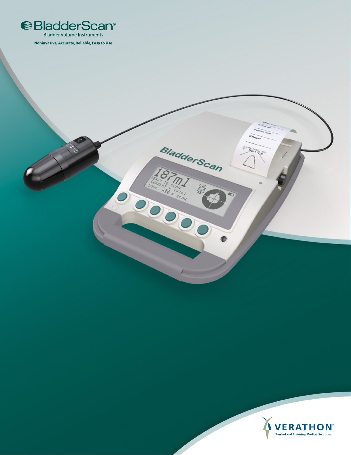
BLADDERSCAN
BVI 3000
OPERATIONS & MAINTENANCE MANUAL
Page 2

0900‑0383‑14‑60
Page 3

BLADDERSCAN
BVI 3000
OPERATIONS & MAINTENANCE MANUAL
Effective: March 6, 2015
Caution: Federal (United States) law restricts this
device to sale by or on the order of a physician.
Page 4

CONTACT INFORMATION
To obtain additional information regarding your BladderScan system,
please contact Verathon® Customer Care or visit verathon.com/contact‑us.
Corporate Headquarters:
20001 North Creek Parkway
Bothell, WA 98011 U.S.A.
800.331.2313 (US and Canada only)
425.867.1348
Fax: 425.883.2896
verathon.com
Verathon® Medical (Europe) B.V.
Linnaeusweg 11
3401 MS IJsselstein
The Netherlands
+31.30.68.70.570
Fax: +31.30.68.70.512
verathon.eu
0123
Copyright© 2014, 2015 by Verathon Inc. All rights reserved. No part of this manual may be copied or transmitted by any method
without the express written consent of Verathon Inc.
Verathon, the Verathon torch symbol, BladderScan, and the BladderScan symbol are either trademarks or registered trademarks of
Verathon Inc. All other brand and product names are trademarks or registered trademarks of their respective owners.
Information in this manual may change at any time without notice. For the most up‑to‑date information, contact Verathon Customer
Care or your local representative.
Page 5

TABLE OF CONTENTS
IMPORTANT INFORMATION ..............................................................................................................................................1
OVERVIEW ...................................................................................................................................................................... 1
Product Description .......................................................................................................................................................1
Statement of Intended Use ........................................................................................................................................... 1
Essential Performance ..................................................................................................................................................1
Statement of Prescription .............................................................................................................................................1
Notice to All Users ......................................................................................................................................................... 1
SAFETY INFORMATION ................................................................................................................................................. 2
Biological Safety ............................................................................................................................................................2
Contraindications ..........................................................................................................................................................2
Precautions & Warnings ...............................................................................................................................................2
INTRODUCTION .................................................................................................................................................................. 6
COMPONENTS & FEATURES ....................................................................................................................................... 6
Control Unit ...................................................................................................................................................................7
Scanhead ...................................................................................................................................................................... 8
Batteries & Battery Charger .......................................................................................................................................... 8
SYSTEM COMPONENTS & ACCESSORIES ................................................................................................................ 9
BUTTONS, ICONS, & CONNECTIONS ..........................................................................................................................9
Battery Icon ................................................................................................................................................................... 9
Buttons ..........................................................................................................................................................................9
SETTING UP ....................................................................................................................................................................... 10
ASSEMBLING THE INSTRUMENT .............................................................................................................................. 10
Procedure 1. Charge the Batteries .......................................................................................................................10
Procedure 2. Insert or Remove a Battery .............................................................................................................12
Procedure 3. Connect the Scanhead to the Control Unit ..................................................................................... 13
Procedure 4. Load The Thermal Paper Roll ......................................................................................................... 14
Operations & Maintenance Manual: Table of Contents
i
Page 6

CONFIGURING USER SETTINGS ...............................................................................................................................15
Procedure 1. Program the Name .......................................................................................................................... 15
Procedure 2. Set the Date ..................................................................................................................................... 17
Procedure 3. Set the Time ....................................................................................................................................19
Procedure 4. Adjust User Preferences .................................................................................................................21
USING THE INSTRUMENT ...............................................................................................................................................24
SCANNING A PATIENT .................................................................................................................................................25
Procedure 1. Measure Bladder Volume ................................................................................................................ 25
Procedure 2. Verify Aim & Accuracy .....................................................................................................................27
Procedure 3. Conrm the Scan Results ............................................................................................................... 29
MANAGING SCAN RESULTS ....................................................................................................................................... 31
Procedure 1. Add a Patient ID Number (Optional) ............................................................................................... 31
Procedure 2. Add Notes (Optional) ....................................................................................................................... 32
Procedure 3. Print the Scan Result (Optional) ......................................................................................................34
Procedure 4. Print a Histogram of Cost Savings (Optional) ................................................................................. 36
CLEANING & DISINFECTING ...........................................................................................................................................38
Procedure 1. Clean the Instrument ....................................................................................................................... 38
Procedure 2. Disinfect the Instrument ...................................................................................................................39
MAINTENANCE & TROUBLESHOOTING ....................................................................................................................... 40
ANNUAL CERTIFICATION OF CALIBRATION ............................................................................................................40
PERIODIC INSPECTIONS ............................................................................................................................................ 40
Weekly Inspections ..................................................................................................................................................... 40
Monthly Accuracy Check ............................................................................................................................................ 40
DEVICE REPAIR ............................................................................................................................................................ 40
ii
Page 7

TROUBLESHOOTING ...................................................................................................................................................41
Procedure 1. Run a Self Test ................................................................................................................................ 41
Procedure 2. Troubleshoot Power Issues ............................................................................................................. 42
Procedure 3. Troubleshoot an Error Message ...................................................................................................... 42
Procedure 4. Clear a Paper Jam ..........................................................................................................................44
Procedure 5. Test the Printer ................................................................................................................................ 45
Procedure 6. Verify Instrument Accuracy.............................................................................................................. 47
DEVICE DISPOSAL ....................................................................................................................................................... 47
WARRANTY ....................................................................................................................................................................... 48
Disclaimer of Additional Warranties ............................................................................................................................ 48
PRODUCT SPECIFICATIONS ........................................................................................................................................... 49
SAFETY & PERFORMANCE SUMMARY ....................................................................................................................49
ACCURACY RANGE ..................................................................................................................................................... 49
COMPONENT SPECIFICATIONS ................................................................................................................................ 50
Control Unit & Scanhead Specications ....................................................................................................................50
Battery Charger Specications ................................................................................................................................... 52
Battery Specications .................................................................................................................................................53
ELECTROMAGNETIC COMPATIBILITY ......................................................................................................................54
Electromagnetic Emissions.........................................................................................................................................54
Electromagnetic Immunity ..........................................................................................................................................55
Recommended Separation Distances ........................................................................................................................57
Accessory Conformance to Standards .......................................................................................................................57
SYMBOL DIRECTORY ...................................................................................................................................................... 58
GLOSSARY ........................................................................................................................................................................60
Operations & Maintenance Manual: Table of Contents
iii
Page 8

Page 9

IMPORTANT INFORMATION
OVERVIEW
PRODUCT DESCRIPTION
The BladderScan BVI 3000 is a B‑mode ultrasonic instrument, portable and battery‑operated, intended for
the noninvasive measurement of urinary bladder volume. A mechanical sector‑scanning transducer provides
cross‑sectional images of the bladder from twelve scan planes. Based on these images, the BladderScan
instrument automatically calculates the estimated bladder volume in milliliters (ml) and displays it on a screen.
STATEMENT OF INTENDED USE
The BladderScan BVI 3000 projects ultrasound energy through the lower abdomen of the nonpregnant patient
to obtain an image of the bladder, which is used to determine bladder volume noninvasively.
ESSENTIAL PERFORMANCE
Essential performance is the system performance necessary to achieve freedom from unacceptable risk. The
essential performance of the BladderScan BVI 3000 system is to produce ultrasonic output energy and display
numerical values for bladder volume. The system has a passively temperature‑controlled transducer assembly.
STATEMENT OF PRESCRIPTION
Caution: Federal (United States) law restricts this device to sale by or on the order of a physician.
NOTICE TO ALL USERS
The BladderScan BVI 3000 should be used only by individuals who have been trained and authorized by
a physician or the institution providing patient care. All operators should read this manual prior to using the
instrument. Failure to comply with these instructions may compromise the performance of the instrument.
Operations & Maintenance Manual: Important Information
1
Page 10

SAFETY INFORMATION
BIOLOGICAL SAFETY
To date, exposure to pulsed diagnostic ultrasound has not been shown to produce adverse effects. However,
ultrasound should be used only by medical professionals when clinically indicated, using the lowest exposure
times possible commensurate with clinical utility.
The ultrasonic output power of the BladderScan BVI 3000 is not user‑adjustable and is limited to the minimum
level necessary for effective performance. Data on acoustic output levels can be found in the chapter Product
Specications on page 49.
CONTRAINDICATIONS
The BladderScan BVI 3000 instrument is not intended for fetal use or for use on pregnant patients.
PRECAUTIONS & WARNINGS
Warnings indicate that injury, death, or other serious adverse reactions may result from use or misuse of the
device. Cautions indicate that use or misuse of the device may cause a problem, such as a malfunction, failure,
or damage to the product. Throughout the manual, pay attention to sections labeled Important, as these contain
reminders or summaries of the following cautions as they apply to a specic component or use situation.
To ensure safe and reliable operation for the user and patient, please heed the following warnings and cautions.
PRECAUTIONS
CAUTION
The BladderScan BVI 3000 and related devices may contain mineral oils, batteries, and other
environmentally hazardous materials. When the instrument and/or accessories have reached the
end of their useful service life, see the section Device Disposal on page 47.
CAUTION
To avoid paper jams, never fold the end of the paper roll or cut it diagonally or to a point.
CAUTION
Failure to adhere to the following when cleaning the control unit or the scanhead may result in
permanent equipment damage and void the instrument warranty:
• Ensure that you do not immerse either component in water or a cleaning or disinfecting agent.
This may permanently damage the instrument.
®
• Do not use Cidex
Plus, as it is not recommended for use with Lexan polycarbonate.
• Do not subject any part of the BVI 3000 system to steam sterilization or ethylene oxide
sterilization.
2
Page 11

CAUTION
Medical electrical equipment requires special precautions regarding electromagnetic compatibility
(EMC) and must be installed and operated according to the instructions in this manual. For more
information, see the Electromagnetic Compatibility section on page 54.
To maintain electromagnetic interference (EMI) within certied limits, the BladderScan
BVI 3000 system must be used with the cables, components, and accessories specied or
supplied by Verathon
®
. For additional information, see the System Components & Accessories
and Component Specications sections. The use of accessories and/or cables other than those
specied or supplied may result in increased emissions and/or decreased immunity of the system.
The BladderScan BVI 3000 system should not be used adjacent to or stacked with other
equipment. If adjacent or stacked use is necessary, the system should be observed to verify normal
operation in the conguration in which it will be used.
This device can radiate radio frequency energy and is very unlikely to cause harmful interference
with other devices in the vicinity. There is no guarantee that interference will not occur in a particular
installation. Evidence of interference may include degradation of performance in this device or other
devices when operated simultaneously. If this occurs, try to correct the interference by using the
following measures:
• Turn devices on and off in the vicinity to determine the source of interference
• Reorient or relocate this device or other devices
• Increase the separation between devices
• Connect the device to an outlet on a circuit different than the other device(s)
• Eliminate or reduce EMI with technical solutions (such as shielding)
• Purchase medical devices that comply with IEC 60601‑1‑2 EMC Standards
Be aware that portable and mobile radio frequency communications equipment (cellular phones,
etc.) may affect medical electrical equipment; take appropriate precautions during operation.
WARNINGS
WARNING
Do not use the BladderScan BVI 3000 instrument on:
• A patient who has open skin or wounds in the suprapubic area.
• A patient with ascites.
• A pregnant patient.
WARNING
Risk of explosion. If you use the BladderScan BVI 3000 instrument in the presence of ammable
anesthetics, the hazard of potential explosion exists.
Operations & Maintenance Manual: Important Information
3
Page 12
WARNING
When using the instrument, be aware of the following conditions that can affect ultrasound
transmission and decrease the accuracy of exam results:
• Abdominal Surgery— Scar tissue, surgical incisions, sutures, and staples can affect ultrasound
transmission and accuracy. Use care when scanning patients who have had abdominal surgery
• Catheterization—A catheter in the patient’s bladder may affect the accuracy of the bladder
volume measurement; however, the volume measurement may still be clinically useful if it is
large (detecting a blocked catheter, for example).
• Obesity—Obesity may affect bladder volume measurements. Lift as much abdominal adipose
tissue out of the way of the instrument as possible. Apply more pressure to the scanhead to
reduce the amount of adipose tissue through which the ultrasound must pass.
Accuracy is compromised if you do not obtain an optimal, repeatable image.
WARNING
Electric shock hazard. Do not attempt to open the system components. This may cause serious
injury to the operator or damage to the instrument and will void the warranty. Contact Verathon
Customer Care for all servicing needs.
WARNING
Risk of electric shock or burns. Do not use the BladderScan instrument in conjunction with
high‑frequency surgical equipment.
WARNING
This product may only be cleaned and disinfected by using the approved processes provided in
this manual. Cleaning and disinfection methods listed are recommended by Verathon
®
based on
compatibility with component materials.
WARNING
Availability of cleaning and disinfection products varies by country, and Verathon is unable
to test products in every market. For more information, please contact Verathon Customer
Care at 1.800.331.2313 or your local representative. For additional contact information, visit
verathon.com/contact‑us.
WARNING
Ensure that you follow the manufacturer’s instructions for handling and disposing of the cleaning
and disinfection solutions provided in this manual.
4
Page 13
WARNING
Cleaning is critical to ensuring the component is ready for disinfection. Failure to properly clean the
device could result in a contaminated instrument after completing the disinfection procedure.
WARNING
In order to maintain electrical safety, use only the provided medical‑approved power supply, battery
charger, and batteries.
WARNING
To reduce the risk of electrical shock, use only the accessories and peripherals recommended by
Verathon
®
.
WARNING
No modication of this equipment is allowed.
WARNING
The battery charger, power supply, and power cables are not intended for patient contact. Ensure
six feet (two meters) is maintained between the patient and these components.
WARNING
Risk of explosion, re, or serious injury. The BladderScan BVI 3000 system is battery‑powered.
Failure to note the following when handling the battery may result in serious injury or damage:
• Never short‑circuit the battery by bringing the battery terminals into contact with any other
conductive object.
• Never expose the battery to abnormal shock, vibration, or pressure.
• Do not disassemble, heat above 60°C (140°F), or incinerate the battery.
• Keep battery out of reach of children and in original package until ready to use.
• If the battery is leaking or its case is cracked, put on protective gloves to handle it, and discard
it immediately. Always dispose of used batteries in compliance with all applicable laws and
regulations.
• Put insulating tape, such as cellophane tape, on the electrodes during transportation in order to
avoid a possible short circuit, re, or electrical shock.
Operations & Maintenance Manual: Important Information
5
Page 14
INTRODUCTION
COMPONENTS & FEATURES
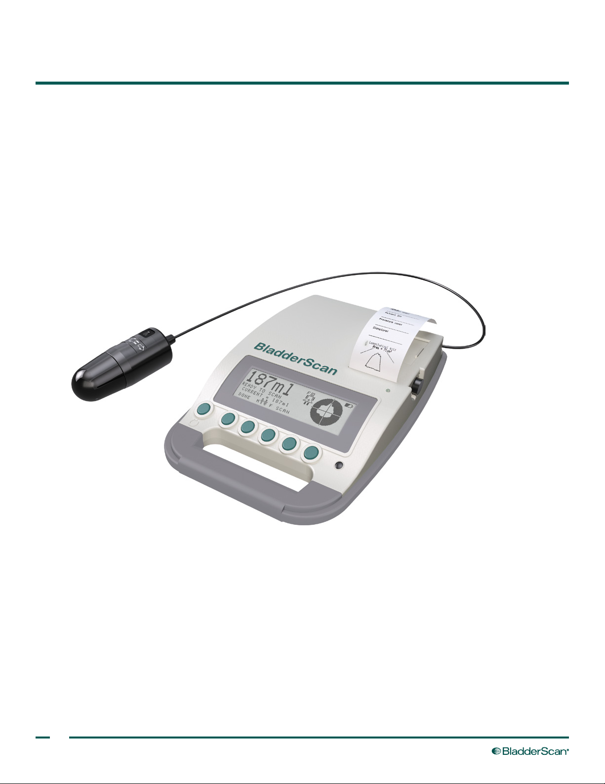
The BladderScan BVI 3000 consists of four main components: the scanhead, the control unit, rechargeable
batteries, and the battery charger. In addition, you may purchase optional accessories and additional supplies
such as ultrasound gel, thermal paper for the printer, a mobile cart, or a carrying case. For more information
about available accessories, see System Components & Accessories on page 9 or contact Verathon®.
This section describes the main components and their parts and features.
Figure 1. BladderScan BVI 3000 Control Unit and Scanhead
6
Page 15
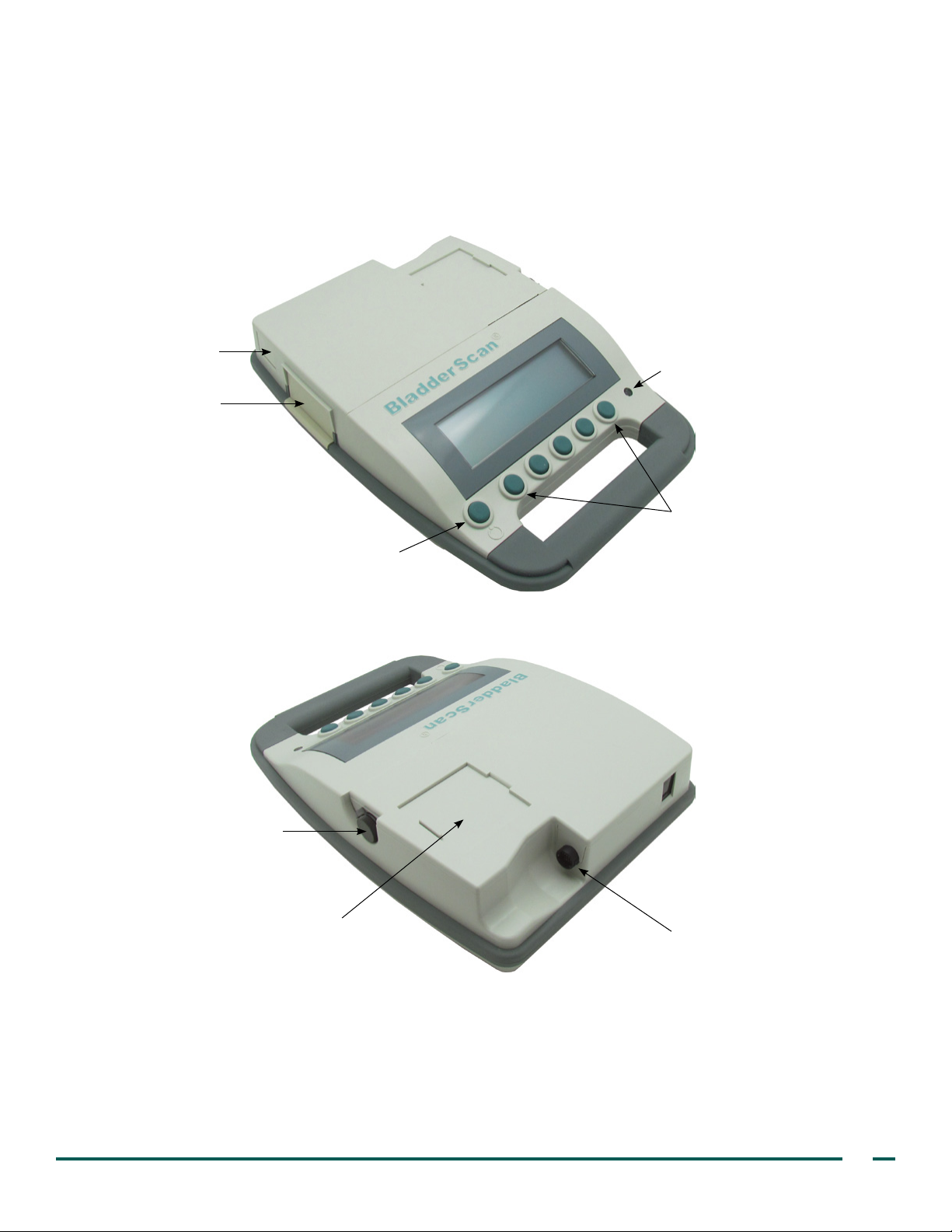
CONTROL UNIT
The control unit provides all operating controls for the scanning procedure by means of six buttons. The
measured bladder volume and a target‑shaped aiming icon are clearly displayed on the LCD screen, helping the
operator to achieve accurate measurement results.
Figure 2. Control Unit Components
Battery‑eject button
Battery
Light sensor
Function buttons (5)
Printhead release lever and
manual paper‑feed wheel
Power button
Paper well
Scanhead cable port
Operations & Maintenance Manual: Introduction
7
Page 16
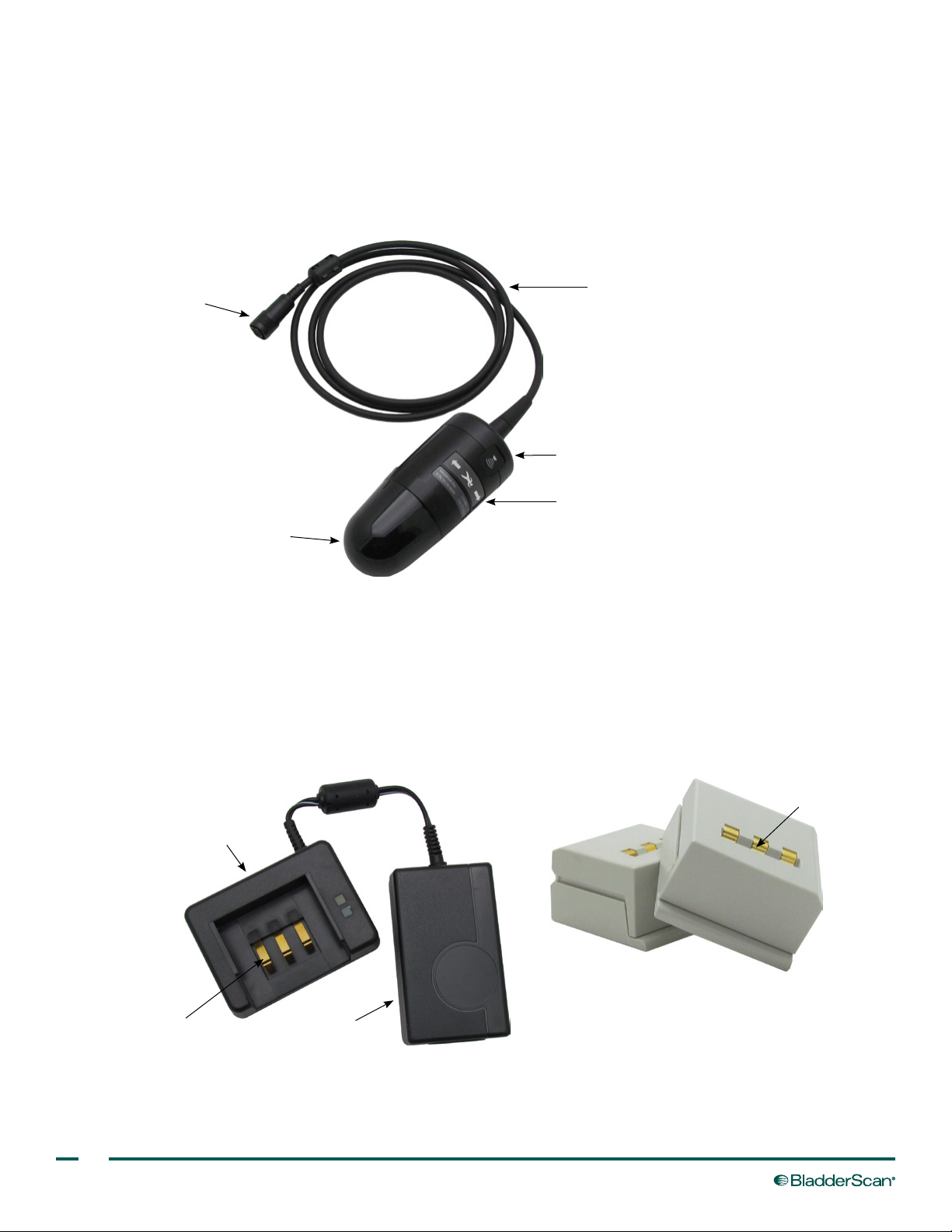
SCANHEAD
The scanhead transmits and receives ultrasound, automatically moving its internal transducer 360º to scan
twelve planes and produce a three‑dimensional image of the urinary bladder. The scanhead is connected to the
control unit by means of a cable.
Figure 3. Scanhead Components
Cable connector
Cable
Scan button
Patient orientation icon
Dome
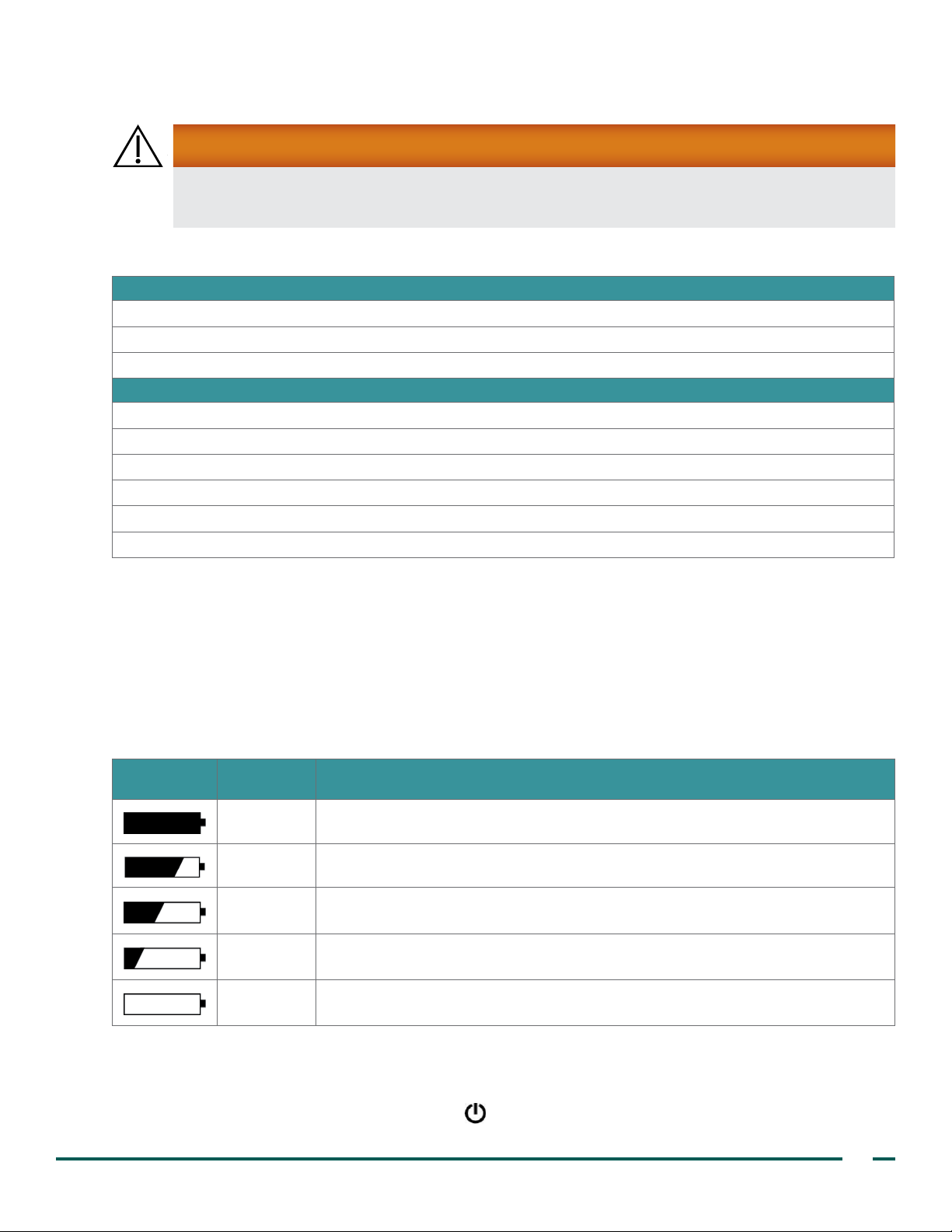
BATTERIES & BATTERY CHARGER
Two NiMH rechargeable batteries are included with the BladderScan BVI 3000. One battery can be recharged in
the battery charger while the other is being used to power the BVI 3000. This ensures that there is no instrument
downtime due to battery charge.
Figure 4. Battery Charger
Battery charger
Battery contacts
Power adapter
Figure 5. Rechargeable Batteries (2)
Battery contacts
8
Page 17
SYSTEM COMPONENTS & ACCESSORIES
WARNING
To reduce the risk of electrical shock, use only the accessories and peripherals recommended by
Verathon
Table 1. Components & Accessories
BladderScan BVI 3000 control unit
BladderScan BVI 3000 scanhead
BladderScan BVI 3000 battery charger
Battery, 7.2 volt (V), 2 provided
Printer paper
BladderScan BVI 3000 In‑Service CD, containing the operations & maintenance manual and a video tutorial
Acoustic coupling gel
Carrying case (Optional)
Mobile cart (Optional)
®
.
COMPONENTS
ACCESSORIES
BUTTONS, ICONS, & CONNECTIONS
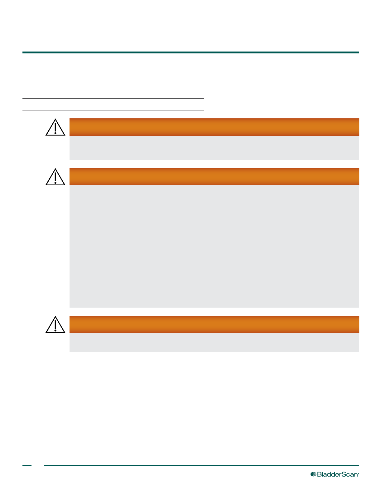
BATTERY ICON
The battery icon, located in the upper‑right corner of the LCD, indicates the power status of the battery currently
installed in your instrument.
Table 2. Battery Icons
ICON STATUS
BUTTONS
The ve buttons below the LCD screen change functions based on the content currently displayed on the
screen. The button marked with the power symbol turns the BVI 3000 control unit on or off.
PERCENT
REMAINING
100% A fully darkened battery icon indicates that the battery is fully charged and ready for use.
75% A battery icon that is almost full indicates a partially discharged battery.
50%
25%
0%
When the battery icon is half‑darkened, the battery is partially discharged. This is
the most common display, shown during the majority of the battery’s charge life.
An almost empty battery icon indicates that the battery is nearly discharged. While a
few more scans can still be performed, the battery should be replaced at this point.
When the battery is fully discharged, the battery icon is completely clear and the
BVI 3000 does not work. The discharged battery must be replaced with a charged one.
DESCRIPTION
Operations & Maintenance Manual: Introduction
9
Page 18
SETTING UP
ASSEMBLING THE INSTRUMENT
PROCEDURE 1. CHARGE THE BATTERIES
WARNING
The battery charger, power supply, and power cables are not intended for patient contact. Ensure
six feet (two meters) is maintained between the patient and these components.
WARNING
Risk of explosion, re, or serious injury. The BladderScan BVI 3000 system is battery‑powered.
Failure to note the following when handling the battery may result in serious injury or damage:
• Never short‑circuit the battery by bringing the battery terminals into contact with any other
conductive object.
• Never expose the battery to abnormal shock, vibration, or pressure.
• Do not disassemble, heat above 60°C (140°F), or incinerate the battery.
• Keep battery out of reach of children and in original package until ready to use.
• If the battery is leaking or its case is cracked, put on protective gloves to handle it, and discard
it immediately. Always dispose of used batteries in compliance with all applicable laws and
regulations.
• Put insulating tape, such as cellophane tape, on the electrodes during transportation in order to
avoid a possible short circuit, re, or electrical shock.
WARNING
In order to maintain electrical safety, use only the provided battery charger and batteries.
The BladderScan BVI 3000 draws very little power when it is turned off; however, if you do not plan to use your
instrument for several weeks, you should remove the battery to prevent it from discharging.
The battery that is not in use should be stored in the charger so that it remains fully charged. There is no danger
of overcharging the battery.
1. To maintain accessibility, plug in the charger only where it can be easily unplugged.
10
Page 19
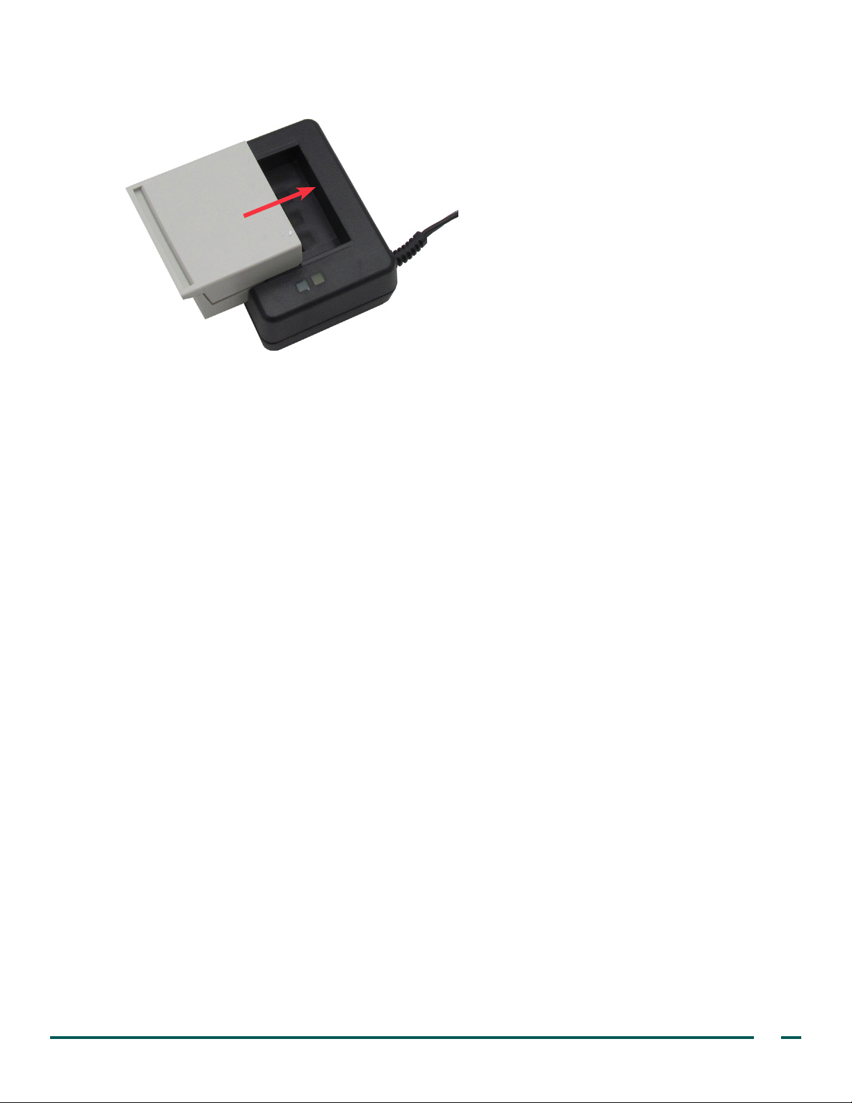
2. Align the battery as shown in the following gure, and then slide the battery into the recess on the top of
the charger.
3. Monitor the color indicator lights on top of the battery charger in order to determine the battery’s
charging status:
• Solid Green—When the battery is low on charge, charging begins in the fast‑charge mode. During
fast‑charge mode, the green light is solid. For a fully discharged battery, fast‑charge mode lasts about
two to three hours.
• Quickly Flashing Green—When the battery reaches 80% of its charge level, the charger starts to
“top off” the charge, and the green light ashes quickly. At this point, you may use the battery in the
BVI 3000 instrument.
• Slowly Flashing Green—If the green light ashes slowly upon inserting a battery, then the battery level
is too low for fast‑charge mode. The charger slowly charges the battery until the power level is high
enough to begin fast‑charge mode. When the battery power level is high enough, fast‑charge mode
begins automatically.
• Solid Amber—The amber light indicates that the battery temperature is stabilizing before recharging can
begin. This may occur when the battery is taken from a very cold or warm environment, or if the battery is
defective. If the light remains amber for over an hour, the battery is defective and must be replaced.
Operations & Maintenance Manual: Setting Up
11
Page 20
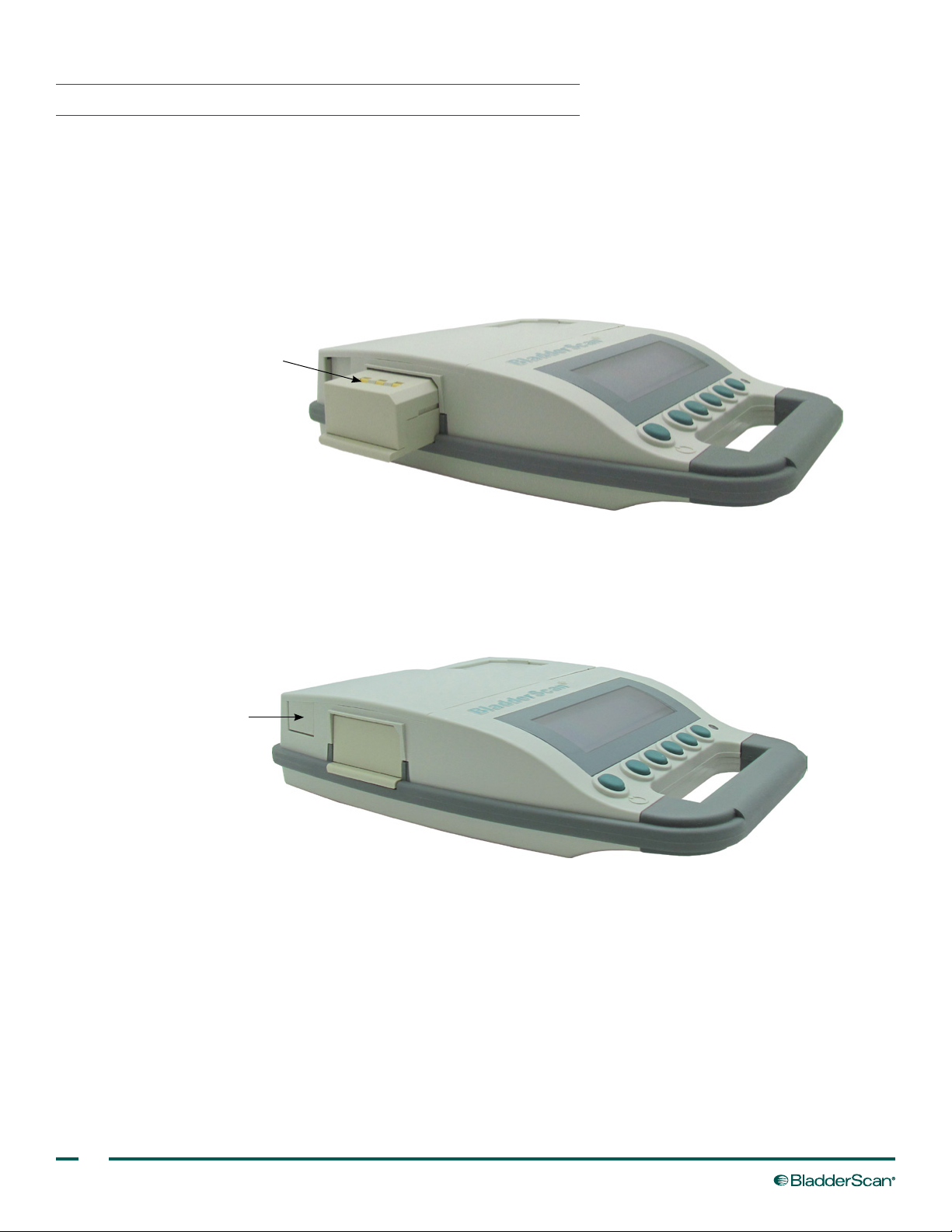
PROCEDURE 2. INSERT OR REMOVE A BATTERY
INSERT A BATTERY
1. Ensure the battery has been properly charged according to the instructions in the procedure Charge the
Batteries on page 10.
2. If a battery is already in the control unit, remove it according to the instructions in the following section
Remove a Battery.
3. Align the charged battery with the battery well as shown in the following gure.
Battery contacts facing up
4. Slide the battery into the well and press until the battery clicks into place.
REMOVE A BATTERY
1. Next to the battery well, press the battery‑eject button. The battery is released from the control unit.
Battery‑eject button
2. Slide the battery out of the control unit.
3. Recharge or store the removed battery in the charger according to the instructions in the procedure Charge
the Batteries on page 10.
12
Page 21
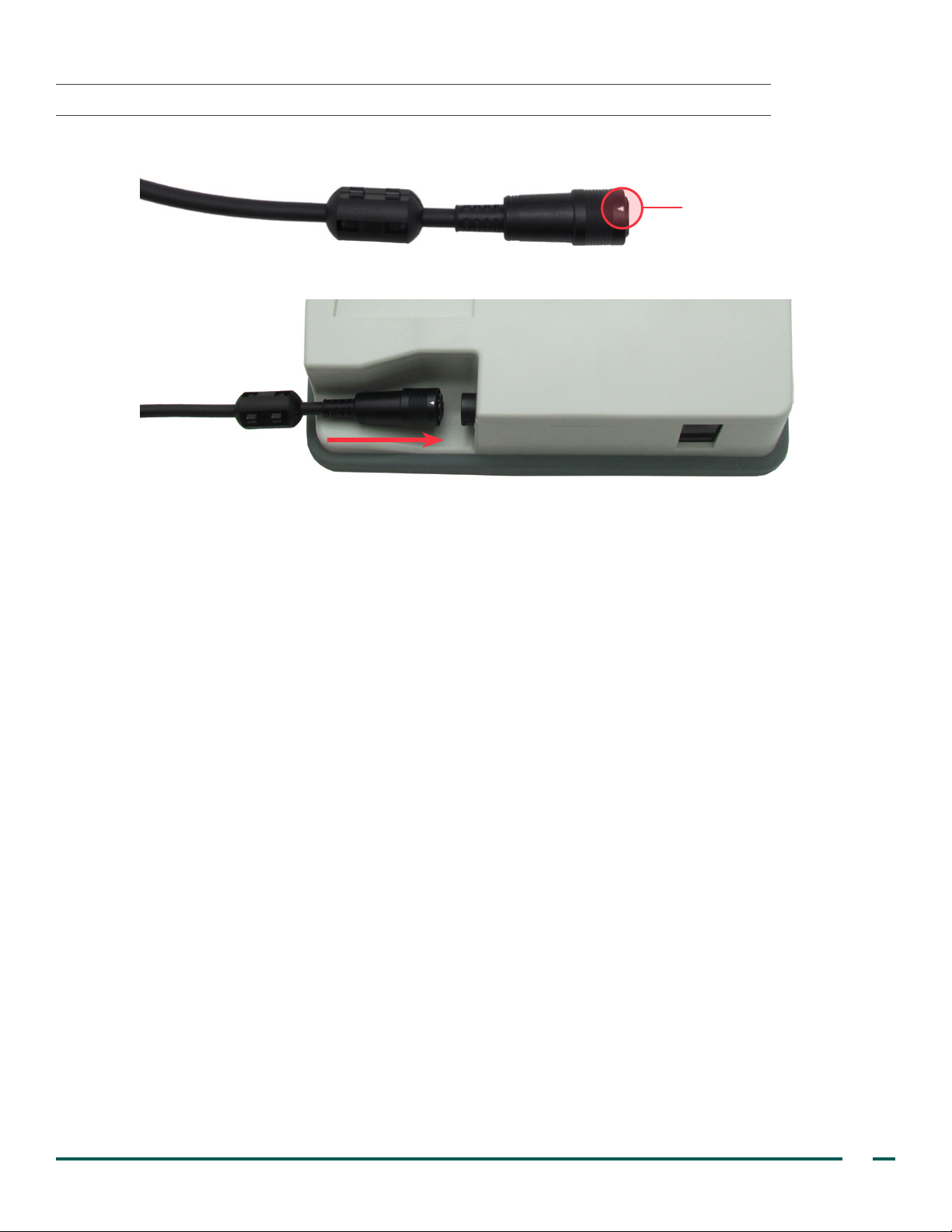
PROCEDURE 3. CONNECT THE SCANHEAD TO THE CONTROL UNIT
1. Align the scanhead cable connector so that the arrow is facing up.
Arrow on scanhead
cable connector
2. Press the connector directly into the port until you hear a click.
3. If you want to disconnect the scanhead from the control unit, grip the black plastic ring on the cable
connector, and then pull straight out. Do not twist the cable or connector.
Operations & Maintenance Manual: Setting Up
13
Page 22
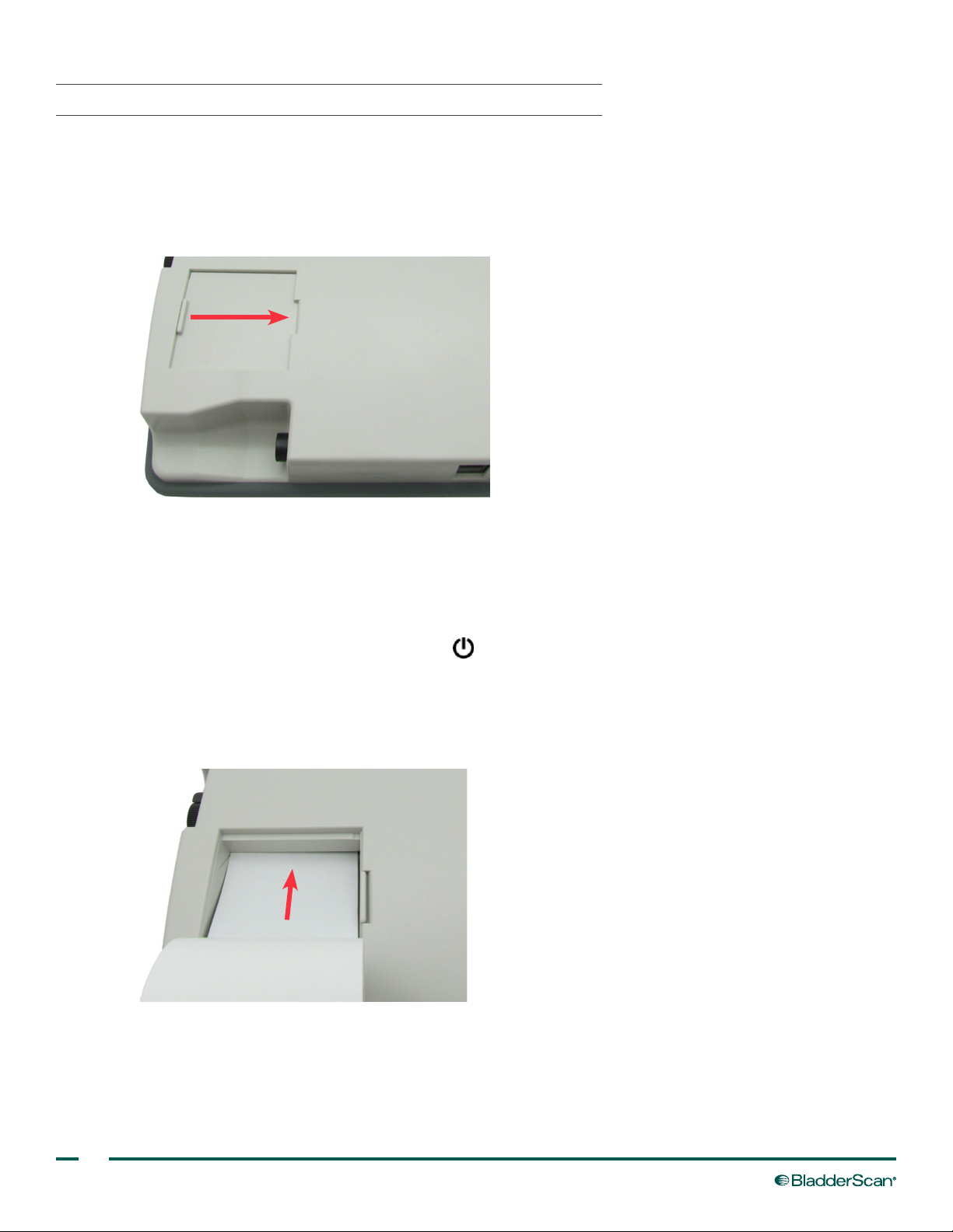
PROCEDURE 4. LOAD THE THERMAL PAPER ROLL
If the instrument is experiencing a paper jam, see the procedure Clear a Paper Jam on page 44.
The BladderScan BVI 3000 has an automatic paper‑loading mechanism. When you insert the paper roll
correctly, the instrument automatically feeds the paper through the instrument and prepares for printing.
1. On the top of the control unit, open the paper well door.
2. If there is an empty paper roll in the paper well, remove it.
3. If you are loading a new paper roll, cut off the rst inch of the new paper.
4. Ensure that the end of the paper roll is cut straight. Do not fold the end of the paper roll, cut it diagonally, or
cut it to a point.
5. Turn the BVI 3000 on by pressing the power button.
6. Insert the end of a new paper roll, with the thermal side down, into the paper input slot. The
BVI 3000 senses the presence of the paper and automatically feeds the paper through the instrument.
Note: To verify that you are loading the paper with the thermal side down, ick your nail over the paper. If a
black mark appears, this is the thermal side.
7. Place the paper roll in the paper well.
8. Close the paper well door. The instrument is ready to print.
14
Page 23
CONFIGURING USER SETTINGS
PROCEDURE 1. PROGRAM THE NAME
You can customize the BladderScan BVI 3000 instrument by entering your facility or provider name. This
information is subsequently included on all printouts of exam results.
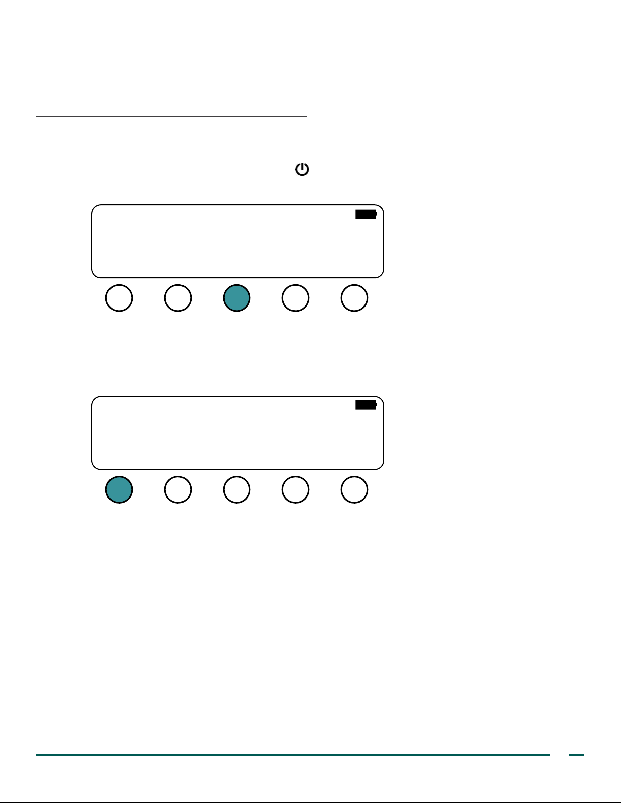
1. Turn the BVI 3000 on by pressing the power button.
2. On the Main Menu screen, press the A LT button.
BVI 3000
SCAN ALTPRINT NOTES
3. If you are prompted, enter your PIN code.
Note: The default PIN code is 0000. For information about how to change the PIN code, see the procedure
Adjust User Preferences on page 21.
13:2705/22/14
4. On the Alternate Menu screen, press the NAME button.
VER: 3.020 (D949)
Box ID: 00001965
Copyright 2013 by
VERATHON Corporation
NAME TIMEDATE
PREF
SELF
TEST
Operations & Maintenance Manual: Setting Up
15
Page 24
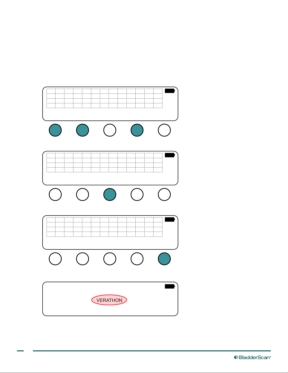
5. On the Name Preset screen, use the right and down buttons in order to highlight the
character that you would like to enter, and then press the SEL button. The character is added to the
name below the character grid. Repeat as necessary in order to enter the desired name.
Note the following:
• When the cursor reaches the right or bottom edge of the grid, it wraps around to the left or top edge.
• You may use any combination of up to 27 characters when entering the facility name.
• If you would like to enter a space, select any empty character, and then press the SEL button.
• When the right or down buttons are pressed and held, the cursor moves one character per second.
A
B
C
D
E
F
G
H
I
J
N
O
P
Q
R
S
T
U
V
W
0
1
2
3
4
5
6
7
8
#
(
)
-
;
:
&
.
9
,
’
LYM
K
X
/
Z
VERATHON_
ERASE
SELDONE
6. If you would like to delete a character, press the ERASE button. This deletes the last character entered.
A
B
C
D
E
F
G
H
I
J
N
O
P
Q
R
S
T
U
V
W
0
1
2
3
4
5
6
7
8
#
(
)
-
;
:
&
.
9
,
’
LYM
K
X
/
Z
VERATHON_
ERASE
SELDONE
7. When you are nished entering the name, press the DONE button.
A
B
C
D
E
F
G
H
I
J
N
O
P
Q
R
S
T
U
V
W
0
1
2
3
4
5
6
7
8
#
(
)
-
;
:
&
.
9
,
’
LYM
K
X
/
Z
VERATHON_
ERASE
SELDONE
16
The name you entered is now displayed on the Main Menu screen.
BVI 3000
VERATHON
13:2705/22/14
SCAN ALT
PRINT NOTES
Page 25
PROCEDURE 2. SET THE DATE
Once set, the BVI 3000 clock recognizes the number of days in each month, including February during leap
years. It has its own lithium battery and maintains the correct date and time for at least ten years, even if the
rechargeable battery is removed.
This procedure uses the month/day/year format for the date setting. If you would like to change the date format,
see the procedure Adjust User Preferences on page 21.
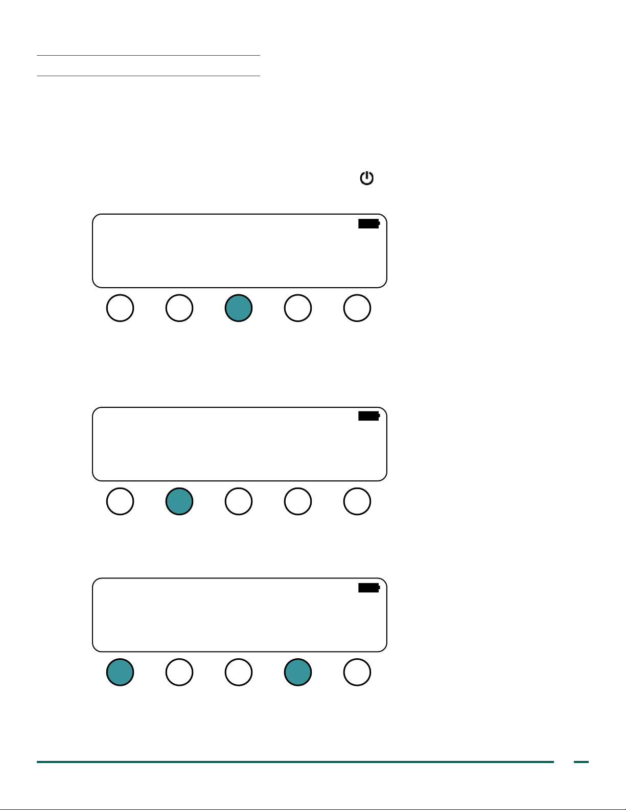
1. Turn the BladderScan BVI 3000 on by pressing the power button.
2. On the Main Menu screen, press the A LT button.
BVI 3000
VERATHON
SCAN ALT
3. If you are prompted, enter your PIN code.
Note: The default PIN code is 0000. For information about how to change the PIN code, see the procedure
Adjust User Preferences on page 21.
13:2705/22/14
PRINT NOTES
4. On the Alternate Menu screen, press the DATE button.
VER: 3.020 (D949)
Box ID: 00001965
Copyright 2013 by
VERATHON Corporation
NAME TIMEDATE
5. On the Date Preset screen, press the
number, and then press the MM button until the correct month is displayed.
Note: Only values from 01 to 12 are allowed.
PREF
button to toggle between increasing or decreasing the month
SELF
TEST
05/22/14
MM
DD
YY
DONE
Operations & Maintenance Manual: Setting Up
17
Page 26
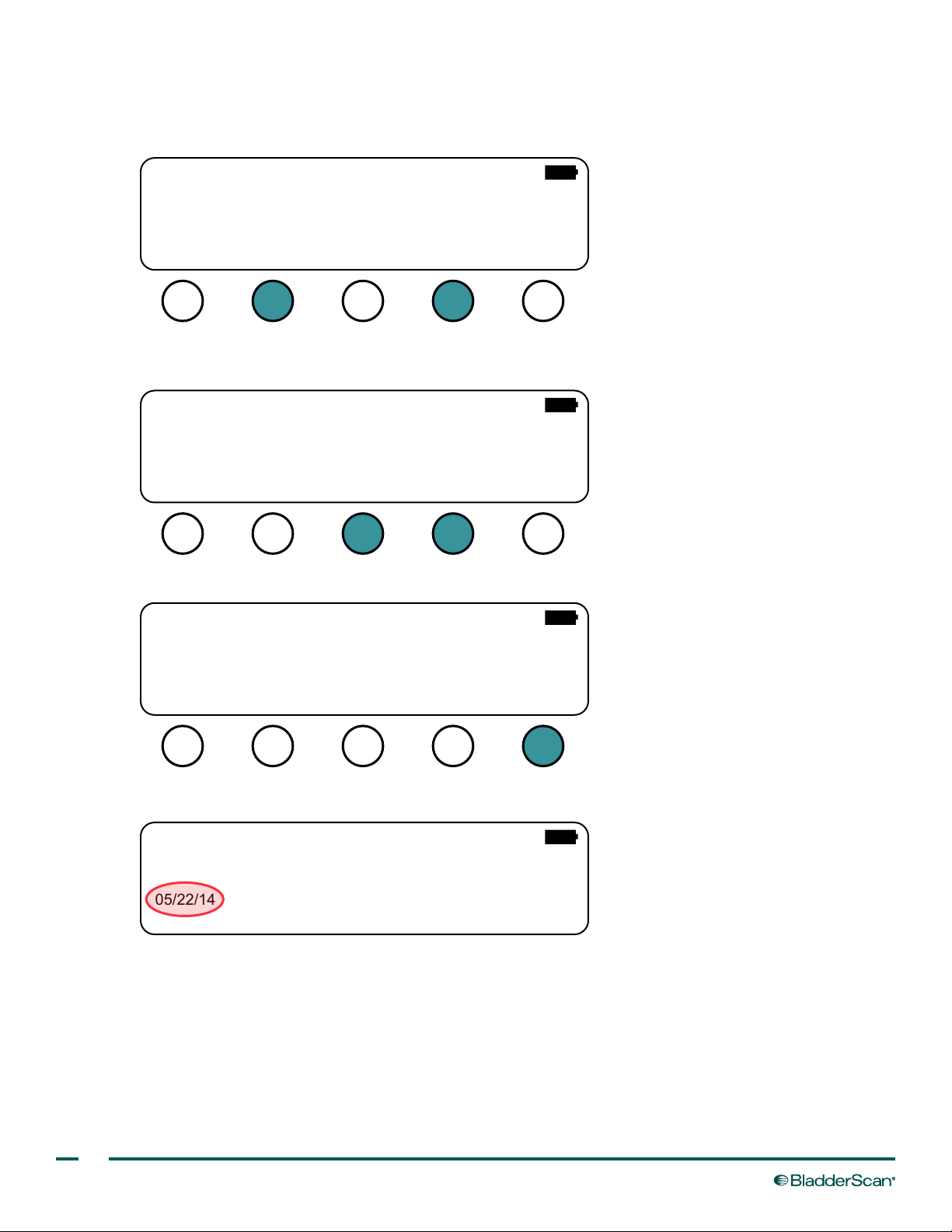
6. Press the
until the correct day is displayed.
Note: Only values from 01 to 31 are allowed.
button to toggle between increasing or decreasing the day, and then press the DD button
05/22/14
MM
7. Press the
until the correct year is displayed.
DD
button to toggle between increasing or decreasing the year, and then press the YY button
YY
DONE
05/22/14
MM
8. When you are nished entering the date, press the DONE button.
DD
YY
DONE
05/22/14
MM
DD
YY
DONE
18
The date you entered is now displayed on the Main Menu screen.
BVI 3000
VERATHON
13:2705/22/14
SCAN ALT
PRINT NOTES
Page 27
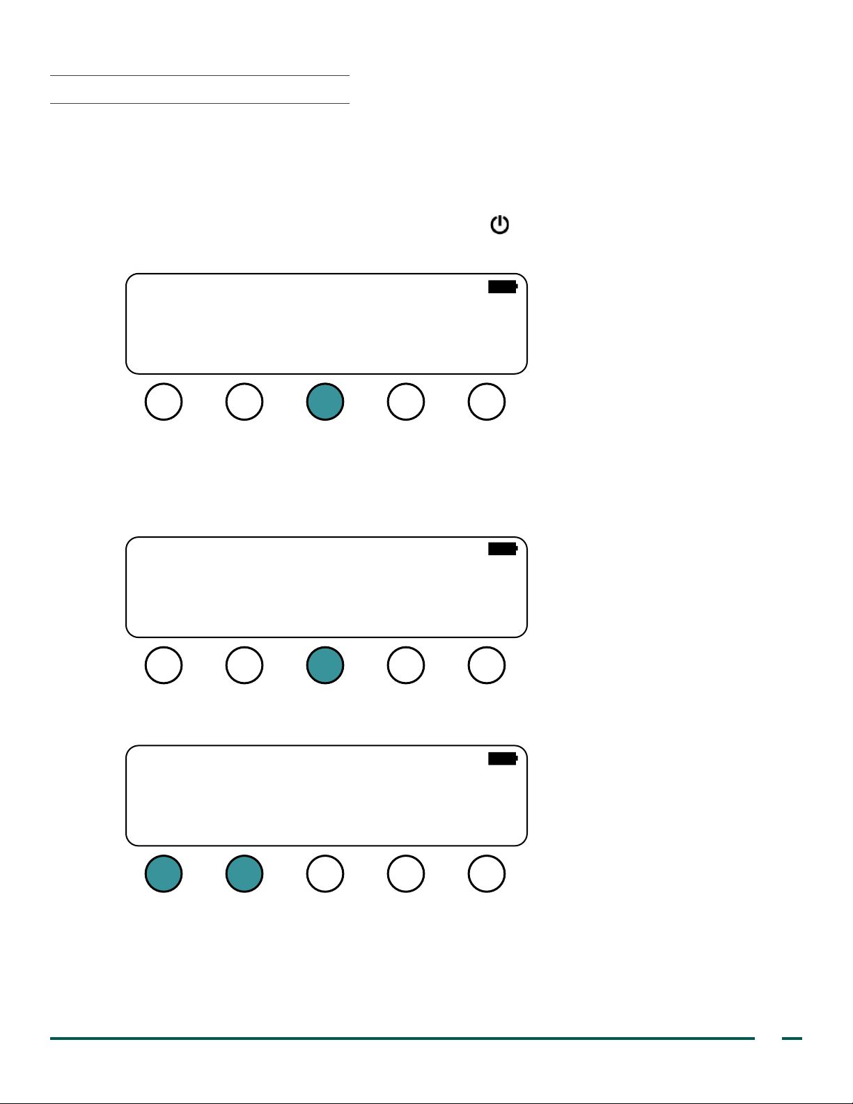
PROCEDURE 3. SET THE TIME
The internal clock is accurate to better than one minute per month at 25°C (77°F). It will operate for at least
10 years from an internal lithium battery. Enter the time in 24‑hour format (also known as military time).
To convert 12‑hour clock time to 24‑hour format, if the time is after noon, add 12 hours to the clock time
(Example: 3:00 PM + 12 hours = 15:00).
1. Turn the BladderScan BVI 3000 on by pressing the power button.
2. On the Main Menu screen, press the A LT button.
BVI 3000
VERATHON
SCAN ALT
3. If you are prompted, enter your PIN code.
Note: The default PIN code is 0000. For information about how to change the PIN code, see the procedure
Adjust User Preferences on page 21.
13:2705/22/14
PRINT NOTES
4. On the Alternate Menu screen, press the TIME button.
VER: 3.020 (D949)
Box ID: 00001965
Copyright 2013 by
VERATHON Corporation
NAME TIMEDATE
5. On the Time Preset screen, press the HH button to decrease the hour value, or press the HH button to
increase the hour value.
PREF
SELF
TEST
13:27
HH
HH
MM
MM
DONE
Operations & Maintenance Manual: Setting Up
19
Page 28
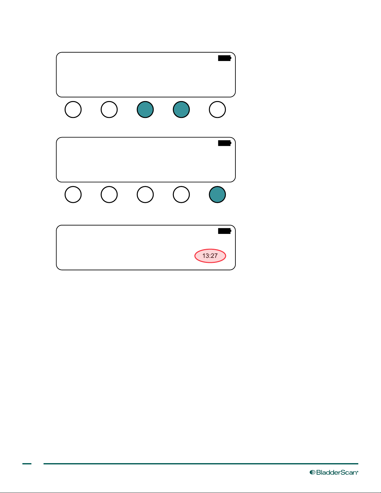
6. Press the MM button to decrease the minute value, or press the MM button to increase the minute
BVI 3000
value.
13:27
HH
7. When you are nished entering the time, press the DONE button.
HH
MM
MM
DONE
13:27
HH
The time you entered is now displayed on the Main Menu screen.
SCAN ALT
HH
MM
VERATHON
MM
PRINT NOTES
DONE
13:2705/22/14
20
Page 29

PROCEDURE 4. ADJUST USER PREFERENCES
On the Preference screen, various BVI 3000 operating parameters can be customized for personalized use. The
following table documents the congurable parameters and their available values.
Table 3. User Preferences
PARAMETER RANGE OR VALUE DESCRIPTION
AUTO (default)
Backlight
Beep volume 0–9 (default is 5)
Language
Date
Printout
Quick
UTI rate 0–100% (default is 3%)
UTI cost 0‑2000 (default is 680) Cost to treat a UTI; used in cost‑savings calculations
Cath cost 0–20 (default is 3) Cost of a catheter; used in cost‑savings calculations
Cath vol
Flash
Time zone GMT ± 0–12 (default is 0) This function is currently not used
Multiple languages
ADD_WALLS (default)
0–1000 ml (default is 300
ON The backlight is always on
OFF The backlight is always off
available
MM/DD/YY Month, day, year
DD/MM/YY Day, month, year
YY/MM/DD Year, month, day
NO_IMAGES Do not print any B‑mode images
RAW_ONLY
WALLS_ONLY Bladder outline only
12_PLANES All 12 scan planes, printed as in the ADD_WALLS mode
OFF (default)
ON
ml)
OFF (default)
ON
The backlight turns on and off automatically, depending
on the ambient light conditions
Adjusts the instrument volume level up (higher values) or
down (lower values)
Species the language used for displays and printouts
Print grayscale, B‑mode images with bladder walls
highlighted
Print grayscale B‑mode images without identifying the
bladder walls
When you press the PRINT button, the Print screen
appears, and you may select whether you would like to
print the last scan result, cost savings, or a test print.
When you are on the Scan Results screen, if you press
the PRINT button, the scan results print automatically (the
Print screen does not appear).
Percentage of catheterizations that result in UTI; used in
cost‑savings calculations
Bladder volume below which catheterization is
unnecessary; used in cost‑savings calculations
Scan results are not saved if instrument is turned off;
however, processing time is slightly faster
Flash memory is enabled, and scan results are saved
even the instrument turns off
Operations & Maintenance Manual: Setting Up
21
Page 30
PARAMETER RANGE OR VALUE DESCRIPTION
Adjust display contrast ratio; the higher the value, the
darker the background
Contrast Adjust 30–63 (default is 57)
$ Set the currency for calculating cost savings to dollars
€ Set the currency for calculating cost savings to euros
Currency
₤ Set the currency for calculating cost savings to pounds
¥ Set the currency for calculating cost savings to yen
Note: An immediate effect is seen only when adjusting the
contrast up. Adjusting the contrast down becomes visible
when the instrument is turned off and on again.
Reset the user‑controllable scan counter to zero.
Scan count screen —
Reset histogram —
Change PIN code —
IMPORTANT
If you change the PIN code, ensure that you record or remember it. If your existing PIN code is lost or
forgotten, you must contact Verathon
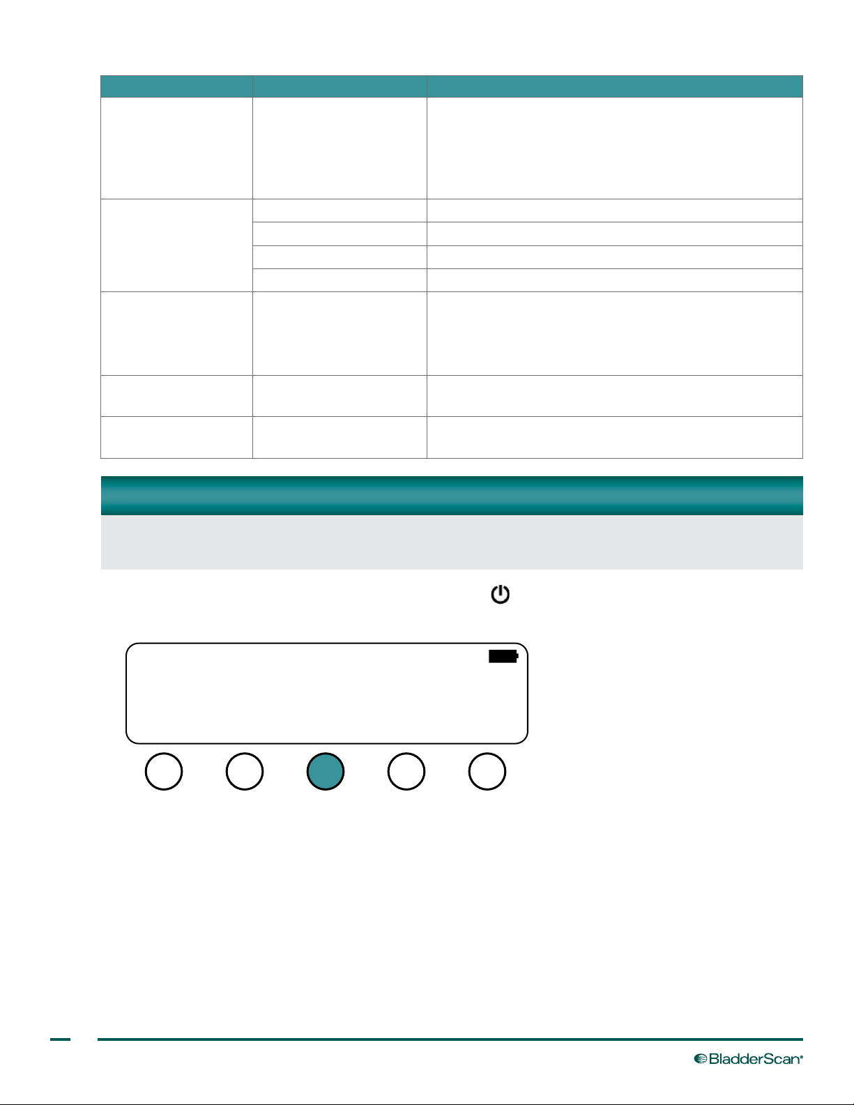
1. Turn the BladderScan BVI 3000 on by pressing the power button.
2. On the Main Menu screen, press the A LT button.
®
Customer Care in order to reset it.
Note: There are two scan counters in the BVI 3000. One
may be reset by users, and the other may only be reset
by an authorized Verathon representative.
Reset the histogram to being a new analysis of cost
savings
Change the PIN code. The current PIN is displayed. Enter
the desired PIN, and then press DONE.
BVI 3000
VERATHON
13:2705/22/14
SCAN ALT
PRINT NOTES
3. If you are prompted, enter your PIN code.
Note: The default PIN code is 0000.
22
Page 31
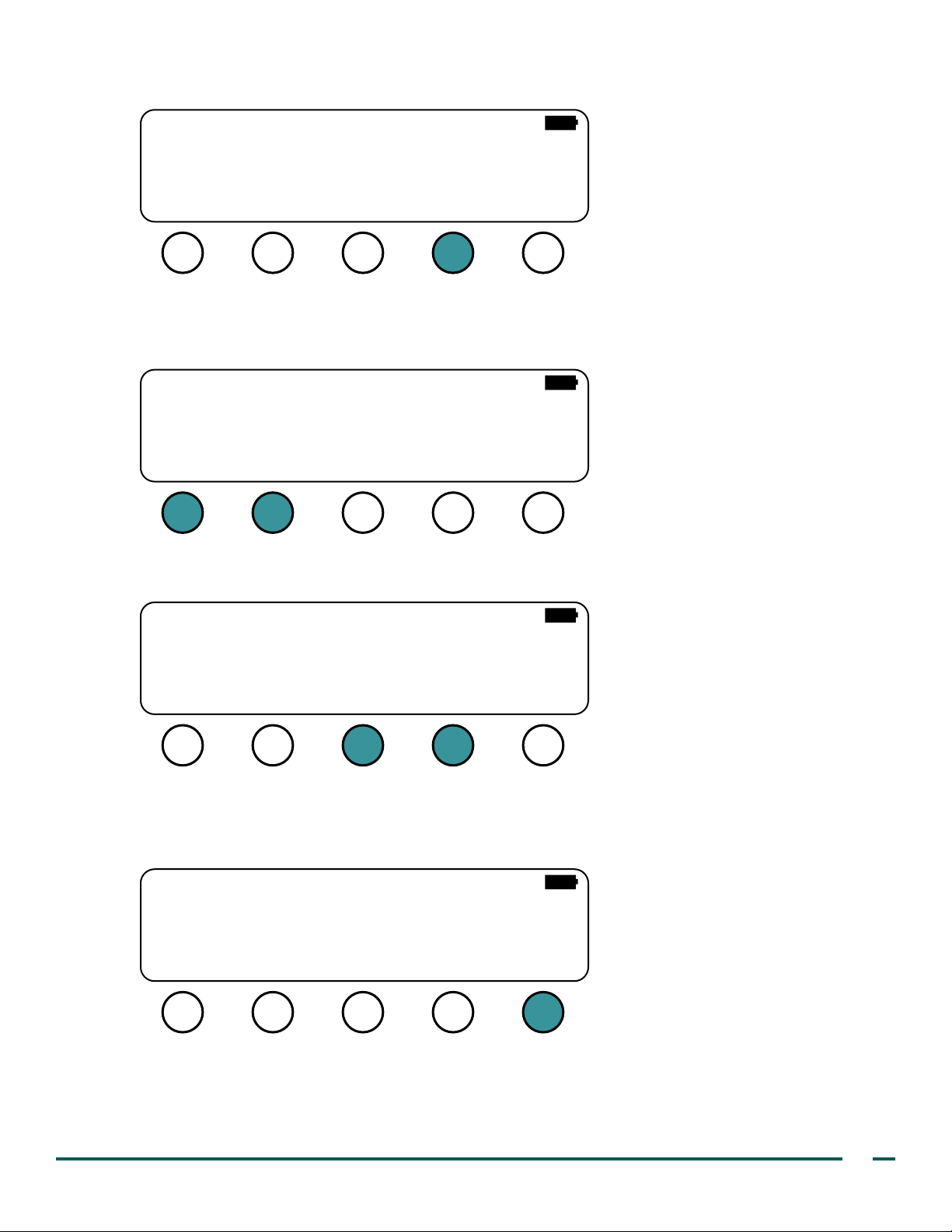
4. On the Alternate Menu screen, press the PREF button.
–D
–D
–D
VER: 3.020 (D949)
Box ID: 00001965
Copyright 2013 by
VERATHON Corporation
SELF
NAME TIMEDATE
PREF
TEST
5. On the Preferences screen, select the parameter that you wish to adjust by using the SEL and SEL
buttons.
Note: Continue pressing the SEL button in order to view additional parameters in the list.
Backlight=AUTO
Beep volume=1
Language=ENGLISH
Date=MM/DD/YY
Printout=WALLS ONLY
SEL
+SEL
ONE
6. When you have selected the parameter you wish to adjust, change the parameter value by pressing the
plus + or minus – buttons.
Backlight=AUTO
Beep volume=1
Language=ENGLISH
Date=MM/DD/YY
Printout=WALLS ONLY
SEL
+SEL
ONE
7. Repeat Step 5 through Step 6 as needed to adjust desired preferences.
8. When you are nished adjusting preferences, press the DONE button. Your preferences are saved, and the
instrument returns to the Main Menu screen.
Backlight=AUTO
Beep volume=1
Language=ENGLISH
Date=MM/DD/YY
Printout=WALLS ONLY
SEL
+SEL
Operations & Maintenance Manual: Setting Up
ONE
23
Page 32
USING THE INSTRUMENT
WARNING
Risk of explosion. If you use the BladderScan BVI 3000 instrument in the presence of ammable
anesthetics, the hazard of potential explosion exists.
WARNING
Risk of electric shock or burns. Do not use the BladderScan instrument in conjunction with HF
surgical equipment.
WARNING
When using the instrument, be aware of the following conditions that can affect ultrasound
transmission and decrease the accuracy of exam results.
• Abdominal Surgery— Scar tissue, surgical incisions, sutures, and staples can affect ultrasound
transmission and accuracy. Use care when scanning patients who have had abdominal surgery
• Catheterization—A catheter in the patient’s bladder may affect the accuracy of the bladder
volume measurement; however, the volume measurement may still be clinically useful if it is
large (detecting a blocked catheter, for example).
• Obesity—Obesity may affect bladder volume measurements. Lift as much abdominal adipose
tissue out of the way of the instrument as possible. Apply more pressure to the scanhead to
reduce the amount of adipose tissue through which the ultrasound must pass.
Accuracy is compromised if you do not obtain an optimal, repeatable image.
WARNING
Do not use the BladderScan BVI 3000 instrument on:
• A patient who has open skin or wounds in the suprapubic area.
• A patient with ascites.
• A pregnant patient.
24
Page 33
SCANNING A PATIENT
Verathon® advises new operators to use the BladderScan BVI 3000 on patients with moderately full bladders,
rather than initially attempting to locate nearly empty bladders. An in‑service training video has been supplied
with your instrument. It is recommended that you view the video as a supplement to the procedures provided in
this manual.
PROCEDURE 1. MEASURE BLADDER VOLUME
1. Ensure the instrument has been properly cleaned according to the instructions in the Cleaning & Disinfecting
chapter on page 38.
2. Ensure that the battery is sufciently charged. If necessary, recharge or replace the battery.
3. Turn the BladderScan BVI 3000 on by pressing the power button.
4. On the Main Menu screen, press the SCAN button.
BVI 3000
VERATHON
13:2705/22/14
SCAN ALT
PRINT NOTES
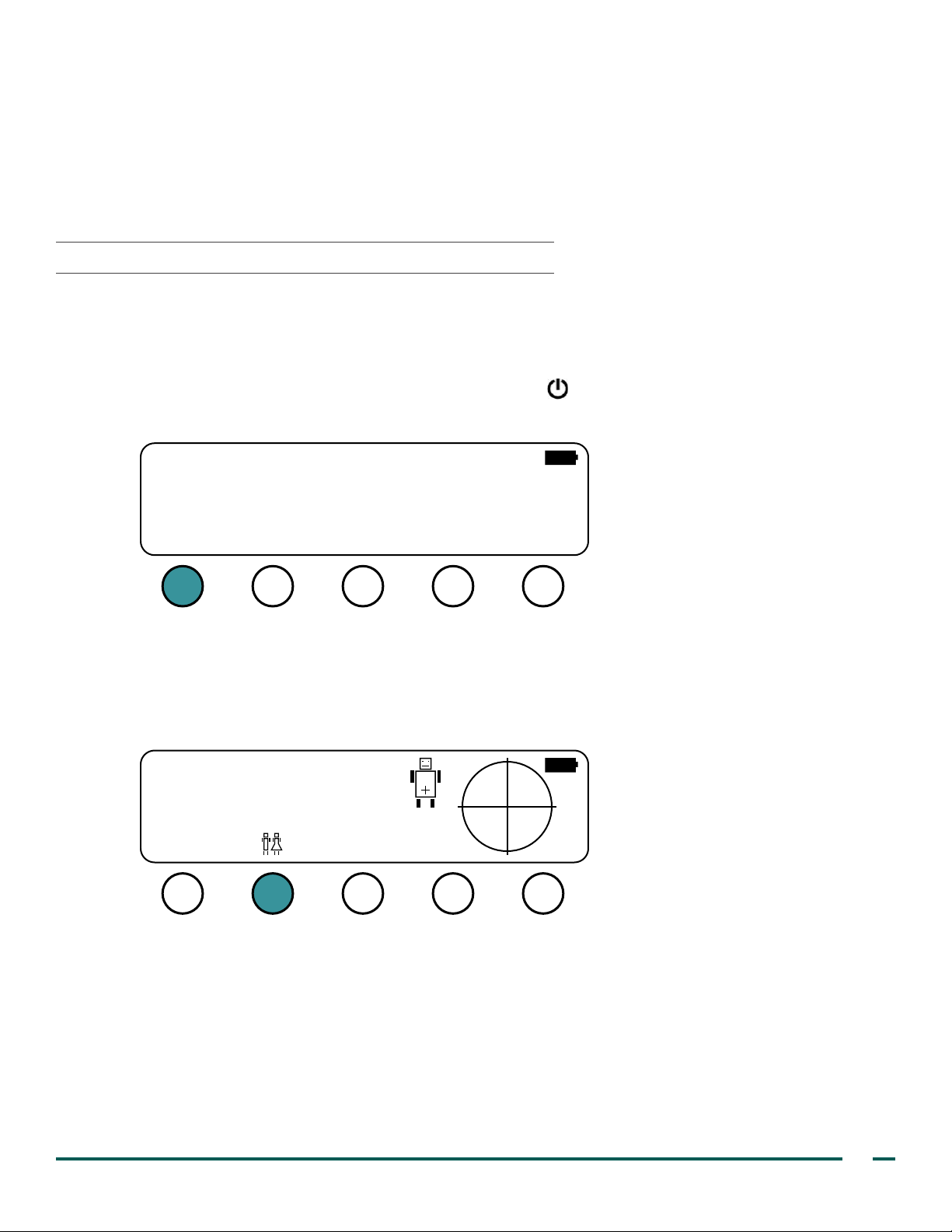
5. On the Scan screen, press the Male/Female button in order to select the patient's gender.
The LCD screen shows a male or a female icon to indicate the gender that is selected. Use the female
option only for women who have not undergone a hysterectomy (the female option allows the instrument
to exclude the uterus from the measurement, which may resemble the bladder ultrasonically). For all other
patients, use the Male option.
READY TO SCAN
DONE SCAN
6. Have the patient lie in the supine position with abdominal muscles relaxed.
7. Palpate the patient’s symphysis pubis (pubic bone).
Operations & Maintenance Manual: Using the Instrument
25
Page 34
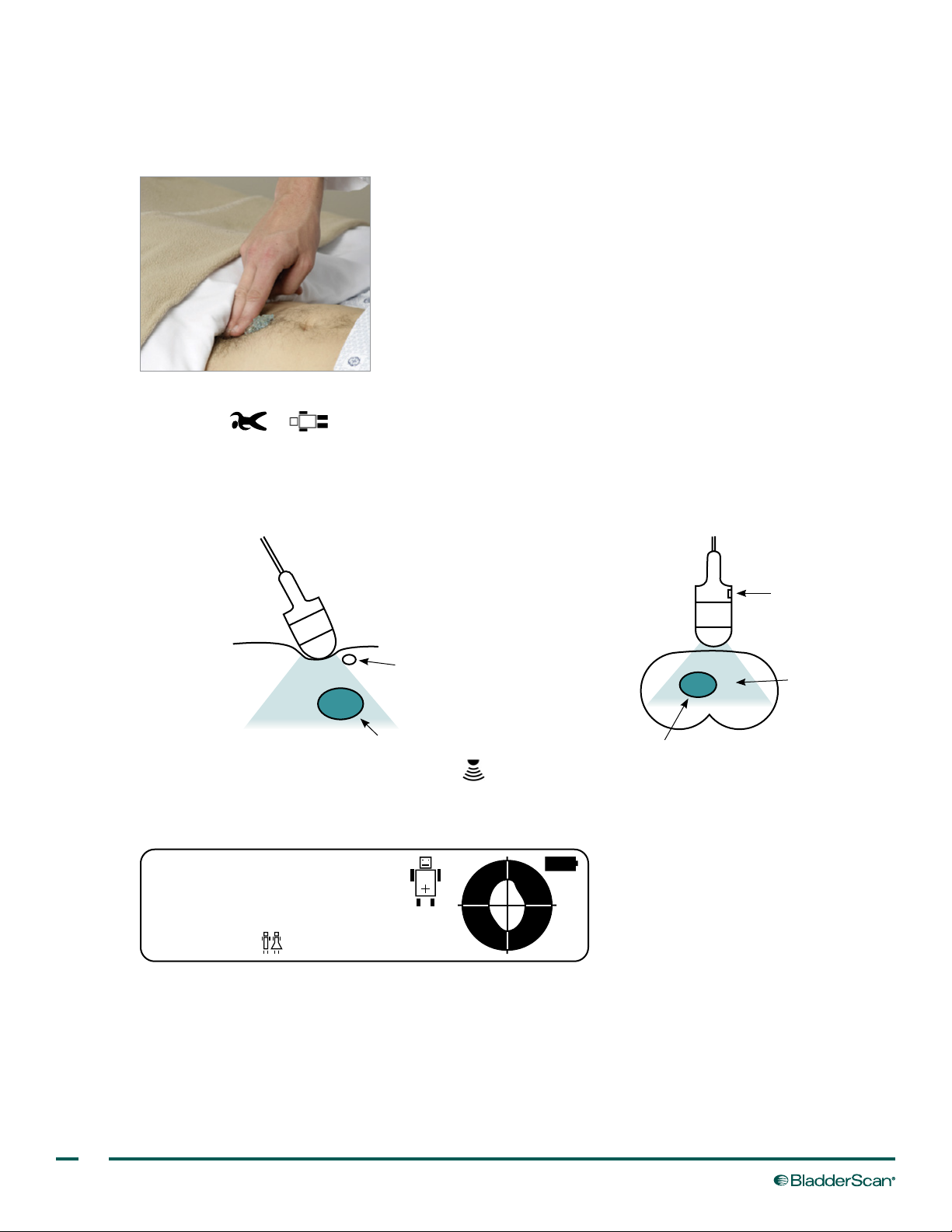
8. Place an ample amount of gel midline on the patient’s abdomen approximately 1 inch (3 cm) above the
132ml
symphysis pubis.
Note: Do not spread the gel over the patient's abdomen, and use a sufciently thick quantity to ensure
proper transmission of ultrasound waves.
9. Place the scanhead on the gel on the patient’s abdomen, ensuring that on the scanhead, the head of the
patient icon ( or ) points toward the head of the patient.
10. Aim the scanhead toward the expected location of the bladder, as illustrated in the following gures. For
most patients, this means aiming the tip of the scanhead toward the patient’s coccyx.
Figure 6. View from Patient's Right Side
Scanhead
(Patient's feet)(Patient's head)
Symphysis pubis
Field of vision
Bladder
Figure 7. View from Patient's Feet
Scanhead
Scan button
(Patient's right side) (Patient's left side)
Field of vision
Bladder
11. On the scanhead, press and release the scan button. The scan initiates.
12. Hold the scanhead steady throughout the scan. The scanhead clicks once at each of the twelve scan
planes. When the scanhead beeps, the scan is complete, and the Aiming screen is displayed.
READY TO SCAN
CURRENT = 132ml
DONE SCAN X
13. If the instrument detects radio frequency interference that could compromise measurement accuracy, the
14. Continue to the following procedure, Verify Aim & Accuracy.
26
screen displays RESCAN. Attempt to locate or disable the source of the outside interference. For more
information, see Electromagnetic Compatibility on page 54.
Page 35
PROCEDURE 2. VERIFY AIM & ACCURACY
132ml
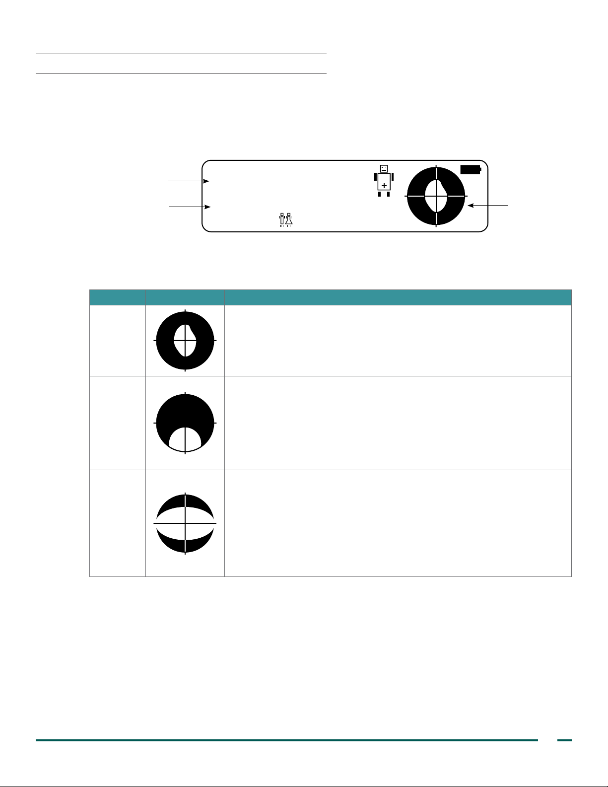
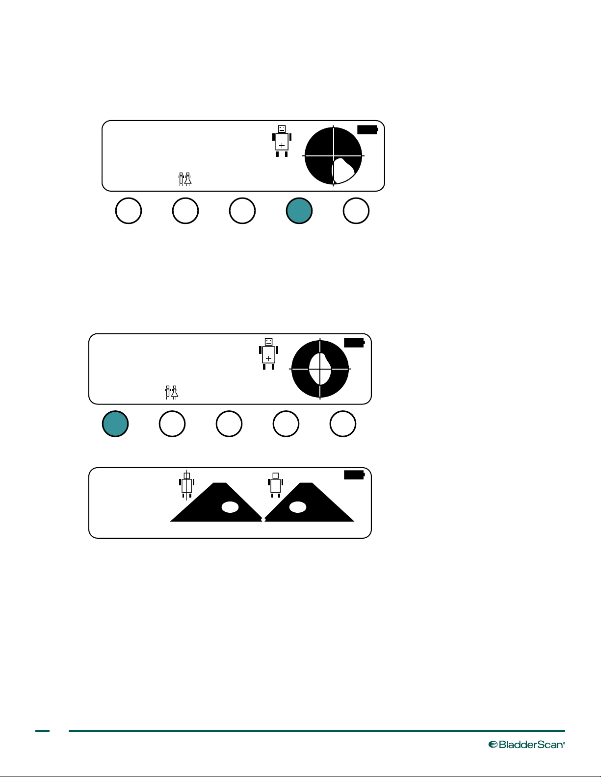
After completing a scan, the BVI 3000 displays two volumes on the Aiming screen: the largest volume measured
and the current volume. The light area inside the target‑shaped Aiming icon represents the position of the
bladder relative to the scanhead.
Figure 8. Aiming Screen
Greatest volume measured
READY TO SCAN
Current volume result
1. Verify that the aim was accurate by comparing the Aiming icon to the results in the following table.
Table 4. Aiming Icons
RESULT AIMING ICON DESCRIPTION
Accurate
CURRENT = 132ml
DONE SCAN X
The bladder image is centered on the crosshairs of the Aiming icon. This
indicates that the scanhead was properly aimed, and the bladder volume
measurement is accurate.
Aiming icon
The bladder image is not centered on the crosshairs and overlaps one
side of the Aiming icon. This indicates that the bladder was outside the
scanhead's eld of vision. In such cases, the measured volume is lower
Off‑center
Volume
too high
2. If the aim is accurate, repeat Step 11 through Step 12 of the Measure Bladder Volume procedure in order to
determine if you are collecting repeatable results. This helps ensure maximum accuracy.
Note: The instrument assumes that the largest volume measured is the true bladder volume, because
in most cases the largest volume is the most accurate. Exceptions occur when the scanhead is moved
during the scan or the incorrect gender was selected. In these situations, the largest volume measurement
may be higher than the actual bladder volume, and you should clear the Aiming screen before rescanning
the patient.
than the true bladder volume. The BVI 3000 recognizes this condition
and displays a greater than (>) symbol before the bladder volume
measurement. To achieve an accurate measurement, re‑aim the scanhead
toward the bladder image, and then repeat the scan.
The bladder overlaps two sides of the Aiming icon. This indicates that
the bladder is too large to be fully contained within the scanhead’s eld
of vision. The instrument recognizes this condition and displays a greater
than (>) symbol before the bladder volume measurement. In such cases,
repositioning or re‑aiming the scanhead will do little to improve accuracy;
however, this situation arises almost exclusively in patients with very large
bladder volumes. At these high volumes, measurements are clinically useful
even if they underestimate the true bladder volume.
Operations & Maintenance Manual: Using the Instrument
27
Page 36
3. If you need to adjust your aim, do the following:
>132ml
132ml
• Press the X button. This clears the inaccurate scan results.
Note: If your instrument does not have an X button, press the DONE button and then press the SCAN
button. This resets the scan.
READY TO SCAN
CURRENT = >132ml
DONE SCAN X
• Move or angle the scanhead toward the direction of the bladder image on the Aiming icon. For example,
if the bladder image is located on the right side of the icon, aim the scanhead so the ultrasound will be
projected further to the right.
• Repeat Step 11 through Step 12 of the Measure Bladder Volume procedure. Verify the accuracy of the
scan according to the instructions in this procedure.
4. When you have collected sufcient scans in order to conrm aiming accuracy, press the DONE button.
READY TO SCAN
CURRENT = 132ml
DONE SCAN X
The Results screen is displayed. Continue to the next procedure, Conrm the Scan Results.
21 cm
2
21 cm
2
132
ml
PRINT NOTESSCAN
MAIN #
28
Page 37
PROCEDURE 3. CONFIRM THE SCAN RESULTS
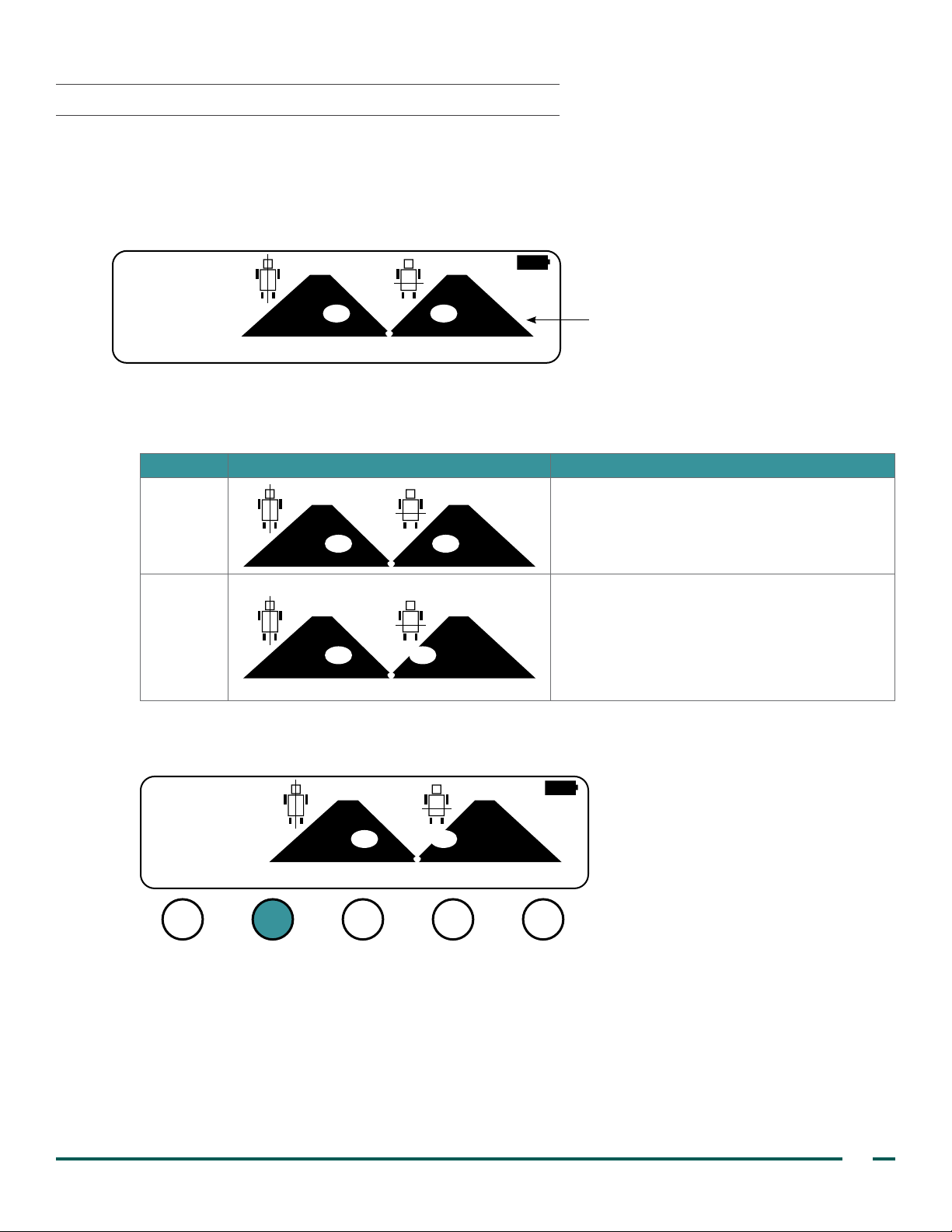
The Results screen displays the longitudinal and horizontal scan planes from the largest image taken during the
exam. The light areas represent the bladder. The dark, triangular surfaces, called scan planes, represent the
scanhead’s eld of vision.
Figure 9. Results Screen
21 cm
2
21 cm
2
132
ml
PRINT NOTESSCAN
1. Conrm that the aim was accurate by comparing the scan plane results to the results in the following table.
Table 5. Scan Plane Result
RESULT SCAN PLANE DESCRIPTION
Accurate
Inaccurate
MAIN #
Scan planes
The light‑colored bladder images are
completely contained within the dark, triangular
scan planes.
The light surface in either scan plane is
overlapping the edge of the black area or
appears to be cut off. Part of the bladder was
not contained in the scanhead’s eld of vision,
and the measurement may underestimate the
patient’s bladder volume.
2. If the scan plane result is inaccurate, press the SCAN button in order to clear the scan result, and then
repeat the procedure Measure Bladder Volume on page 25.
2
21 cm
132
ml
PRINT NOTESSCAN
Operations & Maintenance Manual: Using the Instrument
MAIN #
21 cm
2
29
Page 38
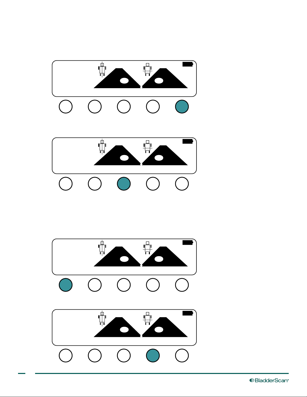
3. If the scan plane result is accurate, do one or more of the following in order to complete the scan and save
the results:
• If you want to add a patient ID number, press the # button, and then complete the procedure Add a
Patient ID Number (Optional) on page 31.
21 cm
2
21 cm
2
132
ml
PRINT NOTESSCAN
• If you want to add notes to the scan results, press the NOTES button, and then complete the procedure
Add Notes (Optional) on page 32.
2
21 cm
MAIN #
2
21 cm
132
ml
PRINT NOTESSCAN
• If you want to print the scan results, press the PRINT button, and then complete the procedure Print the
Scan Result (Optional) on page 34.
MAIN #
Note: If you have enabled the QUICK setting in user preferences, when you press the PRINT button, the
instrument automatically prints the scan results without displaying the Print screen. For more information,
see the procedure Adjust User Preferences on page 21.
21 cm
2
21 cm
2
132
ml
PRINT NOTESSCAN
• If you want to save the results and exit to the Main Menu screen, press the MAIN button.
2
21 cm
MAIN #
2
21 cm
132
ml
PRINT NOTESSCAN
MAIN #
30
Page 39
MANAGING SCAN RESULTS
-D
-D
-D
PROCEDURE 1. ADD A PATIENT ID NUMBER (OPTIONAL)
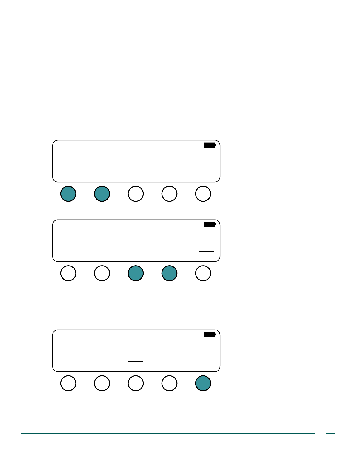
A patient ID number (maximum 10 digits) can be added to the scan result and will be included on the printout.
You may access the Patient ID Number screen from the Scan Results screen. The Patient ID Number screen
displays 0000000000.
Note: Only press the button marked # when a patient ID number is required. If the # button is used and no
patient ID number is entered, the instrument assumes a patient ID number was entered, and 0000000000 will
be included on the printout.
1. Using the left and right buttons, select the digit you want to change (the selected digit is underlined).
00000000000
+
ONE
2. Using the plus + or minus – buttons, increase or decrease the value in order to select the correct digit.
00000000001
3. Repeat Step 1 through Step 2 until you have entered the complete patient ID number.
4. When you have nished entering the patient ID number, press the DONE button.
The instrument returns to the Scan Result screen, and the patient ID number you entered will now be
included on the printout of the scan.
+
ONE
00000875421
+
ONE
Operations & Maintenance Manual: Using the Instrument
31
Page 40
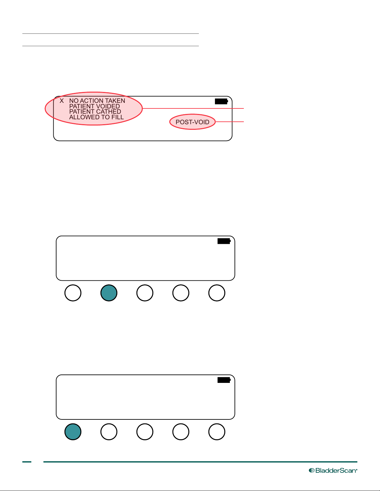
PROCEDURE 2. ADD NOTES (OPTIONAL)
After a scanning procedure has been completed, it is possible to annotate the measurement results, and these
annotations will be included on the printout. You may access the Notes screen from the Scan Results screen.
Figure 10. Notes Screen
NO ACTION TAKENX
PATIENT VOIDED
PATIENT CATHED
ALLOWED TO FILL
EXAM
SEL DONE
TYPE
1. If you would like to change the exam type, press the EXAM TYPE button to toggle between options
as follows:
• POST‑VOID —The measurement was taken after patient voiding. This exam type is selected by default if
the measured bladder volume is less than 100 ml.
• PRE‑VOID—The measurement was taken prior to patient voiding. This exam type is selected by default
if the measured bladder volume is between 100 ml and 400 ml.
• CAPACITY—The measurement was taken prior to patient voiding, and the bladder was lled to
maximum capacity. This exam type is selected by default if the measured bladder volume is greater than
400 ml.
POST-VOID
Action taken
Exam type
NO ACTION TAKENX
PATIENT VOIDED
PATIENT CATHED
ALLOWED TO FILL
EXAM
SEL DONE
TYPE
POST-VOID
2. If you want to note the action taken as a result of the current bladder volume measurement, press the SEL
button in order to select one of the following options:
• NO ACTION TAKEN—This option is selected by default.
• PATIENT VOIDED—The patient was able to void.
• PATIENT CATHED—The patient’s bladder was emptied using a urinary catheter.
• ALLOWED TO FILL—The patient’s bladder was not as full as desired, and voiding was postponed.
NO ACTION TAKENX
PATIENT VOIDED
PATIENT CATHED
ALLOWED TO FILL
EXAM
SEL DONE
TYPE
POST-VOID
32
Page 41
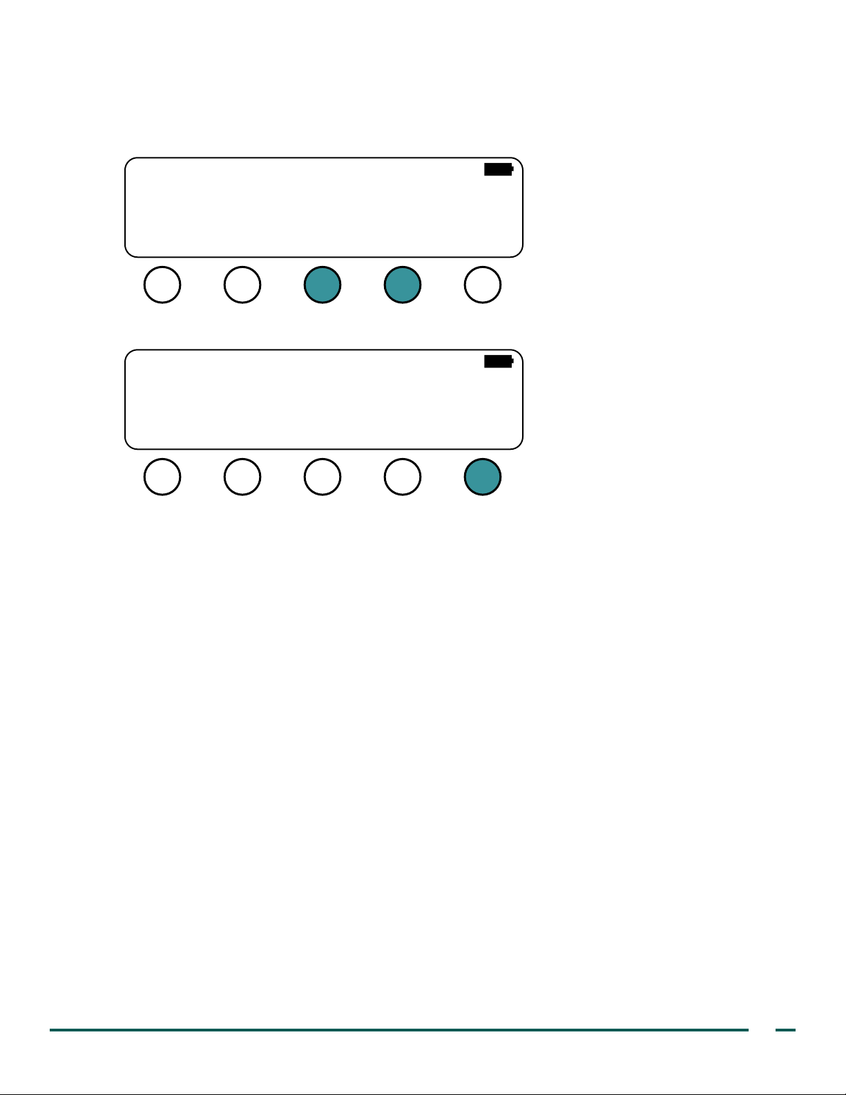
3. If you selected PATIENT VOIDED or PATIENT CATHED in Step 2, enter the amount of urine (rounded to the
nearest 10 ml) that was voided or catheterized by pressing the plus + and minus – buttons.
Note: By default, the amount of voided or catheterized urine is equal to the volume measured during
the scan.
NO ACTION TAKEN
PATIENT VOIDED
X
PATIENT CATHED
ALLOWED TO FILL
EXAM
SEL DONE
4. When you are nished entering notes, press the DONE button.
NO ACTION TAKENX
PATIENT VOIDED
PATIENT CATHED
ALLOWED TO FILL
SEL DONE
TYPE +−
EXAM
TYPE
410 ml
CAPACITY
POST-VOID
Operations & Maintenance Manual: Using the Instrument
33
Page 42
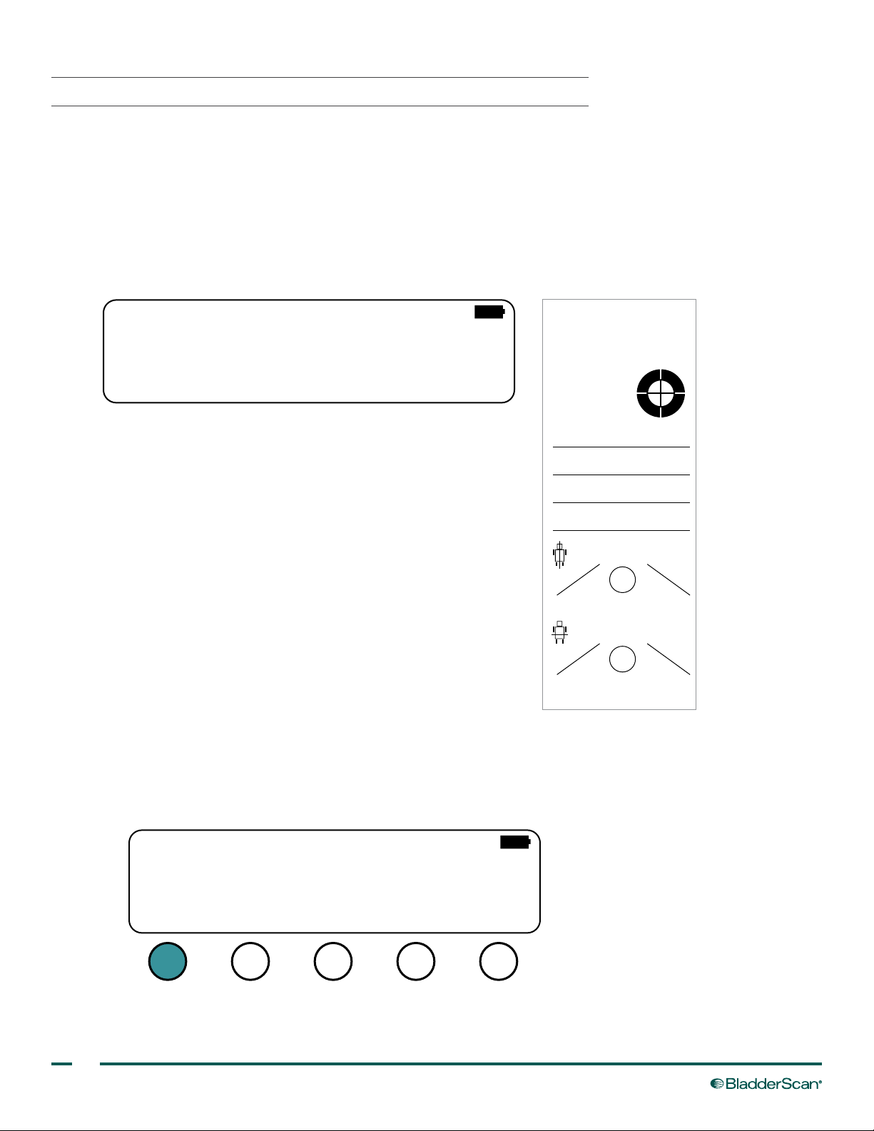
PROCEDURE 3. PRINT THE SCAN RESULT (OPTIONAL)
You may access the Print screen from either the Main Menu screen or the Scan Results screen. For information
about adjusting the scan information that appears on the printout, see the procedure Adjust User Preferences on
page 21.
Note: If you have enabled the QUICK setting in user preferences, you cannot access the Print screen from the
Scan Results screen. If you are on the Scan Results screen and you press the PRINT button, the instrument
automatically prints the scan results without displaying the Print screen.
Figure 11. Print Screen
LAST IMAGEX
COST SAVING
TEST PRINT
PRINT SEL DONE
Note: If the facility name, date, and time
have not been set, those lines will
not be included on the printout.
Figure 12. Printout of Scan Results
BladderScan (tm)
VERATHON
05/27/14 08:55
132 ml
MALE
Patient name:
Patient ID:
Procedure code:
Signature:
Longitudinal axis
Area = 21 cm
Horizontal axis
Area = 21 cm
Probe: 21308 Box: 00001965
VER: 3.020 D949
2
2
1. On the Print screen, ensure that LAST IMAGE is selected. If necessary, press the SEL button in order to
select LAST IMAGE.
2. Press the PRINT button.
Note: Printing takes approximately one minute.
LAST IMAGEX
COST SAVING
TEST PRINT
PRINT SEL DONE
34
Page 43

3. If you would like to cancel printing while it is in progress, press the ABORT PRINT button.
PRINTING IN PROGRESS
ABORT
PRINT
4. When printing is completed, tear the paper from the instrument by pulling the printout towards the back of
the instrument.
5. If desired, create a photocopy of the printout. The BVI 3000 instrument prints on thermal paper. Over time,
the printout will fade. For maximum storage life, Verathon® recommends that you create a photocopy of the
printout.
Operations & Maintenance Manual: Using the Instrument
35
Page 44
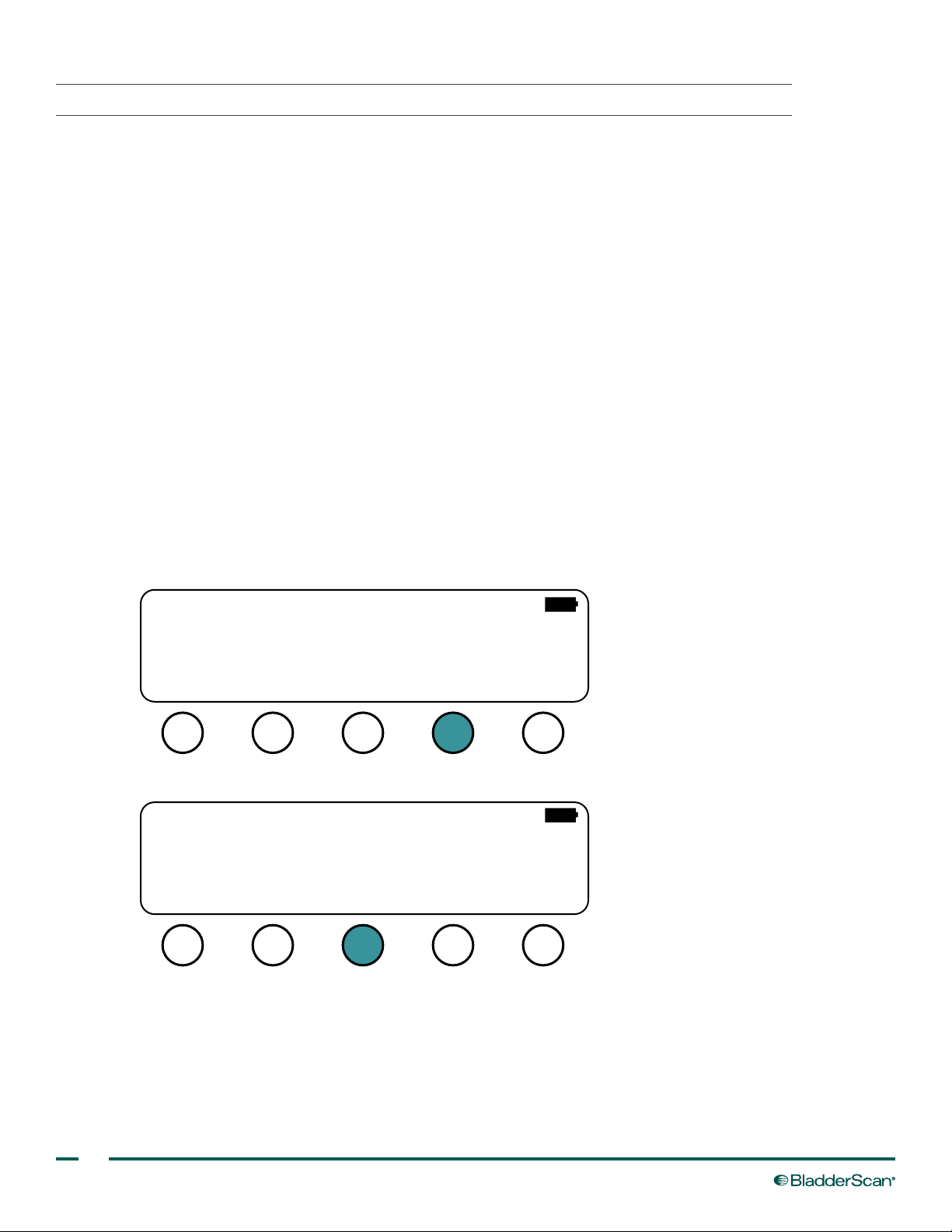
PROCEDURE 4. PRINT A HISTOGRAM OF COST SAVINGS (OPTIONAL)
Each volume measurement from a completed scanning procedure is stored in the instrument’s memory.
Measurement data is stored in one of eleven volume ranges (each with a 100‑ml increment). This data is
analyzed and can be printed at any time.
Cost savings are calculated based on the following criteria:
• Catheterizations avoided—Urinary catheterization below a certain volume is deemed unnecessary.
Thus, by using the BVI 3000, these catheterizations are avoided. The default setting (for volume below
which catheterization is unnecessary) is 300 ml.
• Cost of catheter kits—The default setting is $3 per kit.
• UTIs avoided—Studies indicate that a certain percentage of catheterizations lead to urinary tract
infections (UTIs). By avoiding unnecessary catheterizations, the resulting UTIs may be prevented. The
default setting (for percent of catheterizations leading to UTIs) is 3%.
• Cost of UTIs avoided—Literature suggests that the additional costs associated with treating UTI amount
to $680.00 per patient infection. The default setting is $680.
Total cost savings as a result of using the BVI 3000 = (Caths Avoided x Catheter Costs) + (UTIs Avoided x UTI
Costs).
For information about adjusting the default values used when calculating the cost savings, see the procedure
Adjust User Preferences on page 21.
1. On the Main Menu, press the PRINT button.
BVI 3000
VERATHON
13:2705/22/14
SCAN ALT
2. On the Print screen, press the SEL button until Cost Saving is selected.
LAST IMAGE
COST SAVING
X
TEST PRINT
PRINT SEL DONE
PRINT NOTES
36
Page 45

3. Press the PRINT button. The instrument begins to print the histogram of cost savings. While the instrument
is printing, the cost savings are displayed on the instrument LCD.
Note: Printing takes approximately one minute.
000-199: 2089
200-399: 1077
400-599: 428
600-799: 241
800-999: 74
>1000: 4
CATHs AVOIDED
2089
UTIs AVOIDED
63
SAVINGS
$49107.00
3913
4. When printing is completed, tear the paper from the instrument by pulling the printout towards the back of
the instrument.
Histogram
VERATHON
05/27/14 08:55
Volume
000-099
100-199
200-299
300-399
400-499
500-599
600-699
700-799
800-899
900-999
>1000
CATHs AVOIDED
2089
UTIs AVOIDED
63
SAVINGS
$49,107
scans
870
1,219
589
488
252
176
154
87
69
5
4
5. If desired, create a photocopy of the printout. The BVI 3000 instrument prints on thermal paper. Over time,
the printout will fade. For maximum storage life, Verathon® recommends that you create a photocopy of the
printout.
Operations & Maintenance Manual: Using the Instrument
37
Page 46
CLEANING & DISINFECTING
Routine cleaning and maintenance will help ensure safe and effective operation of the BladderScan BVI 3000
system. Clean and disinfect the instrument before use and between patient exams. For more information,
please contact your authorized BladderScan Service Center, your local BladderScan distributor, or Verathon®
Customer Care.
WARNING
This product may only be cleaned and disinfected by using the approved processes provided in
this manual. Cleaning and disinfection methods listed are recommended by Verathon
compatibility with component materials.
WARNING
Availability of cleaning and disinfection products varies by country, and Verathon is unable
to test products in every market. For more information, please contact Verathon Customer
Care at 1.800.331.2313 or your local representative. For additional contact information, visit
verathon.com/contact‑us.
WARNING
Ensure that you follow the manufacturer’s instructions for handling and disposing of the cleaning
and disinfection solutions provided in this manual.
PROCEDURE 1. CLEAN THE INSTRUMENT
WARNING
®
based on
Cleaning is critical to ensuring the component is ready for disinfection. Failure to properly clean the
device could result in a contaminated instrument after completing the disinfection procedure.
Cleaning is the removal of all visible soil or contaminants from the exterior surfaces of the device. The device
must be cleaned after every use, and cleaning is an essential step before disinfection.
1. Wipe the acoustic coupling gel completely off the scanhead.
2. Use a moistened, soft cloth to remove particulate matter or body uids that remain on the instrument.
3. Do not re‑use cloths or wipes.
4. Allow the device to air dry, or towel dry with a clean dry cloth. Next, you must disinfect the instrument.
38
Page 47

PROCEDURE 2. DISINFECT THE INSTRUMENT
IMPORTANT
Failure to heed the following may cause device damage not covered by the warranty:
• Do not immerse the instrument in the disinfectant solution.
• Do not subject any part of the instrument to steam, ethylene oxide, radiation, or similar methods of
sterilization or autoclaving.
®
• Do not use CidexPlus
Disinfectants and cleaning methods listed are based on compatibility with product materials, not biological
effectiveness. Refer to the instructions from the manufacturer of the disinfectant for guidance on biological
effectiveness of the disinfectant.
The following liquid disinfectants and wipes are compatible with the materials used in the instrument:
to disinfect the instrument. CidexPlus will damage the plastic enclosure.
• A‑456® II Disinfectant
®
• Accel
• CaviCide
• CaviWipes
• Chloro‑Sol Spray
TB Wipes
®
®
®
• Clorox® Germicidal Wipes
• Mikro Quat
• Sani‑Cloth
• Sani‑Cloth
• Sani‑Cloth
• Sporicidin
• T‑Spray II
®
Bleach Wipes
®
Germicidal Wipes
®
Plus Germicidal Wipes
®
Disinfecting Towelettes
®
The level of disinfection required for a device is based on the type of tissue it contacts during use. Based on the
intended use of the BladderScan BVI 3000 system, low‑level disinfection is the minimum level required.
1. Ensure the instrument has been properly cleaned according to the procedure Clean the Instrument on
page 38.
2. Ensure the disinfectant has not expired.
3. If using a liquid disinfectant, prepare the disinfection solution according to the manufacturer’s label
instructions, ensuring that you are using the proper concentration.
4. Apply the solution to a soft cloth or wipe.
Note: Do not spray or apply liquid disinfectants directly to the surface of the device, and do not soak the
device in liquids.
5. Wipe the surfaces of the device and allow the surface to remain wet for the required contact duration. Follow
the manufacturer’s instructions for the appropriate disinfection level contact duration.
6. Do not re‑use cloths or wipes.
7. If rinsing or removal of the disinfectant solution from the device is required by the disinfectant manufacturer’s
instructions, wipe with a clean soft cloth dampened in sterile water. Verathon® recommends wiping the
device three separate times to remove all residual disinfectant.
8. Allow the device to air dry, or towel dry the device with a clean, dry cloth.
Operations & Maintenance Manual: Cleaning & Disinfecting
39
Page 48

MAINTENANCE & TROUBLESHOOTING
ANNUAL CERTIFICATION OF CALIBRATION
Verathon® recommends that the BVI 3000 be certied by an authorized Verathon Service Center once a year.
Certication service includes a comprehensive inspection and testing of the instrument in order to ensure
accurate measurement performance. For more information, please contact the Verathon Service Center or your
local distributor.
If the calibration due date for your BVI 3000 has passed, the message “Calibration Due” will appear every
time you turn on the instrument. You can still measure bladder volume; however, this message will continue to
appear until an authorized Verathon Service Center calibrates the instrument.
PERIODIC INSPECTIONS
WEEKLY INSPECTIONS
Once a week, you should inspect the control unit, scanhead, cable, power supply, power cords, batteries, and
plugs for damage or cracks. Cracks that allow the ingress of uid into the control unit or scanhead may affect the
performance of the instrument. Any apparent cracks or faults in the control unit, scanhead, or the cable that links the
control unit and the scanhead must be referred to your authorized Verathon Service Center or your local distributor.
MONTHLY ACCURACY CHECK
Each month, or whenever accuracy assessment is desired, you should test the accuracy of the instrument
according to the instructions in the procedure Verify Instrument Accuracy on page 47.
DEVICE REPAIR
The BladderScan BVI 3000 system components are completely sealed and not user‑serviceable. Verathon®
does not make available any type of circuit diagrams, component parts lists, descriptions, or other information
that would be required for repairing the device and related accessories. All service must be performed by a
qualied technician.
If you have any questions, contact your local Verathon representative or Verathon Customer Care.
WARNING
Electric shock hazard. Do not attempt to open the system components. This may cause serious
injury to the operator or damage to the instrument and will void the warranty. Contact Verathon
Customer Care for all servicing needs.
WARNING
40
No modication of this equipment is allowed.
Page 49
TROUBLESHOOTING
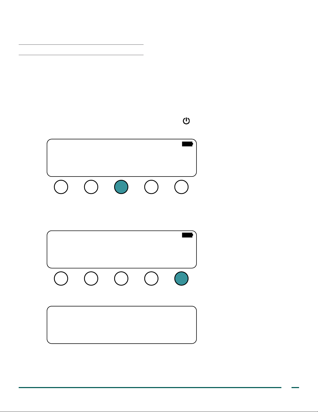
BVI 3000
PROCEDURE 1. RUN A SELF TEST
The following tests are completed as part of the self test:
• ROM Test—Program memory
• BUS Test —Microprocessor bus
• NVRAM Test —Non‑volatile, battery‑backed memory
• SRAM Test—Main memory
• FLASH Test—Flash memory
1. Turn the BladderScan BVI 3000 on by pressing the power button.
2. On the Main Menu screen, press the A LT button.
VERATHON
SCAN ALT
13:2705/22/14
PRINT NOTES
3. If you are prompted, enter your PIN code.
Note: The default PIN code is 0000.
4. On the Alternate Menu screen, press the SELF TEST button. The instrument begins the self test.
VER: 3.020 (D949)
Box ID: 00001965
Copyright 2013 by
VERATHON Corporation
NAME TIMEDATE
As the test is completed, the Self Test screen displays the status of the systems tested. When the test is
complete, the instrument returns to the Main Menu screen.
ROM Te st PASSED
Bus Te st PASSED
NVRAM Te st PASSED
SRAM Te st PASSED
FLASH Te st PASSED
5. If any of the self‑test systems does not pass, contact Verathon Customer Care or your local representative.
PREF
SELF
TEST
Operations & Maintenance Manual: Maintenance & Troubleshooting
41
Page 50
PROCEDURE 2. TROUBLESHOOT POWER ISSUES
If the instrument does not turn on, this is usually due to a dead or discharged battery and can be xed simply by
replacing the dead battery with a charged one.
1. Check the battery icon in the upper‑right corner of the LCD screen.
2. If the battery icon is clear (empty), replace the battery or recharge the current battery. For more information,
see Charge the Batteries on page 10.
3. If replacing or charging the battery does not resolve the issue, contact Verathon® Customer Care or your
local representative.
PROCEDURE 3. TROUBLESHOOT AN ERROR MESSAGE
BATTERY CHARGE LEVEL
When the battery’s charge is too low to allow normal operation (but not too low to permit operation of the
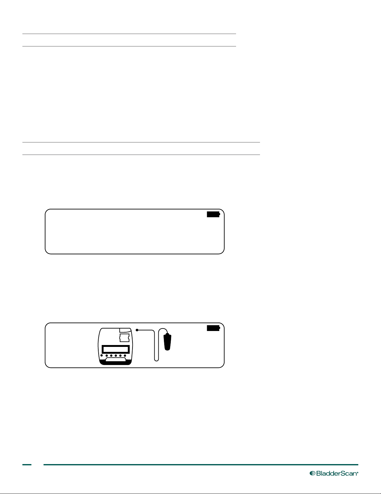
internal circuitry) the BVI 3000 displays the following message: BATTERY CHARGE LEVEL IS TOO LOW FOR
INSTRUMENT OPERATION. RECHARGE BEFORE NEXT USE.
BATTERY CHARGE LEVEL
IS TOO LOW FOR
INSTRUMENT OPERATION.
RECHARGE BEFORE NEXT USE.
1. Replace the battery or recharge the current battery. For more information, see Charge the Batteries on
page 10.
NO SCANHEAD
The following image is displayed if the user presses the SCAN button when the scanhead is not connected to
the control unit.
1. Connect the scanhead to the control unit according to the instruction in the procedure Connect the
Scanhead to the Control Unit on page 13. When the scanhead is properly attached to the control unit, the
error disappears, and the instrument operates normally.
42
Page 51
PRINTHEAD DISENGAGED
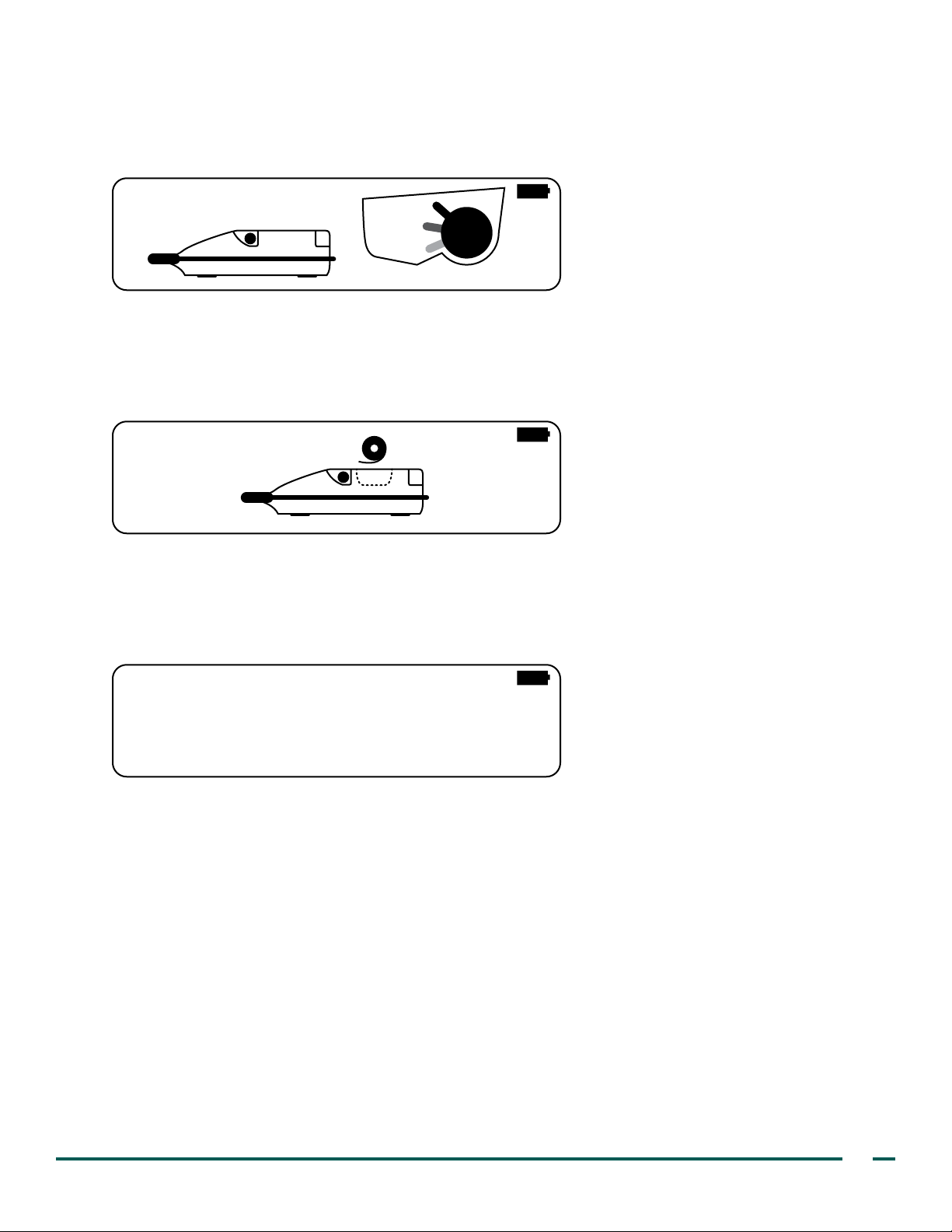
The instrument senses when the printhead is disengaged and displays the following image until the printhead
release lever is positioned up as far as it can go.
1. Turn the printhead release lever so that it is pointing to 10 o'clock.
NO PAPER
The BVI 3000 displays the following image when the printer is out of paper.
1. Load paper according to the instructions in the procedure Load The Thermal Paper Roll on page 14.
TOO HOT
The BVI 3000 displays the following message if the printhead overheats.
TOO HOT
1. Turn off the BVI 3000, and then wait for the instrument to cool down.
2. Ensure that this is not the result of a paper jam. For more information, see Clear a Paper Jam on
page 44.
3. If the printhead continues to overheat, contact Verathon® Customer Care or your local representative.
RESCAN (INTERFERENCE)
The BVI 3000 displays the message RESCAN if it detects interference of sufcient magnitude to possibly
compromise measurement accuracy. For more information, see Electromagnetic Compatibility on page 54.
1. Locate the source of the interference.
2. Disable or remove the interference source, or use the BVI 3000 away from the interference source.
3. If these efforts do not restore normal operation, contact Verathon® Customer Care.
Operations & Maintenance Manual: Maintenance & Troubleshooting
43
Page 52
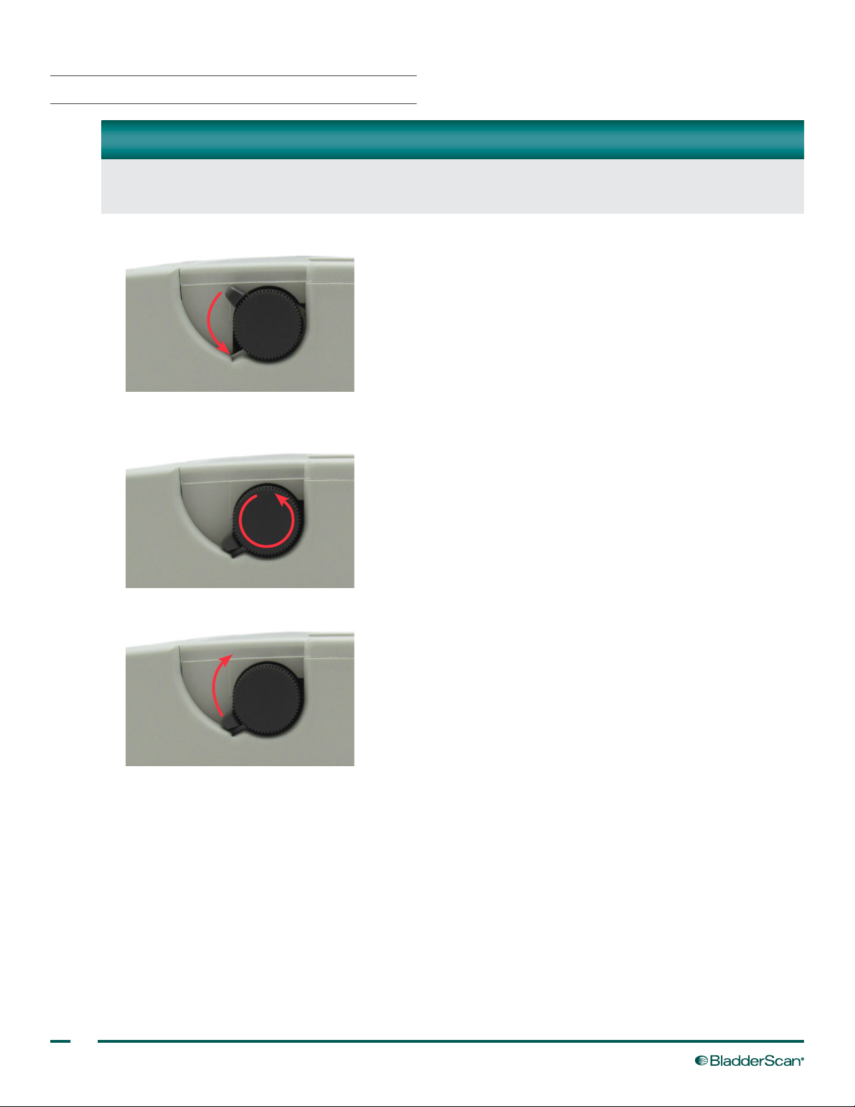
PROCEDURE 4. CLEAR A PAPER JAM
IMPORTANT
If the paper jam is inaccessible, do not try to disassemble the printer. Contact your authorized Verathon®
Service Center or your local Verathon distributor for service.
1. On the right side of the instrument, next to the paper roll well, lower the printhead release lever.
2. While moving the manual paper‑feed wheel counterclockwise, gently pull the paper backward until the paper
jam is cleared and the paper roll is free of the instrument.
3. Turn the printhead release lever so that it is pointing to 10 o'clock.
4. Trim any damaged paper off of the paper roll.
5. Ensure that the new end of the paper roll is cut straight. Do not fold the end of the paper roll, cut it
diagonally, or cut it to a point.
6. Reload the paper roll according to the instructions in the procedure Load The Thermal Paper Roll on
page 14.
44
Page 53
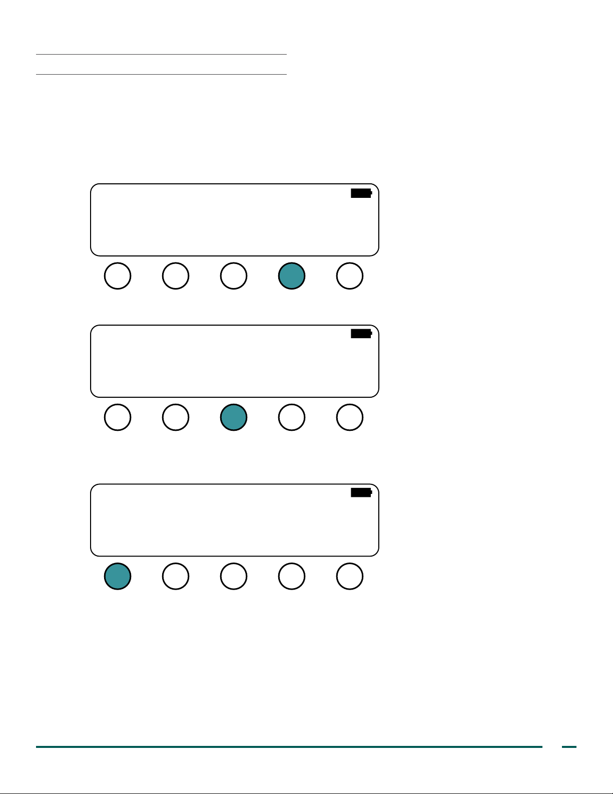
PROCEDURE 5. TEST THE PRINTER
Select this option to test if the built‑in thermal printer works. The instrument will print alphanumeric characters
and a simple grayscale test pattern.
1. Ensure a paper roll has been inserted into the instrument according to the instructions in the procedure Load
The Thermal Paper Roll on page 14.
2. On the Main Menu screen, press the PRINT button.
BVI 3000
VERATHON
SCAN ALT
3. On the Print screen, press the SEL button until TEST PRINT is selected.
LAST IMAGE
COST SAVING
TEST PRINT
X
13:2705/22/14
PRINT NOTES
PRINT SEL DONE
4. Press the PRINT button. The instrument begins printing.
Note: Printing takes approximately one minute.
LAST IMAGE
COST SAVING
TEST PRINT
X
PRINT SEL DONE
Operations & Maintenance Manual: Maintenance & Troubleshooting
45
Page 54
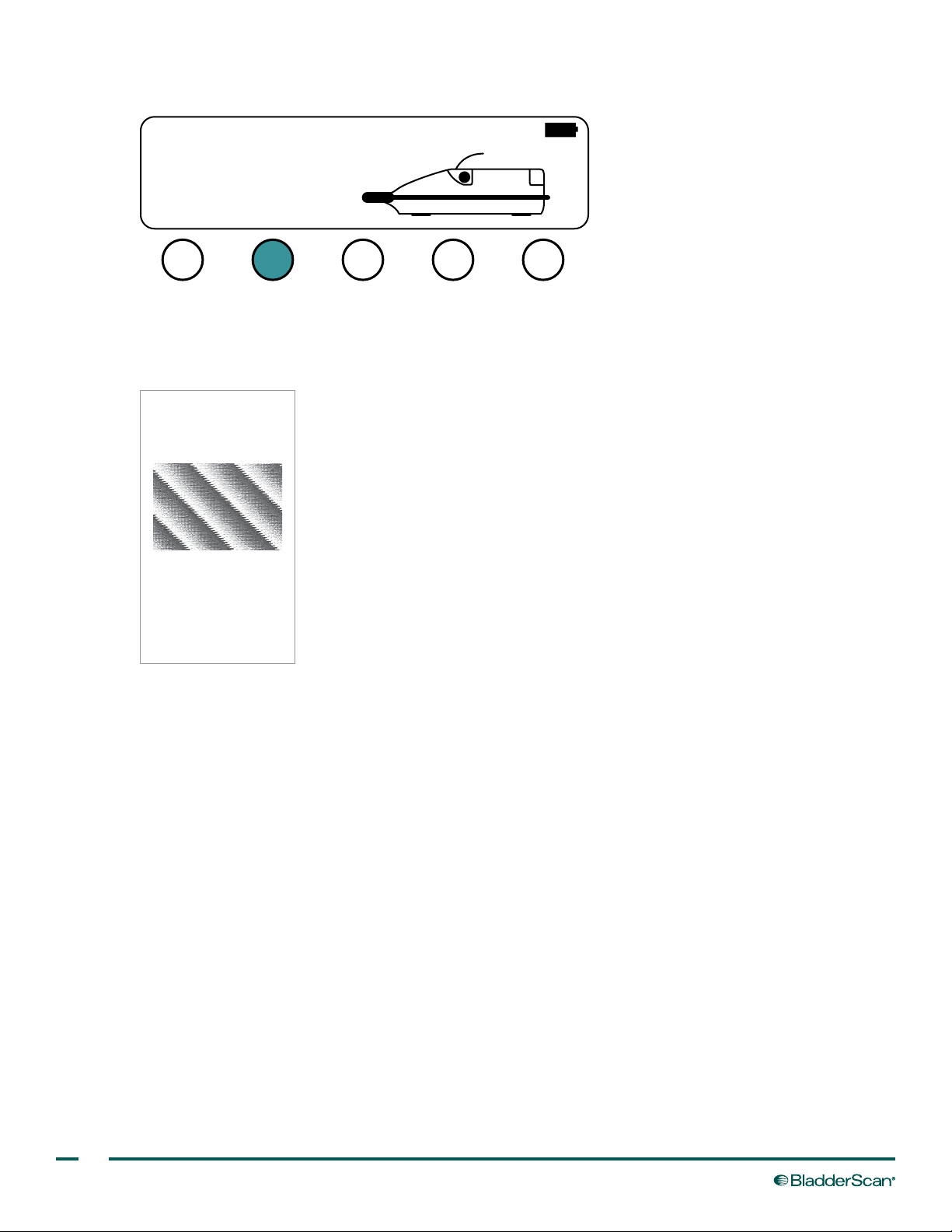
5. If you would like to cancel printing while it is in progress, press the ABORT PRINT button.
PRINTING IN PROGRESS
ABORT
PRINT
6. When printing is completed, tear the paper from the instrument by pulling the printout towards the back of
the instrument.
7. Ensure that the instrument prints an array of alphanumeric characters and a simple grayscale test pattern.
!"#$%&’()*+,-./01234
56789:;<+>?@ABCDEFGHI
JKLMNOPQRSTUVWXYZ[]
_ʽabcdefghijklmnopqrs
tuvwxyz{|}~ьдеДЕЙЖцхп
000
000
002
001
004
002
006
003
008
004
Probe: 21308 Box: 00001965
VER: 3.020 D949
Probe Scan Count: 865
Console Scan Count: 1282
000
000
001
001
002
46
Page 55

PROCEDURE 6. VERIFY INSTRUMENT ACCURACY
Measurement accuracy is dependent upon aiming the scanhead so that the bladder falls entirely within the
measurement cone and following the proper instructions for use. When conrming measurement accuracy,
ensure that you are measuring the bladder volume according to the instructions in this manual.
1. According to the instructions in the chapter Using the Instrument on page 24, measure the pre‑void
volume of a bladder.
2. Void or catheterize into a measurement beaker. This is called the voided volume.
3. According to the instructions in the chapter Using the Instrument on page 24, measure the post‑void
volume of the bladder. This checks for any post‑void residual (PVR).
4. Subtract the post‑void measurement collected in Step 3 from the pre‑void measurement collected in Step 1.
This is called the measured volume.
5. Compare the voided volume collected in Step 2 to the measured volume from Step 4.
If the voided volume is less than 699 ml, the measured volume should be within ± (20% + 20 ml).
If the voided volume is more than 699 ml, the measured volume should be within ± (25% + 25 ml).
6. If the measured volume is not within the accuracy range, contact Verathon Customer Care or your local
representative.
DEVICE DISPOSAL
Disposal of this device in accordance with WEEE requirements can be coordinated through your Verathon®
Service Center.
Operations & Maintenance Manual: Maintenance & Troubleshooting
47
Page 56

WARRANTY
Verathon® warrants the BladderScan BVI 3000 against defects in material and workmanship for one (1) year
from the date of purchase from Verathon Inc. Warranty extensions are available. For more information, contact
Verathon Customer Care or your local representative. For contact information, see verathon.com/contact‑us.
Pursuant to this warranty, a service center authorized by Verathon will repair or replace units that prove to be
defective during the warranty period.
This warranty is given only to the original purchaser of the BladderScan instrument. This warranty does not
cover equipment sold as used.
This warranty does not apply if the product has been damaged by misuse or as the result of service or
modication by anyone other than a service center authorized by Verathon.
The unit must be used in accordance with the instructions contained in this manual. Consumable items are not
covered in this warranty and should be used in conformance with Verathon product specications, as provided
in the Product Specications chapter.
Warranty conditions may differ in some countries. Contact your local distributor for warranty terms.
DISCLAIMER OF ADDITIONAL WARRANTIES
There are no understandings, agreements, representations of warranties expressed or implied (including
warranties of merchantability or tness for a particular purpose) other than those set forth in the preceding
Warranty section. The contents of this manual do not constitute a warranty.
Some states disallow certain limitations on applied warranties. The purchaser should consult state law if there
is a question regarding this disclaimer. The information, descriptions, recommendations, and safety notations
in this manual are based upon Verathon experience and judgment, as of June 2014, with respect to the
BladderScan BVI 3000 instrument. The contents of this manual should not be considered to be all‑inclusive or
covering all contingencies.
Please direct any questions or problems concerning bladder volume measurement, using the instrument, or the
interpretation of data to the responsible physician.
48
Page 57

PRODUCT SPECIFICATIONS
SAFETY & PERFORMANCE SUMMARY
• The BladderScan BVI 3000 computes the volume of the urinary bladder based upon twelve,
cross‑sectional ultrasound images. For maximum accuracy, be sure to hold the scanhead motionless
while scanning.
• The most accurate measurements are obtained when the patient rests quietly in the supine position.
• Accuracy is compromised if the user does not obtain an optimal, repeatable image.
• Errors in usage tend to result in the underestimation of bladder volume, except in cases where the
scanhead is moved during scanning. In this case, the measurement may overestimate the patient’s
bladder volume.
• The BladderScan BVI 3000 is not intended for use on pregnant patients.
• The patient being scanned should not have a catheter in his or her bladder. This could create micro
bubbles in the bladder, which affect the accuracy of the measurement.
• Do not use the BVI 3000 on patients with open skin or wounds in the suprapubic region.
• Use care when scanning suprapubic and pelvic surgery patients. Scar tissue, surgical incisions, sutures,
and staples can affect ultrasound transmission and reection.
• To conserve power, the BladderScan BVI 3000 turns off automatically when not in use.
• Verathon® recommends that new operators rst use the BVI 3000 on patients with moderately full
bladders, rather than initially attempting to locate a bladder with a low volume.
• Warning: There is the possible hazard of explosion if the BVI 3000 is used in the presence of ammable
anesthetics.
ACCURACY RANGE
Given the tremendous variation of healthy and compromised human anatomy, a guaranteed accuracy
specication for the instrument used on humans would be difcult. The accuracy that an individual achieves
when using the BVI 3000 depends on properly aiming the scanhead so that the bladder falls entirely within
the measurement cone. Ensure that you follow the instructions for use in the chapter Using the Instrument on
page 24.
It is suggested that you verify instrument accuracy by scanning a calibrated adult bladder tissue‑equivalent
phantom (if available) or by completing the procedure Verify Instrument Accuracy on page 47.
Table 6. Scanning Accuracy Range
BLADDER VOLUME ACCURACY RANGE
0 to 699 ml ± (20% + 20 ml)
700 to 999 ml ± (25% + 25 ml)
Operations & Maintenance Manual: Product Specications
49
Page 58

COMPONENT SPECIFICATIONS
CONTROL UNIT & SCANHEAD SPECIFICATIONS
Table 7. General Specications
SPECIFICATION VALUE
Classication Electrical Class II, Applied Part BF
Input Rechargeable nickel–metal hydride (NiMH) battery.
Transient overvoltage Category II
Integrated printer Thermal printer
Ingress protection against water
Table 8. Operating & Storage Conditions
SPECIFICATION VALUE
Use Indoor
Ambient temperature range 10–40ºC (50–104ºF)
Atmospheric pressure range 700–1060 hPa
Relative humidity 30–75% non‑condensing
Storage Indoor
Ambient temperature range ‑20–60ºC (‑4–140ºF)
Atmospheric pressure range 500–1060 hPa
Relative humidity 20–95% non‑condensing
IPX1 (drip‑proof, a higher than ordinary level of protection from
drips, leaks, and spills)
Operating Conditions
Storage Conditions
50
Page 59

Table 9. Ultrasound Acoustic Output Parameters
Values in this table are the maximum readings obtained from three test results.
ACOUSTIC OUTPUT MI
Global Maximum Value 0.218* 0.0676 2.95
pr.3 (MPa) 0.317
Wo (mW) 0.0676 0.238
fc (MHz) 2.12 2.12 2.12
zsp (cm) 2.80 2.80
Associated
Acoustic
Parameter
Beam
dimensions
x‑6 (cm) 0.367
y‑6 (cm) 0.377
PD (µsec) 1.17 1.17
PRF (Hz) 400 400
Az. (cm) 5.46
EDS
Ele. (cm) 1.20
TIS/TIB/TIC range 0.0‑1.0*
Image Rate 5.55 Hz
M‑Lines 72
Sector Angle 120°
Sector Offset 2.035 cm
I
SPTA.3
(mW/cm2)
I
SPPA.3
(W/cm2)
* Both MI and TI values are below 1.0.
Operations & Maintenance Manual: Product Specications
51
Page 60

BATTERY CHARGER SPECIFICATIONS
Use only the battery charger supplied. Use of any other charger may damage the battery pack.
The power supply for the battery charger used with the BVI 3000 is tested to IEC 60601‑1 requirements and is
in compliance with UL and CSA equivalent standards.
The power supply is not intended for direct patient contact. The batteries used in the BVI 3000 are charged
separate from the control unit and not during patient use.
Table 10. Battery Charger Specications
SPECIFICATION VALUE
Electrical Specications
100‑120 VAC/North American (LZA‑) units
Input voltage
Input frequency 50–60 Hz
Input current
Output No load to full load at rated voltage. Refer to unit label
200‑250 VAC/European (LZE‑) units
100‑250 VAC/Universal (LZU‑) units
0.39 A/North American (LZA‑) units
0.25 A/European (LZE‑) units
0.38 A/Universal (LZU‑) units
Input connection The power supply employs a direct plug in AC prongs for wall plug‑in units
Insulation The power supply is Class I with basic insulation to each terminal
Environmental Specications
Operating temperature 10 to 40°C (50 to 104°F)
Transient overvoltage Category II
Pollution degree II
Atmospheric pressure 700 hPa to 1060 hPa
Relative humidity 30 to 75%, non‑condensing
Ventilation The power supply is designed to operate with free air convection.
The earth terminal provided in this unit is a functional earth terminal, as
Earth terminal
Fuses The fuses used in the power supply are rated at 250 VAC, 2 A, quick acting.
indicated by the ground symbol on the unit. It is not utilized in the power supply
to provide earth protection. Various ground options are available upon request.
52
Page 61

BATTERY SPECIFICATIONS
SPECIFICATION VALUE
Battery type Rechargeable nickel–metal hydride (NiMH)
Nominal voltage 7.2 V
Battery service life >500 cycles (IEC standard), approximately 2 years at 5 cycles per week
Charging time and conditions 160 mA for 16 hours at 20°C (68°F)
Rated capacity 1.6 Ah
Charging voltage 9–32 V DC source
Max weight 195 g (0.43 lbs)
Width 61 mm (2.4 in)
Length 59 mm (2.3 in)
Height 36 mm (1.4 in)
Operations & Maintenance Manual: Product Specications
53
Page 62

ELECTROMAGNETIC COMPATIBILITY
BladderScan BVI 3000 system is designed to be in compliance with IEC 60601‑1‑2:2007, which contains
electromagnetic compatibility (EMC) requirements for medical electrical equipment. The limits for emissions and
immunity specied in this standard are designed to provide reasonable protection against harmful interference in
a typical medical installation.
In addition, the BVI 3000 detects outside interference and displays RESCAN instead of a volume
measurement if the detected interference is of sufcient magnitude to possibly compromise measurement
accuracy. If you experience this display repeatedly, see the entry "Rescan (Interference)" in the procedure
Troubleshoot an Error Message on page 42.
The BladderScan BVI 3000 system complies with the applicable essential performance requirements specied
in IEC 60601‑1 and 60601‑2‑37. Results of immunity testing show that the essential performance of the system
is not affected under the test conditions described in the following tables. For more information about the
essential performance of the BladderScan BVI 3000 system, see Essential Performance on page 1.
ELECTROMAGNETIC EMISSIONS
Table 11. Guidance and Manufacturer’s Declaration—Electromagnetic Emissions
The BladderScan BVI 3000 system is intended for use in the electromagnetic environment specied below. The
customer or the user of the BladderScan BVI 3000 system should assure that it is used in such an environment.
EMISSIONS TEST COMPLIANCE ELECTROMAGNETIC ENVIRONMENT – GUIDANCE
RF emissions
CISPR 11
RF emissions
CISPR 11
Harmonic emissions
IEC 61000‑3‑2
Voltage uctuations/
icker emissions
IEC 61000‑3‑3
Group 1
Class A
Class A
Complies
The BladderScan BVI 3000 system uses RF energy only for its
internal function. Therefore, its RF emissions are very low and are
not likely to cause any interference in nearby electronic equipment.
The BladderScan BVI 3000 system is suitable for use in all
establishments other than domestic and those directly connected to
the public low‑voltage power supply network that supplies buildings
used for domestic purposes.
54
Page 63

ELECTROMAGNETIC IMMUNITY
Table 12. Guidance and Manufacturer’s Declaration —Electromagnetic Immunity
The BladderScan BVI 3000 system is intended for use in the electromagnetic environment specied below. The
customer or the user of the BladderScan BVI 3000 system should assure that it is used in such an environment.
IMMUNITY TESTS IEC 60601 TEST LEVEL
Electrostatic discharge
(ESD)
IEC 61000‑4‑2
Electrical fast transient/
burst
IEC 61000‑4‑4
Surge
IEC 61000‑4‑5
± 6 kV contact
± 8 kV air
± 2 kV for power supply lines
± 1 kV for input/output lines
± 1 kV line(s) to line(s)
± 2 kV line(s) to earth
<5% Ut (>95% dip in Ut)
for 0.5 cycle
Voltage dips, short
interruptions and
voltage variations on
power supply input lines
IEC 61000‑4‑11
40% Ut (60% dip in Ut)
for 5 cycles
70% Ut (30% dip in Ut)
for 25 cycles
<5% Ut (>95% dip in Ut)
for 5 s
Power frequency
(50/60 Hz) magnetic
eld
3 A/m In compliance
IEC 61000‑4‑8
Conducted RF
IEC 61000‑4‑6
3 Vrms
150 kHz to 80 MHz
COMPLIANCE
LEVEL
In compliance
In compliance
In compliance
In compliance
3 V
ELECTROMAGNETIC ENVIRONMENT
– GUIDANCE
Floors should be wood, concrete,
or ceramic tile. If oors are covered
with synthetic material, the relative
humidity should be at least 30%.
Mains power quality should be that
of a typical commercial or hospital
environment.
Mains power quality should be that
of a typical commercial or hospital
environment.
Mains power quality should be that
of a typical commercial or hospital
environment. If the user of the
BladderScan BVI 3000 system
requires continued operation
during power mains interruptions,
it is recommended that the
BladderScan BVI 3000 system be
powered from an uninterruptible
power supply or a battery.
Power frequency magnetic
elds should be at levels
characteristic of a typical location
in a typical commercial or hospital
environment.
Portable and mobile RF
communications equipment should
be used no closer to any part of
the BladderScan BVI 3000 system,
including cables, than the
recommended separation distance
calculated from the equation
applicable to the frequency of the
transmitter.
Operations & Maintenance Manual: Product Specications
Recommended separation
distance d (m)
d=1.2 √P
55
Page 64
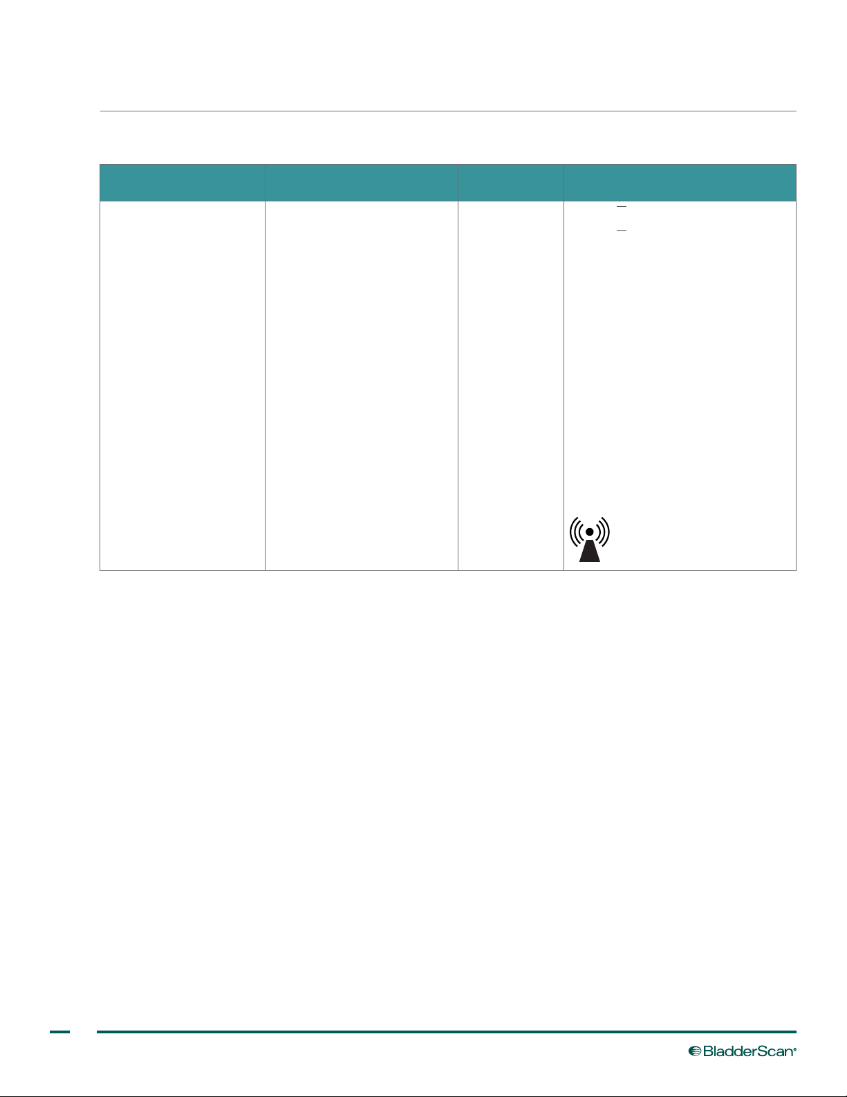
Table 12. Guidance and Manufacturer’s Declaration —Electromagnetic Immunity
The BladderScan BVI 3000 system is intended for use in the electromagnetic environment specied below. The
customer or the user of the BladderScan BVI 3000 system should assure that it is used in such an environment.
IMMUNITY TESTS IEC 60601 TEST LEVEL
Radiated RF
IEC 61000‑4‑3
3 V/m
80 MHz to 2.5 GHz
COMPLIANCE
LEVEL
3 V/m
ELECTROMAGNETIC ENVIRONMENT
– GUIDANCE
d=1.2 √P 80 MHz to 800 MHz
d=2.3 √P 800 MHz to 2.5 GHz
where P is the maximum output
power rating of the transmitter
in watts (W) according to the
transmitter manufacturer and d
is the recommended separation
distance in meters (m).
Field strengths from xed RF
transmitters, as determined by
an electromagnetic site survey,a
should be less than the compliance
level in each frequency range.
b
Interference may occur in the
vicinity of equipment marked with
the following symbol:
Note: Ut is the AC mains voltage prior to application of the test level.
At 80 MHz and 800 MHz, the higher frequency range applies.
These guidelines may not apply in all situations. Electromagnetic propagation is affected by absorption and
reection from structures, objects and people.
a. Field strengths from xed transmitters, such as base stations for radio (cellular/cordless) telephones and land mobile radios, amateur radio,
AM and FM radio broadcast and TV broadcast cannot be predicted theoretically with accuracy. To assess the electromagnetic environment
due to xed RF transmitters, an electromagnetic site survey should be considered. If the measured eld strength in the location in which the
BladderScan BVI 3000 system is used exceeds the applicable RF compliance level above, the BladderScan BVI 3000 system should be
observed to verify normal operation. If abnormal performance is observed, additional measures may be necessary, such as re‑orienting or
relocating the BladderScan BVI 3000 system.
b. Over the frequency range 150 kHz to 80 MHz, eld strengths should be less than 3 V/m.
56
Page 65
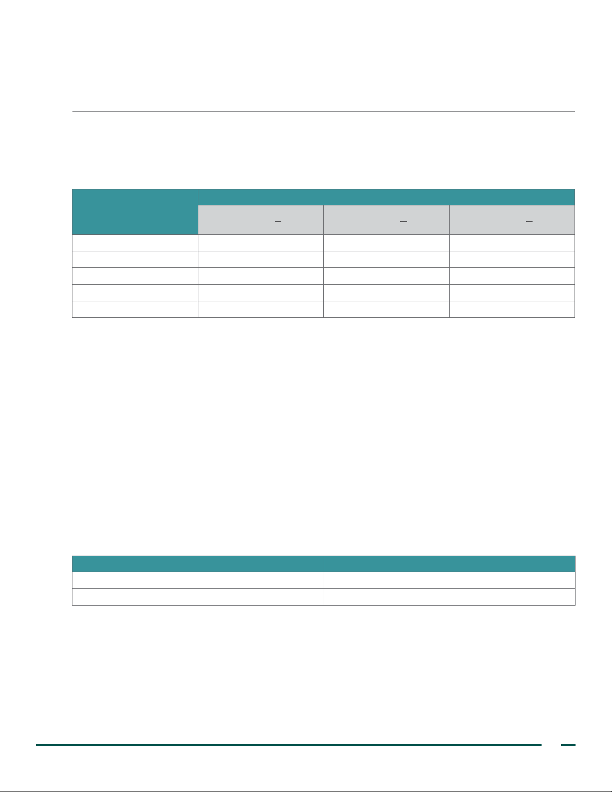
RECOMMENDED SEPARATION DISTANCES
Table 13. Recommended Separation Distances between Portable and Mobile RF Communications
Equipment and the BladderScan BVI 3000 System
The BladderScan BVI 3000 system is intended for use in an electromagnetic environment in which radiated
RF disturbances are controlled. The customer or the user of the BladderScan BVI 3000 system can help
prevent electromagnetic interference by maintaining a minimum distance between portable and mobile RF
communications equipment (transmitters) and the BladderScan BVI 3000 system as recommended below,
according to the maximum output power of the communications equipment.
RATED MAXIMUM OUTPUT
POWER OF TRANSMITTER
(W)
0.01 0.12 0.12 0.23
0.1 0.38 0.38 0.73
1 1.2 1.2 2.3
10 3.8 3.8 7.3
100 12 12 23
For transmitters rated at a maximum output power not listed above, the recommended separation distance d in
meters (m) can be estimated using the equation applicable to the frequency of the transmitter, where P is the
maximum output power rating of the transmitter in watts (W) according to the transmitter manufacturer.
Note: At 80 MHz and 800 MHz, the separation distance for the higher frequency range applies.
These guidelines may not apply in all situations. Electromagnetic propagation is affected by absorption and
reection from structures, objects and people.
SEPARATION DISTANCE ACCORDING TO FREQUENCY OF TRANSMITTER (m)
150 kHz to 80 MHz
d=1.2 √P
80 MHz to 800 MHz
ACCESSORY CONFORMANCE TO STANDARDS
To maintain electromagnetic interference (EMI) within certied limits, the system must be used with the cables,
components, and accessories specied or supplied by Verathon®. For additional information, see the System
Components & Accessories and Component Specications sections. The use of accessories or cables other
than those specied or supplied may result in increased emissions or decreased immunity of the system.
d=1.2 √P
800 MHz to 2.5 GHz
d=2.3 √P
Table 14. EMC Standards for Accessories
ACCESSORY MAX LENGTH
AC power cord 2 m (6.6 ft)
Battery charger —
Operations & Maintenance Manual: Product Specications
57
Page 66
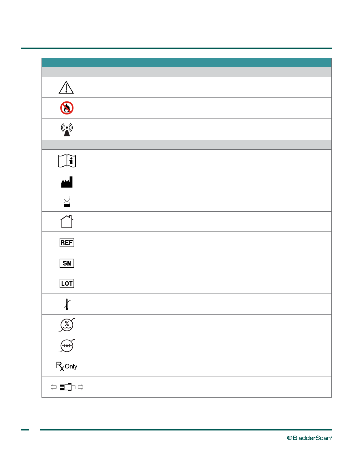
SYMBOL DIRECTORY
SYMBOL MEANING
Warnings & Cautions
Warning or Caution —Consult accompanying documents. Read instructions before
connecting or operating.
Do not incinerate
Non‑ionizing, electromagnetic radiation
Product Use & Specications
Refer to the operations & maintenance manual
Manufacturer
Use‑by date
Use in indoor, dry location only
Catalog (part) number
Serial number
Batch code
Temperature limitation
Humidity limitation
Atmospheric pressure limitation
Statement of prescription
Orient scanhead so that icon aligns with the patient's head and feet
58
Page 67
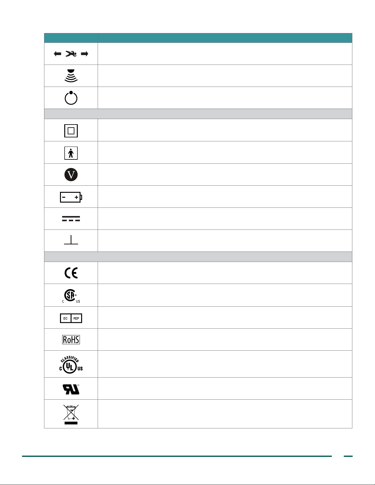
SYMBOL MEANING
Orient scanhead so that icon aligns with the patient's head and feet
Scan
Power on/off
Electrical & Power
Class II equipment
Type BF applied part
Energy Efciency Level V
Battery pack reference part number
Direct current
Ground symbol, earth terminal
Standards & Certications
CE—Marked in accordance with the Medical Device Directive (MDD)
CSA—Canadian Standards Association mark of certication to applicable standards for
electromedical equipment
EC REP—Authorized Representative in the European Community
RoHS—Meets standards for Restriction of Hazardous Substances (RoHS)
UL—Underwriters Laboratories certication mark for electrical shock, re, and mechanical
hazards only
UL—Underwriters Laboratories Recognized Component certication mark in Canada and
the United States
WEEE—Subject to waste electrical and electronic equipment regulations
Operations & Maintenance Manual: Symbol Directory
59
Page 68

GLOSSARY
TERM DEFINITION
6HRLTR6 Battery cell designation
A Ampere
AC Alternating current
Ah Ampere‑hour
C Celsius
CISPR International Special Committee on Radio Interference
cm Centimeter
CSA Canadian Standards Association
DC Direct current
EMC Electromagnetic compatibility
EMI Electromagnetic interference
ESD Electrostatic discharge
Essential performance The system performance necessary to achieve freedom from unacceptable risk
F Fahrenheit
g Gram
GHz Gigahertz
HIPAA Health Insurance Portability and Accountability Act
hPa Hectopascal
Hz Hertz
IEC International Electrotechnical Commission
in Inch
IPA Isopropyl alcohol
ISM Industrial, scientic, and medical
kHz Kilohertz
kV Kilovolt
lbs Pounds
m Meter
mAh Milliampere‑hour
MDD Medical Device Directive
MHz Megahertz
MI Mechanical index
mm Millimeter
mW Milliwatt
NiMH Nickel‑metal hydride
PIN Personal identication number
PVR Post‑void residual
60
Page 69

TERM DEFINITION
RF Radio frequency
RH Relative humidity
RoHS Restriction of Hazardous Substances
TI Thermal index
TIB Thermal index for bone
TIC Thermal index for the cranium
TIS Thermal index for soft tissue
UTI Urinary tract infection
V Volt
Vrms Voltage root mean squared
W Watt
WEEE Waste electrical and electronic equipment
Operations & Maintenance Manual: Glossary
61
Page 70

Page 71

Page 72

verathon.com
 Loading...