

Page 1
H
E
sirEBr^r??^....,..".-.,-...
ffi
H
BIack*Sf dr
METEOR
SERIES
DIGITAL FREOUENCY
COUNTERS
METEOR
1OO
METEOR
600
METEOR 1OOO
ffiHmam
O
_ _
'--a
HEY'.'-'H1e??,, W€
Instruction
Manual
Page 2
INDEX
SPECIFICATION
FRONT
PANEL
LAYOUT
BACK
PANEL
LAYOUT
MAXIMUM
INPUT
VOLTAGES
INSTALLATION
MAINS ADAPTOR/CHARGER
POWER AND
BATTERIES
RANGE
GATE
TIME
LOW FREOUENCY FILTER
INPUTS
INPUT
IMPEDANCE
TERMINATION
AND USE OF PROBES
TRIGGER
LEVEL
DISPLAYS/INDICATORS
EXTERNAL
REFERENCE
OSCI
LLATOR FACI
LITY
TRANSMITTER
FREOUENCY MEASUREMENT
RECEIVER FREOUENCY MEASUREMENT
MAINTENANCE AND REPAIR
CALIBRATION
GUARANTEE
Page
2
3
3
4
5
5
5
6
6
7
7
7
7
8
8
B
10
10
11
11
O
1983 BLACK STAR
LTD.
Page 3
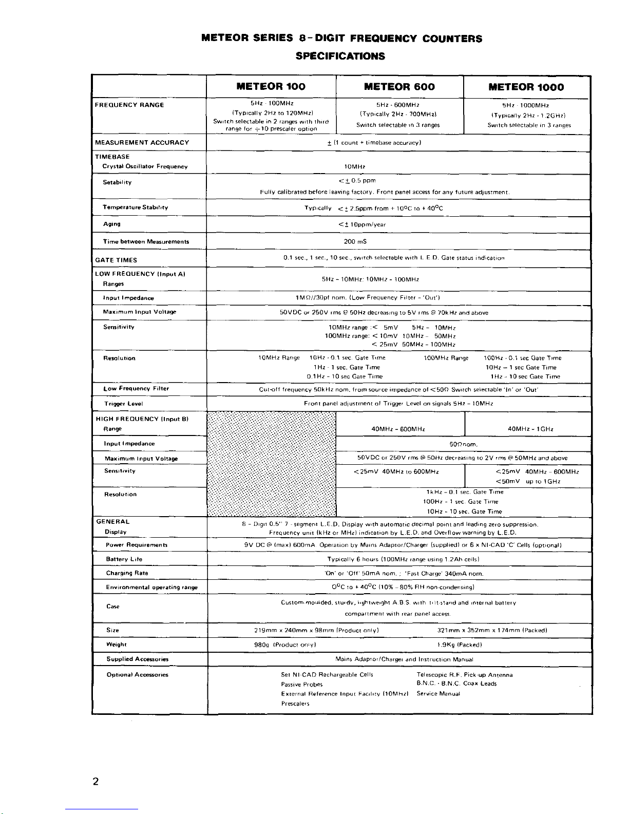
TETEOR
SERIES A-DIGIT FFEQUE]ICY
COUIiITERS
SPECtFtCATtOIrS
TETEOR lOO TETEOR
60()
TETEOR
IOOO
FREqUENCY
RANG€
5Hz 1O0MHz
{Typ,cally 2H2 ro 120MHz)
Sw
rch seleclable,^ 2 ranss
w,lh
rh,r
ranoe for
+10
prescaler
oprion
5Hz
-
60OMHz
(Tvp,cally
2Hz,
?O0MHzl
Swrrch
selectable,n 3 ranges
5Hz lOOoMHz
lTyp,cally
2Hz ' l.2cHr)
Swrrch selectable in
3
ranges
M€ASUREMENT
ACCUBACY
i
l1
count + trmebase
accuracy)
TIMEEASE
Crysl.l Os.illaior Frequ€ncy
IOMH2
<iO5PPm
Fuliy Glibrated berore
leavng tactory. Front
panel
acc6s for
any
fulure
adlusimenr
femtsrarure Stab'hay
TypLcally
<+
2.5ppm
lrom
+
lOoC
ro + 40oC
AsiD9
Tihe
hrween
Me.su.ements 20o mS
GATE
TIM€S
0.1 sec.. 1
sec., 10
sec . sw
tch selectabl€
w,th
L E D.
Care
srarss
indicat,on
LOW FBEOUENCY
llnput
A)
5Hz - 10MHzj loMHz
-
l00MH,
IMo//30pi
nom.
(Low
Frequency
F,rt€r
-
Oul')
Maxrmud
Inpur Volla$
5OVDC
or 250V
,ms
(i
50Hz decreasrns
lo 5V
rms @ 70kHz
aod above
IOMHZ range
:<
5mV
5Hz
-
l0MH2
IOOMHZ range: < lomv
IOMHZ 50MHz
<
25mV 50MHz - lOoMHZ
loMHz Range 1OH2 - 0.1 sec
Gate
T16e
1 H2
1 sec. Gare
T,me
0.1
Hz - 10
sec Gare
Time
IOOMHz Ranse lOoHz ' O.1 sec
Gate T,me
lOHz
-
1
lec Gate T,me
I Hz - l0 sec Gate Time
Low
Frquency
Filt€r
Cutttr
lrequency 50kHz nom. trom
source
impedance
ol <50o Sw,rch selecrable'ln'o. Our'
Fronr
panel
adtustment ot Tnsser
Level
on siqnali
5H2
-
loMHz
HIGB
FREOUENCY
IInput
8}
,iir,i
i
i.i.lri 4OMH?
-
600MHz
4OMHz
-
I GHz
ri iiir:tfiiiiLi.,,,,:,:.
50onom
Maxim0m
Inpur
Volta$
t'iiffi
50VDC or 25OV rm! Ld SOHZ
decreasrns
ro
2V
rms a4
50MHz and
above
<25mV
40MHz
ro 6O0MHZ
<25mV
4OMHz
6OOMH2
<5OmV up ro
lGHz
..li
lkHz-O.l sec. GareTrm€
100H2 - 1
sec Gate T,me
10Hz - l0
rec.
Gate Time
GENE BAL
a - D,9,r 0.5 7
sesmenr L.E.D. Display w,lh aulomar,c decimal
pornr
and
leadins
zero
suppress,on
Frequency
unrr {kHz or MHz) indical,on by L.E.D.
and Overflow warning
bv L.E.O.
Powe.
Sequ'remenR
9V OC Cd
(max)
6OOnA Operarion
bv
Ma,nr Adapro/Charger
Guppliedl
or 6 x
Nl-CAO C'Cells
{opt,onal)
Typicalry 6 hours
(lOOMHz
range
usins 1.2Ah cerls)
'On'or'OJf
5OmA
nom.
I
'Fasl
Charse'
340mA
nom
EnYr.ohmenral
oFrating
rans OoC ro
+
aooc
(10%
80%
aH non-condenr,ng)
Clsrom moulded,3rurdv,
l,ghtwer!hr
A B S wrrh r'11
5land and
'nternal
baller
Size
2t9mn,240mmr98mmlProdlcronlv) 321mmt352mmx174mm(Packed)
980s
lP.oducr onryl L9K9
(Pa.ked)
SuDtlicd
Ac6o'r!5 Marns Adaplor/CharWr
dnd
Insrrucrion
Ma^ual
Opr'onalAcc6ones
Ser Nl
CAD
Rechargeable
Cells
Telescopic
R.F.
Pick
up Anlenna
PasrveProb€s
INC
_a-N.C.CoaxLeads
Errernal Eelerence
Inpur Fac,l,ry
(10Mhzl
Service
Manu€r
Page 4
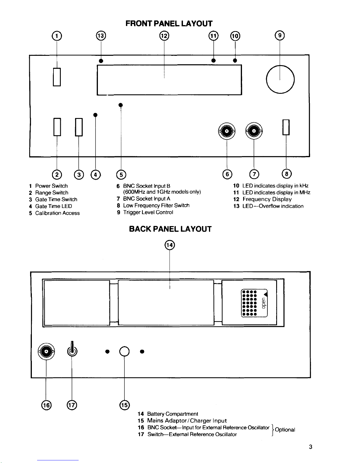
FRONT
PANEL LAYOUT
1 Power
Switch
2
Range Switch
3 GateTimeSwitch
4 GAIE
T|ME LED
5 Calibration
Access
6
BNC Socket Input B
(6O0MHz
and lGHz models only)
7 BNC Socket
Input A
8
Low Frequency Filter Switch
I
Trigger Level
Control
BACK PANEL LAYOUT
@
10
LED indicates
display
in kHz
11 LED indicates display
in MHz
12
Frequency
Display
13 LED-Overflow
indication
14
BaneryCompartment
15 Mains
Adaptor/Charger Input
16
BNC
Socket-lnput
for Eldernal Belerence
Oscillator
]
Ootional
17 Switch-External
Reference
Oscillator J
Page 5

MAXIMUM INPUT VOLTAGES
Do not
apply more
than
50V
DC or 250V
r.m.s.
sine wave
@
50Hz to
any
signal
input.
For other frequencies
see
graphs:
INPUT
A
5Hz-100MHz
250V
50
Hz
MAXIMUM
INPUT
VOLTS
RMS
5V 50kHz
10
5
100
1K 10K 100K
1M
INPUT FREOUENCY
INPUT
B
40MHz
10M 100M
Hz
-
lGHz
1000v
7Sn
100
250V
501-lz
250V
500H2
MAXIMUM
INPUT
VOLTS
RMS
10
5
2V 50MHz
100 1K
10K
100K
1M
10M
100M
1G
INPUT FREOUENCY Hz
n.l 1
10
Page 6

INSTALLATION
(a)
Insert cells
and/or
mains
adaptor.
(Back panel (14)
or
(15).)
(b)
Move
power
switch
(1
)
to
'On'.
(c)
Select
range
(2)
required, if known.
(d)
Connect signal to be measured to
appropriate
input.
((6)
or
(7).)
(e)
Select
gate
time
(3)
required.
Wait
for
one
gate
period.
(See
LED
(4).
)
MAINSAOAPTOR
The Mains
Adaptor supplied has
been specially
designed to
power
your
Meteor
Frequency
Counter.
lt
is suitable
for
the
normal mains
supply in thecountryof
purchase.
lt
is
NOT
protected
against continuous
short circuit but will
cause an
internal
nonresettable
thermal trip to operate. NO
OTHER
MAINS
ADAPTOR
(EVEN
IF
APPARENTLY IDENTICAL)
MAY
BE USED ON A
METEOR FREOUENCY
COUNTER. Such use
will invalidate the guarantee
and
may
damage the counter.
POWER AND
BATTERIES
Switch
(1).
This has three
oositions:
'Fast
Charge'will
re-charge
fully
discharged
cells at the
maximum
rate con-
sistent with not
overloading
the mains
adaptor.
There is no
provision
for
sensing
fully charged cells
and
the
user must satisfy himself that
use of this
facility
will
not
overcharge, overheat
or otherwise damage the
cells
in
use. Do
not
use in this
position
for more
than
one hour
and
then
only
on fully
dis-
charged
cells.
'Off'
disables the instrument but
allows
trickle-charging of
the
cells. Nickel-
Cadmium cells of
at least
1.2 ampere-hour
capacity may
be safely
trickle-
charged indefinitely
in
this
position.
'On'
applies
power
to
the
instrument from internal
cells or
preferentially
from
the mains
adaptor
if
used.
lf the mains adaptor is
used
with
the cells
in
place,
the
cells will
be
trickle-charged as in
'Off'.
lt is
specifically
recommended
that
primary
(dry)
cells are
not
used,
whether
alkaline or other
types.
lf,
however,
they
are used, they
MUST be
removed
before
connecting
the mains
adaptor.
Damage
caused
by
use of dry cells is
not
covered
by the
guarantee.
RANGE
Switch
(2).
This has
three
positions:
'10MHz'selects
the
10MHz range.
Any
signal of sufficient strength
may
be
read from
5Hz to 10MHz
on
this range,
but
see
'Low
Frequency Filter' and
'Trigger
Level' below. The
signal must
be
applied
to Input
A
(7).
Page 7

'100MHz'
selects the 100MHz
range.
Any
signal of sufficient strength
may be
read from
(typically)
lMHz to 100MHz on this
range, but see'Low Frequency
Filter'below.
The signal must be applied to
Input
A
(7).
'Prescaler
-
10'
(Meteor
100
only). This behaves exactly
the same as
100MHz
input, but the decimal
point
is displaced to
the
left
allowing
direct reading
when a decade
prescaler
is
used.
'600MHz'(Meteor
600 only).
This selects the 600MHz
range.
Any
signal
of
sufficient strength
may be read from
40MHz
to
600MHz
on
this
range.
The
signal must be applied to Input B
(6).
This range
may
display
a reading
in
the
absence of an
input
signal. This
is due to exceptional sensitivity, and does
not
affect operation
or
accuracy .
'1GHz'(Meteor
1000 only). This selects
the lGHz
range.
Any signal
of
suf-
ficient
strength
may be
read from
40MHz to lGHz on this range. The signal
must
be
applied
to
Input
B
(6).
This
range
may
also
display readings
in the
ab-
sence of
an
input
signal, which can be disregarded.
GATETIME
Switch
(3)
. This
switch has three
positions.
Note there
is
an
interval,
between
successive measurements. of 200ms.
'0.1s'
selects a
measurement interval of 100ms. Maximum
resolution
10H2.
'1s'
selects
a measurement
interval of
1 second.
Maximum
resolution
1Hz.
'10s'selects
a
measurement
interval of 10 seconds.
Maximum
resolution
0.1H2.
Measurement
is in
progress
while
gate
time LED
(4)
is lit.
LOW
FREOUENCY FITTER
Switch
(8).
This
has two
positions:-
'Out'
by-passes the
filter
circuitry
and
allows
full frequency spectrum on the
5Hz
to
100MHz
input.
'ln'
introduces
a low
pass
single
pole
filter into the 5Hz
to
100MHz
input. This
filter has
a
-3dB
point
of nominally
50kHz
when fed from a low impedance
source
giving
normal sensitivity to audio frequencies, with sensitivity
falling
off
rapidly
above
this.
lt's
purpose
is
to
filter
out
R. F. signals.
When a
wide band-
width instrument
is
connected to a high impedance
low-frequency
circuit,
it is
quite
common
for
parts
of
the circuit under
test
to
act as
aerials
for
any
stray
sources
of R.F.
radiation.
Because of the
high
sensitivity of
the
instrument,
these
signals
can
be counted causing errors in the wanted measurement, and
f
iltering
is
the most satisfactory solution.
r,
Page 8

t
I
I
INPUTS
Input
signal
levels
should
always be
kept to
the minimum
practicable
as under
certain
circumstances,
especially
when using
Input
A
{7),
mismatches
can
cause
unwanted line reflections
and apparent
frequency
multiplication.
All
BNC sockets
are compatible
with
50Q
plugs.
The
use
of T5rC2plugs
may
give
unreliable
or noisy
connections.
INPUT
IMPEDANCE
The impedance
of Input A is nominallylMeshunted
by
30pf.When the Low
Frequency
Filter is in
circuit,
this reduces
to
a
series
combination
of
300eand
1
Onf.
The impedance
of Input
B is nominally
50 a .
TERMINATION
AND
USE
OF
PROBES
Input
A - When measuring
frequencies
over lMHz
with a high
impedance
counter, reflections
of
the
signal
can
cause
standing
waves, miscounts
and
possible
damage
to the circuit
under test. To
prevent
this,
use a through
ter-
mination
to match
the
input
cable
or,
if
the circuit
under test cannot
stand the
load,
use
a short
(<
16
wavelength)
input
cable.
Use
of
Black Star Passive
Probes is
recommended
as
this
minimises
the
cap-
acitive loading.
The following
are available
as
optional
accessories:
AT-001
-
Xl
probe
for
any signal
up to
1MHz.
The low
capacitance
cable
minimises
circuit loading.
AT-010
-
X10 attenuator
probe
for higher
level signals,
where circuit loading
is
critical
(10M()
input
impedance)
or
for signals
over
1MHz.
No termination is
needed
and the
probe
will
accept
signals
up
to
the
maximum
frequency
of
Inout
A.
AT-110
-
A
switchable
probe
combining the features
of
both.
Input
B
Use 50Qcoaxial
cable
or the
Btack
star KBS
series
of
BNC
coax
Leads
(optional
accessories).
TRIGGER
LEVEL
The
operation
of this
control
(9)
is
analogous
to the Trigger
Level
control
on
an
oscilloscope.
lt only
operates
on
the
5Hz to 10MHz range
and enables
the
threshold
of the
squaring
circuit
to be
moved
to the
positive
or
negative
part
of
the
signal allowing
the
user
to
overcome
miscounts.caused
by
poor
or distorted
input
waveforms,
ringing,
overshoot, noise
etc.
Page 9

DISPLAYS/INDICATORS
The
gate
time
LED
(4)
is lit
for
the duration of each
measurement
period.
The
kHz
(10)
and MHz
('11)
LED's indicate the
scale factor
of
the
display. The
display
(12)
has leading
zero suppression
(for
power
conservation) and
auto-
matic
decimal
point
location.
Note
that
all
of
the
digits
on
the display may not
be
illuminated for
a
particular
frequency range/gate
time
combination
e.g.
600MHz 0.1sec
would
display at
range maximum:-
O
mxz
IIEENENE
The
Overflow
LED(13)willonly
light when
the
main LC
,
and
hence
the display,
overflows.
There is no
over-range
indicator.
Generally
most units will
read
to
at
least
11oo/o of the set range. Typical symptoms of
too high
a f
requency
input
are
extreme
variations
in reading
between one
gate
time
and the
next,
unex-
pectedly
low frequency readings
or
lack
of
input
sensitivity.
EXTERNAL REFERENCE
OSCILLATOR FACILITY
{optional)
The
External Oscillator Facility allows the
use
of an alternative
highly
stable
10MHz frequency standard to improve the
performance
of
the instrument.
The
standard should be connected
to
the
External Reference
Oscillator
lnput
(16)
on
the
back
panel.
The
input should
have
an amplitude of
5V
peak
to
peak.
The
input
impedance is
in
excess
of 1ka but
is shunted by
about 1Opf.
The input
waveform
need
not
be sinusoidal
but should be free from
glitches
and har-
monic ripple.
(A
squarewave
may have slow rise and fall times but should be
reasonably flat
and
free fromovershoot.forinstance.)
The mark/space
ratio
should be as
close as
possible
to 1:1.
The
External
Reference
Switch
(17)
selects between
internal
and external
refer-
ence
sources. This switch
must
be
returned
to the
'lnternal'
oosition
when
the
counter
is
being
used
in
the
normal mode.
TRANSMITTER
FREOUENCY
MEASUREMENT
When
measuring the
frequency
of a transmitter, the most
serious
risk
with
a Frequency Counter
is
that of
overloading
and
damaging
the inputs. lf
in
doubt, assume the counter will be overloaded
and
take
precautions
accordingly
(see
specif
ication).
I
Page 10

The
indirect
method
(no
physical
connection) of measuring transmitted fre-
quency
is
usually
the safest
and
most
convenient. Using the
Telscopic
Antenna
(optional
accessory)
plugged
into
the
appropriate input
on the count-
er,
set the
transmitter to
its minimum input
power
and
initially measure
the sig-
nal some five to
seven metres from
the transmitter
aerial.
This
is usually
ad-
equate
for
H.F.
signals. ln tests,
y4
watt
attenuated output
from
a
C.B. trans-
ceiver
gave
stable
readings when
fed
to
a 1lz
metre
base
loaded
whip antenna
about 10 metres
from
the
frequency
counter. Where low
power
transmitters
with
inefficient
aerials
are
used
(as
with some hand-held transceivers) the
sep-
aration
may need
to be
reduced
but,
in
practice,
the aerial
rarely
needs to be
closer than 1 to 2 metres. Where
a
high-power
transceiver
is
being
tested
and
the
power
level cannot
conveniently
be reduced,
use
the Telescopic
Antenna
fully closed
or
a simple
pick-up
coil
of
2 or 3 turns, 2"
in diameter
and earthed
at
one end.
With
direct
connection
of
the transmitter
to the Frequency Counter,
it
is most
important not to exceed the maximum input
voltage rating.
For example, con-
sider a 5 watt transmitter on
the
amateur 2 metre band
radiating
at 145MHz.
The
maximum input
is
2V
rms
into
50Q(lnput
B)
representing
80mW.
There-
fore the
minimum
attenuation necessary is
10
log
(5/0.08)
dB
or 18dB. ln
prac-
tice, as the Meteor
series of Frequency
Counters
are
so sensitive,
30dB
would
be safer
and still allow a comfortable
input
level of
0.5V rms. Note the
necessity
of
using
an adequately rated
attenuator
(5W
in this case). Input
A
has
a
high
input impedance
and a
suitable
'through'
matching termination should
be
used
when making
connection with coaxial
cables.
Modulated Carriers:
F.M - Narrow band
F.M. as used with
many modern
communications
trans-
ceivers
should
present
no
problems
as the
counter
essentially
averages
over the
gate
period.
Wide
band
F.M.
is rarely encountered but
should
give
acceptable
results with longer
gate
times.
A.M. - lt
is
difficult to
measure
highly modulated
A.M.
signals
as,
at some
points,
the
carrier
reaches very
low
levels.
Further,
the mean
power
may
con-
siderably exceed the nominal
power,
so
great
care must be
taken
when
cal-
culating attenuation for
direct
coupling. lf
the
signal
can be
measured
when
free
from modulation,
the
results
are
always
more
predictable.
S.S.B. - Single
side band transmissions suppress the
carrier which therefore
cannot easily be measured. lf an
audio
signal
generator
is available, transmit
a
lkHz tone
and
note
the
measured frequency
indicated
on the
counter. Sub-
tract lkHz from this reading for true carrier frequency
with
upper
side band
transmission
{and
vice versa
for
lower side band).
C.W. - Measurement is
straightforward.
lf
using a
morse
sender,
the
key must
be kept
depressed.
Page 11

RECEIVER
FREOUENCY
MEASUREMENT
Direct measurement
of
received
frequency in
a superhet. receiver
is not norm-
ally
possible.
lt is
easier to measure the local
oscillator frequency
and allow for
any
l.
F. offsets.
For example,
a conventional receiver
with
455kHz l. F. and the
local
oscillator
set
high
would, when
tuned to
B. B.
C.
Radio
Three on 1.206MH2,
exhibit a measureable
local
oscillator frequency
of 1.661 MHz.
lf the l.F. fre-
quencies
are not
known, find
a station
of
known frequency
and
measure
the
local
oscillator.
Retune to
the unknown
station and measure
the local
oscillator
again.
The
difference between
the two measurements
is the
same as the dif-
ference
between
the
frequencies
of the two stations.
Some
modern multi-band,
multi-mode
receivers
use different
l.F.
frequencies
depending
on the band
selected which may render
this technique difficult
or
impractical.
Another method
is to tune in
the wanted
station then tune a signal
generator
-
feeding
a small
aerial
near
the
set - using
minimum
power,
until an audible
beat
with
the wanted
station is heard, then measure
the frequency
of
the
signal
generator.
By using low
power,
the chance
of spurious
beats, whistles or
'birdies'due
to harmonics
or
poor
image rejection in
the receiver,
is reduced.
The
two strongest
beats will normally
be at the wanted frequency
and
the
image frequency
(offset
by twice the
l.F.). The beat
at
the
wanted f requency
should be stronger
and
require
less injected
signal.
MAINTENANCE
AND
REPAIR
The manufacturer,
or the
appointed agents overseas,
will repair
and
calibrate
any
instrument
developing
a fault.
See the
guarantee
card for full
details but
always observe
the following
points:-
1. Remove
batteries
before returning
product
2. Do NOT return
any accessories.
3.
Pack
product
very carefully.
Whenever
possible
retain
original
packing
for this
purpose.
Where
owners wish
to undertake their
own repairs
and calibration. this
should
be carried
out by
skilled
personnel,
with
access to
precision
equipment,
working
in conjunction
with the
Service Manual which
can be
purchased
f
rom
the
manufacturer
or their overseas
aoents-
Page 12

CALIBRATION
For
optimum
accuracy,
the instrument
requires
calibration
from
time
to
time.
How frequently
will
depend
on the
user
and
application
but
once
every twelve
months
would
normally
be
adequate.
provision
for
this is
made
on the front
panel.
Use of
a nylon
trimmer
tool is
recommended.
lf a screwdriver
is
used, it
MUST
be insulated
from
the front
panel,
as a short
circuit
from
the trimmer
to
ground
will
cause
damage.
The most
convenient
accurate
frequency
reference
is
usually
a
precise
transmitted
carrier
wave.
In the
U.K., Rugby
(60kHz)
and
Droitwich
(currently
200kHz,
changing
to 198kHz
in
1986)
are suitable
trans-
missions.
'off-Air'
frequency
standard
receivers
for
this
purpose
are com-
mercially
available.
GUARANTEE
For
guarantee
details
please
refer
to
separate
card inserted
in
this manual.
 Loading...