

Page 1
February 2021
Installation and Operation Manual
Blackmagic
Web
Presenter HD
Blackmagic Web Presenter HD
Page 2

English
Welcome
Thank you for purchasing your Blackmagic Web Presenter HD!
Blackmagic Web Presenter plugs directly into any SDI equipment, converts the signal
into H.264 and lets you stream it on popular streaming services such as YouTube Live,
Facebook Live and Twitch. You can also transmit broadcast quality video point to point
using an optional ATEM Streaming Bridge. This makes transmission of professional video
toremote locations easy using the internet!
This instruction manual shows you everything you need to know to get started with
Blackmagic Web Presenter and how to use all the features and controls, including how to
set everything up for YouTube Live, Facebook Live, Twitch, Zoom, Skype and more.
Check the support page on our website at www.blackmagicdesign.com for the latest
version of this manual and for updates to your Blackmagic Web Presenter HD’s internal
software. When downloading the software, be sure to register with your information so
wecan keep you updated when new software is released.
We are continually working on new features and improvements, so we are keen
hear from you!
Grant Petty
CEO Blackmagic Design
Page 3

Contents
Getting Started 4
Using Web Presenter HD’s Front Panel 6
LCD Display 8
Using the Monitor Output 9
Using Web Presenter Setup 14
Live Stream Tab 15
Setup Tab 16
Network Settings 17
Setting Internet Sharing forDirectStreaming 17
Streaming Using Your Smartphone 18
Using Blackmagic Web Presenter HD as a Webcam 18
Setting up Open Broadcaster 18
Creating Video Links with ATEM Streaming Bridge 21
Teranex Mini Rack Shelf 21
Updating the Internal Software 22
Developer Information 23
Blackmagic Web Presenter Ethernet Protocol 23
Protocol Blocks 25
Help 36
Regulatory Notices 37
Safety Information 38
Warranty 39
3Blackmagic Web Presenter HD
Page 4
Getting Started
Getting started with your Blackmagic Web Presenter HD is quick and easy! All you need to do
isconnect power, connect video and audio, connect the unit to your computer, then connect to
the internet.
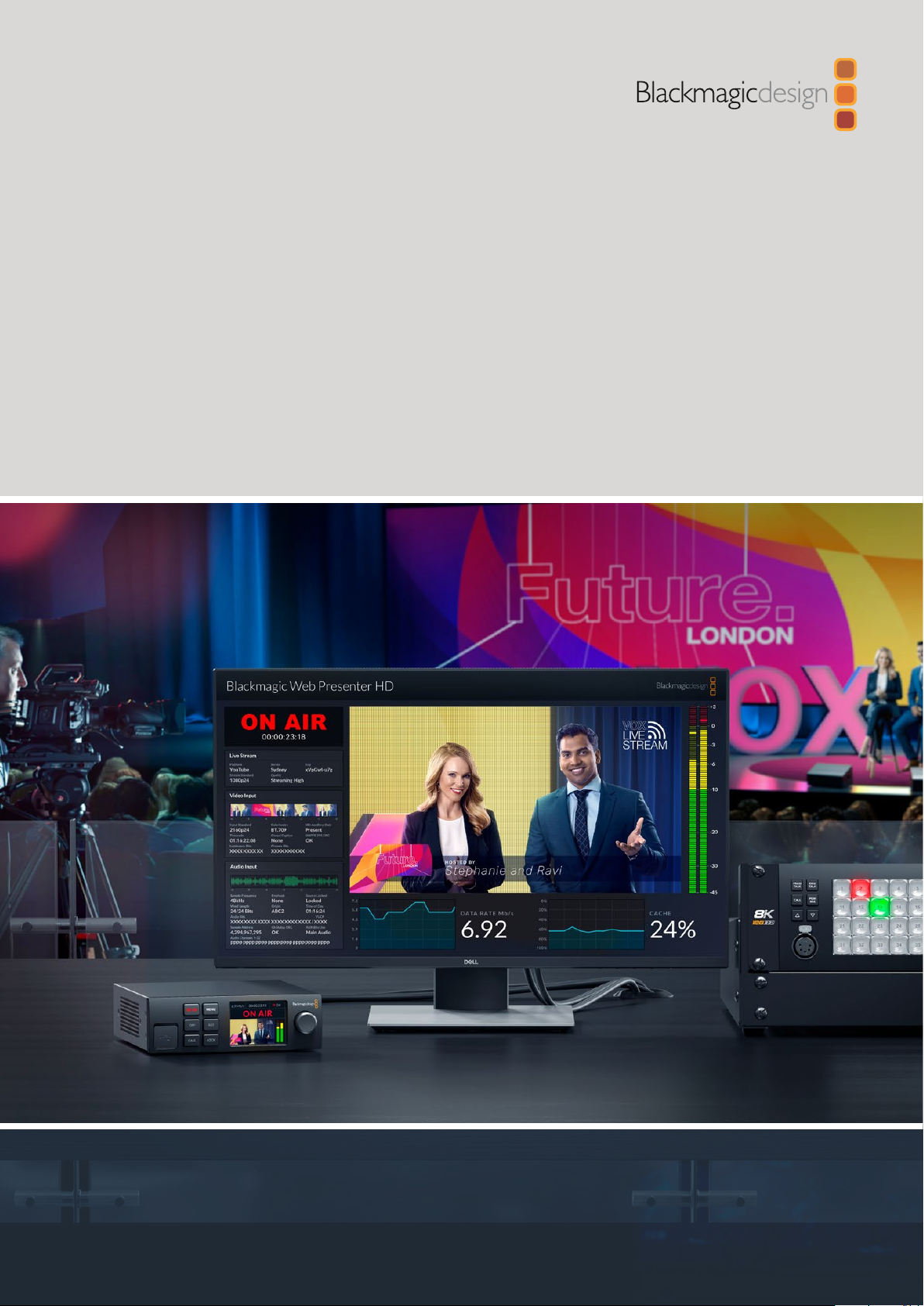
Blackmagic Web Presenter HD front panel
Connecting Power
Plug a standard IEC power cable into your Blackmagic Web Presenter HD’s powerinput on the
rear panel.
Web Presenter HD can be powered using the IEC or 12V DC power input
Web Presenter HD also has an additional 12V DC power input. You can use this input if you want
to connect external power or redundancy via an external power supply, for example a UPS or
external 12V battery.
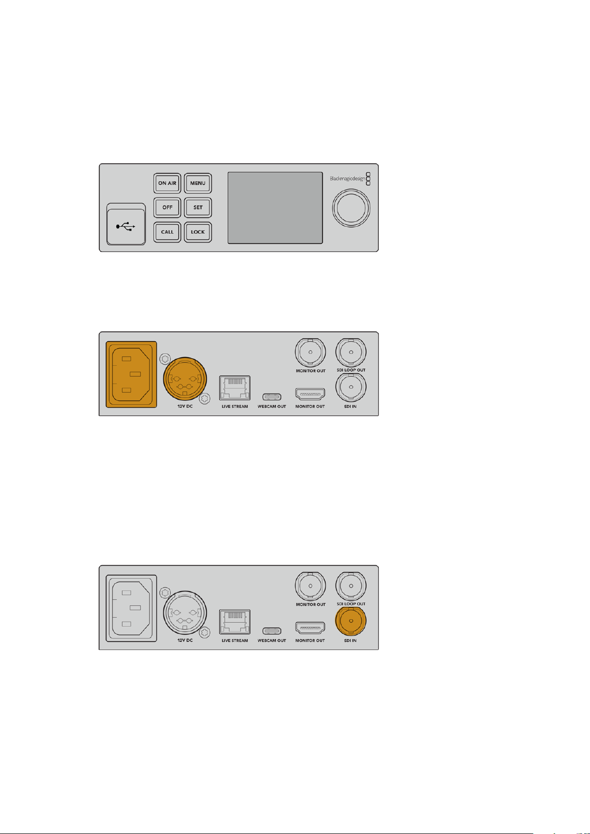
Connecting Video and Audio
Plug your video source into Blackmagic Web Presenter HD’s SDI input. When video is
connected it will be displayed on your web presenter’s built in LCD. Audio is embedded with
the video on the SDI video signal and you can confirm it by observing the audio meters
on the LCD.
Connect video to your Blackmagic Web Presenter’s SDI input
Blackmagic Web Presenter HD supports 12G-SDI and will automatically switch between HD
and Ultra HD all the way up to 2160p60 when the video input changes. This means you can
input virtually any video signal and it will convert down to 1080p.
4Getting Started
Page 5
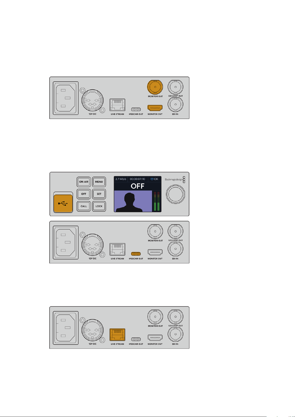
Connecting a Monitor
Plug your HDMI television or SDI monitor into one of the monitor outputs. This lets you monitor
your broadcast and observe important status information that updates constantly with your
video stream. For more information on how to use the monitor output, refer to the ‘Using the
Monitor Output’ section.
Connect a monitor to your web presenter’s monitor output
Connecting to a Computer via USB
Connect your Web Presenter HD to your computer using the USB-C port on the front or rear
panel. These USB ports are used for updating the unit and configuring it with the Blackmagic
Web Presenter Setup utility. Once you have configured your Web Presenter for the first time,
you can then disconnect the unit from the computer.
Connect your Blackmagic Web Presenter HD to your
computer using the USB port on the front or rear panel
Connecting to the Internet
Connect your Blackmagic Web Presenter HD to the internet by plugging a network cable from
the ‘live stream’ Ethernet port to an internet router or a network switch.
Connect your Blackmagic Web Presenter HD to your
network via the Ethernet port on the rear panel
5Getting Started
Page 6
Setting up a Live Stream
You can now setup your Web Presenter HD to stream via any streaming platform such as
YouTube Live, Facebook Live, Twitch and more. For this example, we will set up for a YouTube
Live stream.
1 Copy your stream key from your YouTube Studio account.
2 Download the Blackmagic Web Presenter Setup utility from
www.blackmagicdesign.com/support and install it on your computer.
This software lets you configure streaming settings for the first time.
3 Launch the Blackmagic Web Presenter Setup utility and go to the ‘live stream’ page.
4 Set the platform to YouTube and the server to ‘primary’. Paste your YouTube stream key
into the ‘key’ field and select a streaming quality. Click ‘save’.
5 You’re now ready to start streaming to the world! Click the ‘on air’ button or press the
‘on air’ button on the unit’s front panel. When your production has finished, press the
‘off’ button to stop your broadcast.
For information setting up a live stream on a different service such as Facebook Live or Twitch,
see the ‘Using a Live Streaming Service’ section.
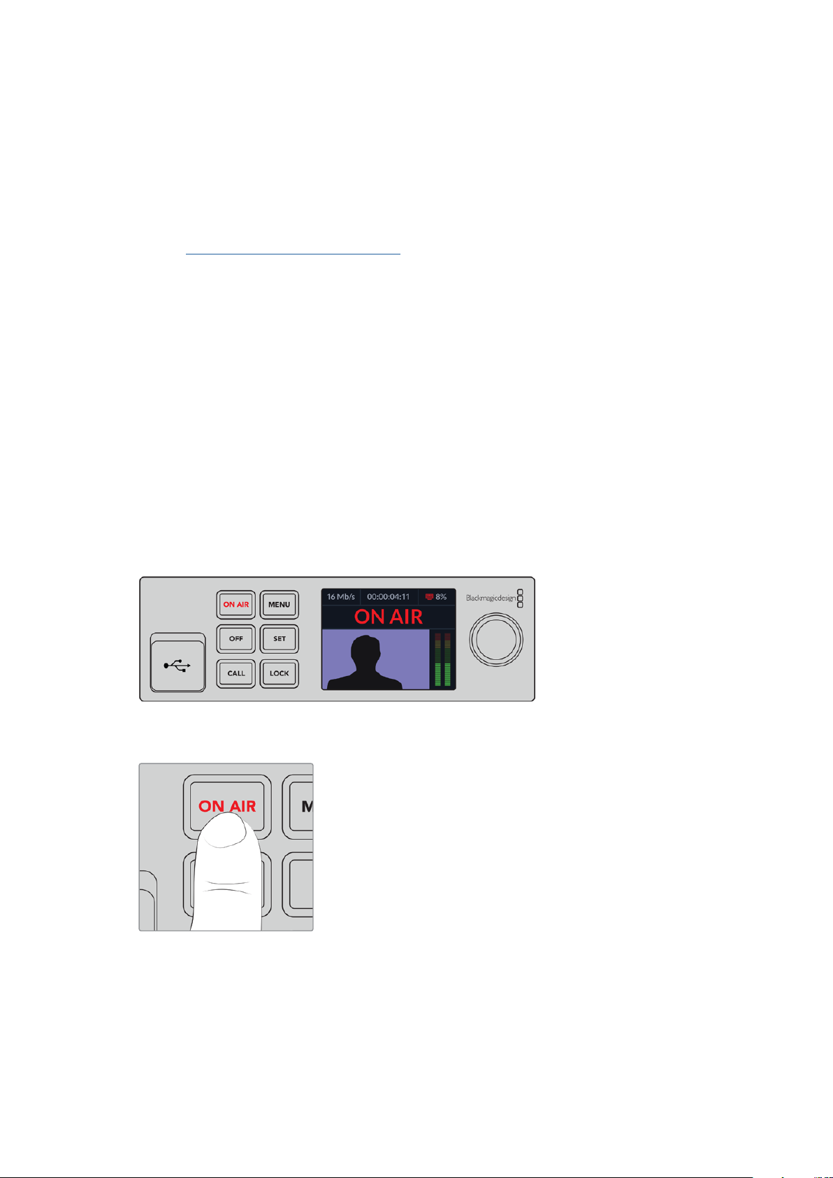
Using Web Presenter HD’s Front Panel
Use Blackmagic Web Presenter’s front panel controls to start and stop streaming and
change settings.
On Air - To start and stop streaming, simply press the ‘on air’ button. The button will highlight
red while streaming on air.
If the on air button flashes, it means a live stream has failed to start, or has stopped
unexpectedly. This might be due to a problem with your internet connection or streaming
settings. Check that your internet connection is working and your streaming settings
are correct.
6Using Web Presenter HD’s Front Panel
Page 7
Off - To stop streaming, press the ‘off’ button.
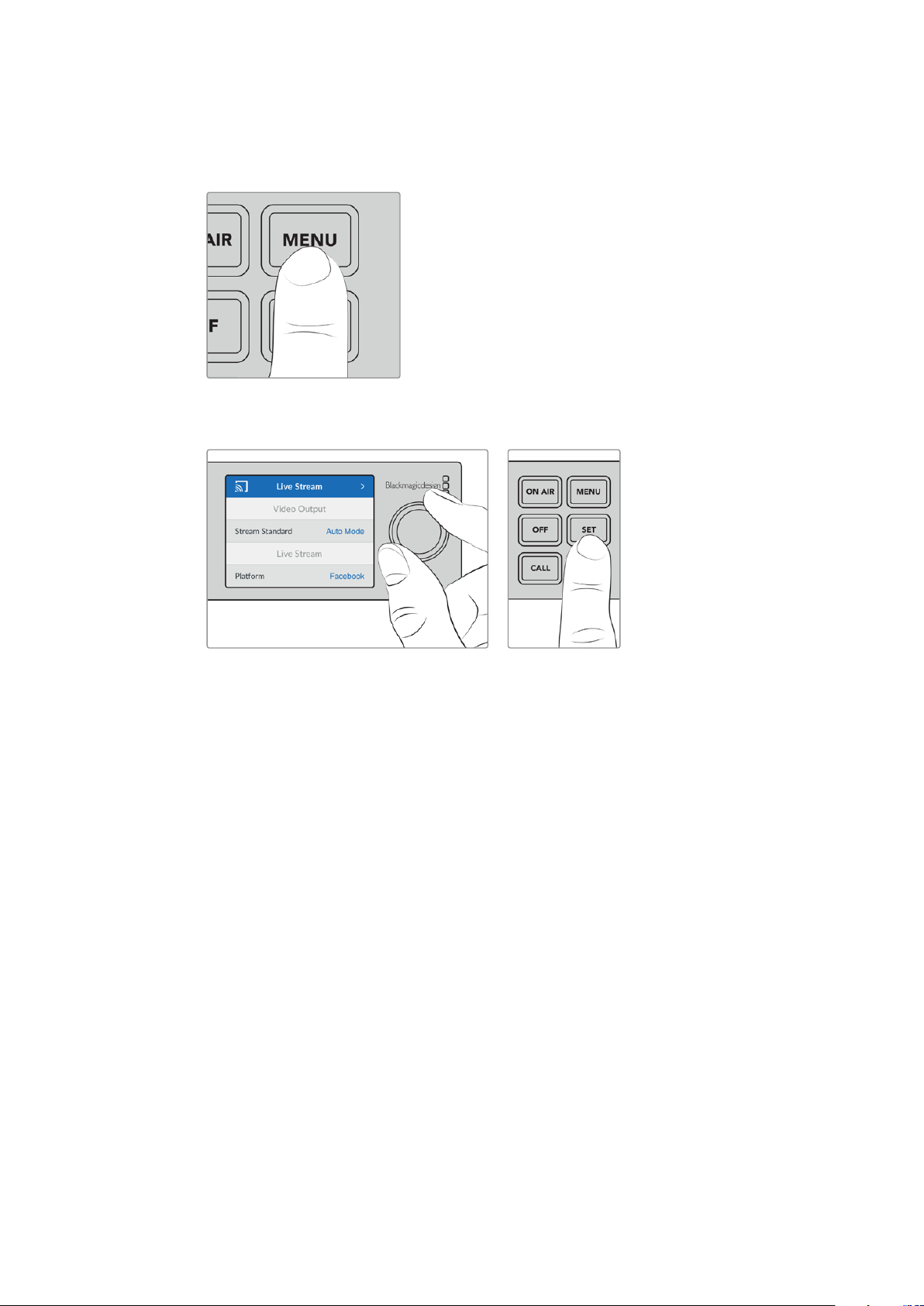
Menu - Press the menu button to open the settings on the LCD.
To change a setting:
1 Rotate the knob to select the setting you want to change, then press ‘set’.
2 Rotate the knob to change your setting.
3 Press ‘set’ again to confirm the change.
Press the menu button to step back through the menu items and return to the home screen.
Call - This feature will be enabled in a future update.
Lock - Press and hold this button for 1 second to lock the panel. This disables the buttons,
preventing anyone from accidentally going on air or stopping a stream. The button will
illuminate red when active.
Press and hold for 2 seconds to unlock the panel.
7Using Web Presenter HD’s Front Panel
Page 8
LCD Display
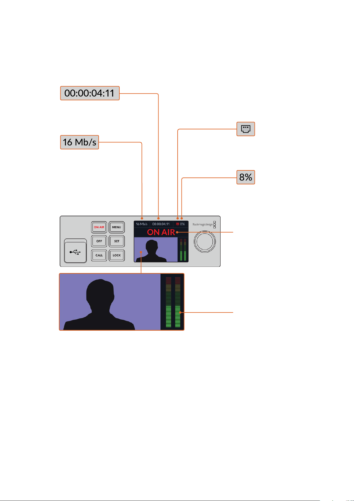
The home screen is the first feature you’ll see when you power up your Web Presenter HD.
The home screen displays important information, including:
Duration Counter – Shows the
current duration of your live
stream. The counter will start when
you press the ‘on air’ button.
Internet Connection –
Asmall icon is displayed
Data Rate – Shows
the data rate of the
encoder whether or
not your Presenter HD
is streaming. You can
connect your video
source to an input and
quickly see the bit rate
required to stream
your live video feed.
whenyour Web Presenter HD
is connected to the network.
Cache – Showsthe
percentage of Web Presenter
HD’s built in memor y cache
that is currently in use.
Video Monitor – Displays the input video
source that is connected to Web Presenter HD.
On Air Status – A bright red on
air indicator will be displayed
when your live stream is running.
When the unit is standing
by ready to start streaming
‘off air’ will be displayed.
Aflashing red and white on
air indicator means that there
has been an interruption
during the stream, such as a
slow internet connection.
Audio Meters – Displays
the audio levels of the
video source connected
to Web Presenter HD.
8Using Web Presenter HD’s Front Panel
Page 9
Internet Connection Icons
A blue Ethernet icon is displayed when an Ethernet cable is connected and the
Ethernetconnection will be used for streaming.
A red Ethernet icon is displayed when on air and streaming via Ethernet.
A blue smartphone icon is displayed when a tethered smartphone’s internet
connectionwill be used for streaming.
A red smartphone icon is displayed when on air and streaming via a tethered
smartphone.
TIP If no icon is displayed then your Web Presenter HD is not connected
to the network.
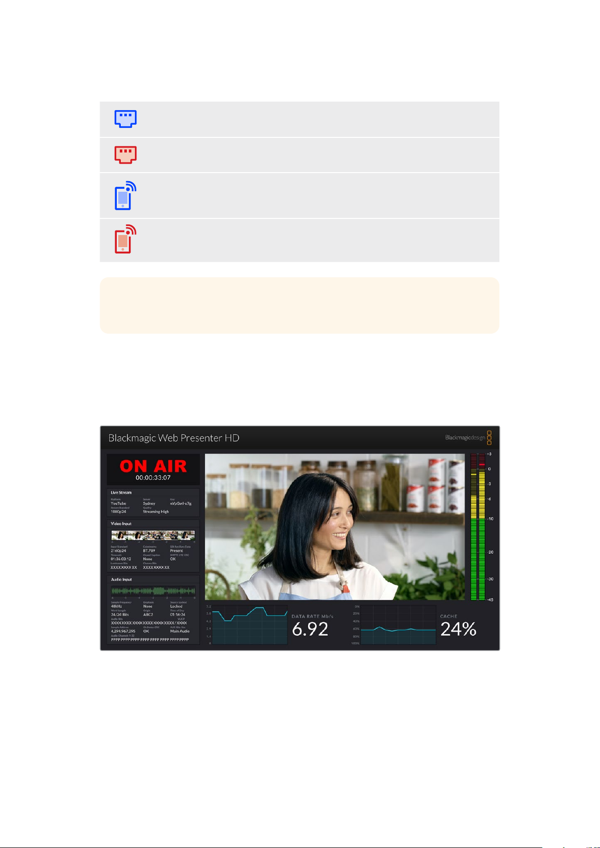
Using the Monitor Output
The monitor output lets you monitor the video input, audio levels, on air status, data rate and
cache levels, plus technical information about the SDI input.
The monitor out on Web Presenter HD provides comprehensive
information including data rate and cache status.
9Using the Monitor Output
Page 10
The monitor output display is made up of 8 panels. Below is a description of each panel and the
information it displays.
Input View
The main panel displays your current video input from the connected SDI video source.
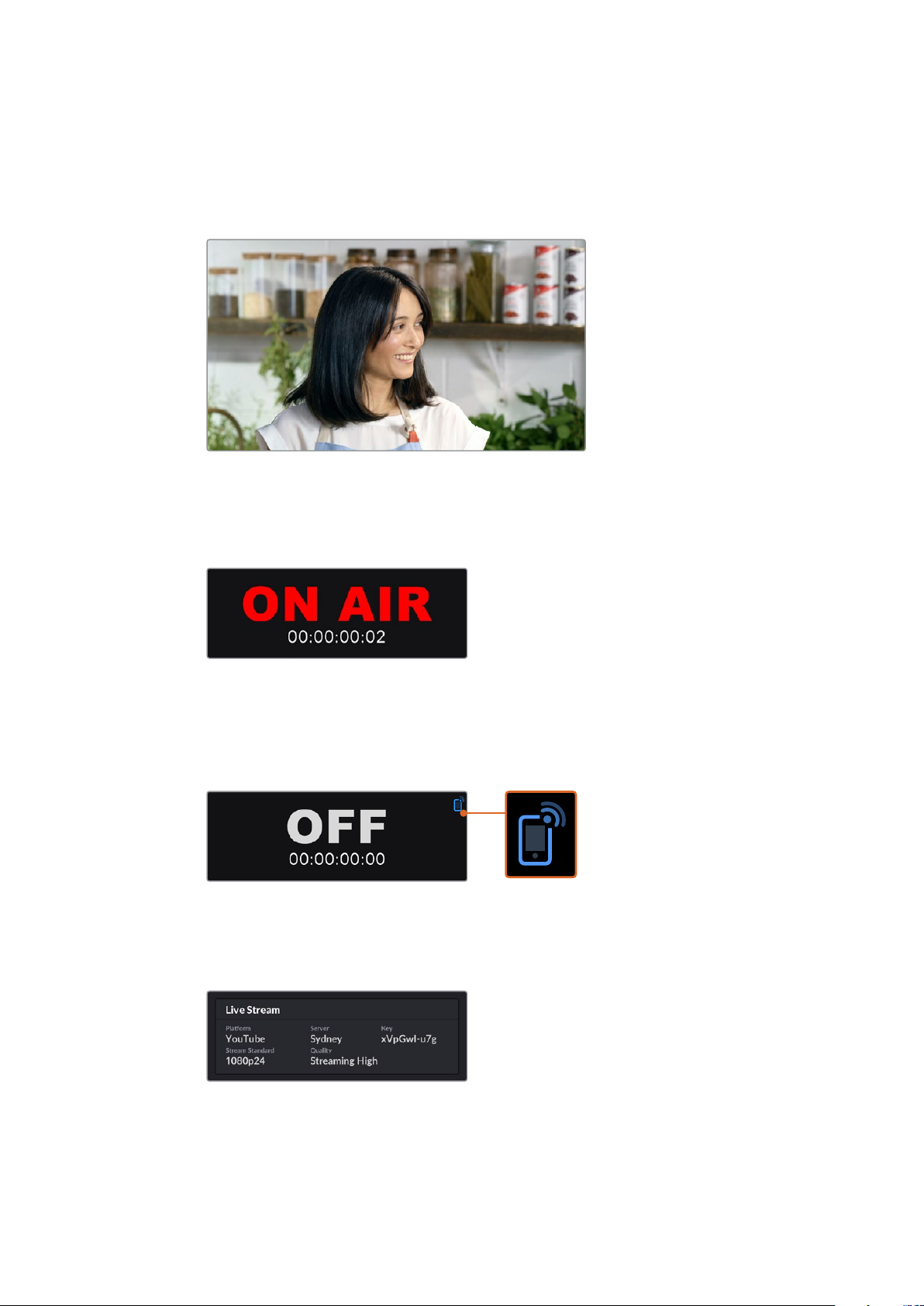
On Air Status
Prior to streaming, the on air status indicator will display ‘off’ to let you know
Web Presenter HD is standing by and ready to broadcast. When streaming begins,
theindicator will display a bright red ‘on air’ status until streaming is stopped.
Underneath the on air indicator is the duration counter. When you press the on air
button on the Web Presenter HD, the duration counter will start running.
If your Web Presenter HD is off air but will stream via a tethered smartphone, the ‘off’
indicator includes a blue smartphone icon in the corner. When on air, the smartphone
icon will illuminate red.
Live Stream
The live stream panel displays information about your live stream settings. This includes
the streaming platform, server and the first 10 digits of your streaming key. It also
displays the stream resolution and quality settings.
10Using the Monitor Output
Page 11
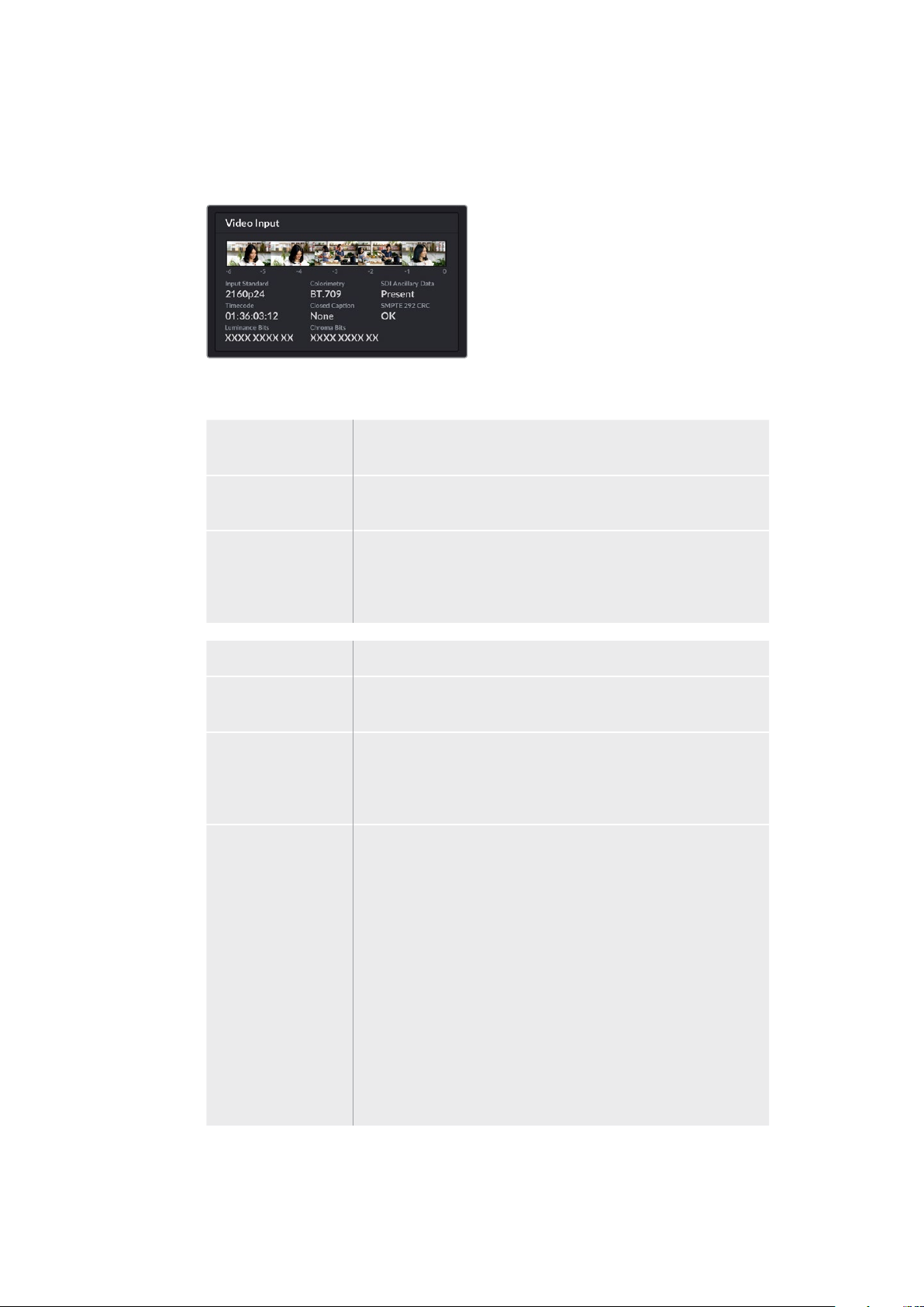
Video Input
The 5 mini viewers at the top of the video input panel show the previous 6 seconds of
your live stream, each mini viewer represents 1.2 seconds of streaming time.
Below the mini viewers you can view detailed technical information about the video
input source connected to your Web Presenter HD’s SDI input.
Input Standard Displays the resolution and frame rate of the SDI video input.
Web Presenter HD supports up to 2160p60.
Colorimetry Shows the color space of the SDI video input. Web Presenter HD
suppor ts Rec.601, Rec.709 and Rec.2020 color spaces.
SDI Ancillary Data Ancillary data is data carried in the SDI video input that is in
addition to video. This includes embedded audio, timecode and
closed captions. If your SDI input includes ancillary data then
‘Present’ will be displayed.
Timecode Displays the timecode from the SDI video input source.
Closed Captions If your SDI video input includes Closed Captions the format will be
displayed here. CEA-608 and CEA-708 formats are supported.
SMPTE 292 CRC This is an error checking function for SDI video. If your
Web Presenter HD detects a problem in the SDI video input it will
display an error. CRC errors are usually caused by a faulty SDI cable
or a cable that is too long.
Luminance Y Bits
and Chroma Bits
The indicators for ‘luminance y bits’ and ‘chroma bits’ show you
the activity of the SDI video input signal. Each letter represents the
state of one bit of the video signal.
X - An ‘X’ indicates a constantly changing bit.
L - A low bit.
H - A high bit.
SDI offsets are subtracted to make it easy to understand. For
example, all bits are low when video is black.
Generally, all 10 bits for your SDI video input will show ‘X’ to mean
all the bits on your video stream are changing constantly. If your
SDI input is 8 bit video, the two rightmost bits will always be ‘L’ as
they don’t have any data. If a bit stays ‘L’ or ‘H’ when you expect
itto be ‘X’, this indicates a ‘stuck bit’ and could be the result of a
fault in the upstream video.
11Using the Monitor Output
Page 12
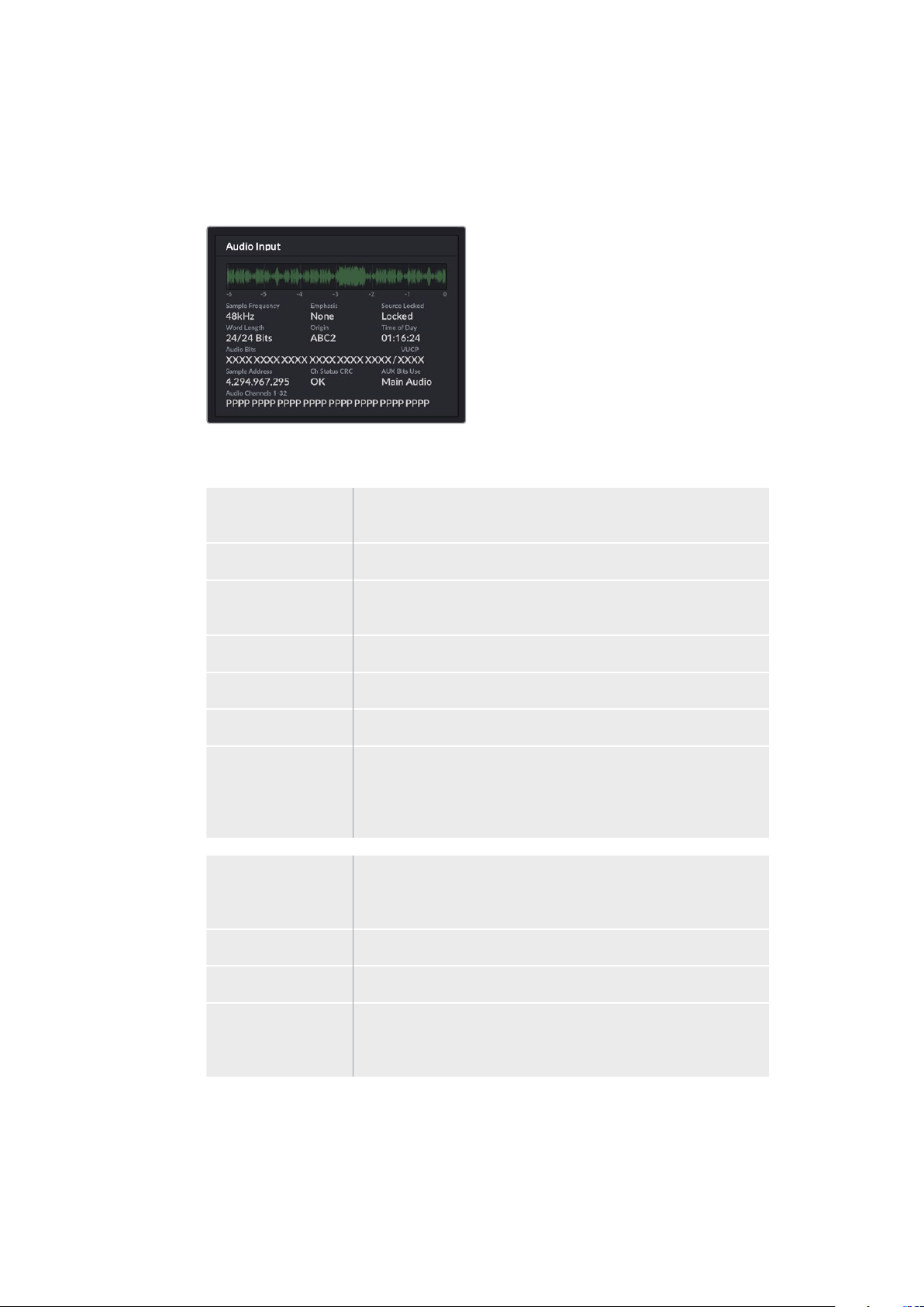
Audio Input
The audio waveform display at the top of the audio input panel shows the audio
information for the past 6 seconds of your live stream. This is continually updated and
scrolls from right to left.
Below the audio waveform display you can view detailed technical information about
the audio input.
Sample Frequency Displays the sample frequency rate of the audio embedded
in the SDI input.
Emphasis Indicates if your audio source has its emphasis option enabled.
Audio Source Lock Indicates whether the audio source frequency is locked to an
external reference source.
Word Length Shows the bit depth of the audio embedded in the SDI input.
Origin These four characters indicate the channel origin.
Time of Day Free run timecode.
Audio Bits Similar to ‘luminance y bits’ and ‘chroma bits’. An ‘X’ means a
constantly changing bit. If a ‘L’ or ‘H’ is displayed this indicates
a ‘stuck bit’ and may mean the the audio signal bit depth is less
thanexpected.
VUCP Reading VUCP bits from left to right: the ‘V’ bit indicates ‘valid’,
‘U’is the ‘user’ bit, ‘C’ is the ‘checksum’ bit, and ‘P’ is for ‘parity’.
This field is like ‘audio bits’.
Sample Address Audio sample counter.
AUX Bits Use Indicates whether AUX bits are used for main audio.
Audio Channels 1-32 Each digit represents an embedded audio channel on the SDI input.
A ‘P’ shows that an audio channel is in use and a ‘-’ means that
there is no audio on that channel.
12Using the Monitor Output
Page 13

Data Rate Display
The data rate display shows the current data rate of of the encoder over the past
60 seconds. The data rate is measured in megabits per second. This indicator runs
consistently, even when off air, so you can accurately gauge your bandwidth before
going on air.
Cache Display
The cache display shows the percentage of Web Presenter HD’s built in memory buffer
that is currently in use and the graph shows the amount used over the past 60 seconds.
The cache is a small amount of internal memory that continuously records and plays the
program output. It acts as a safety measure if the streaming data rate decreases below
a level able to sustain video.
The variable nature of the internet is mostly due to network activity or wireless signal
strength, so if the broadcast data rate decreases, the buffer data will increase
accordingly. If the connection speed becomes slow enough that it cannot support the
video stream, the cache will fill with video frames to compensate. However, once the
cache is 100% full, the video stream will be compromised, so you will want to avoid a
full cache where possible. You can run a test by connecting a video feed and watching
the cache display in the monitor output without having to start the stream. If the cache
frequently approaches 100%, choose a lower quality in the live stream settings.
Audio Meters
You can monitor the levels of your audio source using the audio meters. These can be
set to display either PPM or VU levels in the Web Presenter HD’s menu settings. If your
audio levels are too high the meters will illuminate red and may mean that the audio in
your live stream could become distorted or clipped. Ideally try to keep your audio
towards the top of the green section and occasionally in to the yellow section.
13Using the Monitor Output
Page 14

Using Web Presenter Setup
When your Blackmagic Web Presenter is connected to a network, any computer connected to
the same network can be used to control your Web Presenter remotely. With Blackmagic Web
Presenter Setup, you can access the same controls and settings that are available on the unit’s
front panel.
14Using Web Presenter Setup
Page 15

Live Stream Tab
Video Output
Stream Standard
Click on the ‘stream standard’ menu to select the video resolution setting for your
stream. Youcan choose from 720p25 up to 1080p60.
Settings
If you have custom streaming settings, for example an XML file from a Blackmagic
ATEM Streaming Bridge, you can import them by clicking the ‘load streaming
settings’ button.
For more information on creating custom settings and connecting to ATEM Streaming
Bridge, refer to the ‘Creating Video Links with ATEM Streaming Bridge’ section later in
this manual.
Live Stream
Platform
Click the ‘Platform’ menu to select the streaming platform for your broadcast. Options
include YouTube, Facebook and Twitch. If you have imported custom streaming settings
they will also appear in the platform list.
Server
Select the server that is closest to your location by selecting it from the list. The server
list will vary depending on your chosen streaming platform.
Key
Enter the streaming key that has been assigned to your broadcast from the streaming
platform. For more information on obtaining a streaming key, see the ‘Getting a
StreamKey’ section.
Quality
Select the streaming quality:
• HyperDeck High 45 to 70 Mb/s
• HyperDeck Medium 25 to 45 Mb/s
• HyperDeck Low 12 to 20 Mb/s
• Streaming High 6 to 9 Mb/s
• Streaming Medium 4.5 to 7 Mb/s
• Streaming Low 3 to 4.5 Mb/s
The data rate used by the quality setting will change depending on the video standard
Web Presenter HD is using. For example, if you select ‘streaming high’ quality and are
running at 1080p24 then it would use the 6 Mb/s data rate.
The data rates used on HyperDeck High are 45 to 70 Mb/s, the rates for HyperDeck
Medium are 25 to 45 Mb/s and the data rates used for HyperDeck Low are 12 to 20
Mb/s. The streaming data rates are lower to allow for transmitting the data over the
internet, so the data rate for Streaming High is 6 to 9 Mb/s, the data rate for Streaming
Medium is 4.5 to 7 Mb/s and the data rate for Streaming Low is 3 to 4.5 Mb/s.
You will notice that each setting has 2 data rates mentioned. The lower number is used
for the lower frame rates of 24p, 25p and 30p, while the higher data rates are used
when you are running higher frame rates of 50p and 60p. It’s also worth noting that the
default setting for the streaming quality is Streaming High 6 to 9 Mb/s, as this gives a
very high quality streaming channel.
15Using Web Presenter Setup
Page 16

Off and On Air buttons
You can start or stop a live stream by using the ‘off’ and ‘on air’ buttons. The ‘on air’ button
illuminates red when a live stream is in progress.
Setup Tab
Name
If you want to rename your Web Presenter HD, type a new name into the box and click ‘save’.
Language
Lets you change the unit’s language setting.
Software
Displays Web Presenter HD’s current software version.
Audio Meters
Use the menu to choose the type of audio meter to display. Choose from VU -18dBFS,
VU-20dBFS, PPM -18dBFS or PPM -20dBFS reference levels.
Network
These settings allow you to configure options such as choosing between connecting to a
network over DHCP or using a static IP address. For more information on connecting your
WebPresenter HD to a network, refer to the ‘network settings’ section.
Connection Priority - When Ethernet and a mobile phone are both connected to
theWeb Presenter, this setting lets you choose which connection will be used for
streaming. For more information on mobile tethering, refer to the ‘streaming using
yoursmartphone’ section
16Using Web Presenter Setup
Page 17

Reset
Reset your Web Presenter HD by clicking the ‘factory reset’ button.
Network Settings
Your Web Presenter HD can connect to the network using a static IP address or by using DHCP.
DHCP - will automatically set an IP address for your unit and connect it to your network without
any settings changed.
The dynamic host configuration protocol, or DHCP, is a service on network servers and routers
that automatically finds your Web Presenter HD and assigns an IP address. DHCP makes it easy
to connect equipment via Ethernet and make sure that IP addresses do not conflict with each
other. Most computers and network switches support DHCP.
Static IP - If you want to set the IP address yourself, simply set the protocol setting to ‘static IP’
and change the IP settings manually.
A static IP address is one that won’t change even if your Web Presenter HD is rebooted.
Using a static IP address might be necessary if your connecting your Web Presenter HD to a
corporate network. If you have a network administrator, it’s possible your network might have
custom IP addresses for all the equipment connected to it. It’s best to check with your network
administrator if they are managing your computers and network in your company.
Setting Internet Sharing
forDirectStreaming
If you are unable to plug Web Presenter HD directly into a network switch or internet router,
youcan share your computer’s internet connection with Web Presenter HD through its
Ethernet port.
To set up Blackmagic Web Presenter HD for direct streaming:
1 Set your Web Presenter HD to use DHCP.
2 Configure your computer to share its internet connection through its Ethernet port.
Mac: in System Preferences, click ‘sharing’ then select ‘internet sharing’ from the
‘service’ list. In the ‘share your connection from’ menu, choose ‘wi-fi’ if your Mac is
connected to the internet over wifi. In the ‘to computers using’ list, select ‘ethernet’.
Inthe ‘service’ list, tick the ‘internet sharing’ checkbox. When you are asked if you are
sure you want to turn on internet sharing, click ‘start’.
Windows: in the Windows search box, type ‘view network connections’ and press
enter. Right click on the internet connection and select ‘properties’. On the ‘sharing’ tab,
tick ‘allow other network users to connect through this computer’s internet connection’.
Select a network connection in the menu then click ‘OK’.
3 Plug Web Presenter HD into your computer’s Ethernet port. After a few seconds,
DHCPassigns an IP address to Web Presenter HD.
4 Confirm your Web Presenter HD is connected to the internet via Ethernet by observing
Ethernet icon in the top right corner on the unit’s LCD screen.
17Setting Internet Sharing forDirectStreaming
Page 18

Streaming Using Your Smartphone
Blackmagic Web Presenter is able to stream by tethering to your smartphone. This means you
can stream to the world from any location where your smartphone has a cellular connection.
To set up mobile tethering:
1 Connect your smartphone to Blackmagic Web Presenter HD using a USB-C cable.
You can use the USB-C connector on the front or back panel.
2 Enable your smartphone’s internet hotspot.
On your iOS device open settings > personal hotspot and make sure ‘allow others to join’ option
is on. On your Android device swipe the screen to display the quick menu. Press and hold the
hotspot icon and then turn on USB tethering.
Now you can press the ‘on air’ button on your Blackmagic Web Presenter HD to go live.
TIP Once you’ve finished streaming, we recommend you switch off tethering
connections to save your smartphone’s battery life.
If your Web Presenter HD had an Ethernet cable connected, you are advised to confirm it is
configured to use mobile internet tethering. Open the Web Presenter Setup utility and go to the
‘setup’ tab. In the ‘network’ section, set the connection priority to ‘mobile’.
Using Blackmagic Web Presenter HD as a Webcam
Software such as Skype or Zoom should automatically set Web Presenter HD as the webcam,
so when you launch the application you will see video from your Web Presenter HD
immediately. If the application doesn’t select Web Presenter HD automatically, manually set it
touse Web Presenter HD as the webcam and microphone.
Below is an example of how to set the webcam settings on Skype.
1 In Skype’s menu bar, open the ‘video and audio settings’.
2 Click on the ‘Camera’ menu and select your Web Presenter HD from the list. You will
see the video from Web Presenter HD appear in the preview window.
3 Go to the ‘Microphone’ menu and select your Web Presenter HD as your audio source.
Setting up Open Broadcaster
Open Broadcaster is an open source application that works as a streaming platform between
your Web Presenter HD and your favorite streaming software like YouTube, Twitch, Facebook
Live and others. Broadcaster compresses your video to a bit rate that is easily managed by your
streaming app.
Below is a demonstration of how to set up Open Broadcaster to stream the webcam output
from your Web Presenter HD using YouTube Live as the streaming service.
18Using Blackmagic Web Presenter HD as a Webcam
Page 19

1 2
Launch Open Broadcaster and click on the
plussymbol in the ‘sources’ box.
3
Name the new source and click ‘OK’. In the device menu, select your
Select ‘Video Capture Device’.
4
WebPresenterHD model and click ‘OK’.
5 6
Now go to your YouTube account. Click on the
‘golive’ but ton then click ‘stream’.
7 8
YouTube will now generate a stream key
that will direc t Open Broadcaster to your
YouTube account.
Click the ‘copy’ button next to the stream key.
Copy the stream key that you will now paste
intoOpen Broadcaster.
In the YouTube ‘stream’ options, enter your
broadcast details and click ‘create stream’.
Return to Open Broadcaster and open the
preferences by clicking on ‘OBS/preferences’
in themenu bar. Select ‘stream’. Now paste
in the stream key you copied from YouTube
and click ‘OK’.
You will now see the video from your
Web Presenter HD in the Open Broadcaster
streaming preview window.
19Using Blackmagic Web Presenter HD as a Webcam
Page 20

9 10
To connect Open Broadcaster’s broadcast
link to YouTube, click ‘start streaming’
in the bottom right corner of the screen.
This establishes the link to YouTube from
Open Broadcaster and from here every thing
will now be set using YouTube Live.
Go back to YouTube Live and you will
see the webcam program output from your
Web Presenter HD in the background.
Click ‘done’.
11 12
With Open Broadcaster now communicating
with YouTube Live, you are ready to begin your
broadcast. Now it’s time to perform your final
checks and make sure everything is good.
You are now broadcasting live on YouTube with Open Broadcaster.
If you are all set, you can now begin your
broadcast by clicking ‘go live’.
NOTE Due to the nature of internet streaming there can often be a delay, so it’s
important to watch the stream on YouTube and confirm your program has finished
before clicking ‘end stream’ to make sure you don’t accidentally cut the end of your
broadcast short.
20Using Blackmagic Web Presenter HD as a Webcam
Page 21

Creating Video Links with ATEM Streaming Bridge
The ATEM Streaming Bridge allows you to decode the streaming video from any
Web Presenter HD and convert it back to SDI or HDMI video. It allows you to send video
over your local network, or to anywhere in the world via the internet.
If your ATEM Streaming Bridge is connected to the same local network as your
WebPresenterHD, it will be listed in the ‘platform’ menu on the live stream tab in
WebPresenter Setup.
Otherwise, you can load a streaming setting XML file on a USB drive connected to the
WebPresenter HD or via your computer using Web Presenter Setup.
For more information on streaming to an ATEM Streaming Bridge please refer to the
‘Creating Video Links with ATEM Streaming Bridge’ section in the Blackmagic ATEM Mini
manual. The latest version of the manual can be downloaded from the Blackmagic Design
Support center at www.blackmagicdesign.com/support
Teranex Mini Rack Shelf
Teranex Mini Rack Shelf is a 1 RU shelf that lets you install your Blackmagic Web Presenter HD
into a broadcast rack or road case. Your Web Presenter HD is so small, you can install it next
toother Blackmagic Design equipment that shares a similar form factor, such as Teranex Mini
converters, Blackmagic MultiView 4 and HyperDeck Studio Mini. For example, installing a
Blackmagic Web Presenter HD together with ATEM Television Studio HD gives you the ability
toswitch eight video inputs and live stream the program output through your Web Presenter HD.
This modular design lets you build your own custom video solutions that are portable and
easy to use!
Teranex Mini Rack Shelf lets you rack mount your Blackmagic Web PresenterHD
with other Blackmagic Design equipment that shares the same form factor,
such as Teranex Mini Converters and ATEM Television Studio HD
21Teranex Mini Rack Shelf
Page 22

Installing your Blackmagic Web Presenter HD into a Teranex Mini Rack Shelf is as easy as
removing the unit’s rubber feet, if installed, and fastening the unit to the base of the shelf using
the supplied screws. The Teranex Mini Rack Shelf ships with two original blank panels which
you can use to cover gaps if you don’t need to install additional Blackmagic Design equipment.
For more information check the Blackmagic Design website at www.blackmagicdesign.com
Updating the Internal Software
The setup utility lets you update your Web Presenter HD’s internal software in addition to
configuring the streaming settings, network settings and streaming quality.
To update the internal software:
1 Download the newest Blackmagic Web Presenter installer from
www.blackmagicdesign.com/support.
2 Run the Blackmagic Web Presenter installer and follow the onscreen instructions.
3 After installation is complete, connect your Web Presenter to the computer via the
USB connector on the rear panel or on the front panel under the plastic dust cover.
4 Launch Blackmagic Web Presenter Setup and follow any onscreen prompt to update
the internal software. If no prompt appears, the internal software is up to date and there
is nothing further you need to do.
Download the latest setup utility for your BlackmagicWeb Presenter HD from
theBlackmagic Design suppor t center at www.blackmagicdesign.com/support
22Updating the Internal Software
Page 23

Developer Information
Blackmagic Web Presenter Ethernet Protocol
v1.0
Overview
The Blackmagic Web Presenter Ethernet Protocol is a line-oriented, text-based protocol to
control a Web Presenter. The Blackmagic Web Presenter Ethernet Protocol is available for
Blackmagic Web Presenter HD. Lines from the Web Presenter server will be separated by an
ASCII LF sequence. Messages from the user may be separated by LF or CR LF.
Connection
The Web Presenter server is accessed by connecting to TCP port 9977 on a Web Presenter.
Connection Response
Upon connection, the Web Presenter server sends a dump of the device’s state. The Web
Presenter server sends information in blocks, with each having an identifying header followed
by a colon. A block spans multiple lines and is terminated by a blank line. Each line in the
protocol is terminated by a newline character.
Following the header, a block contains either a single multi-line string or a sequence of key/
value pairs arranged one per line. The f irst colon on a line is used to delimit the key and the
value. A value may be a comma separated list. In this case, values in the list must have the “,”
and “\” characters escaped with a “\” character.
To be resilient to future protocol changes, clients should ignore blocks they do not recognize,
up to the trailing blank line. Within recognized blocks, clients should ignore keys they do not
recognize.
The protocol preamble block is always the f irst block sent by the Web Presenter server:
PROTOCOL PREA MBLE:
Legend
End of line
↵
... and so on
Orange Text Client Generated
Grey Text Server Generated
Ve rs i o n: 1.0
↵
The version field indicates the protocol version. When the protocol is changed in a compatible
way, the minor version number will be updated. If incompatible changes are made, the major
version number will be updated.
The initial status dump is concluded by the end prelude block:
END PRELUDE:
↵
↵
↵
↵
23Developer Information
Page 24

Status Updates
When any device parameter is changed on the Web Presenter server by any client, such as the
Blackmagic Web Presenter Setup utility, the Web Presenter server resends the applicable
status block, containing only the items that have changed. Status updates can also occur due to
external changes such as tethering to a smartphone or when a streaming service is
disconnected.
For example. if the input video mode is set to Auto, the following block will be sent:
ST REA M SE T TI N G S:
Video Mode: Auto
↵
↵
↵
Requesting Changes
To change one or more parameters in a block, the client should send the appropriate block
header in the same form the Web Presenter server sends, followed by the key/value pairs to be
changed. For example, to change the input video format to 1080p59.94, the user should send
the following block:
ST REA M SE T TI N G S:
Video Mode: 1080p59.94
↵
The block must be terminated by a blank line. On receipt of a blank line, the Web Presenter
server will either acknowledge the request by responding:
ACK
↵
↵
or if unable to parse the block responding with:
NACK
↵
↵
↵
↵
After a positive response, the client should expect to see a status update from the Web
Presenter server showing the status change. This is likely to be the same as the command that
was sent, sometimes followed by other blocks providing data specific to the change.
ST REA M SE T TI N G S:
Video Mode: 1080p59.94
↵
↵
↵
If the Web Presenter server does not understand a key in the requested block, the key will be
ignored. If an invalid value is provided for a known key, then the request is ignored and the Web
Presenter will respond with the existing value for the key. In both cases the Web Presenter
server will still respond with an ACK.
ST REA M SE T TI N G S:
Video Mode: UnsupportedMode
↵
ACK
↵
↵
ST REA M SE T TI N G S:
Video Mode: 1080p59.94
↵
↵
↵
↵
↵
24Developer Information
Page 25

Requesting a Status Dump
The user may request that the Web Presenter server resend the complete state of any status
block by sending the block header, followed by a blank line. In the following example, the user
requests the Web Presenter server resend the stream settings:
ST REA M SE T TI N G S:
↵
ACK
↵
↵
ST REA M SE T TI N G S:
Video Mode: 1080p59.94
...
↵
↵
↵
↵
Protocol Blocks
Identity Block
The identity block contains information to identify the connected Web Presenter.
Block Syntax
The following example shows the Identity Block for a Blackmagic Web Presenter HD.
ID E NT I T Y:
Model: Blackmagic Web Presenter HD
Label: Blackmagic Web Presenter HD
Unique ID: 00112233445566778899AABBCCDDEEF F
↵
↵
↵
↵
↵
Parameters
Key Read/ Write Description Valid Values
Model Read only The Web Presenter model name String
Label Read/Write A display name for the Web Presenter String
Unique ID Read only A device specif ic unique identif ier Hexadecimal ID
Changing Device Label
A device label to identify the Web Presenter can be changed by sending an identity block with
label key.
ID E NT I T Y:
Label: My Web Presenter
↵
ACK
↵
↵
↵
↵
25Developer Information
Page 26

Version Block
The version block contains hardware and software version information for the connected
Web Presenter.
Block Syntax
VERSION:
Product ID: BE73
Hardware Version: 0100
Software Version: 48858B6F
Software Release: 2.0
↵
Parameters
Key Read/ Write Description Valid Values
Product ID Read only The Web Presenter product ID Hexadecimal ID
Hardware Version Read only The Web Presenter hardware version Hexadecimal version
Software Version Read only The Web Presenter software version Hexadecimal version
Software Release Read only The Web Presenter software release version Version Number
↵
↵
↵
↵
↵
Network Blocks
The network block contains the TCP/IP networking configuration for the connected Web
Presenter.
Block Syntax
This example shows the output for a connected Web Presenter. It displays 2 networking
interfaces - the Gigabit Ethernet interface and option for a tethered smartphone.
The network settings prefixed with Current show the active TCP/IP settings, and are read-only.
The Current settings reflect either the DHCP or Static configuration, depending on the
Dynamic IP flag.
NET W O R K:
Interface Count: 2
Default Interface: 0
St atic D N S Se r vers: 8.8.8.8, 8.8.4.4
Current DNS Servers: 192.168.1.1, 8.8.4.4
↵
NETWORK INTERFACE 0:
Name: Cadence GigE Ethernet MAC
Priority: 1
M A C A d dre s s: 00:11:22:33:4 4:55
Dynamic IP: true
Cu rre n t A d d r ess e s: 192.16 8.1.10/255.255.2 5 5.0
Current Gateway: 192.168.1.1
Stat i c Ad d ress e s: 10.0.0.2/25 5.255.2 55.0
Stat i c Gate w ay: 10.0.0.1
↵
↵
↵
↵
↵
↵
↵
↵
↵
↵
↵
↵
↵
↵
↵
26Developer Information
Page 27

NETWORK INTERFACE 1:
Name: USB Ethernet
Priority: 0
↵
M A C Add r e s s: 00:00:00:00:00:00
Dynamic IP: true
Cu r re nt Ad d re s s e s: 0.0.0.0/2 55.2 55.0.0
Cu r re nt Gat e way: 0.0.0.0
Stat i c Ad d ress e s: 10.0.0.2/25 5.255.2 55.0
Stat i c Gate w ay: 10.0.0.1
↵
↵
↵
↵
↵
↵
↵
↵
↵
Parameters
Network Block
Key Read/ Write Description Valid Values
Interface Count Read only
Default Interface Read only The default networking interface Integer
Static DNS Servers Read only The IP addresses of the static DNS servers
Current DNS Servers Read only The IP addresses of the current DNS servers
Network Interface Block
Key Read/ Write Description Valid Values
Name Read only The name of the networking interface String
Priority Read/Write
MAC Address Read Only MAC address of the networking interface IEEE 802 MAC address
Dynamic IP Read/Write Selects DHCP or Static IP configuration
Current Addresses Read Only The current IP address and Subnet mask {IPv4 address}/{Subnet Mask}
Current Gateway Read Only The current IP gateway address IPv4 address
The number of networking interfaces
supported by the Web Presenter
The priority of the network interface. When
multiple network interfaces are available,
the high priority interface will become the
default
Integer
Comma separated list of
IPv4 addresses
Comma separated list of
IPv4 addresses
Unsigned integer. The higher
number is the higher priority
true - DHCP enabled
false - Static IP
Static Addresses Read/Write
Static Gateway Read/Write Static gateway address when DHCP disabled IPv4 address
Status IP address and subnet mask when
DHCP disabled
{IPv4 address}/{Subnet Mask}
Changing Networking Settings
The network can be configured to use either DHCP or a static configuration. To enable DHCP
on Network Interface 0:
NETWORK INTERFACE 0:
Dynamic IP: true
↵
↵
↵
27Developer Information
Page 28

ACK
↵
↵
NETWORK INTERFACE 0:
Dynamic IP: true
↵
↵
↵
To set a fixed IP address, supply all static parameters:
NETWORK INTERFACE 0:
Dynamic IP: false
St at i c A dd r e ss e s: 192.168.1.2/255.255.255.0
St a t ic Ga t ew a y: 192.16 8.1.1
↵
↵
↵
↵
↵
ACK
↵
↵
NETWORK INTERFACE 0:
Dynamic IP: false
St at i c A dd r e ss e s: 192.168.1.2/255.255.255.0
St a t ic Ga t ew a y: 192.16 8.1.1
↵
↵
↵
↵
↵
Changing network settings may cause the IP connection to be dropped.
UI Settings Block
The UI settings block contains the front panel LCD and monitor output settings for the
connected Web Presenter.
Block Syntax
UI SE T T I N G S:
Available Locales: en_US.UTF-8, zh_CN.UTF-8, ja_JP.UTF-8, ko_KR.UTF-8, es_
ES.UTF-8, de _DE.UTF-8, fr_FR.UTF-8, ru_RU.UTF-8, it_IT.UTF-8, pt_BR.UTF-8,
tr_TR.UTF-8
Current Locale: en_US.UTF-8
Available Audio Meters: PPM -18dB, PPM -20dB, VU -18dB, VU -20dB
Current Audio Meter: PPM -20dB
↵
↵
↵
↵
↵
↵
Parameters
Key Read/ Write Description Valid Values
Available Locales Read only The locales available in the Web Presenter Comma separated list of locales
Current Locale Read/Write The current locale for Web Presenter
Available Audio Meters Read only
Current Audio Meter Read/Write The current audio meter
The available audio meters supported by the
Web Presenter
Refer to the locales from the
Available Locales field
Comma separated list of audio
meter types
Refer to the audio meters from the
Available Audio Meters field
28Developer Information
Page 29

Stream Settings Block
The stream settings block contains the stream configuration for the connected Web Presenter.
Block syntax
This example shows the output for a connected Web Presenter. The stream settings prefixed
with Current show the active stream settings and are writable. The stream settings prefixed by
Available show the available stream settings for the device or platform and are read-only. To
view the available servers or quality levels for a stream service, the Current Platform stream
setting should be set first.
ST REA M SE T TI N G S:
↵
Available Video Modes: Auto, 1080p23.98, 1080p24, 1080p25, 1080p29.97,
1080p30, 1080p50, 1080p59.94, 1080p60, 720p25, 720p30, 720p50, 720p60
Video Mode: 1080p59.94
Current Platform: YouTube
Current Server: Primary
Current Quality Level: Streaming Medium
Stream Key: abc1-def2-ghi3-jkl4-mno5
↵
↵
↵
↵
↵
Available Default Platforms: Facebook, Twitch, YouTube, Twitter /
Periscope, Restream.IO
Available Custom Platforms: My Platform
Available Servers: Primary, Secondary
↵
↵
↵
Available Quality Levels: HyperDeck High, HyperDeck Medium, HyperDeck Low,
Streaming High, Streaming Medium, Streaming Low
↵
↵
Parameters
Key Read/ Write Description Valid Values
Available Video Modes Read only
Video Mode Read/Write The current video mode
Current Platform Read/Write The selected streaming platform
Current Server Read/Write
Current Quality Level Read/Write The current streaming quality level
Stream Key Read/Write
Available Default Platforms Read only
Available Custom Platforms Read only
Available Servers Read only
Available Quality Levels Read only
The video modes available
in the Web Presenter
The current server for the
streaming platform
The stream key for the streaming
platform
The available default
streaming platforms
The custom streaming platforms
loaded in the Web Presenter
The available servers for the
selected streaming platform
The available quality levels for the
selected streaming platform
Comma separated list of video modes
Refer to the video modes from the
Available Video Modes field
Refer to the platforms from the
Available Default Platforms and
Available Custom Platforms fields
Server is dependent on selected
Current Platform
Quality level is dependent on
selected Current Platform
String
Comma separated list of default
platforms
Comma separated list of custom
platforms
Comma separated list of servers
Comma separated list of quality levels
29Developer Information
Page 30

Changing Stream Settings
The stream settings can be changed by providing a stream settings block. The following is an
example of streaming a 1080p59.94 input on Twitch with a medium stream quality.
ST REA M SE T TI N G S:
Video Mode: 1080p59.94
Current Platform: Twitch
Current Server: US West: Los Angeles, CA
Current Quality Level: Streaming Medium
Strea m Key: live_123456789_1aB2cD3eF4gH5iJ6kL7mN8oP9qR0sT
↵
ACK
↵
↵
ST REA M SE T TI N G S:
Video Mode: 1080p59.94
Current Platform: Twitch
Current Server: US West: Los Angeles, CA
Current Quality Level: Streaming Medium
Strea m Key: live_123456789_1aB2cD3eF4gH5iJ6kL7mN8oP9qR0sT
↵
↵
↵
↵
↵
↵
↵
↵
↵
↵
↵
↵
↵
Stream XML Block
The stream XML block allows users to configure the Web Presenter with a custom configuration
file in XML format.
Block syntax
The following example shows an XML file - Custom.xml has been loaded to configure the
stream settings in the Web Presenter.
ST R E AM XM L:
Files: C u sto m.x ml
↵
↵
↵
Parameters
Key Read/ Write Description Valid Values
Files Read/Write The XML files loaded in Web Presenter Comma separated list of filenames
Action Write only The stream XML action
Remove
Remove All
Adding a Stream XML file
An XML file can be loaded onto a Web Presenter by sending the stream xml command with a
filename, then provide the contents of the XML file. After adding the XML file, the Available
Custom Platforms field in the STREAM SETTINGS block will be updated with the new platforms,
however the Current items will remain unchanged.
30Developer Information
Page 31

For the Stream XML block to be parsed correctly, any blank lines should be removed from the
XML files.
STREAM XML Custom.xml:
<?xml version=”1.0” encoding=”UTF-8”?>
<streaming>
<service>
<name>My Custom Platform</name>↵
...
</s e rvic e >
</s t re am in g>
↵
ACK
↵
↵
STREAM XML Custom.xml:
<?xml version=”1.0” encoding=”UTF-8”?>
<streaming>
<service>
<name>My Custom Platform</name>↵
...
</s e rvic e >↵
</s t re am in g>
↵
ST R E AM XM L:
Files: C u sto m.x ml
↵
ST REA M SE T TI N G S:
Available Custom Platforms: My Custom Platform
↵
↵
↵
↵
↵
↵
↵
↵
↵
↵
↵
↵
↵
↵
↵
↵
Removing a Stream XML file
An XML file can be removed from the Web Presenter by sending the stream xml command with
the remove action.
ST R E AM XM L:
Action: Remove
Files: C u sto m.x ml
↵
ACK
↵
↵
ST R E AM XM L:
Files:
↵
ST REA M SE T TI N G S:
Available Custom Platforms:
↵
↵
↵
↵
↵
↵
↵
↵
31Developer Information
Page 32

Removing all Stream XML files
All XML files can be removed from the Web Presenter by sending the stream xml command with
the remove all action. In the example, following the remove all action, the loaded stream XML
files and available custom platforms are both displayed as empty.
ST R E AM XM L:
Action: Remove All
↵
↵
↵
ACK
↵
↵
ST R E AM XM L:
Files:
↵
↵
↵
ST REA M SE T TI N G S:
Available Custom Platforms:
↵
↵
↵
Stream State Block
The stream state block provides the streaming status of the Web Presenter.
The Web Presenter server will send a stream state block update whenever there is a change to
the Status field. Due to frequency of changes to Duration and Bitrate fields, these fields need to
be polled by the client by requesting a Stream State block.
Block syntax
STREAM STATE:
St a t u s: Idle
↵
↵
↵
Parameters
Key Read/ Write Description Valid Values
Status Read only The stream state of the Web Presenter,
updated when the stream status changes
Action Write only The Web Presenter shutdown action. Start
Duration Read only The duration of the active stream String in format of DD:HH:MM:SS
Bitrate Read only The bitrate of the active stream Integer bits per second
Idle
Connecting
Streaming
Interrupted
Stop
Starting Stream
The stream is started by providing a stream state block with start action.
STREAM STATE:
Action: Start
↵
↵
↵
32Developer Information
Page 33

ACK
↵
↵
STREAM STATE:
Status: Connecting
↵
STREAM STATE:
Status: Streaming
↵
↵
↵
↵
↵
Stopping stream
The stream is stopped by providing a Stream State block with stop action.
STREAM STATE:
Ac tion: Stop
↵
ACK
↵
↵
STREAM STATE:
St a t u s: Idle
↵
↵
↵
↵
↵
Shutdown Block
The Shutdown block provides power control of the Web Presenter. The Shutdown block is
write-only and not presented in the preamble.
Parameters
Key Read/ Write Description Valid Values
Action Write only The Web Presenter shutdown action. Reboot
Factory Reset
Reboot
The Web Presenter can be rebooted by providing a Shutdown block with reboot action.
SH U TD O W N:
Action: Reboot
↵
ACK
↵
↵
↵
↵
On reboot action, the Web Presenter server will be stopped and clients will be disconnected.
Factory Reset
The Web Presenter can be factory reset by providing a Shutdown block with factory reset
action. On factory reset action, all settings are set to factory defaults.
SH U TD O W N:
Action: Factory Reset
↵
ACK
↵
↵
↵
↵
33Developer Information
Page 34

Blackmagic Embedded Tally Control Protocol
Version 1.0 (30/04/14)
This section is for third party developers or users who may wish to add support for the
Blackmagic Embedded Tally Control Protocol to their products or system. It describes the
protocol for sending tally information embedded in the non active picture region of a digital
video stream.
Data Flow
A master device such as a broadcast switcher embeds tally information into its program feed
which is broadcast to a number of slave devices such as cameras or camera controllers. The
output from the slave devices is typically fed back to the master device, but may also be sent to
a video monitor.
The primary flow of tally information is from the master device to the slaves. Each slave device
may use its device id to extract and display the relevant tally information.
Slave devices pass through the tally packet on their output and update the monitor tally status,
so that monitor devices connected to that individual output may display tally status without
knowledge of the device id they are monitoring.
Assumptions
Any data alignment / padding is explicit in the protocol. Bit fields are packed from LSB first.
Blanking Encoding
One tally control packet may be sent per video frame. Packets are encoded as a SMPTE 291M
packet with DID/SDID x51/x52 in the active region of VANC line 15. A tally control packet may
contain up to 256 bytes of tally information.
Packet Format
Each tally status consists of 4 bits of information:
uint4
bit 0: program tally status (0=off, 1=on)
bit 1: preview tally status (0=off, 1=on)
bit 2-3: reserved (0x0)
The first byte of the tally packet contains the monitor device tally status and a version number.
Subsequent bytes of the tally packet contain tally status for pairs of slave devices. The
masterdevice sends tally status for the number of devices configured/supported, up to a
maximum of 510.
struct tally
uint8
bit 0: monitor device program tally status (0=off, 1=on)
bit 1: monitor device preview tally status (0=off, 1=on)
bit 2-3: reserved (0b00)
bit 4-7: protocol version (0b0000)
ui nt 8[0]
bit 0: slave device 1 program tally status (0=off, 1=on)
bit 1: slave device 1 device preview tally status (0=off, 1=on)
bit 2-3: reserved (0b00)
34Developer Information
Page 35

bit 4: slave device 2 program tally status (0=off, 1=on)
Master Device
Monitor Device
Slave Device
(2)
Slave Device
(3)
Slave Device
(1)
bit 5: slave device 2 preview tally status (0=off, 1=on)
bit 6-7: reserved (0b00)
u i n t8[1]
bit 0: slave device 3 program tally status (0=off, 1=on)
bit 1: slave device 3 device preview tally status (0=off, 1=on)
bit 2-3: reserved (0b00)
bit 4: slave device 4 program tally status (0=off, 1=on)
bit 5: slave device 4 preview tally status (0=off, 1=on)
bit 6-7: reserved (0b00)
...
Byte 7 MSB 6 5 4 3 2 1 0 LSB
0 Version
(0b0)
1 Reserved
(0b0)
2 Reserved
(0b0)
3 ...
Version
(0b0)
Reserved
(0b0)
Reserved
(0b0)
Version
(0b0)
Slave
1Preview
Slave
3Preview
Version
(0b0)
Slave
1Program
Slave
3Program
Reserved
(0b0)
Reserved
(0b0)
Reserved
(0b0)
Reserved
(0b0)
Reserved
(0b0)
Reserved
(0b0)
Monitor
Preview
Slave
0Preview
Slave
2Preview
Monitor
Program
Slave
0Program
Slave
2Program
35Developer Information
Page 36

Help
Getting Help
The fastest way to obtain help is to go to the Blackmagic Design online support pages and
check the latest support material available for your Blackmagic Web Presenter.
Blackmagic Design Online Support Pages
The latest manual can be found at the Blackmagic Design support center at
www.blackmagicdesign.com/support
Blackmagic Design Forum
The Blackmagic Design forum on our website is a helpful resource you can visit for
more information and creative ideas. This can also be a faster way of getting help as
there may already be answers you can find from other experienced users and
Blackmagic Design staff which will keep you moving forward. You can visit the forum at
https://forum.blackmagicdesign.com
Contacting Blackmagic Design Support
If you can’t find the help you need in our support material or on the forum, please use the
‘send us an email’ button on the support page to email a support request. Alternatively, click on
the ‘find your local support team’ button on the support page and call your nearest
Blackmagic Design support office.
36Help
Page 37

Regulatory Notices
Disposal of waste of electrical and electronic equipment within the European union.
The symbol on the product indicates that this equipment must not be disposed of with other
waste materials. In order to dispose of your waste equipment, it must be handed over to a
designated collection point for recycling. The separate collection and recycling of your waste
equipment at the time of disposal will help conserve natural resources and ensure that it is
recycled in a manner that protects human health and the environment. Formore information
about where you can drop off your waste equipment for recycling, please contact your local
city recycling office or the dealer from whom you purchased the product.
This equipment has been tested and found to comply with the limits for a Class A digitaldevice,
pursuant to Part 15 of the FCC rules. These limits are designed to provide reasonable
protection against harmful interference when the equipment is operated in a commercial
environment. This equipment generates, uses, and can radiate radio frequency energy and,
if not installed and used in accordance with the instructions, maycause harmful interference to
radio communications. Operation of this product in a residential area is likely to cause harmful
interference, in which case the user will be required to correct the interference at
personal expense.
Operation is subject to the following two conditions:
1 This device may not cause harmful interference.
2 This device must accept any interference received, including interference that may cause
undesired operation.
R-R-BMD -20201201001
ISED Canada Statement
This device complies with Canadian standards for Class A digital apparatus.
Any modifications or use of this product outside its intended use could void compliance to
these standards.
Connection to HDMI interfaces must be made with high quality shielded HDMI cables.
This equipment has been tested for compliance with the intended use in a commercial
environment. If the equipment is used in a domestic environment, it may cause radio
interference.
37Regulatory Notices
Page 38

Safety Information
This equipment must be connected to a mains socket outlet with a protectiveearthconnection.
To reduce the risk of electric shock, do not expose this equipment to drippingorsplashing.
This equipment is suitable for use in tropical locations with an ambient
temperatureofup to 40ºC.
Storage temperature range is -20°C to 60°C and relative humidity 0% to 90% non-condensing.
Ensure that adequate ventilation is provided around the product and is not restricted.
When rack mounting, ensure the ventilation is not restricted by adjacent equipment.
No operator serviceable parts inside. Refer servicing to your local Blackmagic Design
service centre.
Use only at altitudes not more than 2000m above sea level.
State of California statement
This product can expose you to chemicals such as trace amounts of polybrominated biphenyls
within plastic parts, which is known to the state of California to cause cancer and birth defects
or other reproductive harm.
For more information go to www.P65Warnings.ca.gov.
38Safety Information
Page 39

Warranty
36 Month Limited Warranty
Blackmagic Design warrants that Blackmagic Web Presenter will be free from defects in materials
and workmanship for a period of 36 months from the date of purchase excluding connectors,
cables, fiber optic modules, fuses and batteries which will be free from defects in materials and
workmanship for a period of 12 months from the date of purchase. If the product proves to be
defective during this warranty period, Blackmagic Design, at its option, either will repair the
defective product without charge for parts and labor, or will provide a replacement in exchange
for the defective product.
In order to obtain service under this warranty, you the Customer, must notify Blackmagic Design
of the defect before the expiration of the warranty period and make suitable arrangements for the
performance of service. The Customer shall be responsible for packaging and shipping the
defective product to a designated service center nominated by Blackmagic Design, with shipping
charges pre paid. Customer shall be responsible for paying all shipping charges, insurance, duties,
taxes, and any other charges for products returned to us for any reason.
This warranty shall not apply to any defect, failure or damage caused by improper use or improper
or inadequate maintenance and care. Blackmagic Design shall not be obligated to furnish service
under this warranty: a) to repair damage resulting from attempts by personnel other than
Blackmagic Design representatives to install, repair or service the product, b) to repair damage
resulting from improper use or connection to incompatible equipment, c) to repair any damage or
malfunction caused by the use of non Blackmagic Design parts or supplies, or d) to service a
product that has been modified or integrated with other products when the effect of such a
modification or integration increases the time or difficulty of servicing the product. THIS WARRANTY
IS GIVEN BY BLACKMAGIC DESIGN IN LIEU OF ANY OTHER WARRANTIES, EXPRESS OR IMPLIED.
BLACKMAGIC DESIGN AND ITS VENDORS DISCLAIM ANY IMPLIED WARRANTIES OF
MERCHANTABILITY OR FITNESS FOR A PARTICULAR PURPOSE. BLACKMAGIC DESIGN’S
RESPONSIBILITY TO REPAIR OR REPLACE DEFECTIVE PRODUCTS IS THE WHOLE AND EXCLUSIVE
REMEDY PROVIDED TO THE CUSTOMER FOR ANY INDIRECT, SPECIAL, INCIDENTAL OR
CONSEQUENTIAL DAMAGES IRRESPECTIVE OF WHETHER BLACKMAGIC DESIGN OR THE
VENDOR HAS ADVANCE NOTICE OF THE POSSIBILITY OF SUCH DAMAGES. BLACKMAGIC
DESIGN IS NOT LIABLE FOR ANY ILLEGAL USE OF EQUIPMENT BY CUSTOMER. BLACKMAGIC
IS NOT LIABLE FOR ANY DAMAGES RESULTING FROM USE OF THIS PRODUCT. USER OPERATES
THIS PRODUCT AT OWN RISK.
© Copyright 2021 Blackmagic Design. All rights reserved. ‘Blackmagic Design’, ‘DeckLink’, ‘HDLink’, ‘Workgroup Videohub’,
‘Multibridge Pro’, ‘Multibridge Ex treme’, ‘Intensity’ and ‘Leading the creative video revolution’ are regis tered t rademarks in the
US and other countries. All other company and product names may be trade marks of their respective companies with which
they are associated.
Thunderbolt and the Thunderbolt logo are trademarks of Intel Corporation in the U.S. and/or other countries.
39Warranty
 Loading...