

Page 1

Windows
™
September 2014
Mac OS X
™
Installation and Operation Manual
Videohub
Page 2

Welcome
Welcome
Thank you for purchasing Videohub!
We hope you share our dream for the television industr y to
become truly creative by allowing anyone to have access to
the highest quality video.
Previously, high end television and post production required
investing in millions of dollars of hardware, and professional
SDI routers have always been way too costly for most people
to afford. HD-SDI is even more expensive and, until now, only
the largest post produc tion and television facilities could afford
HD-SDI routing. Videohub changes all that, even enabling you
to pipe 2K film around your studio just like video.
This instruction manual contains all the information you’ll need
to install your Videohub, although it’s always a good idea to ask
a technical assistant for help if you are not sure what IP addresses
are, or if you don’t know much about computer networks.
Videohub is easy to install, however there are a few slightly
technical preferences you will need to set after you install it.
Please check our web site at www.blackmagicdesign.com and
click the support page to download the latest updates to this
manual and Videohub software. Lastly, please register your
Videohub when downloading software updates so we can keep
you updated when new soft ware is released. We are constantly
working on new features and improvements, so we would love
to hear from you!
We hope you get years of use from your Videohub and have
lots of fun connecting everyone in your facility together!
Grant Petty
CEO Blackmagic Design
Page 3
Contents
Videohub Operation Manual
5 Getting Started with Videohub Routers
Introducing Videohub Routers 5
Universal Videohub Modular Routers 5
Videohub All-In-One Routers 5
Choosing a Videohub Router 6
Connect to a Videohub Server with USB 7
Connect to an Ethernet Network 7
Plugging in Video 8
Installing the Videohub Software 8
Mac OS X installation 8
Windows installation 8
Updating your Videohub's Internal Software 9
Installing the Videohub Software on iPad 10
Configuring your Videohub Server Settings 11
Configuring Smart Videohub with the Control Panel 12
Configuring Videohub with Blackmagic Videohub Setup 12
Customize Input Labels 13
Customize Output Labels 13
Customize Remote Labels and Port Directions 13
Introducing Blackmagic Videohub Control 14
15 Getting Started with Videohub Controllers
Introducing Videohub Controllers 15
Videohub Master Control 15
Videohub Smart Control 15
GPI and Tally Interface 15
Connecting USB to Configure the Control Panel 16
Plugging into an Ethernet Network 16
Control Panel Button Diagnostics 17
Updating the Software in your Videohub Controller 17
Setting up your Videohub Controller 18
Configuring Videohub Master Control 19
Configuring Videohub Smart Control 20
Setting up the GPI and Tally Interface 22
Configuring the GPI and Tally Interface 22
Labeling Pushbuttons 23
24 Using Videohub Routers
Smart Videohub 40x40 24
Smart Videohub 20x20 26
Smart Videohub 12x12 28
Universal Videohub 288 30
Universal Videohub 288 Crosspoint Card 31
Router Control Cable 31
Power Supply 31
Building Universal Videohub 288 32
Installing a Universal Videohub 288 Crosspoint Card 32
Installing Interface cards 33
Installing a Universal Videohub Power Supply 33
Installing a Universal Videohub 450W Power Card 34
Installing a Universal Videohub 150W Power Supply 34
Universal Videohub 72 38
Universal Videohub 72 Crosspoint Card 39
Router Control Cable 39
Power Supply 39
Building Videohub 72 40
Page 4
Contents
Videohub Operation Manual
Installing a Universal 72 Crosspoint Card 40
Installing Interface cards 40
Installing a Universal Videohub 450W Power Card 41
SDI Interface Card 42
Universal Videohub Deck Control Cable 42
Universal Videohub Interface Cards 43
Broadcast Videohub 44
Studio Videohub 45
Compact Videohub 46
Micro Videohub 47
Smart Videohub 48
50 Controlling Videohub with Software
Blackmagic Videohub Control 50
Touchscreen Computers 55
Apple iPad 56
58 Controlling Videohub with Hardware
About Routing Levels 58
How to Select Sources and Destinations 58
Using Videohub Smart Control as a Cut-Bus Controller 64
Using Videohub Smart Control as an XY Controller 64
Configuring GPIs 65
Configuring Tally 65
67 Help
70 Developer Information
Blackmagic Videohub Ethernet Protocol v2.3 70
Saving and Loading Labels with Telnet in Mac OS X 78
Saving and Loading Labels with Telnet in Windows 79
Videohub RS-422 Protocol 80
83 Warranty
Page 5
5
Getting Started with Videohub Routers
Introducing Videohub Routers
Videohub gives you freedom to customize your routing solution as you need and covers a range of
needs for dif ferent facilities.
Universal Videohub Modular Routers
These routers are for larger facilities and ship as empty rack frames into which you can install whichever
interface cards you need, depending on how many devices you want to connect. Universal Videohub
288 can route video over SDI and Optical interface cards to up to 288 destinations as well as control up
to 288 devices remotely. Universal Videohub 72 also supports SDI and Optical interface cards and can
route from 72 sources to up to 72 destinations while only taking up 9 rack units of space.
Videohub All-In-One Routers
Our all-in- one routers offer a solution for facilities that use only SDI equipment and come prebuil t so you
don't have to do any installing of crosspoint cards or interface cards. Some models have RS- 422 deck
control ports, but if you don't need deck control then you might opt for one of the Smart Videohubs
which operate as both a router and a control panel.
Every Vid eohub needs to be networked so it can be controlled by computers and pushbutton hardware
control panels. Our software is customizable to make it as easy to operate as possible for whichever
computer screen you are using. You can even set up your router to be controlled with an iPad!
If your Videohu b has previously been set up, you can jum p straight to Controlling Videohub with Sof tware
or Controlling Videohub with Hardware. These sections provide detailed information on how to change
routes with a computer or pushbutton controllers.
Getting Started with Videohub Routers
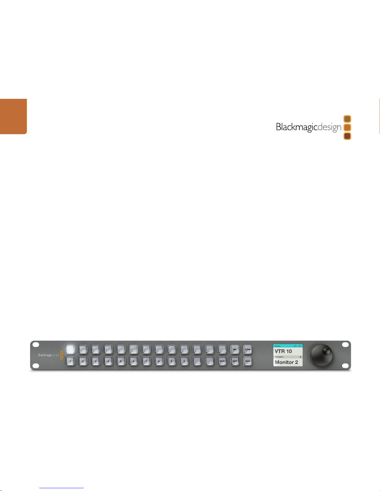
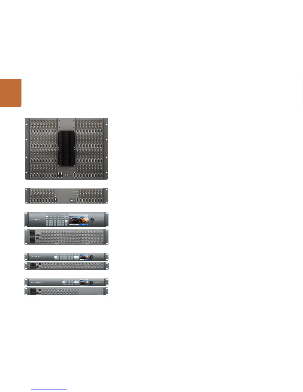
Broadcast Videohub
Studio Vid eohub
Smart Videohub 20x20
Smart Videohub 40x40
Smart Videohub 12x12
Smart Videohub 12x12
Page 6
6
Getting Started with Videohub Routers
Choosing a Videohub Router
Check this table for an overview of each Videohub's capabilities to help you decide which model you
will need. You can plan how to set it up so there are no nasty surprises. For example, it will tell you how
many connections your Videohub has, how much rack space will be required and which connec tion
options are available for controlling your Videohub.
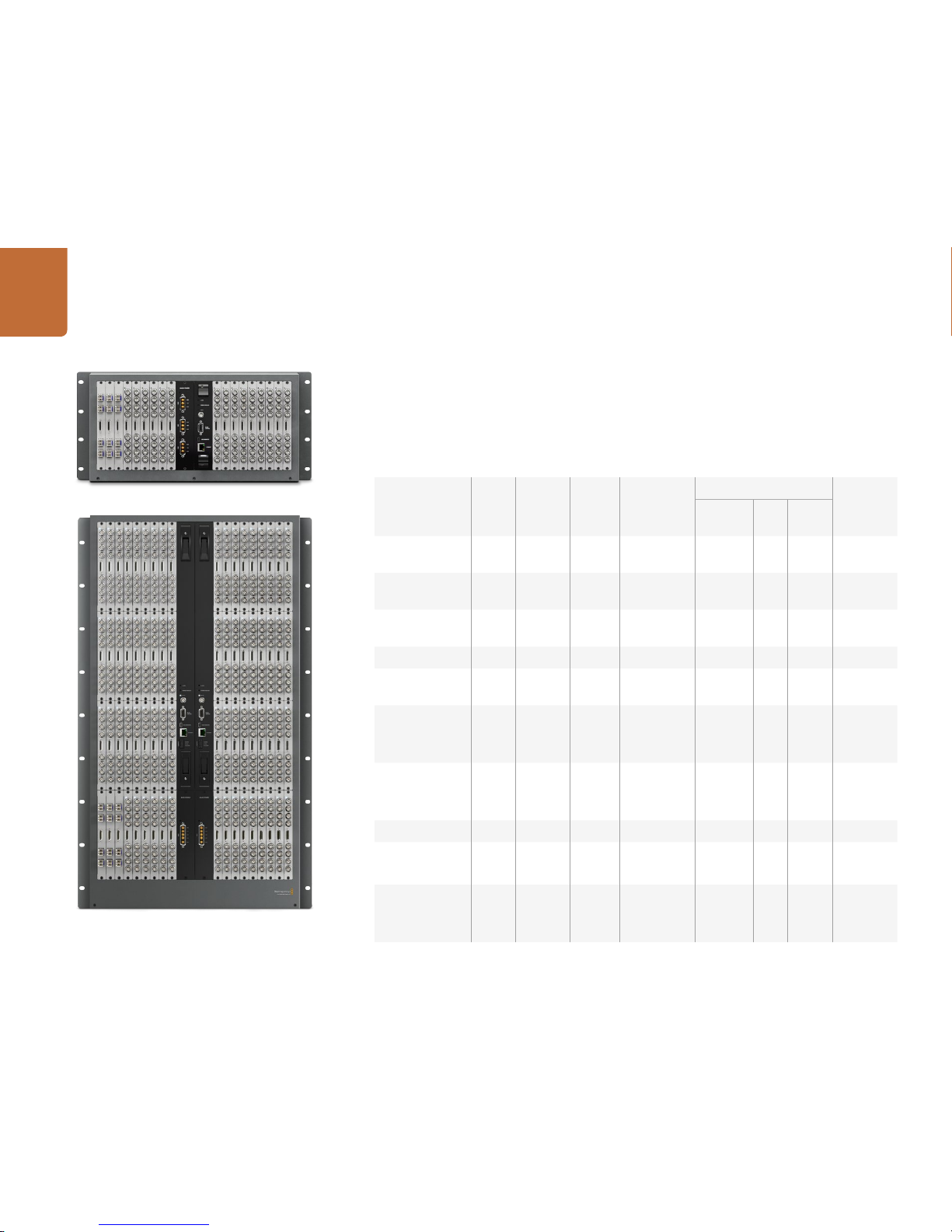
Universal Videohub 72
Universal Videohub 288
Videohub Router
SDI
Inputs
SDI
Outputs
Optical
IN/
OUT
RS-422 Deck
Control
Ports
Software Control
Maximum
Rack Units
Required
Ethernet USB
RS422
Universal
Videohub 288
288 288 √ 288 √ √ 25
Universal
Videohub 72
72 72 √ 72 √ √ 9
Broadcast
Videohub
72 144 72 √ 8
Studio Videohub 16 32 16 √ 2
Compact
Videohub
40 40 √ √ √ 2
Smart Videohub
40x40
Features pushbuttons
and LCD for lo cal control
40 40 √ √ 2
Smart Videohub
20x20
Features pushbuttons
and LCD for lo cal control
20 20 √ √ 1
Micro Videohub 16 16 √ √ √ 1
Smart Videohub
Features 32 pushbuttons
for loca l control
16 16 √ √ √ 1
Smart Videohub
12x12
Features push buttons
and LCD for lo cal control
12 12 √ √ 1
Page 7
7
Getting Started with Videohub Routers
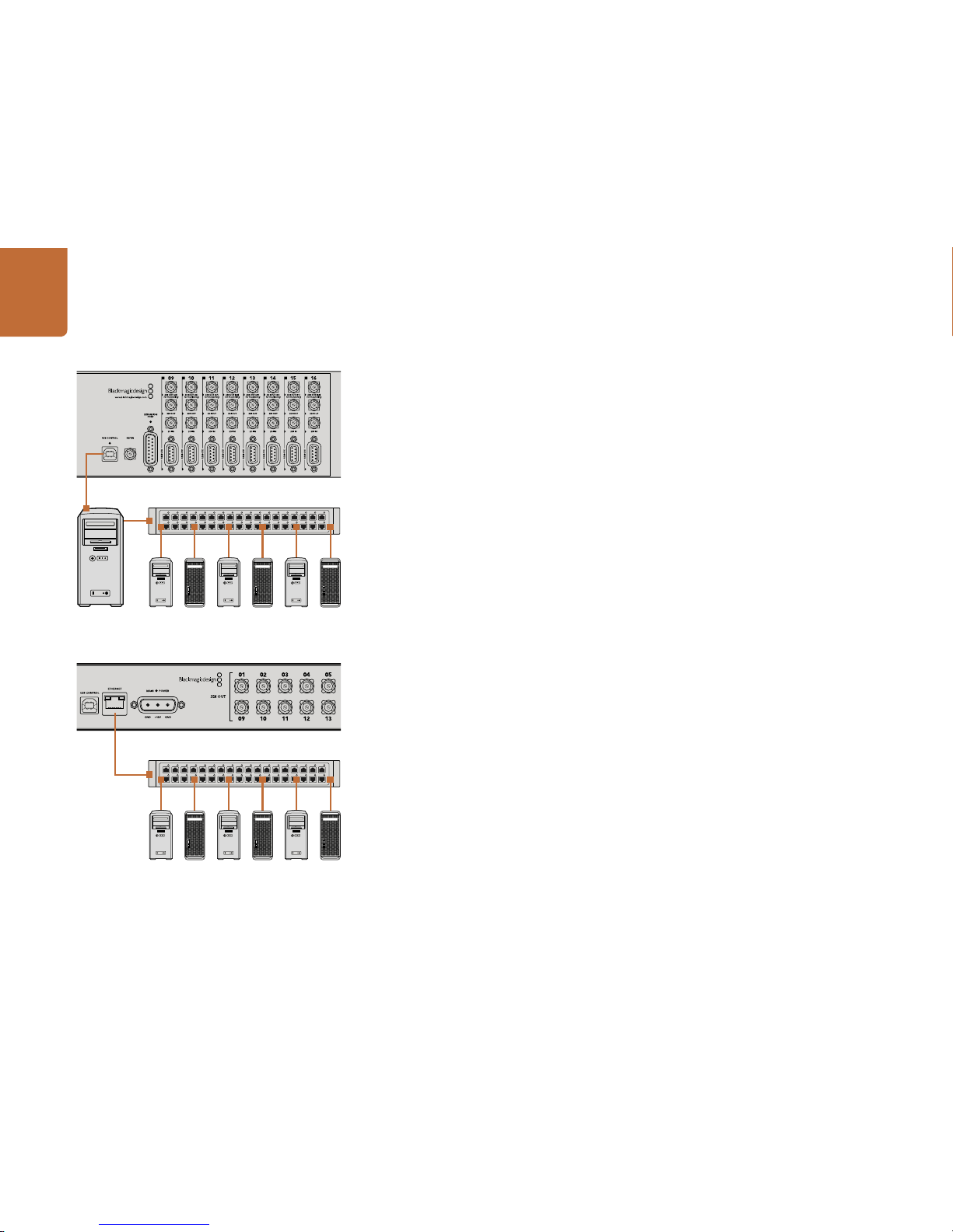
Connect to a Videohub Server with USB
All-in-one Videohubs can connect to any computer on your local area IP based network via USB. One
“server” computer on your network connects to Videohub via the plug and play USB connec tion, and
shares the Videohub with other computers and iPads on your network in a similar way to USB printer
sharing. You don’t need a dedicated or powerful computer for this task.
The Videohub Server can be any computer running Mac OS X, Windows and any number of Mac OS X
and Windows clients can connect to the server via USB.
To connect Videohub to the local area IP based network:
Step 1. Securely connect and power on all of the power supplies included with your Videohub.
Step 2. Connect the Videohub router to the Videohub Server computer with a s tandard USB 2.0 type
A-B male cable.
Step 3. Connec t the Videohub Server computer to your network switch. We strongly recommend
connecting the Videohub Server computer with reliable Ethernet cables in preference to
wireless networking. Wireless networking may be affected by interference from appliances
and other wireless devices.
Connect to an Ethernet Network
Many Videohub models have an Ethernet por t and can connect directly to your Ethernet network switch
and then to any computer on your local area IP based network. An integrated "Videohub Server" is
used when router control is performed via Ethernet. This means you don't need a separate computer
to act as the Videohub Server.
To connect Videohub to the local area IP based network:
Step 1. Securely connect and power on all of the power supplies included with your Videohub.
Step 2. Connect your Videohub router to the net work switch with a standard RJ45 Ethernet cable.
If you have a Universal Videohub 288 populated with two Crosspoint Cards, connec t Ethernet cables to
both for network failover redundancy. Your Universal Videohub 288 will have a single IP address, despite
having two Ethernet connections to the network switch.
Studio Vid eohub connecting to a ser ver via USB.
Micro Videohub connecting to an Ethernet Network.
Page 8
8
Getting Started with Videohub Routers
Plugging in Video
All SDI connections support auto detection of SD, HD or 3G-SDI, and reclocking on all SDI outputs.
Additionally, the Smar t Videohub 40x40, 20x20 and 12x12 also support 6G-SDI for Ultra HD video. All
Videohub mo dels feature regular-sized BNC ports which make it ea sy to connect to other SDI equipment
using regular SDI cables. If you're connecting Videohub to SDI equipment which has miniature SDI
connectors, such as DIN 1.0/2.3, we recommend using SDI cables which are terminated with a miniature
connector at one end and a regular BNC at the other.
Installing the Videohub Software
Videohub s oftware runs on th e latest Mountain Lion and Mavericks versio ns of Mac OS X. On the Windows
platform, the software runs on both 32 and 64-bit versions of Windows 7 and Windows 8.
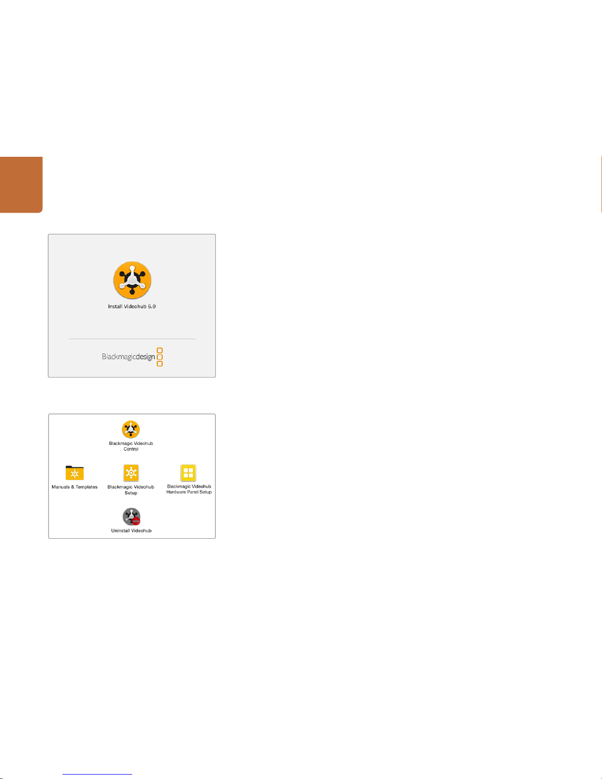
Mac OS X installation
Step 1: Double click the installer file from the supplied media or from your downloads folder if you
downloaded the software from the Blackmagic Design website.
Step 2: Follow the install prompts and Mac OS X will automatically install the software.
A folder called "Blackmagic Videohub" will be created within your Applications folder. The following
three applications are contained within the folder: Videohub Control, Videohub Setup and Videohub
Hardware Panel Setup.
Windows installation
Step 1. Double click the installer file from the supplied media or from your downloads folder if you
downloaded the software from the Blackmagic Design website.
Step 2. Follow the install prompts and accept the terms in the License Agreement and Windows will
automatically install the software.
Click the Windows Start button and then All Programs>Blackmagic Design>Videohub. The following
three applications are contained within the folder: Videohub Control, Videohub Setup and Videohub
Hardware Panel Setup.
Double click the ins taller and follow the prompts.
The Black magic Vid eohub folder cont ains the three
Videohub applications.
Page 9
9
Getting Started with Videohub Routers
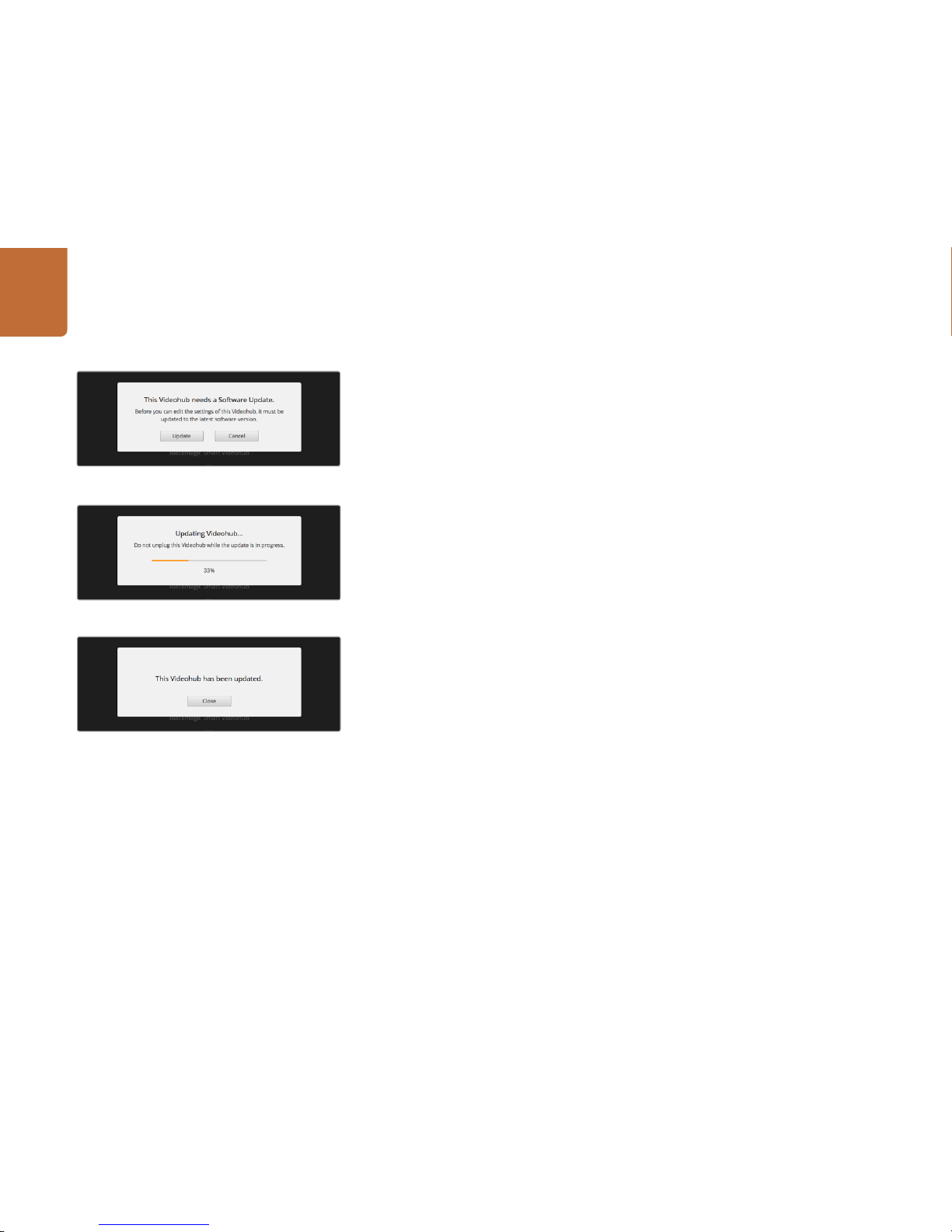
Updating your Videohub's Internal Software
Occasionall y, the internal soft ware in your Videohub will need to be updated. Updates to inter nal software
can provide new features, compatibility with new hardware and suppor t for new formats.
Please follow these steps to update your Videohub's internal software:
Step 1: Connect your computer to the Videohub's USB 2.0 connector.
Step 2: Launch Blackmagic Videohub Setup and it will automatically display any Videohubs that are
connected to your network.
Step 3: Select your Videohub by clicking on either the picture or the configuration icon.
Step 4: The utility will inform you if an update is required.
Step 5: If an update is required, click the Update button and allow the soft ware to install. Do not
unplug the Videohub while the update is in progress.
Step 6: Click the Close button when the update is finished.
Click the Update but ton to install the new internal software.
Click the Close but ton to finish the update.
Do not unplug the Videohub while the update is in progress.
Page 10
10
Getting Started with Videohub Routers
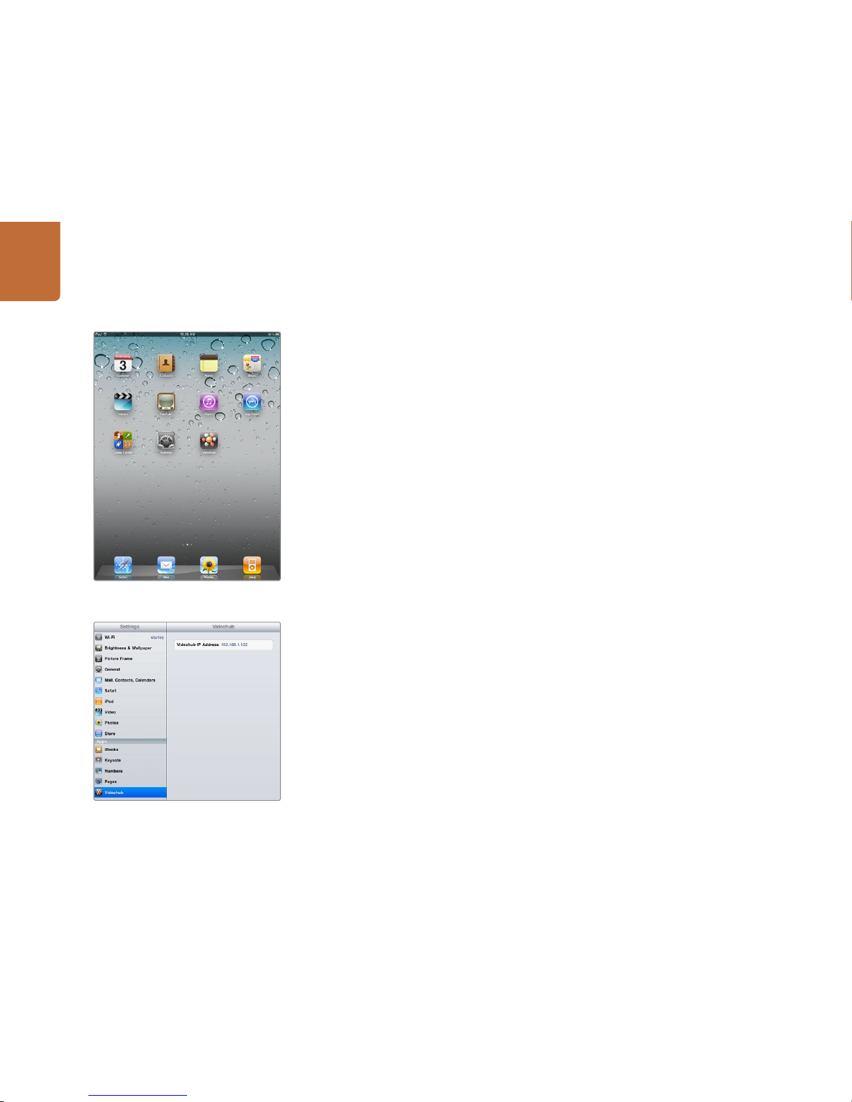
Installing the Videohub Software on iPad
The Videohub app for iPad can be downloaded using your iTunes Store account.
To download on your computer:
Step 1. Launch iTunes on your Mac OS X or Windows computer and click on iTunes Store button.
Step 2. Click in the Search Store field at the top-right of the window and enter "Videohub".
Step 3. Click on the Blackmagic Videohub iPad App to download the app to the iTunes library on
your computer.
Step 4. Connect your iPad and use iTunes to sync applications to it.
To download on your iPad:
Step 1. Tap the App Store icon.
Step 2. Tap the search field at the top of the screen and enter "Videohub".
Step 3. Click on the Free App button and then tap "Install App".
Download t he Videohub app to your iPad
Videohub settings on iPad
Page 11
11
Getting Started with Videohub Routers
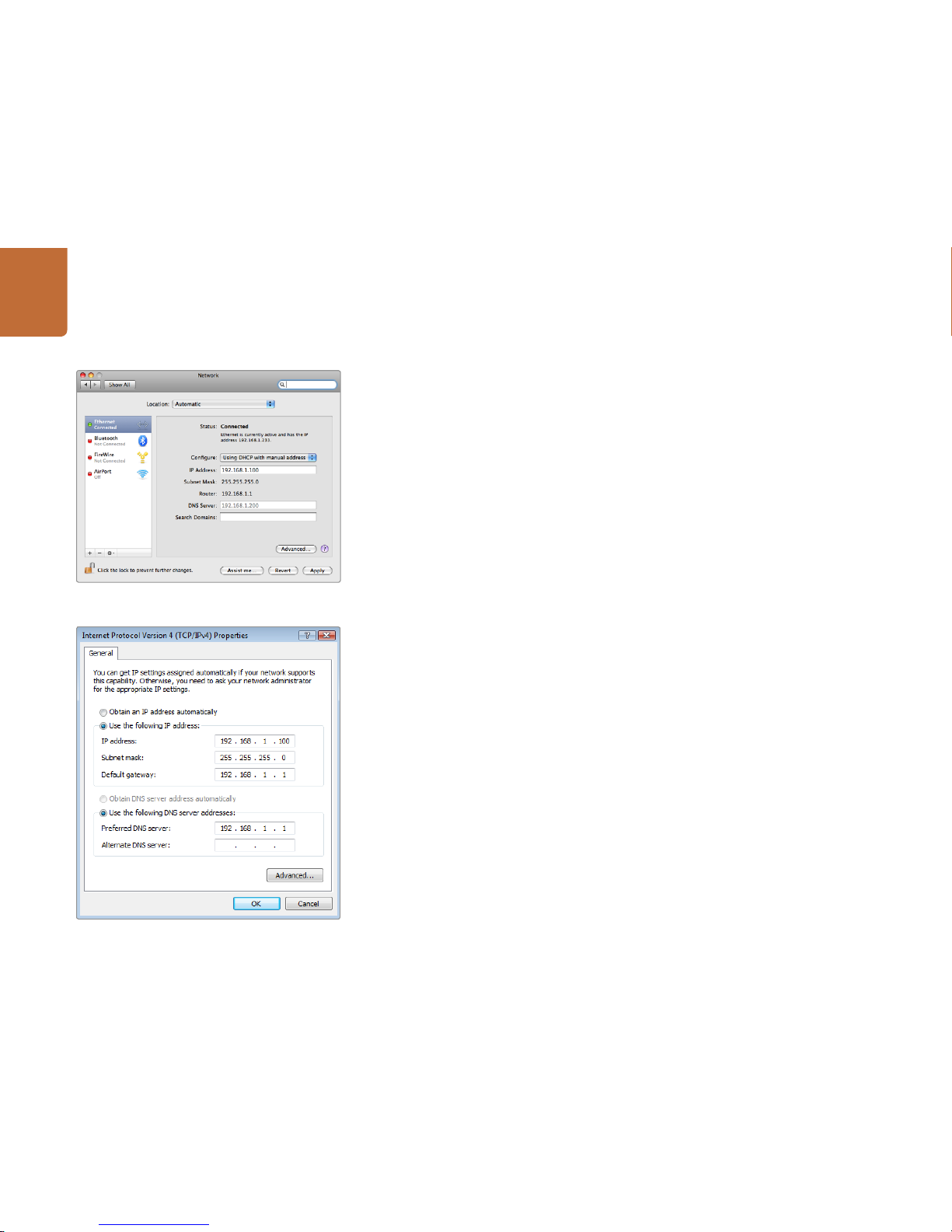
Network Preferences in Mac OS X set to “Using DHCP with
manual address” to provide a static IP address.
Network control panel in Windows set to “Use the following
IP addres s” to provide a static IP address.
Configuring your Videohub Server Settings
If you will be using Ethernet to connect to your Videohub, refer to the "Configuring Videohub with
Blackmagic Videohub Setup" section on the next page.
Videohubs without Ethernet are connected to a computer via USB and other control panels can see
the Videohub by looking for this computer. It effectively becomes a "server", that all the other control
panels on the network can connect to.
A Videohub "server" needs a static IP address and your network administrator will probably want to
configure this for you. Please follow the steps below for your respective operating system.
Mac OS X
Step 1. Go to System Preferences
Step 2. Click on Network
Step 3. Check the IP address in the configuration information for your Ethernet or Airport network.
Step 4. Set the network configuration to either Using DHCP with manual address or Manually.
Windows 7
Step 1. Open Control Panel
Step 2. Click on the Network and Sharing Center.
Step 3. Next to your connection, click Local Area Connection for Windows 7.
Step 4. Click on Proper ties and Select Internet Protocol Version 4 (TCP/IPv4).
Step 5. Click on Proper ties. Ensure "Use the following IP address" has been selected.
Windows 8
Step 1. From the desktop, hover over the right corner to bring up the charms bar.
Step 2. Click on Settings, then Control Panel.
Step 3. Click on the Network and Sharing Center.
Step 4. In the Network and Sharing Center, click on Chang e Adapter Settings on the lef t menu pane.
Step 5. Right click on your Ethernet connection and select Properties.
Step 6. Select Internet Protocol Version 4 (TCP/IPv4).
Ste p 7. Click the Properties button. Ensure "Use the following IP address" has been selected.
Page 12
12
Getting Started with Videohub Routers
Configuring Smart Videohub with the Control Panel
You can use the Smart Videohub's integrated control panel and LCD to configure network settings.
Your router will be visible to other computers and hardware panels and these devices can then
control the unit remotely and make the routing changes. If your router does not have a front panel
control, then you should use Blackmagic Videohub Setup to configure your network set tings.
Please follow these steps to set the IP address:
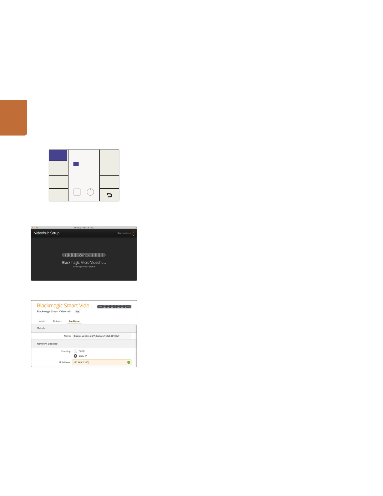
Step 1. Press the MENU button to enter the network configuration page.
Step 2. If not already selected, use the rotar y knob to select the "IP" tab.
Step 3. Press the TAKE button to highlight the first field and use the rotary knob to adjust this value.
Step 4. Repeat the process until you have set the desired IP address.
Step 5. Press the MENU button to exit the network configuration page.
If required, the Subnet and Gateway address can be set by the same method.
Configuring Videohub with Blackmagic Videohub Setup
Ethernet Videohub Server Settings
If your Videohub contains an integrated Videohub Server, you can use Blackmagic Videohub Setup to
set the IP address. Connec t the Videohub to your computer via USB and follow these steps:
Step 1. Launch Blackmagic Videohub Setup and it will automatically display any Videohubs that are
connected to your network.
Step 2. If you have multiple Videohubs you can use the left and right arrows to cycle through the
devices. If for any reason your Videohub does not appear, click on the Plus Sign and enter
your Videohub's IP address and then click Add.
Step 3. Select your Videohub by clicking on either the picture or the configuration icon.
Step 4. Click on the Configure tab and enable the Static IP button.
Step 5. Enter the IP address and if required, the Subnet Mask and Gateway address, and click Apply.
Step 6. Click the "Done" button to close the window.
If controlling Videohub via RS- 422, set the "Leitch protocol" switch to:
"Leitch Client" if the Videohub is to act as a client of a connected control panel and to listen
and respond to the control panel button presses.
"Leitch Server" if the Videohub is to be controlled from an automation system or third party
router control system.
The Vide ohub Server Configuration options will become act ive
when an Ethernet-equipp ed Videohub is connected via USB.
IP Address
IP
Gateway
DEST
Next Adjust
192.168.10.150
Subnet
Press the MENU button to enter the network page and use
the TAKE button and rotary kno b to set the IP address.
Blackmagic Videohub Setup.
Page 13
13
Getting Started with Videohub Routers
Blackmagic Videohub Setu p is also used to enter labels. The la bels are stored on the connec ted Videohub
and are also visible on the other control panels.
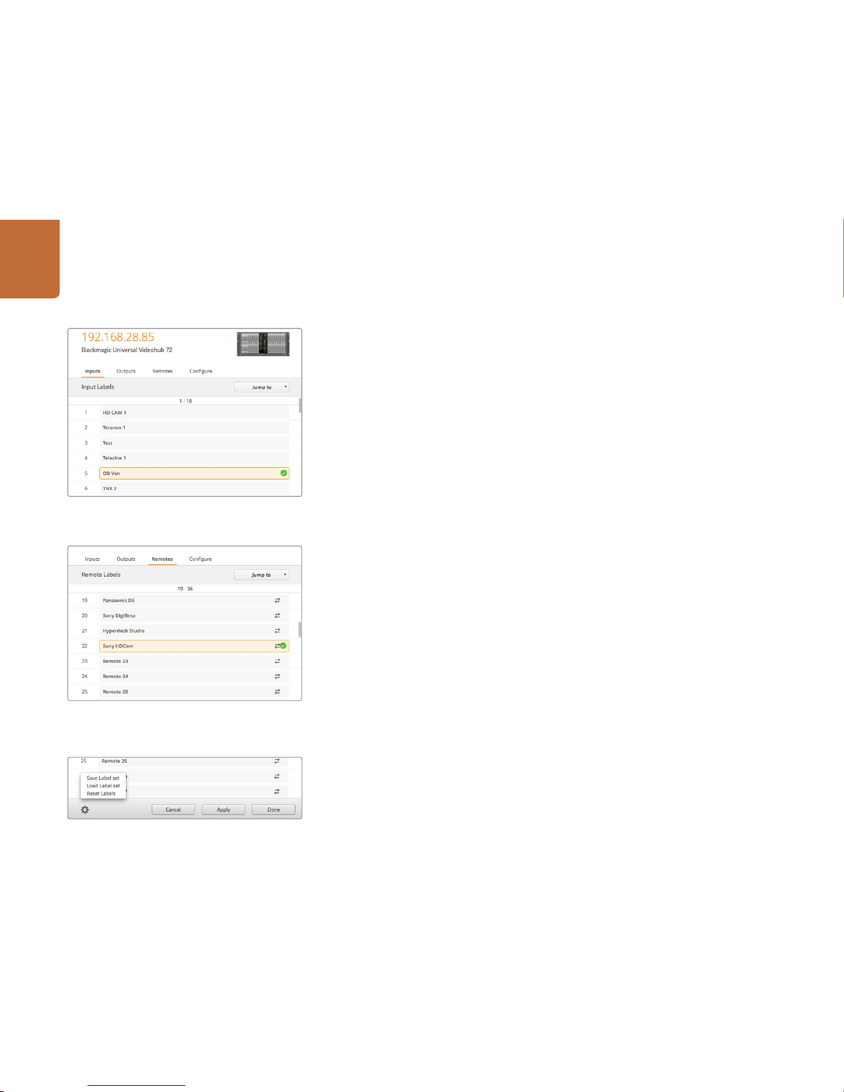
Customize Input Labels
Step 1. Click on the "Inputs" tab and then click on the first input that you wish to label.
Step 2. Enter label names for your inputs and click the "Apply" button to save the changes.
Step 3. Click the "Done" button to close the window.
For larger Videohubs, use the "Jump to" dropdown menu to quickly jump to a different range of inputs.
Customize Output Labels
Step 1. Click on the "Outputs" tab and then click on the first output that you wish to label.
Step 2. Enter label names for your outputs and click the "Apply" button to save the changes.
Step 3. Click the "Done" button to close the window.
Customize Remote Labels and Port Directions
Step 1. Click on the "Remotes" tab and then click on the first remote that you wish to label.
Step 2. Enter the label name and then click on the Port Direction icon and selec t from Auto, In or Out.
Step 3. Wh en you have finished labeling all your remotes click the "Apply" button to s ave the changes.
Step 4. Click the "Done" button to close the window.
Automatic port direction simplifies configuration and works well with most editing systems. However it
can take up to half a minute to automatically detect and apply a change in port direction. If you need
to make instant port direc tion changes, you can set the port direction manually.
For example, a capture card in a computer may be used to capture clips from in and out points on a
tape deck. The capture card should be configured as an "In" port so it can control decks. Users of AVID
Media Composer should also set the port direction manually to ensure reliable RS-422 communication.
Non-Roman character sets can be used with the Smart Videohub family.
Saving and Loading Labels
To save your labels, click on Settings (the gear icon) and selec t “Save Label set”. Choose a location to
store the file and click Save.
To load your labels, click on Settings and select “Load Label set”. Navigate to your previously saved
Label set file and click Load.
Customize Input Labels
Customize Remote Labels and Por t Directions
Saving and Loading La bels
Page 14
14
Getting Started with Videohub Routers
Introducing Blackmagic Videohub Control
Blackmagic Videohub Control provides a fast and intuitive way to view and switch between multiple
sources and destinations. Videohub Control is easy to use because it operates on a single video output
at a time. Selecting a destination (output) pushbutton shows which source (input) is connected to it by
illuminating the source pushbu tton. To change the source, simply click on a different s ource pushbutton.
It's that easy!
Selecting a Videohub
Launch Videohub Control and click on Settings (the gear icon) and choose "Select Videohub". Click on
the Videohub that you wish to control. If you completed the previous section on customizing labels, the
names you assigned will appear within the sof tware.
Adding Pushbuttons
Select the Setting s button and then selec t "Edit Buttons". Click on the Add button and choose whether
to add a source or destination pushbutton. The Set Button window appears and allows you to set the
SDI source or destination, RS-422 deck control and icon for the pushbutton. In most cases, deck control
is grouped with the associated SDI connections.
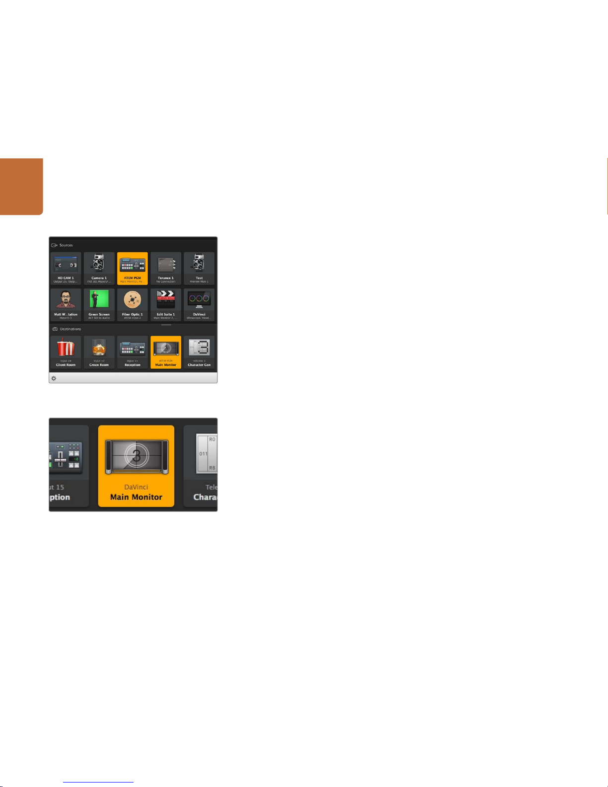
Viewing Routes
In order to see which video source has been routed to a video destination, such as a monitor, press the
button in the destinations panel to make the button illuminate. The associated video source button will
illuminate in the sources panel, making it immediately o bvious which source is conne cted to the monitor.
Switching Routes
In order to change the video source from a tape deck to a video camera, press a camera pushbutton
in the sources panel to immediately illuminate the camera pushbutton and route video to the video
monitor. The tape deck button is no longer illuminated and is disconnected from the video monitor.
See page 50 for more information on using Videohub Control.
This des tination is unlocked and is available to any Videohub
user on the network. The associated video source is
illuminated in the Sources panel and the source name
"DaVinci" i s displayed .
Videohub Control provides an intuitive, icon-driven
representation of the Videohub connections.
Page 15
15
Getting Started with Videohub Controllers
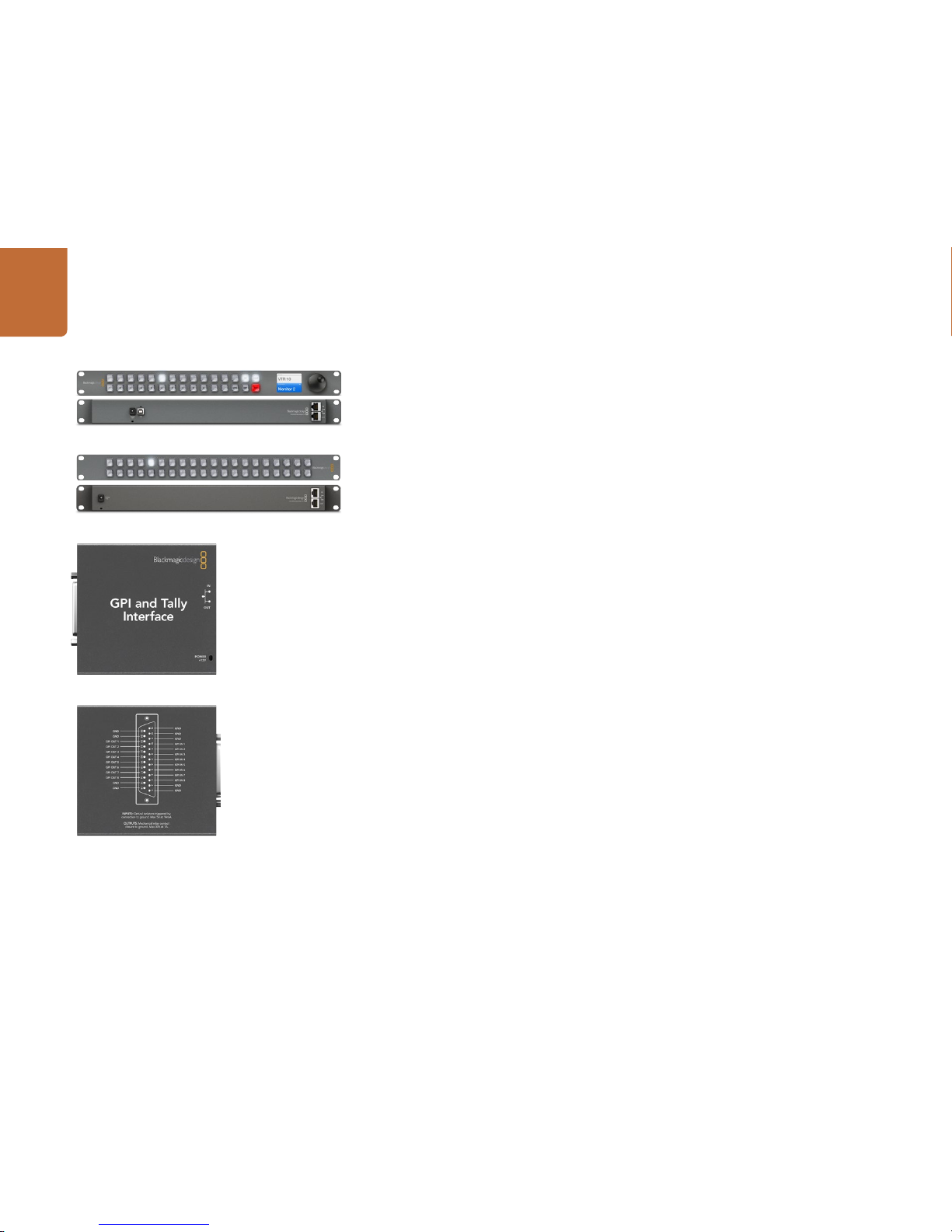
Introducing Videohub Controllers
Videohub Master Control
Videohub Master Control is a rack-mountable control panel with 30 backlit pushbuttons, LCD, scroll
wheel and Ethernet connectivity designed to perform Videohub crosspoint switching without using a
computer. Videohub Master Control can control all sources and destinations for any size of Videohub
router, as well as RS-422 deck control.
Videohub Ma ster Control uses por t labels to aid in fast selec tion of equipment using sof tware. 15 buttons
can be configured and labeled to provide fast selection of common equipment types, e.g., cameras,
decks and monitors. It also includes a loop through Ethernet por t for connec ting to additional control
panels, Videohub routers or other network devices.
Only 1 rack unit high and less than an inch thick, you can rack-mount Videohub Master Control at the
front or at the rear of the rack to leave space for other equipment.
Videohub Smart Control
Videohub Smart Control is a rack-mountable control panel with 40 backlit pushbuttons and Ethernet
connectivity, which works with all models of Videohub. It can be configured to work with one or many
SDI destination devices. Once configured for your SDI equipment and Vid eohub router, Videohub Smart
Control no longer requires a computer and can immediately change SDI routes as desired.
When configured for a single SDI destination, such as a monitor or deck, the pushbuttons can instantly
switch between 40 different SDI sources on the same Videohub router. When configured for multiple
SDI destinations, destination buttons become gold, source buttons become white and the lower right
button can be configured as a take button and illuminates red. Macro buttons illuminate green when
enabled and each one can be configured to perform up to 16 simultaneous crosspoint switches.
Only 1 rack unit high and less than an inch thick, you can rack-mount Videohub Smart Control at the
front or at the rear of the rack to leave space for other equipment. If you don’t have a rack, then you can
leave it in a safe place on the floor!
GPI and Tally Interface
GPI and Tally Interface is a low co st alternative for multi- camera productions where a Ca mera Control Unit
(CCU) operator needs to switch video from one of several cameras being controlled to a single monitor.
It features 8 configurable GPIs and 8 configurable GPOs. The GPIs send commands to your V ideohub by
ethernet to switch the selected camera to the operator's monitor under certain crosspoint conditions.
The GPOs send a tally signal to your cameras or other devices under certain crosspoint conditions.
Refer to the pinout diagram on the back of the unit when fabricating your custom cable.
Videohub Master Control
Videohub Smart Control
GPI and Tally Interface
Getting Started with Videohub Controllers
Pinout diag ram of the DB25 connec tor
Page 16
16
Getting Started with Videohub Controllers
Connecting USB to Configure the Control Panel
A USB 2.0 connection to a computer is u sed to configure the networ k settings of the Videohub Controller.
Be aware that the USB port of the Videohub Smar t Control is inaccessible once it is installed in a rack.
If you are likely to reconfigure Videohub Smart Control network settings periodically, then it may be
convenient to permanently connect a USB cable to the unit before installing Videohub Smart Control
in a rack.
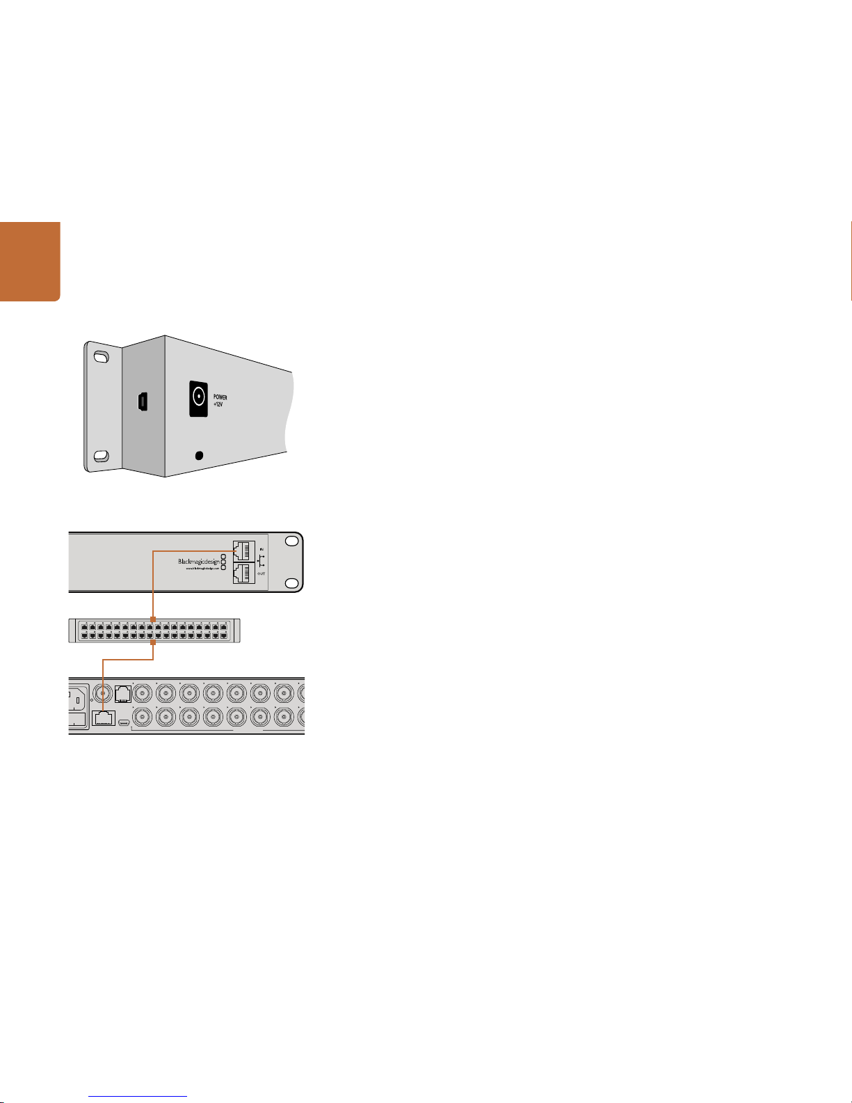
Plugging into an Ethernet Network
In most facilities, Videohub is usually shared via an Ethernet network switch so it can be controlled by
computers on the network as well as by Videohub control panels.
Videohub Master Control and Videohub Smart Control
Videohub Master Control and Videohub Smart Control connec t to any Videohub via standard Ethernet
networking and can be powered over Ethernet or with an external power supply.
If your Ethernet switch does not provide power over Ethernet, use the included universal power supply.
To connect a Videohub control panel to the local area IP based network:
Step 1. Connect the included power supply to your Videohub control panel. You can skip this step if
your networ k switch provides power over Ethernet. No problem will be caused by connec ting
the power supply and power over Ethernet at the same time.
Step 2. Use the network In por t on your Videohub control panel to connect to your network switch
with a standard RJ45 Ethernet cable.
Step 3. You might also wish to connect another network device to the network Out port on your
Videohub control panel, such as a Videohub router, another Videohub control panel or other
network devices such as a computer or VoIP phone. The Out port does not provide power
over Ethernet a nd any network device connected to thi s port will require its ow n power supply.
Side view of Videohub Smart Control showing the mini-B type
USB port.
13 16 19 SRC MENU
14 17 20 DEST VIDEO
15 18
1 4 7 10
2 5 8 11
3 6 9 12 CLEAR TAKE
SD/HD/3G/6G-SDI IN
SD/HD/3G/6G-SDI OUT
USB 2.0ETHERNET
REF IN
RS-422
CNTRL
1 3 5 7 9 11 13 15
17 19 1 3
2 4 6 8 10 12 14 16
18 20 2 4
5 7 9 11 13 15 17 19
6 8 10 12 14 16 18 20
Videohub Smart Control connected to a Smart Videohub
20x2 0 via an Ethernet Network Switch.
Page 17
17
Getting Started with Videohub Controllers
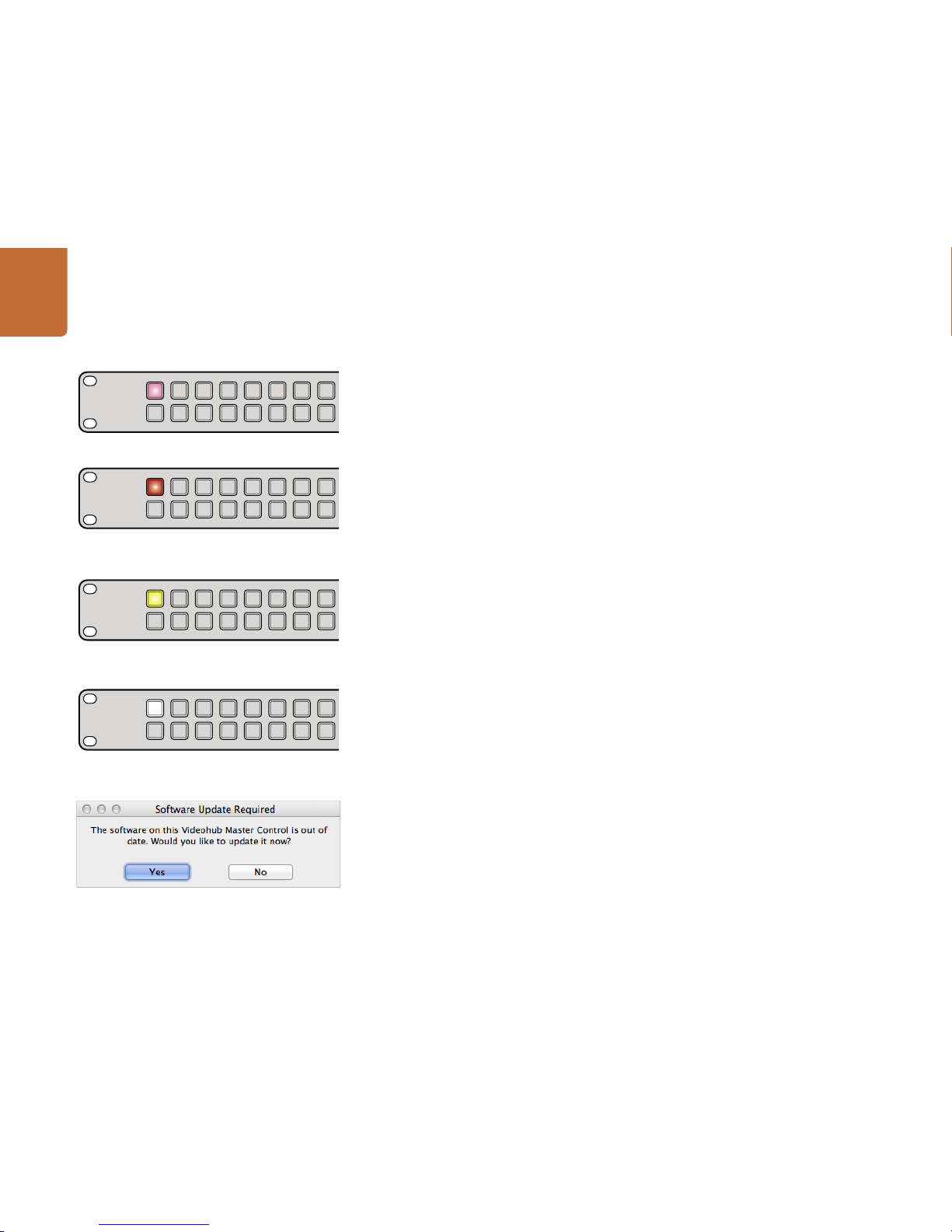
Control Panel Button Diagnostics
When power is first connected to a Videohub control panel, all the buttons will display their test lights
in the following sequence: red, green, blue and white. The top left button of a Videohub control panel
indicates its network status, using the following diagnostic display:
Pink flashing light - unit is attempting to acquire an IP address. The button should quickly become
red if the unit is set to use a static IP address, or if the unit successfully acquires an IP address from the
DHCP server.
Red flashing light - unit has acquired an IP address and is attempting to connec t to the Videohub Ser ver.
Make sure the Videohub Server computer is powered on and connected via Ethernet.
Yellow flashing light - unit has connected to a Videohub Ser ver computer but the Videohub Ser ver is
running an incompatible software or firmware version. Update Videohub with the latest version of the
Videohub software and firmware and then power cycle the Videohub control panel.
No flashing light - unit has successfully connec ted to the Videohub Ser ver and is ready to control the
Videohub if solid white, or solid white and gold, lights can be seen.
If the top left button took several minutes to turn red, the unit has failed to acquire an IP address and
has eventually provided itself with a self-assigned AutoIP address in the 169.254.xxx.xxx format. Unless
you wish to use an AutoIP address, disconnec t and firmly reconnect the network cables to ensure they
are properly connected, check for faulty network cables and make sure the DHCP server has spare IP
addresses available. Unplug and reconnect all power sources from the Videohub control panel so it will
request a new IP address from the DHCP server. The button should quickly become red. The unit will
only perform these diagnostics when it is not selected in Videohub Hardware Panel Setup software.
Updating the Software in your Videohub Controller
Follow these steps to check if your Videohub control panel's internal software is up to date:
Step 1. Connect your Videohub control panel to the computer via USB 2.0.
Step 2. Launch the Blackmagic Videohub Hardware Panel Setup.
Step 3. If a software update is required, the following message will appear: "Soft ware Update
Required. The sof tware on this Videohub Control is out of date. Would you like to update it
now?" Click Yes. The update will take about 2 minutes to complete.
Step 4. The message "Software Update Complete" should appear at completion of the update.
Click OK to dismiss the message. Settings can be changed now if desired and this is a good
opportunity to give each Videohub control panel a unique name.
Step 5. You can now unplug the USB cable from your Videohub control panel.
Videohub control panel is at tempting to acquire an IP addres s.
IP addres s has been acquired and control panel is
attempting to connect to the Videohub Server.
Videohub Server is running an incom patible software or
firmware version.
Control panel has successfully connected to the
Videohub Server.
This mes sage will appear if a i nternal software upda te is required.
Page 18
18
Getting Started with Videohub Controllers
Setting up your Videohub Controller
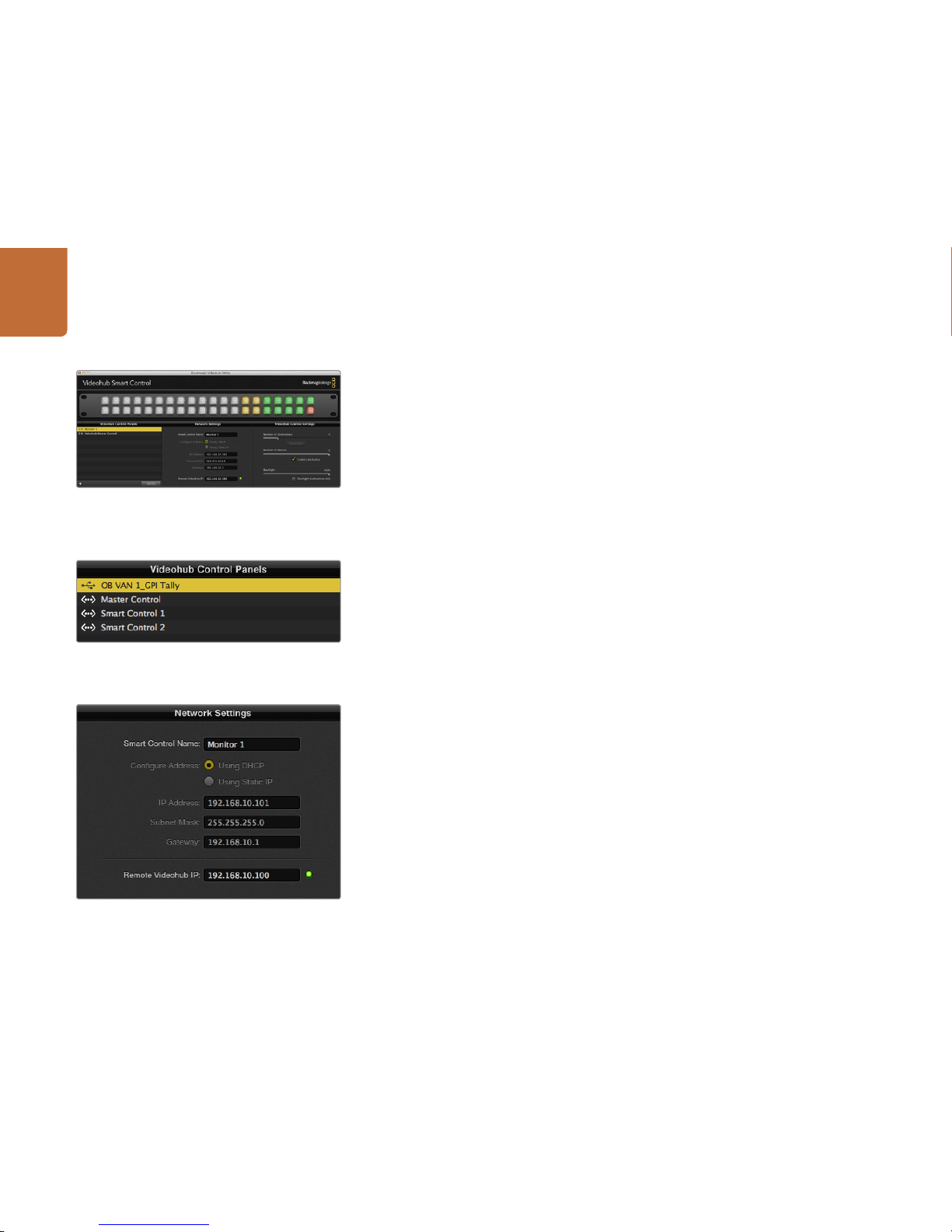
Configuring Videohub Hardware Panel Setup
When you launch Blackmagic V ideohub Hardware Panel Setu p, any Videohub control panels discovered
on the network will be listed in the Videohub Control Panels pane next to an Ethernet network icon. If
several Videohub control panels are listed, bu t you don't know which one is which, select one of them and
then press Identify. This will cause all the buttons of the selected Videohub control panel to flash white.
Select the desired Videohub control panel and you will be able to change it s name and control setting s.
Network settings will remain grayed out and can only be changed via USB.
If the desired Videohub control panel is not found on the network, the unit might not have received an
IP address via DHCP. To manually configure the unit with appropriate net work settings:
Step 1. Connect the Videohub control panel to your computer via a USB 2.0 cable.
Step 2. L aunch Blackmagic Videohub Hardware Panel Setup. If the utility prompt s you to update the
software, follow the prompts to complete the update.
Step 3. The USB-connec ted panel will be automatically selecte d in the Videohub Control Panels pane
and will display a USB icon next to its name. You can change all name, network and control
settings for the USB-connected unit. When you are finished, the USB cable can be removed.
If your Videohub control panel is selected in the control utility, the pushbuttons on the unit will light up
to match what is displayed in the software interface.
Network Settings
Each Videohub control panel requires an IP address to communicate with Videohub via your IP network .
When config uring a Videohub control pa nel via USB, you can choose DHCP or Static IP. DHCP automatically
obtains all the network settings for your Videohub control panel and is the easier choice.
If you decide to use a static IP address, please ask your system administrator for a spare IP address to
avoid creating a conf lict on your networ k. You will then need to complete the IP addre ss, subnet mask and
gateway details for your Videohub control panel. You must use a static IP address if you are connecting
directly to an Ethernet-equipped V ideohub, such as Compac t Videohub, without using a network s witch.
You will also need to complete the IP details for the remote Videohub that you wish to control with your
Videohub c ontrol panel. The remote Videohu b is the Videohub Ser ver. This could refer to a Video hub Server
computer or an integrated Videohub Ser ver onboard a Videohub model such as Univer sal Videohub 72.
The Black magic Vid eohub Hardware Panel Setup
automatically searches your network for any
Videohub control panels.
Any Ether net or USB connected control units will be listed in
the Videohub Control Panels pane with a corresponding icon.
Blackmagic Videohub Hardware Panel Setup network
settings
Page 19
19
Getting Started with Videohub Controllers
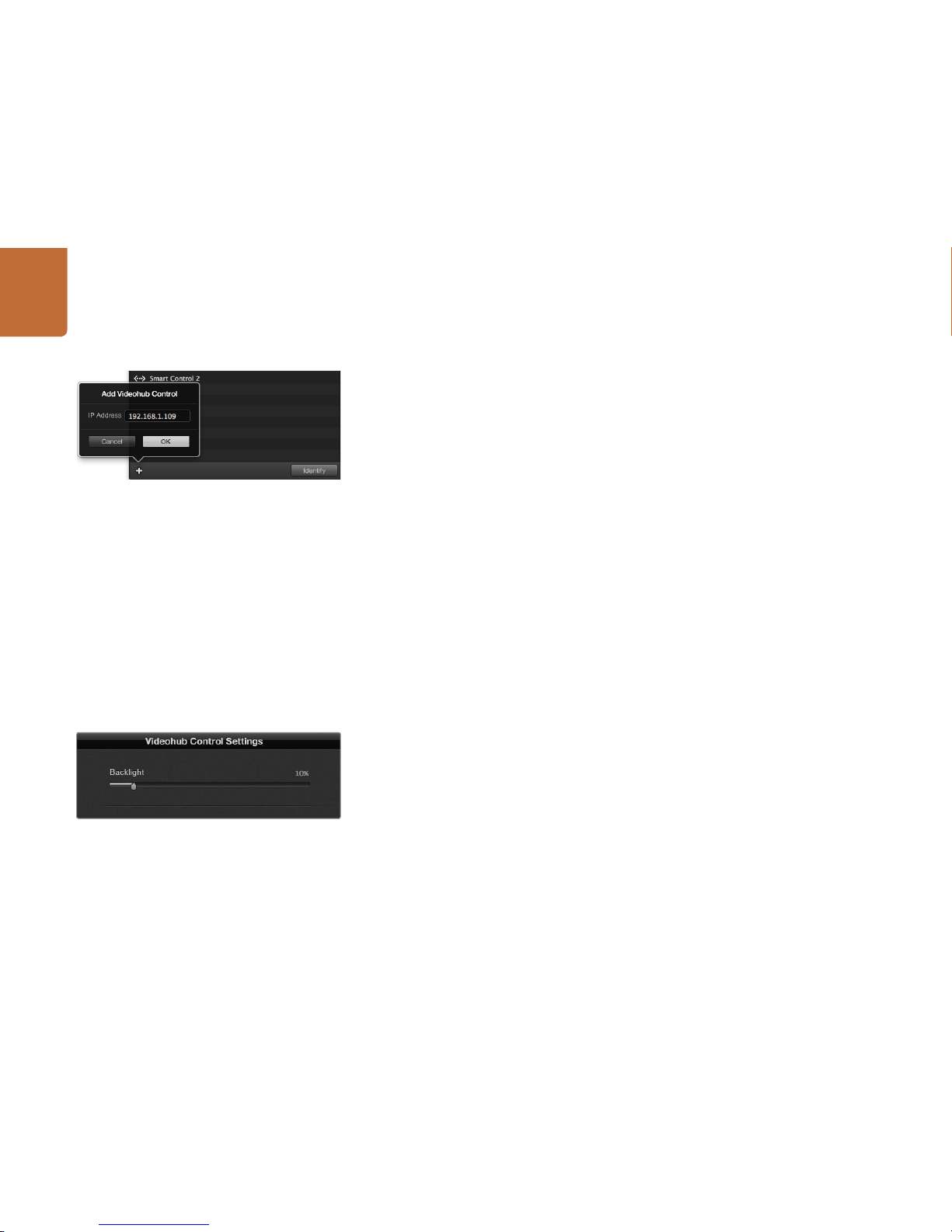
Add Videohub Control
If you already know the IP address of a Videohub control panel but it hasn't automatically appeared in
the Videohub Control Panels pane, you can add the unit manually.
Step 1. Press the + (add device) button at the bottom of the Videohub Control Panels pane.
Step 2. Type in the IP address of the Videohub Control Panel and press OK.
Step 3. The Videohub Control Panel will appear in the list with any other devices that are connected
to the Videohub.
If the Blackmagic Videohub Hardware Panel Setup does not find a Videohub control panel at the
specified address, you can use the Utility to manually add a Videohub control panel when connec ted
via Ethernet or USB.
Load/Save Settings
You can apply settings from an already configured Videohub control panel to other units.
Once you have set up your Videohub Control Panel's settings, choose File>Save Settings. This is useful
if you want to set up several units the same way, or keep a back up of your settings.
After loading pre-configured set tings on another control pan el, you only need to update network settings,
including the control panel name.
Configuring Videohub Master Control
Videohub Hardware Panel Setup software lets you customize the hardware features of each Videohub
control panel.
Backlight
Adjust the backlight slider as desired to vary the brightness of all backlit but tons.
Creating Button Labels
15 of the buttons can be labeled wit hin the control utility to provide fast selection of common equipment
types such as cameras, VTRs and monitors.
If you haven't done so already, you should standardize the port labels on your Videohub router before
labeling any buttons on your Videohub control unit.
Please refer to page 13 for detailed information on customizing your labels.
You can manually add a Videohub control panel, by IP
addres s, to the list of Videohub Control Panels.
You can adjust the brightness of all backlit buttons in
Videohub Master Control.
Page 20
20
Getting Started with Videohub Controllers
You are now ready to label the Videohub Master Control buttons.
Step 1. Launch the Videohub Hardware Panel Setup and select your Videohub Master Control from
the Panels pane.
Step 2. Click one of the 15 buttons in the picture of the panel. Enter a text la bel so it partially matches
the labels of SDI and deck control ports that you previously entered for your router.
Step 3. Click OK and continue labeling the other buttons as desired.
Step 4. You can immediately test the buttons as you program them and verif y the SDI routes are valid.
You can refer to page 23 for instructions on how to label the physical pushbuttons.
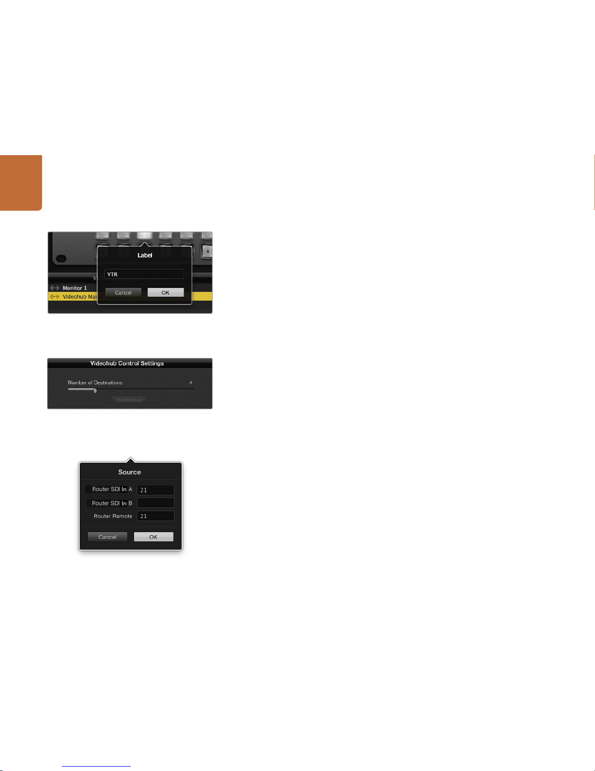
Configuring Videohub Smart Control
Videohub Hardware Panel Setu p lets you customize the hard ware features of each Videohu b control panel.
Number of Destinations
Videohub S mart Control can be configured as a Cu t-Bus controller o r as an XY controller. When configu red
as a Cut-Bus controller, every button represents an SDI source and there is only one destination.
When configured as an XY controller, Videohub Smart Control can work with up to 20 destinations.
The source buttons will illuminate white and the destination buttons will illuminate gold. Use this
configuration if you don’t intend to dedicate a Videohub Smart Control unit to each destination device.
Cut-Bus Configuration
Step 1. Drag the Number of Destinations slider to 1.
Step 2. Click on the Destination button. In the Router SDI Out A field, enter the number of the
Videohub output por t to which the destination device is conne cted. If your destination device
is receiving dual link HD-SDI or dual stream 3D, you will also need to enter an output port
number into the Router SDI Out B field. There is a Router Remote field if your Videohub is
also routing RS-422 deck control to the destination device.
Step 3. Click OK to confirm. All the buttons will become white, indicating that they are all sources.
Step 4. Click on each white button in the software interface to configure the source buttons.
Step 5. In the Router SDI In A field, enter the number of the Videohub input port to which the source
device is connected. If your destination device is receiving dual link HD-SDI or dual stream 3D,
you will also need to enter an input por t number into the Router SDI In B field. There is a Router
Remote field if your Videohub is also routing RS-422 deck control from the source device.
Step 6. Click OK to confirm.
Click on the desired button to edit its label.
Videohub Smart Control configured with multiple
destinations.
Enter the number of the V ideohu b port to which the SDI
device is connec ted.
Page 21
21
Getting Started with Videohub Controllers
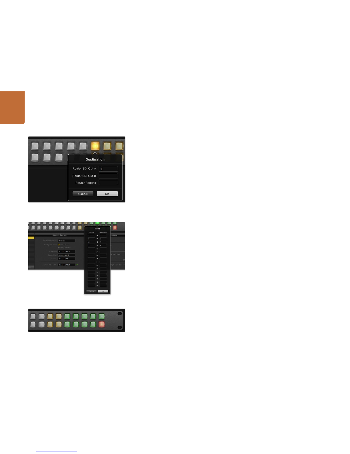
XY Controller Configuration
Step 1. Drag the Number of Destinations slider to the desired number.
Step 2. You can now configure the de stination buttons by clicking on each gold button in the sof tware
interface. In the Router SDI Out A field, enter the number of the Videohub output port to
which the destination device is connec ted. If your destination device is receiving dual link
HD-SDI or dual stream 3D, you will also need to enter an output port number in to the Router
SDI Out B field. There is also a Router Remote field if your Videohub is also routing RS-422
deck control to the destination device.
Step 3. Click OK to confirm. If you increase the number of destination bu ttons, there will be a matching
decrease in the number of available source buttons.
Step 4. Click on each white button in the software interface to configure the source buttons.
Step 5. In the Router SDI In A field, enter the number of the Videohub input port to which the source
device is connected. If your destination device is receiving dual link HD-SDI or dual stream 3D,
you will also need to enter an input por t number into the Router SDI In B field. There is also a
Router Remote field if yo ur Videohub is also routin g RS-422 deck contro l from the source device.
Step 6. Click OK to confirm.
Number of Macros
Macros allow you to make up to 16 cross point routing changes simult aneously with a single but ton press.
Step 1. Drag t he Number of Macros slider to enabl e up to 10 macro but tons. As you increase the num ber
of macro buttons, there will be a matching decrease in the number of available source buttons.
Step 2. Click a green macro button to reveal the corresponding Macro window and enter up to 16
pairs of sources and destinations.
Step 3. When finished, click OK to save the routes and close the window.
Take B utton
When the Enable Take Button checkbox is active, the lower right but ton on the control interface turns
red. Use this if you want a confirmation option to come up before your route change takes place. Press
the red take button to confirm your route change. The take button can be used with both Cut-Bus and
XY controller configurations and can also be used with macros.
Backlight
Adjust the backlight slider to vary the brightness of the backlit buttons as desired. Enable Backlight
Destinations Only if you wish to disable the backlighting of the white source buttons.
Click on the desired Destination but ton to configure it.
The Take button illuminates red in the lower right corner.
Up to 16 crosspoint routes can be changed by a single macro.
Page 22
22
Getting Started with Videohub Controllers
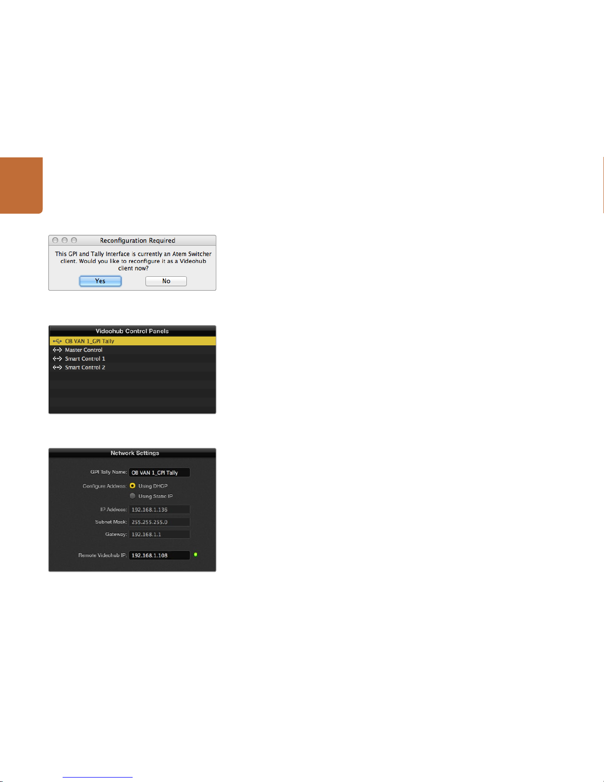
Setting up the GPI and Tally Interface
The GPI and Tally Interface is configured using the Videohub Hardware Panel Setup. Before you can use
the GPI and Tally Interface, you may need to install the latest version of the software.
Step 1. Connect the power adapter to the GPI and Tally Interface.
Step 2. Connec t the GPI and Tally Interface to your computer with a USB Type A to B cable.
Step 3. Open the soft ware and it will detect w hether your GPI and Tally Interface has been configured
for a Videohub before. If it has the sof tware will open wit hout any need for changes. Otherwise
a message will tell you your GPI and Tally Interface has been configured for use with an ATEM
Switcher and w ill need to be reconfig ured for use with Videohu b. Click Yes. After a few momen ts
the GPI and Tally Interface will be reconfigured as a Videohub client.
Configuring the GPI and Tally Interface
If your Videohub does not have an ethernet por t, or if it is only accessible over a network:
Step 1. Connect a USB type A to B cable from your GPI and Tally Interface to your computer.
Step 2. Connect an ethernet cable from the ethernet IN port on your GPI and Tally Interface to your
ethernet switcher.
Step 3. Open Videohub Hardware Panel Setup.
Step 4. You should see your GPI and Tally Interface with a USB icon next to it in the Videohub Control
Panels pane. Give your GPI and Tally Interface a unique name so it can be easily recognized.
To do so, click inside the GPI and Tally Name field and type a name.
Step 5. Check the option to configure your IP address either Using DHCP or a Static IP. Depending
on your setup, you may choose either so i t's probably a good idea to check with your network
administrator to see which is the better option.
Step 6. In the Remote Videohub IP field, enter the IP ad dress of the Videohub you want to connec t to.
A red light next to the field will turn green and the LED on the GPI and Tally interface will
illuminate when a connection has been established.
If you do not know the IP address of your Videohub:
Step 1. Connect the Videohub to your computer via USB.
Step 2. Launch the Videohub software and click on Videohub Server Preferences.
Step 3. Note down the IP address in the Remote Videohub IP address field.
You will need to reconfigure your GPI and Tally Interface to
work with Videohub.
GPI and Tally Interface connected v ia USB.
Enter a GPI and Tally Name and the IP address of the
Videohub you want to connec t to.
Page 23
23
Getting Started with Videohub Controllers
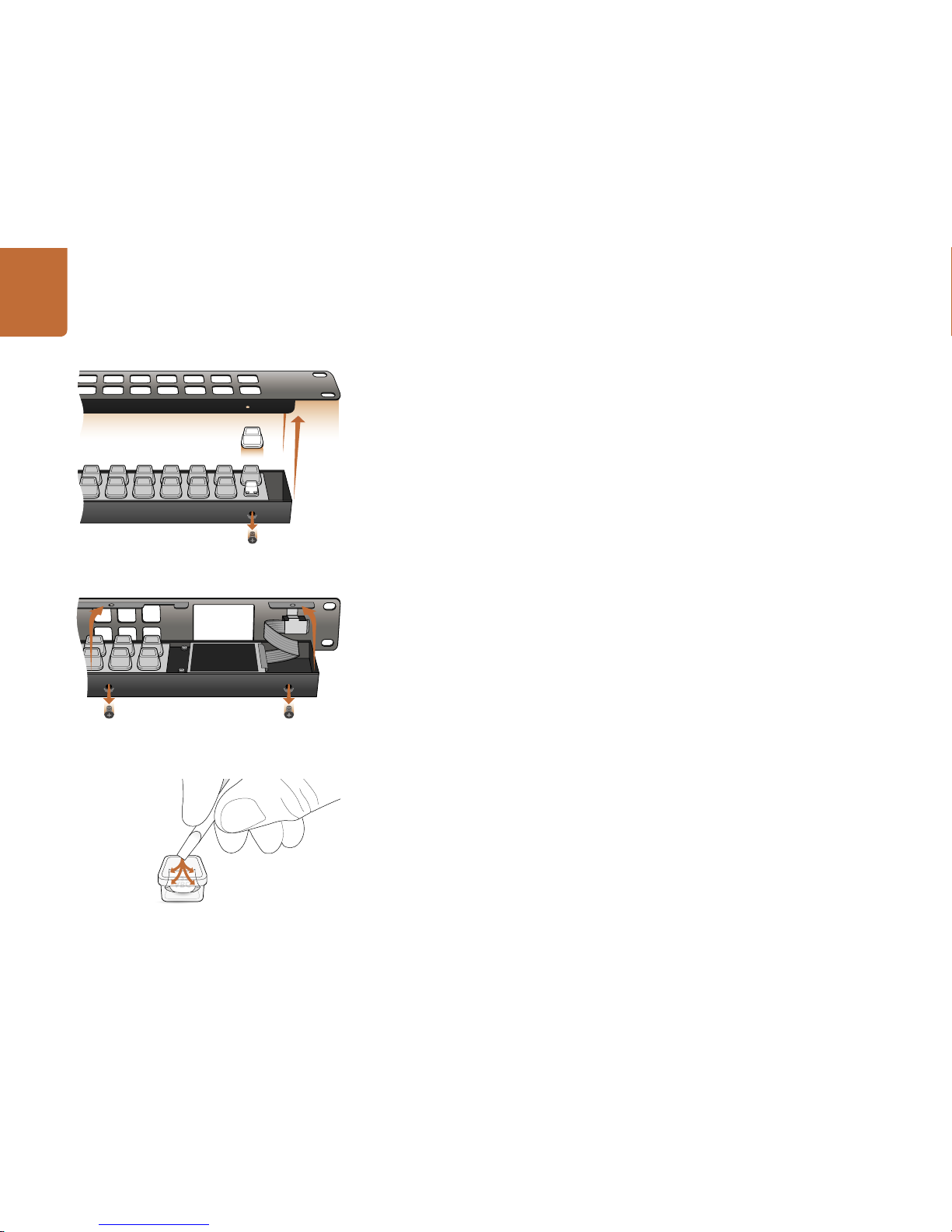
Labeling Pushbuttons
Videohub Master Control and Videohub Smart C ontrol have removable face plates, w hich provide access
to the pushbuttons for labeling.
Included with the software ins taller is a Videohub Control Labels folder containing both PDF and Adobe
Illustrator template files. You can print and use either of these files for labeling the but tons. The Illustrator
file contains tex t boxes so you can add your text la bels before printing them out. If you don’t have Adobe
Illustrator, you can just fill out and print the PDF file labels. Then cut out the square labels so they are
ready to be inser ted into the buttons.
To remove the face plate:
Step 1. Power off the unit, disconnect all cables and lay it flat with the buttons facing upwards.
Step 2. Using a No. 2 Phillips head screwdriver, remove the 8 screws found on the top and bottom
sides of the faceplate.
Step 3. Gently lift the face plate off the unit. If you have a Videohub Master Control, take care not to
pull on the data cable that connects the scroll wheel to the rest of the unit.
Step 4. The button caps can be easily lifted of f with your fingers. Remove t he clear cap from a button
that you wish to label, while taking care to avoid lifting the silicon button membrane.
Step 5. Loosely place the printed label into the upturned clear cap.
Step 6. Use a pointy device, such as the tip of a screwdriver, to lightly press the four corners of the
square paper label into the four rounded corners of the clear cap.
Ste p 7. Reinstate the clear cap containing the printed label. As the clear cap is pressed down onto
its silicon button, the paper label will be pushed forward, and neatly held flat against the
window of the clear cap. Repeat for as many buttons as you wish to label.
Step 8. Lower the face plate back into position, making sure the Blackmagic Design logo is the correct
way up. If you have a Video hub Master Control, make sure the da ta cable tucks neatl y into place.
St ep 9. Reinstate the eight screws.
Congratulations! Your Videohub control unit is now ready to use!
For Videohub Smart Control and Smart Videohub, remove the
8 screws, lift of f the face plate and then the but ton caps.
For Videohub Master Control, remove the 8 screws, lift off the
face plate and carefully allow the face plate to lie down next to
the rest of the unit. Then remove the button caps.
Lightly press the four corners of the square label into the
rounded corners of the clear cap.
Page 24
24
Using Videohub Routers
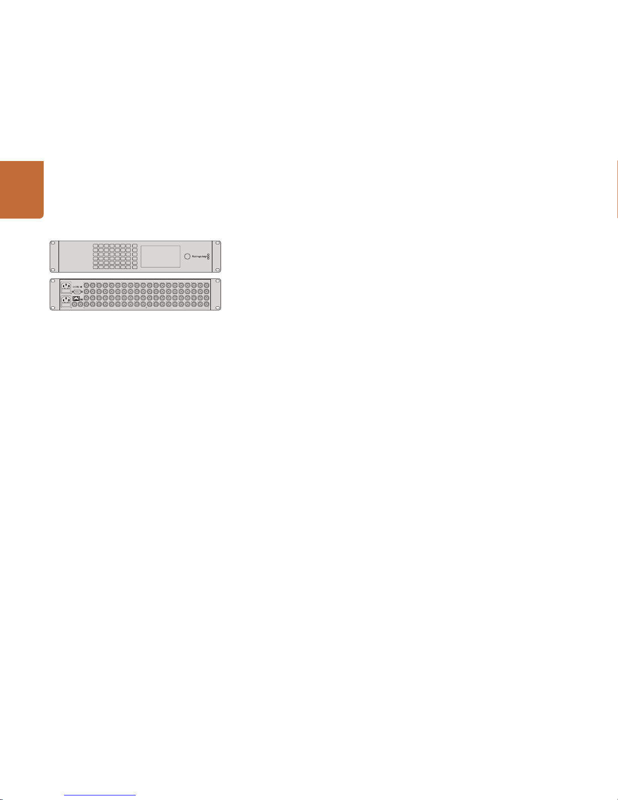
Smart Videohub 40x40
Smart Videohub 40x40 is a small router with a built in control panel and LCD and is perfect for locations
where minimal space is available, such as outside broadcast trucks. It features 40 SDI inputs, 40 SDI
outputs, reference input and output, a redundant universal power supply and powerful Videohub
routing control software.
All SDI connections support auto detection of SD, HD, 3G-SDI and 6G-SDI, and reclocking on all SDI
outputs. Simultaneous routing of Ultra HD, HD, SD video and DVB-ASI are suppor ted with Smart
Videohub 40x40.
Local router control is easy and intuitive using the built in control panel and LCD, and requires no
configuration and no computer. The LCD allows you preview source and destination video without an
external monitor.
Remote router control can also be performed via 10/100Base-T Ethernet or serial connections. If router
control is per formed via Ethernet, the integrated “Videohub Ser ver” is used and you need only provide
an Ethernet cable to connect Smart Videohub 40x40 to your Ethernet network switch.
Third part y router controllers can control Smart Videohub 40x40 via Ethernet, or as an RS-422 slave
device, for router crosspoint switching.
Occasionally, the internal soft ware of the Smart Videohub 40x40 will need to be updated. Blackmagic
Videohub Setup will prompt you if an update is required. The utility uses the USB 2.0 connection and
you will need to provide a USB 2.0 type A Male to Mini B cable.
Smart Videohub 40x40 is 2 rack units high and features a shallow form factor. You will need to leave
enough space in your equipment r ack to install the Smart V ideohub hardware. You can rack-mount Smar t
Videohub 40x40 at the front or at the rear of the rack to leave space for other equipment.
Smart Videohub 40x40 includes a redundant universal power supply for use in all countries. To use
redundancy you will need to provide two standard IEC cords with C13 connectors and two mains power
sockets. A third power socket will be required if you decide to use a dedicated ser ver computer.
Turn the page for instr uctions on how to make route chang es with the control panel an d LCD. Alternatively,
if you need to learn how to integrate your router into an existing network, turn to page 7.
SRC
MENU
DEST
VIDEO
1
2
3
4
5
6
7
8
9
10
11
12
13
14
15
16
17
18
19
20
21
22
23
24
25
26
27
28
29
30
31
32
33
34
35
36
37
38
39
40
CLEAR
TAKE
Smart Videohub 40 x 40
SRC
MENU
DEST
VIDEO
1
2
3
4
5
6
7
8
9
10
11
12
13
14
15
16
17
18
19
20
21
22
23
24
25
26
27
28
29
30
31
32
33
34
35
36
37
38
39
40
CLEAR
TAKE
REF IN
ETHERNET
RS-422
CNTRL
REF OUT
USB
SD/HD/3G/6G-SDI OUTSD/HD/3G/6G-SDI IN
Smart Videohub 40 x 40
1
2
3
4
5
6
7
8
9
10
11
12
13
14
15
16
17
18
19
20
21
22
23
24
25
26
27
28
29
30
31
32
33
34
35
36
37
38
39
40
1
2
3
4
5
6
7
8
9
10
11
12
13
14
15
16
17
18
19
20
21
22
23
24
25
26
27
28
29
30
31
32
33
34
35
36
37
38
39
40
Using Videohub Routers
Page 25
25
Using Videohub Routers
SRC
MENU
DEST
VIDEO
19
20
21
22
23
24
25
26
27
28
29
30
31
32
33
34
35
36
37
38
39
40
CLEAR
TAKE
SRC
MENU
DEST
VIDEO
1
2
3
4
5
6
7
8
9
10
11
12
13
14
15
16
17
18
19
20
21
22
23
24
25
26
27
28
29
30
31
32
33
34
35
36
37
38
39
40
CLEAR
TAKE
40 x 40
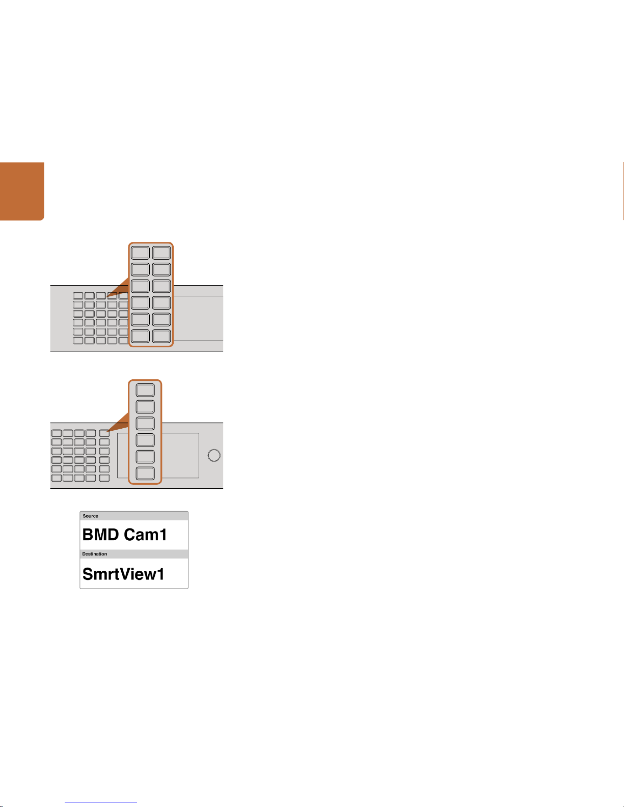
Using the Smart Videohub 40x40 Control Panel and LCD
Smart Videohub 40x40 features a built in control panel and LCD. Routing changes can be made without
needing a computer by simply using the numbe red pushbuttons. Remote ro uter control can also be use d.
Menu Buttons Explained
MENU
Switches bet ween the routing display and the network configuration page.
VIDEO
Use this button in conjunc tion with the SRC and DEST buttons to display either the Source or Destination
video on the LCD.
SRC
Press this button and then a numbered pushbutton to select your Source.
DEST
Press this button and then a numbered pushbutton to select your Destination.
CLEAR
Press this button to discard a route change.
TAK E
Press this button to confirm a route change.
Changing Routes
Step 1. Select the DEST button and then a numbered pushbutton. Alternatively, you can use the
rotary knob to scroll through the Destination numbers. The lower half of the LCD displays the
Destination and will change accordingly. If you have already customized your labels, the d evice
name eg: "SmartView1" will be displayed.
Step 2. Select the SRC button and then a numbered pushbutton. Alternatively, you can use the rotary
knob to scroll through the Source numbers. Th e numbers will scroll in alphabe tical order and not
the numerical order. The top half of the LCD displays the Sources and will change accordingly.
If you have already customized your labels, the device name will be displayed. The CLEAR
button will flash white and the TAKE button will flash red. Press the TAKE button to confirm
the route change. Or, you can press the CLEAR button to discard the route change.
The pushbuttons override any existing routes, including destinations locked with Videohub software.
The numbered push buttons corre spond to either the SDI
inputs (sources) or SDI outputs (des tinations).
Menu but tons allow for simple and quick route change s.
SRC
MENU
DEST
VIDEO
CLEAR
TAKE
SRC
MENU
DEST
VIDEO
13
14
15
16
17
18
19
20
21
22
23
24
25
26
27
28
29
30
31
32
33
34
35
36
37
38
39
40
CLEAR
TAKE
The LCD provides inst ant feedback of route selec tions and
changes and allows you preview source and destination
video without an ex ternal monitor.
Page 26

26
Using Videohub Routers
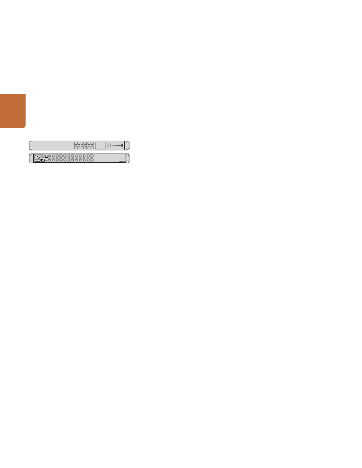
Smart Videohub 20x20
Smart Videohub 20x20 is a tiny router with a built in control panel and LCD and is perfect for locations
where minimal space is available, such as outside broadcast trucks. It features 20 SDI inputs, 20 SDI
outputs, reference input, a universal power supply and powerful Videohub routing control software.
All SDI connec tions support au to detection of SD, HD, 3G-SDI and 6G-SDI, and recl ocking on all SDI inputs.
Simultaneou s routing of Ultra HD, HD, SD video and DVB-ASI are sup ported with Smar t Videohub 20x2 0.
Local router control is easy and intuitive using the built in control panel and LCD, and requires no
configuration and no computer. The LCD allows you preview source and destination video without an
external monitor.
Remote router control can also be performed via 10/100Base-T Ethernet or serial connections. If router
control is per formed via Ethernet, the integrated “Videohub Ser ver” is used and you need only provide
an Ethernet cable to connect Smart Videohub 20x20 to your Ethernet network switch.
Third part y router controllers can control Smart Videohub 20x20 via Ethernet, or as an RS-422 slave
device, for router crosspoint switching.
Occasionally, the internal soft ware of the Smart Videohub 20x20 will need to be updated. Videohub
Setup will prompt you if an update is required. The utility uses the USB 2.0 connection and you will need
to provide a USB 2.0 type A Male to Mini B cable.
Smart Videohub 20x20 is 1 rack unit high and features a shallow form factor. You will need to leave
enough space in your equipment r ack to install the Smart V ideohub hardware. You can rack-mount Smar t
Videohub 20x20 at the front or at the rear of the rack to leave space for other equipment.
Smart Videohub 20 x20 includes a universal power supply for use in all countries. You will need to provide
a standard IEC cord with a C13 connector and a mains power socket. A second power socket will be
required if you decide to use a dedicated ser ver computer.
Turn the page for instr uctions on how to make route chang es with the control panel an d LCD. Alternatively,
if you need to learn how to integrate your router into an existing network, turn to page 7.
13 16 19 SRC MENU
14 17 20 DEST VIDEO
15 18
1 4 7 10
2 5 8 11
3 6 9 12 CLEAR TAKE
SD/HD/3G/6G-SDI IN SD/HD/3G/6G-SDI OUT
USB 2.0ETHERNET
REF IN
RS-422
CNTRL
1 3 5 7 9 11 13 15 17 19 1 3
2 4 6 8 10 12 14 16 18 20 2 4
5 7 9 11 13 15 17 19
6 8 10 12 14 16 18 20
Smart Videohub 20 x 20
Page 27

27
Using Videohub Routers
13 16 19 SRC MENU
14 17 20 DEST VIDEO
15 18
10
11
12 CLEAR TAKE
Using the Smart Videohub 20x20 Control Panel and LCD
Smart Videohub 20x20 features a built in control panel and LCD. Routing changes can be made without
needing a computer by simply using the numbe red pushbuttons. Remote ro uter control can also be use d.
Menu Buttons Explained
SRC
Press this button and then a numbered pushbutton to select your Source.
DEST
Press this button and then a numbered pushbutton to select your Destination.
CLEAR
Press this button to discard a route change.
MENU
Toggles between the routing display and the network configuration page.
VIDEO
Use this but ton in conjunction wit h the SRC and DEST buttons to di splay either the Source or Des tination
video on the LCD.
TAK E
Press this button to confirm a route change.
Changing Routes
Step 1. Select the DEST button and then a numbered pushbutton. Alternatively, you can use the
rotary knob to scroll through the Destination numbers. The lower half of the LCD displays
the Destination and will change accordingly. If you have already customized your labels, the
device name eg: "SmartView1" will be displayed.
Step 2. Select the SRC button and then a numbered pu shbutton. Alternatively, you can use the rotary
knob to scroll through the Source numbers. The numbers will scroll in alphabetical order
and not the numerical order. The top half of the LCD displays the Sources and will change
accordingly. If you have already customized your labels, the device name will be displayed.
The CLEAR button will flash white and the TAKE button will flash red. Press the TAKE button
to confirm the route change. Or, you can pres s the CLEAR button to discard the rou te change.
The pushbuttons override any existing routes, including destinations locked with Videohub software.
The numbered push buttons corre spond to either the SDI
inputs (sources) or SDI outputs (des tinations).
Menu but tons allow for simple and quick route change s.
19 SRC MENU
20 DEST VIDEO
CLEAR TAKE
13 16 19 SRC MENU
14 17 20 DEST VIDEO
15 18
The LCD provides inst ant feedback of route selec tions and
changes and allows you preview source and destination
video without an ex ternal monitor.
Page 28
28
Using Videohub Routers
Smart Videohub 12x12
Smart Videohub 12x12 is a tiny router with a built in control panel and LCD and is perfec t for locations
where minimal space is available, such as outside broadcast trucks. It features 12 SDI inputs, 12 SDI
outputs, reference input, a universal power supply and powerful Videohub routing control software.
All SDI connec tions support au to detection of SD, HD, 3G-SDI and 6G-SDI, and recl ocking on all SDI inputs.
Simultaneou s routing of Ultra HD, HD, SD video and DVB-ASI are supported with Smar t Videohub 12x12.
Local router control is easy and intuitive using the built in control panel and LCD, and requires no
configuration and no computer. The LCD allows you preview source and destination video without an
external monitor.
Remote router control can also be performed via 10/100Base-T Ethernet or serial connections. If router
control is per formed via Ethernet, the integrated “Videohub Ser ver” is used and you need only provide
an Ethernet cable to connect Smart Videohub 12x12 to your Ethernet network switch.
Third part y router controllers can control Smart Videohub via Ethernet, or as an RS-422 slave device, for
router crosspoint switching.
Occasionally, the internal soft ware of the Smart Videohub 12x12 will need to be updated. Videohub
Setup will prompt you if an update is required. The utility uses the USB 2.0 connection and you will need
to provide a USB 2.0 type A Male to Mini B cable.
Smart Videohub 12x12 is 1 rack unit high and features a shallow form factor. You will need to leave
enough space in your equipment r ack to install the Smart V ideohub hardware. You can rack-mount Smar t
Videohub at the front or at the rear of the rack to leave space for other equipment.
Smart Videohub 12x12 includes a universal power supply for use in all countries. You will need to provide
a standard IEC cord with a C13 connector and a mains power socket. A second power socket will be
required if you decide to use a dedicated ser ver computer.
Turn the page for instr uctions on how to make route chang es with the control panel an d LCD. Alternatively,
if you need to learn how to integrate your router into an existing network, turn to page 7.
1 4 7 10 SRC MENU
2 5 8 11 DEST VIDEO
3 6 9 12 CLEAR TAKE
SD/HD/3G/6G-SDI IN SD/HD/3G/6G-SDI OUT
USB 2.0ETHERNET
REF IN
RS-422
CNTRL
1 3 5 7 9 11 1 3 5 7 9 11
2 4 6 8 10 12 2 4 6 8 10 12
Smart Videohub 12 x 12
Page 29

29
Using Videohub Routers
Using the Smart Videohub 12x12 Control Panel and LCD
Smart Videohub 12x12 features a built in control panel and LCD. Routing changes can be made without
needing a computer by simply using the numbe red pushbuttons. Remote ro uter control can also be use d.
Menu Buttons Explained
SRC
Press the SRC but ton and then a numbered pushbutton to select your Source.
DEST
Press the DEST button and then a numbered pushbut ton to selec t your Destination.
CLEAR
Press the CLEAR button to discard a route change.
MENU
Press the MENU button to toggle between the routing display and the network configuration page.
VIDEO
Press the VIDEO button and then either the SRC or DEST buttons to display the video on the LCD.
TAK E
Press this button to confirm a route change.
Switching Routes
Step 1. Select the DEST button and then a numbered pushbutton. Alternatively, you can use the
rotary knob to scroll through the Destination numbers. The lower half of the LCD displays
the Destination and will change accordingly. If you have already customized your labels, the
device name eg: "SmartView1" will be displayed.
Step 2. Select the SRC button and then a numbered pu shbutton. Alternatively, you can use the rotary
knob to scroll through the Source numbers. The numbers will scroll in alphabetical order
and not the numerical order. The top half of the LCD displays the Sources and will change
accordingly. If you have already customized your labels, the device name will be displayed.
The CLEAR button will flash white and the TAKE button will flash red. Press the TAKE button
to confirm the route change. Or, you can pres s the CLEAR button to discard the rou te change.
The pushbuttons override any existing routes, including destinations locked with Videohub software.
1 4 7 10 SRC MENU
2 5 8 11 DEST VIDEO
3 6 9 12 CLEAR TAKE
The numbered push buttons corre spond to either the SDI
inputs (sources) or SDI outputs (des tinations).
Menu but tons allow for simple and quick route change s.
10 SRC MENU
11 DEST VIDEO
12 CLEAR TAKE
The LCD provides inst ant feedback of route selec tions and
changes and allows you preview source and destination
video without an ex ternal monitor.
Page 30
30
Using Videohub Routers
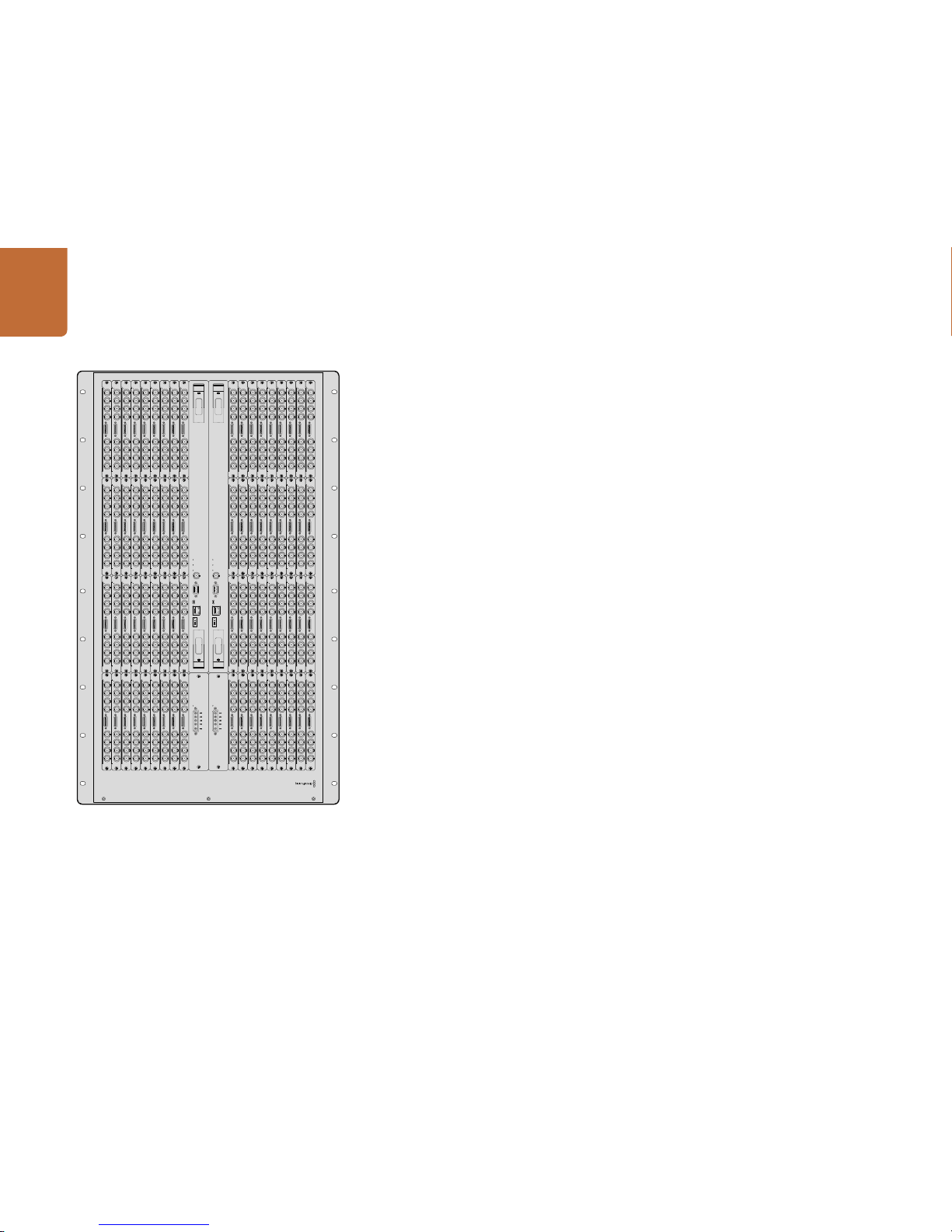
Universal Videohub 288
What you need to get started
Universal Videohub 288 is a large, modular router ideally suited to ver y large facilities and broadcasters.
It features a 72 card rack frame that can be filled with any combination of BNC SDI or optical fiber SDI
interface cards.
When fully populated with t wo Universal Videohub 288 Crosspoint cards, two power cards, 72 interface
cards and 72 deck control cables, Universal Videohub 288 provides 288 SDI input s, 288 SDI outputs, 288
bidirectional RS-422 deck control ports, reference input, redundant crosspoint processor, redundant
Ethernet networking, redundant power and power ful Videohub routing control software for Mac OS X
and Windows.
Occasionally, the internal software of the Universal Videohub 288 will need to be updated. Videohub
Setup will prompt you if an update is required. The utility uses the USB 2.0 connection and you will need
to provide a USB 2.0 type A to mini B male cable.
Universal Videohub 288 ships as an empt y rack frame, except for a removable fan tray and f ans. All other
hardware comp onents, such as SDI interface cards and power supplies, must be purchased and ins talled
separately. Read the following section to help you decide which components you will need before you
build your Universal Videohub 288.
Pages 42-43 provide information on the different interface cards available for your Universal Videohub.
ALARM
POWER OVERLOAD
ALARM
REF IN
RS-422
CONTROL
ETHERNET
USB DIAGNOSTIC
ALARM
POWER OVERLOAD
ALARM
REF IN
RS-422
CONTROL
ETHERNET
USB DIAGNOSTIC
MAIN POWER
+12V 800W
MAIN POWER
+12V 800W
Page 31

31
Using Videohub Routers
ALARM
REF IN
RS-422
CONTROL
USB DIAGNOSTIC
ETHERNET
POWER OVERLOAD
Universal Videohub 288 Crosspoint Card
This module contains the crosspoint processor for switching video routes and changing deck control
ports. Ethernet, USB and serial ports are located on the card for router control.
A Reference input is located on the card for connection to a tri-level sync or black burst genlock signal.
An Alarm light will illuminate on the card if user intervention is required, e.g., if inadequate cooling has
caused Videohub to overheat. Alarm notification is supplied by the GPI (General Purpose Interface)
output to other devices.
A Power Overload light will illuminate on the card if inadequate power is being supplied to the unit for
the number of cards installed.
You will need a number 01 size Pozidriv screwdriver to ins tall the Universal Videohub 288 Cros spoint card.
Router Control Cable
Remote router control is performed via 10/100Base-T Ethernet or serial. If router control is performed
via Ethernet, the integrated Videohub Server is used. This means you only need to provide an Ethernet
cable to connect Universal Videohub 288 to your Ethernet network switch.
Third part y router controllers can control Universal Videohub 288 via Ethernet, or as an RS-422 slave
device, for router crosspoint switching. Please refer to the Developer Information section of this manual
for Videohub and RS-422 protocols.
Power Supply
When fully populated and running at maximum power consumption, Universal Videohub 288 can be
powered by a single Universal Videohub Power Supply.
The Universal Videohub Power Supply package includes a power card with a single connection to a
1 RU size rack mount chassis which contains the power supply.
The Universal Videohub Power Supply chassis contains a universal power supply for use in all countries.
You will need to provide a standard IEC cord with a C13 connector.
Universal Videohub 288 Crosspoint card
Universal Videohub Power Sup ply includes a power card,
1 RU chassis and connecting power cable.
Serial Cable
Standard RJ45 Ethernet Cable
Universal Videohub Power Supply
MAIN POWER
GND
GND
+12V
+12V
+12V
Page 32

32
Using Videohub Routers
Building Universal Videohub 288
25 rack units of space should be reserved for the installation of Universal Videohub 288 and two rack
mount power supply chassis, allowing free space for heat dissipation. Only 23 RU is required if Universal
Videohub 288 is mounted at the top of an open rack as heat can be dissipated from the top.
Universal Videohub 288 is 18 RU high and 6 inches thick. You can rack mount Universal Videohub 288
facing forwards or reversed, or even mount it in the rear of the rack to leave space for other equipment.
Universal Videohub 288 contains elec trostatic sensitive devices. It is essential to discharge yourself of
static elec tricity before handling any of these devices, just as you would when installing devices into
a computer. We recommend the use of an antistatic wrist strap when handling any of these devices.
Installing a Universal Videohub 288 Crosspoint Card
Now that your Univer sal Videohub 288 has been mounted in a rack , it needs to be fitted with a crosspoint
card. The crosspoint card is the brains of Universal Videohub and performs video route and d eck control
switching. Universal Videohub 288 Crosspoint cards are hot-swappable, meaning they are designed to
be installed and removed while the Universal Videohub is running.
Step 1: Hold the cros spoint card in a vertical orientation by its two levers. The BNC , Ethernet and other
ports should be towards the bottom end of the card.
Step 2: Gently inser t the card into its slot, ensuring the top and bot tom edges follow the black guid es.
Step 3: Firmly push both levers flat to fully engage the multi-pin connectors with the motherboard.
Mating pins ensure that the card precisely engages with the motherboard without damaging
the multi-pin connectors.
Step 4: Use a number 01 size Pozidriv screwdriver to secure the two levers on the crosspoint card.
It is common to install a second crosspoint card for failover redundancy and we recommend doing this.
If two crosspoint cards are installed, all video routes and port labels will be safely retained even if one
card becomes faulty and has to be replaced. To remove the blanking plate from the right crosspoint
card slot, you will need to use a number 02 size Pozidriv screwdriver.
Universal Videohub 288 frame
Page 33

33
Using Videohub Routers
Installing Interface cards
Installing a Universal Videohub SDI Interface or Universal Videohub Optical Interface is easy and the
steps are the same for installing each type of interface card.
Step 1: Hold the card in a vertical orientation with the identification LED at the top of the card.
The identification LED looks like a pin hole near the top left of the top connector.
Step 2: Gently inser t the card along its guides until it plug s firmly into the PCI slot on the motherboard.
Step 3: Use a number 02 size Pozidriv screwdriver to secure the card to the Universal Videohub frame.
Pages 42-43 provide information on the different interface cards available for your Universal Videohub.
Installing a Universal Videohub Power Supply
The Universal Videohub Power Supply package consists of a power card, a power cable and a 1 RU
chassis containing the power supply. A second Universal Videohub Power Supply can be installed under
the first power supply for failover redundancy. You will need to provide a standard IEC cord with a C13
connector for each power supply.
Step 1: Ensure that any new power supplies are disconnec ted from any electrical source. Orient the
power card so that the MAIN POWER label appears at the top of the card.
Step 2: Insert the power card into either of the two power card slots.
Step 3: Use a number 02 size Pozidriv screwdriver to secure the power card with its two screws. If you
have a second power card, install it now into the spare power card slot.
Step 4: Connect t he power cable from the power c ard to the power supply. Tighten the thumb screws
on both power connector s. Repeat this step if you have a seco nd power card and second power
supply. It does not mat ter which power card connects to which power supply.
Step 5: Connect an IEC cord from each power supply to a mains wall socket and turn on the power.
Congratulations! Your Universal Videohub 288 is now ready to start routing video!
MAIN POWER
+12V 800W
The Universal Videohub Power Supply consist s of a power
card whic h is inser ted into the Universal Videohub 288 and
then connected to a 1 RU chassis located under the Univers al
Videohub 288.
Installing a Univer sal Videohub SDI Interface Card.
Page 34

34
Using Videohub Routers
MAIN POWER
GND
GND
+12V
GND
+12V
GND
GND
+12V
GND
150W
150W
150W
Installing a Universal Videohub 450W Power Card
While designed for the Universal Videohub 72, the lower cost Universal Videohub 450W Power Card can
be used as a low power supply option for Universal Videohub 288.
The Universal Videohub 450W Power Card requires three 150W brick power supplies, which are sold
separately. This power option may be considered due to it s lower cost but is slightly underpowered and
will not power a fully populated Univer sal Videohub 288 under all card combinations. This power supply
should only be considered if attempting to minimize the cost of purchasing a Universal Videohub 288.
A second Univer sal Videohub 450W Power C ard with three power brick s can be connected to th e Universal
Videohub 288 to ensure continued operation should the first power card fail.
Step 1. Orient the power card so that the MAIN POWER label appears at the top of the card.
Step 2. Inser t the power card into its slot on t he motherboard. Use a numb er 02 size Pozidriv screwdriver
to secure the power card with its two screws.
Step 3. Check the Power Overload light on the crosspoint card. If the Power Overload light is on, you
will have to remove some c ards to ensure that all installe d cards are receiving power. If the Power
Overload light continues to illuminate even after verifying that all three brick power supplies
are working, Universal Videohub 288 has been populated with too many cards. You will need
to discard your low power supply and upgrade to a Universal Videohub Power Supply.
Installing a Universal Videohub 150W Power Supply
The Universal Videohub 150W Power Supply is a brick style power supply which connec ts to a Universal
Videohub 450W Power Card. You will need to connect 3 power supplies for each Universal Videohub
450W Power Card you install in a Universal Videohub 288. You will need to provide a standard IEC cord
with a C13 connector for each power supply.
Adding a Universal Videohub 150W Power Supply
Step 1. Ensure that any new brick power supplies are disconnected from any electrical source.
Step 2. Connec t each new power supply to the Universal Videohub 450W Power Card.
Step 3. Tighten the thumb screws on all power connectors.
Step 4. Connect an IEC cord from each new power supply to the wall socket and turn on the power.
If you need to remove or replace a power brick while Universal Videohub 288 is still running from a
second power card and set of power supplies, power off the brick while being careful to avoid switching
off power to the remaining power supplies. Unplug the IEC cord and then unscrew and disconnect the
power supply from the Universal Videohub 450W Power Card.
Universal Videohub 450W Power Card can be connected to
three 150W power bricks.
Page 35

35
Using Videohub Routers
Installing a second Power Supply while Universal Videohub 288 is running
If you wish to install a redundant or replacement power supply while Universal Videohub 288 is already
running from a power supply, please carry out the installation procedure in the following order:
Step 1. Ensure that the new power supply is disconnected from any electrical source.
Step 2. Orient the new power card so that the MAIN POWER label appears at the top of the card.
Now insert the power card into the spare power card slot.
Step 3. Use a number 02 size Pozidriv screwdriver to secure the power card with its two screws.
Step 4. If you are installing a redundant power supply for the first time, install the 1 RU chassis below
the first power supply, leaving 1 RU of clearance between the two power supplies for heat
dissipation. If you are installing a replacement power supply, install the replacement 1 RU
chassis where the faulty unit was previously located.
Step 5. Connect the new power cable between the connectors on the new power card and the new
power supply. Tighten the thumb screws on both power connectors.
Step 6. Connect an IEC cord from the new power supply to the wall socket and turn on the power.
Removing a Power Supply while Universal Videohub 288 is running
If you need to remove a faulty power supply while Universal Vid eohub 288 is running from another power
supply, please carry out the removal procedure in the following order:
Step 1. Switch off the power to the fault y power supply and unplug its IEC cord.
Step 2. Disconnect the power cable between the power card and the faulty power supply.
Step 3. Remove the faulty 1 RU chassis and associated power card. Ensure all components from the
faulty unit are placed some where where they will not be confu sed with a new replacement uni t.
MAIN POWER
+12V 800W
MAIN POWER
+12V 800W
Two Universal Videohub Power Supplies can be installed for
power redundanc y with the Universal Videohub 288.
Page 36

36
Using Videohub Routers
Installing a Universal Videohub 72 Crosspoint Card
A single Universal Videohub 72 Crosspoint card can be installed in the left crosspoint card slot of a
Universal Videohub 288. The Universal Videohub 72 Crosspoint card is limited to supporting
18 interface cards and does not support crosspoint redundancy. This card should only be
considered if attempting to minimize the initial cost of purchasing a Universal Videohub 288.
When using a Universal Videohub 72 Crosspoint card, only the bottom row of 18 interface
cards can be used. A Universal Videohub 288 Crosspoint card must be used if you want to
install more than 18 interface cards.
The short length of the Universal Videohub 72 Crosspoint card, compared with the Universal Videohub
288 Crosspoint card, requires the installation of an additional suppor ting bridge in the center
of the Universal Videohub 288. When upgrading to a Unive rsal Videohub 288 Cro sspoint card
at a later time, the additional supporting bridge must be removed.
The additional suppor ting bridge, short blanking plate and as sociated screws are available as a separate
package from your Videohub dealer. Torx T8, Torx T10, number 01 and number 02 size
Pozidriv screwdr ivers are required to install t he additional suppor ting bridge and the Univer sal
Videohub 72 Crosspoint card.
Step 1. Ensure power is switched off and disconnec ted from Universal Videohub 288.
Step 2. Use a num ber 02 size Pozidriv screwdriver to re move the blanking plate from the rig ht crosspoint
card slot.
Step 3. Use a number 02 size Pozidriv screwdriver to remove the blanking plates from the interface
card slots for SDI ports 73-216.
Step 4. Maneuver the supporting bridge through the crosspoint card slots and rest it flat on the
motherboard, with the card guides facing up, while taking great care to avoid damaging the
multi-pin connectors on the motherboard.
Step 5. Stand the suppor ting bridge so the holes in its left and right feet are positioned over the
corresponding mounting holes on the motherboard standoffs. The card guides should face
the lower supporting bridge at the bot tom of the crosspoint slots.
Step 6. Secure the lef t and right feet of the suppor ting bridge with the number 02 size Pozidriv screw s.
Ste p 7. Secure the lef t and right legs of the supporting bridge with the two Torx T10 screws as shown
in the accompanying illustration. These screws are installed horizontally.
Page 37

37
Using Videohub Routers
Step 8. Use a Torx T8 screwdriver to remove the silver catches from the t wo supporting bridges at
the top and bottom of the left crosspoint slot. In the accompanying illustration, the letter
"A" indicates the location on the left side of the supporting bridges where the silver catches
have been removed. When upgrading to a Universal Videohub 288 Crosspoint card at a later
time, you will need to reins tate the silver catches, so make sure you keep them in a safe place.
The silver catches shown at "B" should not be removed. They will be required if installing a
Universal Videohub 288 Crosspoint card in the right crosspoint card slot in the future.
St ep 9. To install the Universal Videohub 72 Crosspoint card, hold the card in a ver tical orientation
by its two levers. The BNC, Ethernet and other ports should be towards the bottom end
of the card. Gently insert the unit into its slot, below the additional supporting bridge, and
ensure the top and bottom edges of the card follow the black guides. Now firmly push
both levers flat to fully engage the multi-pin connectors with the motherboard. Mating pins
ensure that the card precisely engages with the motherboard without damaging the multipin connectors. Use a number 01 size Pozidriv screwdriver to secure the screws on the two
levers of the crosspoint card.
Ste p 10. The short length of the Universal Videohub 72 Crosspoint card means that a short blanking
plate should also be installed to cover the rest of the long crosspoint slot. The short blanking
plate can be secured with a number 02 size Pozidriv screwdriver.
St e p 11. Use a number 02 size Pozidriv screwdriver to rein state the blanking plate for the r ight cross point
card slot.
Step 12. Reinstate the blanking plates for the interface card slots for SDI ports 73-216. Interface cards
must only be installed in the bottom row, for SDI por ts 1-72, when a Universal Videohub 72
Crosspoint card is used.
Page 38

38
Using Videohub Routers
Universal Videohub 72
What you need to get started
Universal Videohub 72 is a medium-sized modular router ideal for growing facilities. It feature s an 18 card
rack frame that can be filled with any combination of BNC SDI or optical fiber SDI interface cards. When
fully populated with a crosspoint card, a power card, 18 SDI interface cards and 18 deck control cables,
Universal Videohub 72 provide s 72 SDI inputs, 72 SDI ou tputs, 72 bidirectional RS -422 deck control ports,
reference input, redundant power supply options and powerful Videohub routing control software for
Mac OS X and Windows.
Occasionally, the internal software of the Universal Videohub 72 will need to be updated. Videohub
Setup will prompt you if an update is required. The utility uses the USB 2.0 connec tion and you will need
to provide a USB 2.0 type A to mini B male cable.
Universal Videohub 72 ships as an empty rack frame, except for a removable fan tray and fans. All other
hardware components, including SDI interface cards, deck control cables, crosspoint card and power
supplies must be purchased and installed separately. SDI interface cards can be purchased as your
facility grows and don't need to be installed all at once. This sec tion is designed to help you decide
which components you will need before you build your Universal Videohub 72.
Pages 42-43 provide information on the different interface cards available for your Universal Videohub.
MAIN POWER
+12V
150W
150W
150W
POWER OVERLOAD
ALARM
REF IN
RS-422
CONTROL
ETHERNET
USB DIAGNOSTIC
Page 39

39
Using Videohub Routers
POWER OVERLOAD
ALARM
REF IN
MAIN POWER
GND
GND
+12V
GND
+12V
GND
GND
+12V
GND
150W
150W
150W
Universal Videohub 72 Crosspoint Card
This module contains the crosspoint processor for switching video routes and changing deck control
ports. Ethernet, USB and serial ports are located on the card for router control.
A Reference input is located on the card for connection to a tri-level sync or black burst genlock signal.
An Alarm light will illuminate on the card if user intervention is required, e.g., if inadequate cooling has
caused Videohub to overheat. Alarm notification is supplied by the GPI (General Purpose Interface)
output to other devices.
A Power Overload light will illuminate on the card if inadequate power is being supplied to the unit for
the number of cards installed.
Router Control Cable
Remote router control is performed via 10/100Base-T Ethernet or serial. If router control is performed
via Ethernet, the integrated Videohub Server is used. This means you only need to provide an Ethernet
cable to connect Universal Videohub 72 to your Ethernet network switch.
Third party router controllers can control Universal Videohub 72 via Ethernet, or as an RS-422 slave
device, for router crosspoint switching. Please refer to the Developer Information section of this manual
for Videohub and RS-422 protocols.
Power Supply
The Universal Videohub 450W Power Card provides connec tions for up to three 150W brick-st yle power
supplies, which must be purchased separately.
When fully populated and running at maximum power consumption, Universal Videohub 72 can be
powered by two 150W brick power supplies. A third power supply can be connec ted to ensure continued
operation should one power su pply fail. The 150W power supplies are universal power supplies for use in
all countries. You will need to provide a standard IEC cord with a C13 connector for each power supply.
When fully populated with three power supplies, three mains power sockets will be required.
The high power supply designed for Universal Videohub 288 is ill-suited to Universal Videohub 72
because it doesn't provide power redundancy to Universal Videohu b 72, is more expensive and requires
an additional 1 RU of space below Universal Videohub 72.
Universal Videohub 72 Crosspoint card
Serial Cable
Standard RJ45 Ethernet Cable
Universal Videohub 450W Power Card can be connected to
three 150W power bricks
Page 40

40
Using Videohub Routers
Building Videohub 72
9 rack units of space should be reserved for the installation of Universal Videohub 72 including access
space for the drop-down fan tray as well as free space for heat dissipation. Only 7 RU is required if
Universal Videohub 72 is mounted at the top of an open rack. Universal Videohub 72 is 5 rack units high
and 6 inches thick. You can rack-mount Universal Videohub 72 facing forwards or reversed, or even
mount it in the rear of the rack to leave space for other equipment. 2 RU of space should be left above
Universal Videohub 72 for heat dissipation unless mounted at the top of an open rack where there is no
obstruction to airflow above.
Universal Videohub 72 contains electrostatic sensitive devices. It is essential to discharge yourself of
static elec tricity before handling any of these devices, just as you would when installing devices into
a computer. We recommend the use of an antistatic wrist strap when handling any of these devices.
Installing a Universal 72 Crosspoint Card
Now that your Univer sal Videohub 72 has been mounted in a rack, it needs to be fit ted with a crosspoint
card. The crosspoint card is the brains of any Universal Videohub and performs video route and deck
control switching. Universal Videohu b 72 Crosspoin t cards are hot-swappable, meaning they are designed
to be installed and removed while the Universal Videohub is running.
Step 1: Hold the cros spoint card in a vertical orientation by its two levers. The BNC , Ethernet and other
ports should be towards the bottom end of the card.
Step 2: Gently inser t the card into its slot, ensuring the top and bot tom edges follow the black guid es.
Step 3: Firmly push both levers flat to fully engage the multi-pin connectors with the motherboard.
Mating pins ensure that the card precisely engages with the motherboard without damaging
the multi-pin connectors.
Step 4: Use a number 01 size Pozidriv screwdriver to secure the two levers on the crosspoint card.
Installing Interface cards
Installing a Universal Videohub SDI Interface or Universal Videohub Optical Interface is easy and the
steps are the same for installing each type of interface card.
Step 1: Hold the card in a ver tical orientation with the identification LED at the top of the card. The
identification LED looks like a pin hole near the top lef t of the top connector.
Step 2: Gently but firmly insert the card so that it follows its guides and plugs into the PCI slot in the
motherboard. Use a number 02 size Pozidriv screwdriver to secure the interface card to the
Universal Videohub frame.
Pages 42-43 provide information on the different interface cards available for your Universal Videohub.
Installing a Universal Videohub 72 Crosspoint Card.
Installing a Univer sal Videohub SDI Interface.
Page 41

41
Using Videohub Routers
Installing a Universal Videohub 450W Power Card
The Universal Videohub 450W Power Card features three power connectors, which can be connec ted
to 150W power supply bricks for up to 450W of power. This power card is suitable for powering a fully
populated Universal Videohub 72 with two power supplies connected. A third connected power supply
provides failover redundancy should one power supply fail.
Step 1: Ensure that the power supply is disconnec ted from any electrical source.
Step 2: Orient the power card so that the MAIN POWER label appears at the top of the card.
Step 3: Insert t he power card into its slot on the motherbo ard. Use a number 02 size Pozidriv screw driver
to secure the power card with its two screws.
Step 4: Connect three Universal Videohub 150W Power Supplies.
If you need to remove or replace the power c ard, power off and disconnect all connected power supplies
before removing the power card.
If you have only partially populated your Universal Videohub 72 with interface cards, you might be able
to power it with a single 150W power supply and preferably use a second power supply for failover
redundancy. If you choose this option:
Step 1: Temporarily disconnect the second power supply and then check the Power Overload light
on the crosspoint card af ter installing any cards.
Step 2: If the Power Overload light illuminates, you will have to add a 150W brick power supply or
remove some cards to ensure that all cards are receiving power.
Step 3: Reco nnect the second po wer supply when you have finis hed checking the Power Over load light.
For peace of mind, we recommend connec ting and powering the three power supplies at all times to
ensure sufficient power, and power redundancy, with all card combinations.
If you need to remove or replace a 150W Power Supply while Universal Videohub 72 is still running,
power off the brick while being careful to avoid switching off power to the remaining power supplies.
Unplug the IEC cord and then unscrew and disconnect the power supply from the Universal Videohub
450W Power Card.
Congratulations! Your Universal Videohub 72 is now ready to start routing video!
MAIN POWER
GND
GND
+12V
GND
+12V
GND
GND
+12V
GND
150W
150W
150W
Universal Videohub 450W Power Card can be connected to
three 150W power bricks.
Page 42

42
Using Videohub Routers
SDI Interface Card
SDI interface cards feature 4 SDI inputs, 4 SDI outputs and a connector for a Universal Videohub Deck
Control Cable. All SDI connections support auto detection of SD, HD or 3G-SDI, and reclocking on
all SDI outputs. Simultaneous routing of 2K, HD, SD video and DVB-ASI are supported with Universal
Videohub. SDI interface cards are designed to be installed while Videohub is running and become
active immediately. They do not require Videohub to be power cycled. You will need a number 01 and
a number 02 size Pozidriv screwdriver to install the various cards.
There are two models of SDI inter face cards that can be used with Universal Videohub:
Universal Videohub SDI Interface card with BNC connectors.
Universal Videohub Optical Interface card has standard SFP transceiver modules with 1310
nm laser drivers and receivers. Each module includes an LC connector port to be used
with single-mode optical fiber cables.
Universal Videohub Deck Control Cable
This cable features a single serial port at one end, for connection to both types of SDI interface cards,
and four RS-422 deck control ports at the other end.
Universal Videohub Deck Control Cable
Universal Videohub Optic al Interface card
Universal Videohub SDI Interface card
Page 43

43
Using Videohub Routers
Universal Videohub Interface Cards
MAIN POWER
+12V 800W
MAIN POWER
+12V
150W 150W 150W
POWER OVERLOAD
ALARM
REF IN
POWER OVERLOAD
ALARM
REF IN
RS-422
CONTROL
ETHERNET
USB DIAGNOSTIC
Output 1
Output 2
Output 3
Output 4
Input 1
Input 2
Input 3
Input 4
Activity light
Universal Videohub
Deck Control
Cable connector
Universal Videohub
SDI Interface
MAIN POWER
+12V 800W
MAIN POWER
+12V
150W 150W 150W
POWER OVERLOAD
ALARM
REF IN
POWER OVERLOAD
ALARM
REF IN
RS-422
CONTROL
ETHERNET
USB DIAGNOSTIC
Output 4
Input 4
Output 3
Input 3
Activity light
Universal Videohub
Deck Control
Cable connector
Universal Videohub
Optical Interface
Output 2
Input 2
Output 1
Input 1
Page 44

44
Using Videohub Routers
Broadcast Videohub
Broadcas t Videohub is perfe ct for large facilities. It features 72 SDI input s, 144 SDI outputs, 72 bidirec tional
RS-422 deck control ports, reference input, redundant power supplies and powerful Videohub routing
control software for Mac OS X and Windows.
All SDI connections support auto detection of SD, HD or 3G-SDI, and reclocking on all SDI inputs.
Simultaneous routing of 2K, HD, SD video and DVB-ASI are supported with Broadcast Videohub.
Remote router control is performed via USB 2.0 and then shared over an IP network in much the same
way as USB printer sharing. Prior to connecting any devices to Broadcast Videohub, you must nominate
a computer to be the Videohub “Server” and to perform Videohub sharing via USB. You can use almost
any computer for the Videohub Server, such as an editing workstation, and you don’t need a dedicated
or powerful computer for this task. However the Videohub Server computer must remain powered on
at all times so that Videohub settings can be modified. You will need to provide a standard USB 2.0 type
A-B male cable to connect Broadcast Videohub to the server computer.
The same USB cable can be used for applying occasional internal soft ware updates. Videohub Setup
will prompt you if an update is required. The utility runs on the Videohub Server computer and uses the
USB 2.0 connection to update your Videohub.
Third part y router controllers can control Broadc ast Videohub via Ethe rnet for router crosspoint switching.
The Videohub Ethernet protocol is documented in the Developer Information section of this manual.
Broadcast Videohub is 8 rack units high and less than 3 inches deep, including power connector and
cable. You will need to leave enough space in your equipment rack to install the Broadcast Videohub
hardware. You can rack-mount Broadcast Videohub facing forwards or reversed, or even mount it in the
rear of the rack to leave space for other equipment.
The Broadcast Videohub requires one power suppl y but includes two so continued operation is ensured
if one happens to fail. The included power supplies are universal power supplies for use in all countries.
You will need to provide a stand ard IEC cord with a C13 connector for each power su pply. We recommend
connecting and powering the two power supplies at all times, which means two mains power sockets
will be required. A third power socket will be required if you decide to use a dedicated ser ver computer.
If you need to learn how to integrate your router into an existing network, turn to page 7.
Page 45

45
Using Videohub Routers
Studio Videohub
Studio Videoh ub is perfect for smaller workgroups. It features 16 SDI input s, 32 SDI outputs, 16 bidirecti onal
RS-422 deck control ports, reference input, a universal power supply and powerful Videohub routing
control software for Mac OS X and Windows.
All SDI connections support auto detection of SD, HD or 3G-SDI, and reclocking on all SDI inputs.
Simultaneous routing of 2K, HD, SD video and DVB-ASI are supported with Studio Videohub.
Remote router control is performed via USB 2.0 and then shared over an IP network in much the same
way as USB printer sharing. Prior to connecting any devices to Studio Videohub, you must nominate a
computer to be the Videohub “Server” and to perform Videohub sharing via USB. You can use almost
any computer for the Videohub Server, such as an editing workstation, and you don’t need a dedicated
or powerful computer for this task. However the Videohub Server computer must remain powered on
at all times so that Videohub settings can be modified. You will need to provide a standard USB 2.0 type
A-B male cable to connect Studio Videohub to the server computer.
The same USB cable can be used for applying occasional internal soft ware updates. Videohub Setup
will prompt you if an update is required. The utility runs on the Videohub Server computer and uses the
USB 2.0 connection to update your Videohub.
Third part y router controllers can control Studio Videohub via Ethernet for router crosspoint switching.
The Videohub Ethernet protocol is documented in the Developer Information section of this manual.
Studio Videohub is 2 rack units high and less than an inch thick. You will need to leave enough space
in your equipment rack to install the Studio Videohub hardware. You can rack-mount Studio Videohub
facing forwards or reversed, or even mount it in the rear of the rack to leave space for other equipment.
If you don’t have a rack, then you can leave it in a safe place on the floor!
The Studio Videohub includes a universal power supply for use in all countries. You will need to provide
a standard IEC cord with a C13 connector and a mains power socket. A second power socket will be
required if you decide to use a dedicated ser ver computer.
If you need to learn how to integrate your router into an existing network, turn to page 7.
Page 46

46
Using Videohub Routers
Compact Videohub
Compact Videohub is a small router and is perfec t when you need a bigger router in a small size, such as
in creative post facilities and broadcast trucks. It features 40 SDI inputs, 40 SDI outputs, reference input,
redundant power supply connections and powerful Videohub routing control soft ware.
All SDI connections support auto detection of SD, HD or 3G-SDI, and reclocking on all SDI inputs.
Simultaneous routing of 2K, HD, SD video and DVB-ASI are supported with Compact Videohub.
Remote router control is performed via 10/100Base-T Ethernet, serial or USB 2.0 and then shared over
an IP network in much the same way as USB printer sharing. If router control is performed via Ethernet,
the integrated “Videohub Server” is used and you need only provide an Ethernet cable to connect
Compact Videohub to your Ethernet network switch.
If router control is performed via USB 2.0, you must nominate a computer to be the “Videohub Server”
and to perform Videohu b sharing via USB. You can use almos t any computer for the Videohu b Server and
you don’t need a dedicated or powerful computer for this task. However the Videohub Server computer
must remain powered on at all times so that Videohu b settings can be modi fied. You will need to provide
a standard USB 2.0 type A-B male cable to connect Compact Videohub to the server computer.
The same USB cable can be used for applying occasional internal soft ware updates. Videohub Setup
will prompt you if an update is required. The utility runs on the Videohub Server computer and uses the
USB 2.0 connection to update your Videohub.
Third part y router controllers can control Compac t Videohub via Ethernet, or as an RS- 422 slave device,
for router crosspoint switching. The Videohub Ethernet protocol, RS- 422 protocol and RS-422 pinout
diagram are documented in the Developer Information section of this manual.
Compac t Videohub is 2 rack unit s high and less than an inch thick. You will need to leave enough space in
your equipment rack to install the Compact Videohub hardware. You can rack-mount Com pact Videohub
facing forwards or reversed, or even mount it in the rear of the rack to leave space for other equipment.
If you don’t have a rack, then you can leave it in a safe place on the floor!
The Compac t Videohub includes one universal power supply for use in all countries. A second power
supply can be purchased to ensure continued operation should one fail. You will need to provide a
standard IEC cord with a C13 connector for eac h power supply. We recommend connec ting and powering
two power supplies at all times, which means two mains power sockets will be required. A third power
socket will be required if you decide to use a dedicated server computer.
If you need to learn how to integrate your router into an existing network, turn to page 7.
Page 47

47
Using Videohub Routers
Micro Videohub
Micro Videohub is a tiny router and is perfect for locations where minimal space is available, such as
outside broadcast trucks. It features 16 SDI inputs, 16 SDI outputs, reference input, a universal power
supply and powerful Videohub routing control sof tware for Mac OS X and Windows.
All SDI connections support auto detection of SD, HD or 3G-SDI, and reclocking on all SDI inputs.
Simultaneous routing of 2K, HD, SD video and DVB-ASI are supported with Micro Videohub.
Remote router control is performed via 10/100Base-T Ethernet, serial or USB 2.0 and then shared over
an IP network in much the same way as USB printer sharing.
If router control is performed via Ethernet, the integrated “Videohub Server” is used and you need only
provide an Ethernet cable to connect Micro Videohub to your Ethernet network switch.
If router control is performed via USB 2.0, you must nominate a computer to be the “Videohub Server”
and to perform Videohub sharing via USB. You can use almost any computer for the Videohub Server,
such as an editing workstation, and you don’t need a dedicated or power ful computer for this task.
However the Videohub Ser ver computer must remain powered on at all times so t hat Videohub setting s
can be modified. You will need to provide a standard USB 2.0 type A-B male cable to connect Micro
Videohub to the server computer.
The same USB cable can be used for applying internal software updates. Videohub Setup will prompt
you if an update is required. The utility runs on the Videohub Server computer and uses the USB 2.0
connection to update your Videohub.
Third part y router controllers can control Micro Videohub via Ethernet, or as an RS-422 slave device,
for router crosspoint switching. The Videohub Ethernet protocol, RS- 422 protocol and RS-422 pinout
diagram are documented in the Developer Information section of this manual.
Micro Videohub is 1 rack unit high and less than an inch thick. You will need to leave enough space in
your equipment rack to install the Micro Videohub hardware. You can rack-mount Micro Videohub facing
forwards or reversed, or even mount it in the rear of the rack to leave space for other equipment. If you
don’t have a rack, then you can leave it in a safe place on the floor!
The Micro Videohub includes a universal power supply for use in all countries. You will need to provide
a standard IEC cord with a C13 connector and a mains power socket. A second power socket will be
required if you decide to use a dedicated ser ver computer.
If you need to learn how to integrate your router into an existing network, turn to page 7.
Page 48

48
Using Videohub Routers
Smart Videohub
Smart Videohub is a tiny router with a built in control panel for changing routes and is perfect for loc ations
where minimal space is available, such as outside broadcast trucks. It features 16 SDI inputs, 16 SDI
outputs, reference input, a universal power supply and powerful Videohub routing control software.
All SDI connections support auto detection of SD, HD or 3G-SDI, and reclocking on all SDI inputs.
Simultaneous routing of 2K, HD, SD video and DVB-ASI are supported with Smar t Videohub.
Local router control is easy and intuitive using the built in 32 pushbutton control panel, and requires no
configuration and no computer. The front panel can be removed to allow inser tion of labels under the
buttons. All buttons can be variably backlit to ensure the labels can be easily read, even in dark rooms.
Remote router control can also be per formed via 10/100Base-T Ethernet, serial or USB 2.0 and then
shared over an IP network in much the same way as USB printer sharing. If router control is performed
via Ethernet, the integrated “Videohub Server” is used and you need only provide an Ethernet cable to
connect Smart Videohub to your Ethernet network switch.
If remote router control is performed via USB 2.0, you must nominate a computer to be the “Videohub
Server” and to perform Videohub sharing via USB. You can use almost any computer for the Videohub
Server and you don’t need a ded icated or powerful computer for this task. However the Videohub Server
computer must remain powered on at all times so that Videohub settings c an be modified. You will need
to provide a standard USB 2.0 type A-B male cable to connect Smart Videohub to the server computer.
The same USB cable can be used for applying internal software updates. Videohub Setup will prompt
you if an update is required. The utility runs on the Videohub Server computer and uses the USB 2.0
connection to update your Videohub.
Third part y router controllers can control Smart Videohub via Ethernet, or as an RS-422 slave device, for
router crosspoint switching.
Smart Videohub is 1 rack unit high and just over an inch thick. You will need to leave enough space in
your equipment rack to install the Smart Videohub hardware. You can rack-mount Smart Videohub at
the front or at the rear of the rack to leave space for other equipment.
The Smart Videohub includes a universal power supply for use in all countries. You will need to provide
a standard IEC cord with a C13 connector and a mains power socket. A second power socket will be
required if you decide to use a dedicated ser ver computer.
Turn the page to Using Smart Videohub’s Control Panel for instructions on how to make route changes
with the 32 pushbutton control panel. Alternatively, if you need to learn how to integrate your router
into an existing network, turn to page 7.
Page 49

49
Using Videohub Routers
Using the Smart Videohub Control Panel
Smart Videohub featu res a built in 32 pushbutton control panel on t he front of the router. Routing changes
can be made without needing a computer as there is a pushbutton for each SDI input and output on
Smart Videohub. Remote router control can also be used with Smart Videohub.
The pushbuttons on the left of the control panel corre spond with the 16 SDI inputs and the pushbut tons
on the right correspond with the 16 SDI outputs.
When power is connected to Smart Videohub, the top-left destination button will illuminate white along
with its corresponding source but ton.
To change routes:
Step 1. Select a destination button and its corresponding source button will illuminate.
Step 2. Press the desired video source button to connect a new source to the destination.
The original source button’s LED will turn off and the new source but ton will light up. The
new video source will immediately be connected and viewable on the destination device,
such as an SDI monitor.
Step 3. To change another route, sel ect another dest ination button and then s elect a new source but ton.
The pushbuttons on Smart Videohub direc tly control the integrated Videohub Server and override any
existing routes, including destinations locked with Videohub software.
The illuminated pu shbuttons display the last route mad e with the Smart Videohub control panel. However,
if you select the same destination pushbutton as another remote user and they change the source to
that destination, you will see the change reflected on your Smart Videohub.
The built in pushbutton control panel allows routing changes
to be made without the need for a computer.
Every pushbut ton on the front panel of Smart Videohub has a
matching SDI input or output on t he rear panel.
Page 50

50
Controlling Videohub with Software
Blackmagic Videohub Control
Launch Videohub Control and click on Settings (the gear icon) and choose "Select Videohub" from
the menu. Click on the Videohub that you wish to control. If you completed the section on customizing
labels, the names you assigned will appear within the software.
If the Input, Output and Remote connections have not yet already been labeled, then the source
pushbut tons will appear simply as "Inpu t", followed by their res pective numbers. Likewise, the de stination
pushbuttons will appear as "Output", followed by their respec tive numbers. These inputs and outputs
correspond to the connector numbers on the Videohub.
Getting to Know the Interface
Resizing the Interface
Click and drag the bottom right hand corner to proportionally resize the interface to best fit your screen
size. Alternatively, drag a window edge to resize either ver tically or horizontally.
Resizing the Sources and Destinations Areas
Drag the Divider Bar up and down and use the Scroll Bars to scroll the respective areas.
Switching Views
You can switch between pushbutton view and list view by clicking the icons in the bottom right corner.
Using the Dynamic Search
Both the Sources and Destinations areas contain a search icon, which allows you to search for text
dynamically. This is useful if you have many pushbuttons and quickly want to locate a pushbutton with a
specific name. Begin by typing the name you wish to search for. As you type each letter, the pushbuttons
that are displayed will be dynamically filtered.
The word "ATEM" is entered into the De stinations Searc h Box
and the filtered results are displayed.
Click on the "Select V ideohub" button and then select the
Videohub you wish to control.
Controlling Videohub with Software
Page 51

51
Controlling Videohub with Software
Blackmagic Videohub Control at a Glance
Click and drag the window edge s to resize Blackmagic Videohub Control to fit your screen size. Drag the Divider Bar up
or down to reveal more or less of the "Sources" and "Destinations" areas and use the Sc roll Bars to scroll the areas.
Scrollbars indicate
not all pushbuttons
are visible
Title Bar shows
Videohub type
Highlighted Pushbuttons
denote paired connections
Pushbutton View
List View
Sources Area
Destinations Area
Destinations Area
Search
Sources Area Search
Settings
Us e TAKE
Reveal Source
Divider Bar
Page 52

52
Controlling Videohub with Software
Settings Menu
Select Videohub
Select from a list of Videohubs that are currently connected to your network.
Save Layout
Save customized pushbutton layouts for the different environments in which you use your Videohub.
Load Layout
Load previously saved pushbutton layouts.
Edit Buttons
Displays the Edit Buttons for editing the pushbuttons.
Reset All
Displays all of the inputs and outputs of the connected Videohub and replaces customized icons with
the default icon. Source, destination and deck control set tings are maintained.
Edit Buttons
Add
Add a source or destination pushbutton.
Edit
Allows you to set the SDI source or destination, deck control and the icon for the selected pushbutton.
Lock and Unlock
Lock a destination to avoid accidentally changing the video source which is routed to that destination.
If you click on a pushbutton that's locked, the Lock button changes into an Unlock button. Simply click
the Unlock button to unlock the destination pushbutton.
Clear
Deletes source, destination and deck control settings as well as the icon for the selected pushbutton.
Remove
Removes the selec ted pushbutton.
Done
Click the Done button to exit the edit mode.
Click the Setting s button to display the above menu.
Click Edit Bu ttons to display the above buttons.
Page 53

53
Controlling Videohub with Software
Using Pushbuttons
Adding Pushbuttons
Select the Setting s button and then selec t "Edit Buttons". Click on the Add button and choose whether
to add a source or destination pushbutton.
The Set Button window appears and allows you to set the SDI source or destination, RS-422 deck
control and the icon for the pushbutton. In most cases, deck control is grouped with the associated SDI
connections. eg: SDI Input 1 would be associated with the corresponding Remote 1.
Editing Pushbuttons
Select the Settings button, then select "Edit Buttons" and click the pushbutton you wish to edit. Click
on the Edit but ton and modif y the source or destination, deck control settings and the icon as required.
Moving Pushbuttons
Select t he Settings button and then selec t "Edit Buttons". C lick and drag the pushbut ton to a new position.
Viewing and Switching Routes
Viewing Routes
In order to see which video source has been routed to a video destination, such as a monitor, press the
button in the destinations panel to make the button illuminate. The associated video source button will
illuminate in the sources panel, making it immediately o bvious which source is conne cted to the monitor.
Reveal Source
If you select a destination but the source is currently positioned offscreen, clicking the Reveal Source
button will scroll the Sources area to display the source pushbutton.
Switching Routes
In order to change the video source from a tape deck to a video camera, press a camera pushbutton in
the sources panel. The camera pushbut ton will illuminate be routed to the video monitor. The tape deck
button will no longer be illuminated and will be disconnected from the video monitor.
Use TAKE Confirmation before Switching Routes
You may wish to enable the "Use TAKE" button to help prevent unintentional changes to video routes.
Once enabled, any attempt to change a video route using a pushbutton will cause a red "TAKE" button
to appear. Select the button to confirm or click the current source or destination pushbutton to cancel.
The Set But ton window allows icon selec tion, source or
destination selection and deck control configuration.
This des tination is unlocked and is available to any Videohub u ser
on the net work. The asso ciated video sourc e is illuminated in the
Sources panel and the source name "DaVinci" is displayed.
Page 54

54
Controlling Videohub with Software
Locking and Unlocking Routes
Locking a de stination will avoid accident ally changing the video sourc e which is routed to that dest ination.
To lock a route, select the destination pushbut ton and click the Lock but ton. A padlock icon will appear in
the top-right corner of th e destination pushbutton and will preve nt anyone else from using the des tination
device until it is unlocked from your computer. Locking a destination still leaves the associated video
source available for routing to multiple destinations simultaneously.
If you click on a pushbutton that's locked, the Lock button changes into an Unlock button. Simply click
the Unlock button to unlock the destination pushbutton.
To simultaneously lock multiple destinations, shift click the destination pushbuttons you wish to lock
and click the Lock button. If you select a mixture of locked and unlocked pushbut tons, you will have the
option to Lock the unlocked pushbuttons.
Locking a route between an input and an output also locks the RS -422 deck control connection between
the two devices to avoid other users accidentally seizing the deck control belonging to the video source.
The RS-422 connection between the video source and video destination will remain locked until the
destination pushbutton is unlocked.
A black padlock icon will appear on a ny destination pushbuttons whic h other users have locked. The vid eo
destination devices will not be available to you until the destination pushbuttons have been unlocked
from the other users’ computers and iPads.
If you need to unlock a route set by another user, launch Videohub Setup, select the Outputs tab and
click the destination's lock icon.
Remotely locked des tinations display a black padlock icon.
Locally locked destinations display a white padlock icon.
Page 55

55
Controlling Videohub with Software
Touchscreen Computers
The Pushbut ton views are designed to be easy to use and look beautiful on a large, touc hscreen display.
Dedicating a touchscreen computer to the Videohub Pushbutton interface makes it incredibly easy
for users to switch connec tions bet ween multiple SDI devices without having to see every connected
device all of the time. Using a touchscreen computer, in conjunction with Videohub Pushbutton views,
provides the fastest way to switch connections which is perfect for a master control room. Touchscreen
desktop and touchscreen laptop computers can be used. It is a good idea to check the resolution of
your touchscreen display before deciding upon which Pushbutton view to use.
The Pushbutton inter face to Videohub was introduced at the NAB 2009 trade show and displaye d on HP
TouchSmart IQ8 00 computers. Thi s computer model had a 25” display and a res olution of 1920 x 1200 wh ich
was perfect for Full Screen Pushbutton view. Many other brands and models of touchscreen computers
and displays exist and you just need to choose one that provides a resolution matching one of the
Pushbutton views.
Touchscreens are per fect for rapidly selecting and routing input s and outputs but they are cumbersome
for configuring pushbuttons. The width of a human fingertip is much wider than a mouse pointer
and is less accurate when tapping on menu options and small icons. For this reason, we recommend
configuration of Videohub pushbuttons be per formed with a mouse. Once the Videohub pushbuttons
have been configured, it will be easy to use a finger to select and route, inputs and outputs, by tapping
on Videohub pushbuttons.
When a computer mouse is moved to the top-right corner of any Videohub pushbutton, an i icon
appears and clicking the icon opens the Videohub Button Setup window. By contrast, a touchscreen
cannot detec t a hovering finger and so the i icon will not be revealed. Tapping a finger in the top-right
corner of any Videohub pushbutton will open the Videohub Button Setup window on a touchscreen
even though the i icon will not have been revealed.
When a computer mouse is moved to the top of a Full Screen Pushbutton view, the Videohub menu bar
will be revealed. When the mouse is moved away from the menu bar, the menu bar will hide again. As
with the i icon, a touchscreen cannot detect a finger hovering towards the top of the display and so the
Videohub menu bar will not be revealed automatically. Tapping a finger any where above the top row of
source pushbuttons will reveal the Videohub menu bar on a touchscreen. To hide the Videohub menu
bar, simply tap again in the same area.
Touchscreens work a little dif ferently to a computer mouse but provide the fastest and easiest way to
work with th e Videohub Pushbut ton interface and so are hig hly recommended. When us ing a touchscreen
computer, we recommend enabling the Take Confirmation option to help avoid unintentional changes
to video routes.
Page 56

56
Controlling Videohub with Software
Apple iPad
The Videohub Pushbut ton controller interface looks stunning on the high resolution Apple iPad display.
Aside from looking great, it also provides the convenience of portable router control anywhere in your
facility or even over the Internet via a wireless or cellular connection! If you are already familiar with the
Videohub Pushbutton interface on a computer, then there is almost nothing new you need to learn and
you’ll only notice slig ht differences bet ween computer mouse con trol and touchscreen contro l on the iPad.
Up to 40 sources and 8 destinations can be displayed in a single Videohub Pushbutton screen on the
iPad. Even more sources and destinations can be displayed by flicking the iPad left or right, or tapping
to the left or right of the row of dots, to move through multiple Pushbutton screens.
The initial Pushbutton interface
Upon launching the Videohu b app on your iPad for the first time, all pushbut tons initially show the generic
BNC connector icon, which you can then replace from a selection of icons. If the connections have not
yet been labeled, then the source pushbuttons will appear as Input 1 to Input 40 and the destination
pushbuttons will appear as Output 1 to Output 8.
If the connections have already been labeled, their names will appear under each of the respective
pushbuttons in place of the connector numbers.
Configuring Videohub Pushbuttons on the iPad
Configuring V ideohub Pushbuttons on the iPad is easy. Press and hold any Vide ohub pushbutton to op en
the Videohub Button Setup window. This window allows you to set the SDI input or output connection,
RS-422 deck control and the icon for the pushbutton.
The Clear button will delete all settings for the pushbutton. In most cases, deck control is grouped with
the associated SDI connec tions, meaning an SDI connec tion named Input 1 would usually be associated
with the corresponding Remote 1.
The bottom-right source button is reserved by the Videohub app itself and cannot be configured.
If a destination pushbutton is connected to a source that does not appear in the sources panel, the
source will automatically appear in the bottom-right pushbutton of the sources panel.
When configuring pushbuttons, only select a deck control connection for those devices that have
RS-422 deck control. It makes no sense to assign a deck cont rol connection to a video monitor or camera.
While all icons are available to any pushbu tton, it doesn’t make sense to cho ose the icon of a video monitor
or transmit ter for a source pushbut ton unless the source device happens to have a loop-through output.
The Videohub But ton Setup window allows you to set t he SDI
input or output connection, RS- 422 deck control and the icon
for the pushbutton.
Page 57

57
Controlling Videohub with Software
You may choose to show a particular source or destination pushbutton several times within the one
Pushbut ton screen or on multiple Push button screens. If a de stination pushbut ton is routed from a source
that appears multiple times in the Sources panel, selecting the destination pushbutton will illuminate
all instances of the source pushbutton, regardless of how deck control has been configured for each
source pushbutton. Similarly if multiple instances of an output pushbutton appear in the Destinations
panel, they will illuminate together when any one has been selected.
Viewing and Changing Routes
In order to see which video source has been routed to a particular destination, such as a monitor, press
the monitor’s push button in the destinations panel. The monitor button and the associated video source
button will simultaneously illuminate, making it immediately obvious which video source is connected
to the video monitor, e.g., a HyperDeck Studio Pro.
In order to change the video source from a HyperDeck Studio Pro to a video camera, press a camera
pushbutton in the sources panel to immediately illuminate the camera pushbutton and route video
to the video monitor. The HyperDeck Studio Pro pushbutton will no longer be illuminated and will be
disconnected from the video monitor.
Locking and Unlocking Routes
Locking a de stination avoids accidental changes of the video source being routed to that destination. To
lock a route bet ween an input and an output, double-tap the destination pushbutton. A yellow padlock
icon will appear in the top-lef t corner of the destination pushbutton and will prevent anyone else from
using the destination device until it is unlocked from your iPad. Double-tap the destination pushbutton
again to unlock. Locking a destination still leaves the associated video source available for routing to
multiple destinations simultaneously.
Locking a rou te between an input and an o utput also locks the RS -422 deck control co nnection betwe en the
two devic es. This is to avoid other users accidentally s eizing the deck control belong ing to the video source.
The RS-422 connection between the video source and video destination will remain locked until the
destination pushbutton is unlocked.
A gray padlock icon will appear on any destination pushbuttons that other users have locked. The video
destination devices will not be available to you until the destination pushbuttons have been unlocked
from the other users’ computers and iPads.
If you encounter a gray padlock icon and do not know who locked the video device you can override
the lock using the Videohub software on a Mac OS X or Windows computer. When a route is unlocked,
the padlock icon will disappear.
A yellow padlock icon will appear in the top-left corner of
the destination pushbutton and will prevent anyone else
from using t he destination device until it is unloc ked from
your iPad. A gray padlock icon will appear on any d estination
pushbuttons that other users have locked.
In order to see which video source has been routed to a video
destination, tap a destination button and the associated video
source button will illuminate.
Page 58

58
Controlling Videohub with Hardware
About Routing Levels
If your Videohub does not feature RS-422 remote deck control, Videohub Master Control will always
show "SDI" on its LCD and you don't need to read anything more about routing levels.
If your Videohub does include RS-422 remote deck control ports, you can use the LEVEL button on
Videohub Master Control to reduce the list of sources and destinations by routing level.
Start by pressing the DEST button. Now press the LEVEL button to cycle through the routing levels:
SDI 422 - Choose this routing level to reduce the list of vid eo equipment to devices wi th matching labels
for their remote and SDI ports. This level is commonly used with SDI capture cards and VTR decks but
cannot be used with cameras and monitors as they do not have RS-422 remote ports.
SDI - Lists all SDI sources and destinations. Choose this routing level if you want to see all SDI video
equipment, i.e., cameras, monitors, capture cards and VTR decks, regardless of RS-422 connections.
422 - Choose this routing level if you want to reduce the list of video equipment to all devices with
RS-422 deck control. This will list sources and destinations by the names of their RS-422 remote ports,
regardless of whether there are any associated SDI ports and regardless of whether any associated SDI
ports have matching labels or not. This level is commonly used with SDI capture cards and VTR decks
but also lists remote control panels and ser vers used to control decks.
How to Select Sources and Destinations
Videohub Master Control provides several ways to select and switch your destinations and sources
quickly, depending upon whether you have customized the port labels on your Videohub router or if
you just want to enter port numbers directly.
Videohub Master Control works in the same conceptual way as any other router control. These are the
basic steps you will take, regardless of your method for selecting devices.
Step 1. Press the DEST button to display a destination on the LCD. Use the pushbuttons and/or the
scroll wheel to find the desired destination.
Step 2. Press SRC and use the buttons and/or the scroll wheel to change the source connected to the
destination.
Step 3. Press TAKE to confirm the route change.
Front panel showing a new source has been selected.
Choose the SDI 422 routing level if you only want to see SDI
video equipment with RS- 422 deck control. In this example,
the capture card (Edit 1) and the dec k (V TR 1) are listed
because they both have SDI and RS-422 ports.
Choose the SDI routing level if you want to see all SDI video
equipment. In this example, the capture card (Edit 1) and t he
deck ( VTR 1) are listed because they both have SDI ports.
Choose the 422 routing level if you w ant to see all e quipment
with RS- 422 remote deck cont rol, including equipment
with mismatched labels and also remote controller s. In this
example, the capture card (Edit 1) has a mismatched label for
its remote port (serial 1) and is onl y listed when the rou ting
level is set to 42 2.
1 2 3 4 5 6 7 8 9 0
LEVEL DEST
SRC CLEAR
TAKE
VTR 10
SDI 422Source
Destination
Monitor 2
0
EDIT 1
SDI 422Source
Destination
VTR 1
EDIT 1
SDISource
Destination
VTR 1
serial 1
422Source
Destination
VTR 1
Controlling Videohub with Hardware
Page 59

59
Controlling Videohub with Hardware
How to select devices by typing the Videohub port numbers
If you've chosen to keep the default labels for all Videohub SDI and remote por ts, you can simply type
the port numbers to make a routing change. This method is fast but requires that you remember port
numbers or have devised a system for knowing what equipment is connec ted to each Videohub por t.
Step 1. Press the DEST button. The destination field will be highlighted blue on the LCD.
Step 2. If your Videohub router has RS-422 remote control, press the LEVEL button until you have set
the appropriate routing level for your equipment. Otherwise you can skip this step.
Step 3. Type in the destination port number using the numeric pushbuttons. Each button will flash
gold once as you press it. The destination will be displayed on the LCD. If you make a mistake,
press the white CLEAR button and retype the port number.
Step 4. Press the SRC button. The source field will be highlighted blue on the LCD.
Step 5. Type in the source port number using the numeric pushbuttons. Each button will flash white
once as you press it. The source will be displayed on the LCD. If you make a mistake, press the
white CLEAR button and retype the port number.
Step 6. The TAKE button will flash red, awaiting your confirmation of the route change. Press TAKE
and the route will change immediately. Otherwise, press CLEAR and no route change will
take place. Videohub Master Control returns to its idle state with the latest route displayed
on the LCD.
How to select devices with the scroll wheel
Regardless of whether or not you've customized the Videohub por t labels, you can always use the scroll
wheel to browse through a list of sources and destinations. This is the slowest method but is useful if
you want to see the list of all available equipment and ports.
Step 1. Press the DEST button. The destination field will be highlighted blue on the LCD.
Step 2. If your Videohub router has RS- 422 remote control, press the LEVEL button until you have set
the appropriate routing level for your equipment. Otherwise you can skip this step.
Step 3. Scroll the wheel forwards or backw ards until the desired des tination is found. The destination
will be displayed on the LCD.
Step 4. Press the SRC button so it lights white. The source field will be highlighted blue on the LCD.
Step 5. Scroll the wheel until the desired source is found. The source will be displayed on the LCD.
Step 6. The TAKE button will flash red, awaiting your confirmation of the route change. Press TAKE
and the route will change immediately. Or press CLEAR and no route change will take place.
Videohub Master Control returns to its idle state with the latest route displayed on the LCD.
If you've chosen to keep the d efault labels for all Videohub
SDI and remote port s, you can simply type the port num bers
to make a routing change. In this example, press DEST and
then ty pe the port number 88. Then press SRC and type the
port number 52. Pre ss TAKE to confirm the route change.
Input 52
SDISource
Destination
Output 88
In this exam ple, the scroll wheel is being used to list all
sources that can be routed to the d estination VTR 1, based
upon the SDI routing level. When the scroll wheel is rotated,
the names of source equipment are progressively d isplayed
to make it ver y easy to find the desired video source.
Page 60

60
Controlling Videohub with Hardware
In this exam ple, a customized Cam button has been selected
so only cameras will be listed as sources, on the LCD, when
the scroll wheel is rot ated. This provides a fast way to find a
video source because you only have to scroll through a short
list of equipment.
How to select devices using the customizable buttons and scroll wheel
If you have customized the Videohub por t labels, you can use the customizable b uttons and scroll wheel
together to find a short list of sources and destinations. This method is fast and intuitive because you
only have to scroll through a short list of equipment and you don't have to remember any por t numbers.
This method is very helpful if you label types of equipment together by name, e.g., VTR, Cam and Mon.
Step 1. Press the DEST but ton. The destination field will be highlighted blue on the LCD.
Step 2. If your Videohub router has RS- 422 remote control, press the LEVEL button until you have set
the appropriate routing level for your equipment. Otherwise you can skip this step.
Step 3. Press a button you have customize d for a type of destination equipment , e.g., VTR. The but ton
should light up gold.
Step 4. Scroll the wheel for wards or backwards until the desired d estination is found. In this exam ple,
the destination VTR will be displayed on the LCD. If you make a mistake, press the white
CLEAR button and scroll until the correct destination is displayed.
Step 5. Press the SRC button. The source field will be highlighted blue on the LCD.
Step 6. Press a button you have customized for a type of source equipment, e.g., a capture card.
The button should light up white.
Step 7. Scroll the wheel forwards or backwards until the desired source is found. In this example,
the source capture card will be displayed on the LCD. If you make a mistake, press the white
CLEAR button and scroll until the correct destination is displayed.
Step 8. The TAKE button will flash red, awaiting your confirmation of the route change. Press TAKE
and the route will change immediately. Otherwise, press CLEAR and no route change will
take place. Videohub Master Control will then return to its idle state with the latest route
displayed on the LCD.
If any button you have customized for either a source o r destinat ion flashes but does not s tay lit, Videohub
Master Control is preventing you from selecting the button because the equipment type has not been
labeled as a source or destination device or does not match the current routing level. For example,
cameras should not usually be set as destination devices, monitors should not be set as source devices
and won't match the RS-422 routing level. Refer back to Creating Button Labels in Setting Up Videohub
Master Control for steps on how to change this.
Page 61

61
Controlling Videohub with Hardware
In this exam ple, the numeric but ton "3" has been selected so
only video sources with a "3" in their label will be listed, on the
LCD, when the scroll wheel is rotated. T his provid es a fast way
to find a vide o source because you only have to scroll through
a short list of equipment based upon a g roup number, e.g.
only list t he equipment in Studio 3.
How to select devices using the numeric buttons and scroll wheel
If you have customized the Videohub port labels with numbers, you can use the numeric buttons and
scroll wheel together to find a short list of sources and destinations. This method is fast and intuitive
because you only have to scroll through a short list of equipment and you don't have to remember
any port numbers. This method is ver y helpful if you label groups of equipment together by numbers,
perhaps to represent locations. For example, all the equipment in Studio 3 could be labeled VTR3,
Edit 3, Cam 3A, Cam 3B, Mon 3A and Mon 3B etc.
Step 1. Press the DEST button. The destination field will be highlighted blue on the LCD.
Step 2. If your Videohub router has RS-422 remote control, press the LEVEL button until you have set
the appropriate routing level for your equipment. Otherwise you can skip this step.
Step 3. Using the numeric pushbuttons, type the destination number, e.g., 3 for Studio 3. Each numeric
button will flash gold as you press it.
Step 4. Scroll the wheel for wards or backwards until the desired destination is found. In this example,
any of VTR 3, Edit 3, Mon 3A or Mon 3B could be displayed on the LCD. If you make a mistake,
press the white CLEAR button and scroll until the correct destination is displayed.
Step 5. Press the SRC button. The source field will be highlighted blue on the LCD.
Step 6. Using the numer ic pushbuttons, t ype the source number, e.g., 3 for Studio 3. Each numeric bu tton
will flash white as you press it.
Ste p 7. Scroll the wheel forwards or backwards until the desired source is found. In this example, any of
VTR 3, Edit 3, Cam 3A or Cam 3B could be displayed on the LCD. If you make a mistake, press
the white CLEAR button and scroll until the correct destination is displayed.
Step 8. The TAKE button will flash red, awaiting your confirmation of the route change. Press TAKE
and the route will change immediately. Otherwise, press CLEAR and no route change will take
place. Videohub Master Control will then return to its idle state with the latest route displayed
on the LCD.
Page 62

62
Controlling Videohub with Hardware
If you know that you want Edit 3 as the source, and V TR 1
as the des tination, you can select the route directly without
any scrolling being necessar y. In this exam ple, press DEST,
press the customized VTR button and then press 1. VTR 1
will be show n in the destination field. Now press SRC, press
the customized Edit button and then press 3. "Edit 3" will be
shown in the source field. Finally, press TAKE to confirm the
route change.
How to select devices using the customizable and numeric buttons together
If you have customized the Videohu b port labels with name s and numbers, you can use the customizable
buttons and numeric buttons together to directly select sources and destinations. This method is very
fast and intuitive because you don't have to scroll through a list of equipment and you only have to
remember how ma ny of each type of equipment you have, e.g., two VTRs and four monitors. T his method
is very helpful if you label types of equipment by name and number, e.g., VTR 01, VTR 02, Cam 01, Cam
02, Cam 03, Mon 01, Mon 02, Mon 03 and Mon 04.
Step 1. Press the DEST button. The destination field will be highlighted blue on the LCD.
Step 2. If your Videohub router has RS- 422 remote control, press the LEVEL button until you have set
the appropriate routing level for your equipment. Otherwise you can skip this step.
Step 3. Press a button you have customize d for a type of destination equipment , e.g., VTR. The but ton
should light gold.
Step 4. Type in the destination equipment number using the numeric pushbut tons, e.g., 07 for VTR
07. Each numeric button will flash gold as you press it.
Step 5. Press the SRC button. The source field will be highlighted blue on the LCD.
Step 6. Press a button you have c ustomized for a type of source equipment, e.g., a capture card. The
button should light white.
Ste p 7. Type in the sourc e equipment number using the numeric pushbuttons, e.g., 03 for the capture
card Edit 03. Each numeric but ton will flash white as you press it.
Step 8. The TAKE button will flash red, awaiting your confirmation of the route change. Press TAKE
and the route will change immediately. Otherwise, press CLEAR and no route change will
take place. Videohub Master Control will then return to its idle state with the latest route
displayed on the LCD.
If any button you have customized for either a source o r destinat ion flashes but does not s tay lit, Videohub
Master Control is preventing you from selecting the button because the equipment type has not been
labeled as a source or destination device or does not match the current routing level. For example,
cameras should not usually be set as destination devices, monitors should not be set as source devices
and won't match the RS-422 routing level. Refer back to Creating Button Labels in Setting Up Videohub
Master Control for steps on how to change this.
Edit 3
SDISource
Destination
VTR 1
Page 63

63
Controlling Videohub with Hardware
The destination f ield show s a lock icon if the destination
is locked.
The lock icon disappears from the destination field when the
destination is unlocked.
Locking and Unlocking Routes
Videohub Master Control can lock and unlock any route on your Videohub. In contrast to Videohub
Smart Control, Videohub Master Control can also unlock any destinations locked by other people using
their computer, iPad or Videohub Smart Control.
To lock a destination using Videohub Master Control:
Step 1. Set the destination and source using whichever method you prefer. Once the route has been
set, Videohub Master Control will return to its idle state.
Step 2. Press the DEST button. The destination field will be highlighted blue on the LCD.
Step 3. If the desired route is not already displayed on the LCD, use the pushbuttons a nd/or scroll wheel
to find the destination to be locked.
Step 4. Pres s and hold the gold DEST but ton until a lock icon appears in the destination field of the LCD.
Step 5. Press DEST again to return Videohub Master Control to its idle state and the destination field
will revert to gray.
To unlock a destination using Videohub Master Control:
Step 1. Press the DEST button. The destination field will highlighted blue on the LCD.
Step 2. If the desired route is not already displayed on the LCD, use the pushbuttons a nd/or scroll wheel
to find the destination to be unlocked. The destination field will show a lock icon for the locked
destination.
Step 3. Press and hold the gold DEST but ton until the lock icon disappears from the destination field of
the LCD.
Step 4. Press DEST again to return Videohub Master Control to its idle state and the destination field
will revert to gray.
Edit 1
Source
Destination
VTR 1
0
SDI 422
Edit 1
Source
Destination
VTR 1
SDI 422
Page 64

64
Controlling Videohub with Hardware
Using Videohub Smart Control as a Cut-Bus Controller
If Videohub S mart Control has been conf igured as a Cut-Bus controller, the destination device has already
been chosen and you only need to choose a video source.
Step 1. Select a white video source button. The button will light up to distinguish it from the other
sources. The v ideo source will immediately connect and be viewable on the destination device.
Step 2. If the Take button has been enabled, the new source button and the Take button will flash.
The route change will only take place when you confirm by pressing the Take button.
Using Videohub Smart Control as an XY Controller
If Videohub Smart Control has been configured as an XY controller, destination buttons light up gold
and source but tons light up white. When working with multiple destinations, always select a destination
button before selecting a source but ton.
To change routes:
Step 1. Select a gold destination button and it will light up brightly to distinguish itself from the other
destination buttons. If a video source has previously been connec ted to this destination, its
button will light up white.
Step 2. To connect a new source to the destination, press the desired video source button. The video
source will immediately be connec ted and viewable on the destination device. The new source
button will be brightly lit and the previous source button will dim to normal. To change another
route, select another destination button and then select a new source button.
Step 3. If the Take button has been enabled, the new source button and the Take button will flash.
The route change will only take place when you confirm by pressing the Take button.
Locking and Unlocking Routes
To lock a destination, press and hold the desired destination but ton until it turns blue. The corresponding
source but ton will illuminate. If you attempt to chang e sources for a locked des tination, the destination b utton
will flash blue. To unlock a destination, press and hold the button until it returns to the standard gold color.
Using Macros
If you press a green macro button, it will simultaneously make the crosspoint changes you have previously
configured in Videohub Hardware Panel Setup. Each button can be configured with up to 16 crosspoint
routes. If you have the Take button e nabled, the simultaneous c hange of routes will only take place w hen you
confirm by pres sing the Take button. If for any reason the macro cannot be per formed, the button will f lash.
Videohub Smart Control configured as a Cut-Bus controller
and with a Take but ton.
Videohub Smart Control configured as an XY controller and
with a Take button.
Page 65

65
Controlling Videohub with Hardware
Configuring GPIs
The GPI and Tally Interface has 8 GPIs that provide crosspoint switching. In the example on the lef t, if
GPI 1 detects a contact closure it will switch Input 12 on your Videohub to Output 1. This means when
you switch the joystick control on your CCU, video going to Input 12 of your Videohub will be previewed
on your monitor.
The crosspoints can be configured in the Videohub Hardware Panel Setup simply by clicking inside the
Input and Output fields on the diagram and typing in the Input or Output number.
The Videohub Control Settings pane offers t wo ways to preview the output from your Videohub.
Latch Video
If you want the output to stay as selected, choose Latch Video. This means you can press the switch
once on your CCU and the input from the selected crosspoint will stay on your monitor until another
crosspoint is selected.
Momentary Hold Video
Select this option if you want the output to return to the previous input af ter you let go of the switch
or joystick control on your CCU. For example, when you press and hold your switch, Input 13 might be
previewed, but will return to displaying Input 12 on your monitor once you release the switch.
Configuring Tally
Tally is usually a lamp on the front of a camera to indicate that it is on air, but it's a useful visual indicator
and can be used on any equipment to indicate activity and doesn't have to be used specifically with
cameras.
The GPI and Tally Interface has 8 configurable GPOs, which send a tally signal to your cameras or other
devices under certain crosspoint conditions. In the example on the left, GPO 1 is configured so that
when Input 16 on the Videohub is routed to Output 1, GPO 1 will be activated.
The crosspoints can be configured in V ideohub Hardware Panel Setup simply by clicking inside the Input
and Output fields on the diagram.
GPO Match
Enable the GPO match checkbox to replicate the configuration of your crosspoints from GPIs to GPOs.
This can be useful if you want to see a tally light activate when changing routes for your GPIs.
When this checkbox is enabled, the GPO half of the diagram will be grayed out and cannot be edited
until the GPO match checkbox is disabled.
Click inside the diagram to change input s and outputs for GPI
crosspoint switching and Tally.
Select Latch Video if you want your preview to hold until
another crosspoint is selected. Choose Momentary Hold
Video if you want your preview to revert back to the previous
crosspoint when you release the control switch.
Enable the GPO match che ckbox to replicate the crosspoint
configuration of your GPIs.
Page 66

66
Controlling Videohub with Hardware
Daisy Chaining Multiple GPI and Tally Interfaces
The GPI and Tally Interface supports 8 GPIs and 8 GPOs at a time, which should be enough for most
live television situations. However, if you have more than 8 cameras then you may want to daisy chain a
second or third GPI and Tally Interface.
The GPI and Tally Interface has t wo ethernet ports so that you can connect one port to a Videohub and
use the other port to link other GPI and Tally Interfaces together.
Step 1. Connect power to the first GPI and Tally Interface.
Step 2. Connect a standard RJ45 ethernet cable from your Videohub or network to the ethernet IN
port on the GPI and Tally Interface.
Step 3. Connect power to the second GPI and Tally Interface.
Step 4. Connect a standard RJ45 ethernet cable from the ethernet OUT of the first GPI and Tally
Interface to the ethernet IN port on the second GPI and Tally Interface.
This can be repeated for as many GPI and Tally Interfaces as you need as long as power is supplied to
all units in the chain.
Sometimes it can get confusing to know which GPI and Tally Interface you are working with when you
have several conne cted. Select the GPI and Tally Interface in the Videohub Control Panels pane and click
the Identif y button. The LED next to the ethernet IN port on the selected device will light up.
Adding a GPI and Tally Interface Over a Network
You may want to configure a second GPI and Tally Interface but it may be in another location and only
accessible over a network. You can add it to your list manually by entering its IP address into Videohub
Hardware Panel Setup.
If you do not know the IP address of the GPI and Tally Interface you want to add, connect i t to a computer
with USB, open Vid eohub Hardware Panel Setup a nd note down the IP address in t he Network Sett ings tab.
If you do not have access to the unit because it is in another location, you can find it on the network
using the Bonjour browser. This application will show you all the devices on your network and will give
you the IP address of the GPI and Tally Interface you wish to add.
Step 1. Press the + (add device) button at the bot tom of the Videohub Control Panels pane.
Step 2. Type in the IP address of the GPI and Tally Interface and press OK.
Step 3. The second GPI and Tally Interface will appear in the list with any other devices that are
connected to the Videohub.
GPI IN 1
GPI IN 2
GPI IN 3
GPI IN 4
GPI IN 5
GPI IN 6
GPI IN 7
GPI IN 8
GPI OUT
GPI OUT
GPI OUT
GPI OUT
GPI OUT
GPI OUT
GPI OUT
GPI OUT
Press the + (add device) button and enter the IP addres s of a
GPI and Tally Device you want to add. Press the Identif y button
to activate the LED on a selected GPI and Tally Inter face.
GPI IN 1
GPI IN 2
GPI IN 3
GPI IN 4
GPI IN 5
GPI IN 6
GPI IN 7
GPI IN 8
GPI OUT
GPI OUT
GPI OUT
GPI OUT
GPI OUT
GPI OUT
GPI OUT
GPI OUT
Daisy chain multiple GPI and Tally Interfaces using ether net.
Power must be supplied to each individual unit in the chain.
Page 67

Help
67
Getting Help
The fastest way to obtain help is to go to the Blackmagic Design online suppor t pages and check the
latest support material available for your Blackmagic Design Videohub Control.
Blackmagic Design online support pages
The latest manual, software and support notes c an be found at the Blackmagic Desig n support center at
www.blackmagicdesign.com/support.
Contacting Blackmagic Design support
If you can't find the help you need in our support material, please use the "Send us an email" button to
email a suppor t request. Alternatively, click on the "Find your local suppor t team" button and call your
nearest Blackmagic Design support office.
Checking the version currently installed
To check which version of V ideohub Control is installed on your compu ter, open the Blackmagic Videohub
application. From the "Blackmagic Videohub" menu, select "About Videohub" and note the version
number.
How to get the latest updates
After checking the version of your Videohub Control on your computer, please visit the Blackmagic
Design support center at www.blackmagicdesign.com/support to check for the latest updates. While
it is usually a good idea to run the latest updates, it is a wise practice to avoid updating any software if
you are in the middle of an important project.
Help
Page 68

Help
68
Replacing a fan in Universal Videohub
Each fan is designed to be replaced without needing to switch off power to Videohub.
Step 1. Locate the fan tray at the base of the unit.
Step 2. Using a number 01 Phillips head screwdriver, remove the left and right screws from the fan tray.
Step 3. While supporting the tray, remove the center screw.
Step 4. Having removed all three screws, slowly allow the fan tray to swing open until you see the
black plastic dust filter on top of each fan.
Step 5. Gently pull the tray towards you while continuing to swing it down until you feel the rear of
the tray detach from the Universal Videohub chassis. Note which fan is faulty.
Step 6. You will see the colored power cables connected to each f an. Each fan power cable connect s
to the Videohub motherboard with a plastic connector. While supporting the fan tray, unplug
the plastic power connectors of all three fans. The fan tray can now be fully removed.
Step 7. Place the fan tray on a flat surface and unclip the top of the dust-filter housing using the
four clips.
Step 8. Remove the top of the housing and the filter. Four screws will be revealed. Remove the four
screws around the faulty fan. Then remove the base of the dust filter housing and also the
faulty fan.
Step 9. Replace the fan with a spare unit and then reinstate the base of the dust filter housing. Secure
the housing and fan with the four screws and ensure the heads of the screws recess into the
dust filter housing. If the screws fail to recess, flip over the housing and try again.
Step 10. Place the dust filter over the base of the housing and then snap on the top of the dust
filter housing.
Step 11. Position the fan tray underneath the base of the Universal Videohub chassis and connect all
three fan power cables to the motherboard. All three fans should immediately start running.
Step 12. Gently dock the rear of the fan tray with the Universal Videohub chassis. Swing up the front
of the fan tray and simultaneously push the tray towards the V ideohub motherboard until t he
rear of the fan tray slides into place and the front swings shut.
Step 13. Reinstall the three screws.
Page 69

Help
69
Replacing the fan in Broadcast Videohub or Enterprise Videohub
The Broadcast Videohub and Enterpr ise Videohub package s include a spare fan in case the pre-ins talled
fan stops working or becomes noisy. Videohub will continue to work even if the fan stops running.
However, a working fan will help to extend the life of the Videohub for many years and we recommend
the fan be replaced if it should ever stop running.
The fan is designed to be replaced without needing to switch off power to Videohub.
Step 1. Remove the four screws on the fan cover and lift up the cover gently.
Step 2. You will see the colored power cables connecting to a plug on Videohub. Gently remove the
plastic plug.
Step 3. Remove the two screws that attach the fault y fan to the fan cover.
Step 4. Replace the fault y fan with the spare fan by following this process in reverse. The spare fan
should immediately start running.
Tips for Connecting SDI cables
The weight of copper-based SDI cables quickly adds up so it is advisable to use your rack to suppor t the
cables so that the full cable weight does not place undue st ress on the BNC ports of your Videohub. This
is particularly important with larger models of Videohub due to the weight of many SDI cables. Tying
cable harnesses to the rack frame can provide support for large volumes of cabling.
It is also good practice to attach cables to the lowest BNC and optical fiber connectors first and then
work upwards. This will avoid having to push lots of cables out of the way as you attach more cables in
the future.
All Videohub models feature regular sized BNC por ts, which make it easy to connect to other SDI
equipment using regular SDI cables.
If you're connecting Videohub to SDI equipment that has miniature SDI connectors, such as DIN 1.0/2.3,
we recommend using SDI cables that are terminated with a miniature connector at one end and a reg ular
BNC at the other. Alternatively, an adapter cable can be connec ted to a regular SDI cable but this could
prevent you from running long cables due to some loss of signal quality.
It’s easy to connec t and disconnect SDI cables to and from your Videohub. However as you attach
more SDI cables, you might find it tricky to fit your fingers between the BNC connectors. You can use
an inexpensive BNC removal tool, from third party vendors, to help make this task easy even when your
Videohub has many cables connected.
Page 70

Developer Information
70
Blackmagic Videohub Ethernet Protocol v2.3
Summary
The Blackmagic Videohub Ethernet Protocol is a text based protocol that is accessed by connecting to
TCP port 9990 on a Videohub Server. Integrated Videohub Servers and Videohub Server computers
are supported by the protocol.
The Videohub Server sends information in blocks which each have an identifying header in all-caps,
followed by a full-colon. A block spans multiple lines and is terminated by a blank line. Each line in the
protocol is terminated by a newline character.
Upon connec tion, the Videohub Ser ver sends a complete dump of the state of the device. After the
initial status dump, status updates are sent every time the Videohub status changes.
To be resilient to future protocol changes, clients should ignore blocks they do not recognize, up to the
trailing blank line. Within existing blocks, clients should ignore lines they do not recognize.
Protocol Preamble
The first block sent by the Videohub Server is always the protocol preamble:
PROTOCOL PRE AMBLE:↵
Version: 2.3 ↵
↵
The version field indicates the protocol version. When the protocol is changed in a compatible way, the
minor version number will be updated. If incompatible changes are made, the major version number
will be updated.
Device Information
The next block contains general information about the connected Videohub device. If a device is
connected, the Videohub Server will report the attributes of the Videohub:
VIDEOHUB DEVICE:↵
Device present: true↵
Model name: Blackmagic Smart Videohub↵
Video inputs: 16↵
Video processing units: 0↵
Video outputs: 16↵
Video monitoring outputs: 0↵
Serial ports: 0↵
↵
This example is for the Smart Videohub which is a 16x16 router.
Legend
↵ carriage return
… and so on
Version 2.3 of the Blackmagic Videohub Ethernet Protocol
was released with Videohub 4.9.1 software.
Developer Information
Page 71

Developer Information
71
If the Videohub Server has no device connected, the block will simply be:
VIDEOHUB DEVICE:↵
Device present: false↵
↵
If a device is present, but has an incompatible firmware, the status repor ted will be:
VIDEOHUB DEVICE:↵
Device present: needs _ update↵
↵
In the last two situations, no further information will be sent, unless the situation is rectified.
If the Videohub Server detects a new Videohub attached, it will resend all blocks except the protocol
preamble to indicate the device has changed, and allow the client to update its cache of server state.
Initial Status Dump
The next four blocks enumerate the labels assigned to the input, output, monitoring and serial ports.
Videohubs that do not have monitoring or serial por ts do not send the corresponding blocks.
INPUT LABELS:↵
0 VTR 1↵
1 VTR 2↵
…
↵
OUTPUT LABELS:↵
0 Output feed 1↵
1 Output feed 2↵
…
↵
MONITORING OUTPU T LABELS:↵
0 Monitor feed 1↵
1 Monitor feed 2↵
…
↵
SERIAL PORT LABELS:↵
0 Deck 1↵
1 Deck 2↵
↵
Note: Ports are always numbered s tarting at zero in the protocol which matches port one on the chassis.
Page 72

Developer Information
72
The next three blocks describe the routing of the output, monitoring and serial ports.
VIDEO OUTPUT ROUTING:↵
0 5↵
1 3↵
…
↵
VIDEO MONITORING OUTPUT ROUTING:↵
0 7↵
1 8↵
…
↵
SERIAL PORT ROUTING:↵
0 12↵
1 11↵
…
↵
Videohubs with processing units (only the Workgroup Videohub) send an extra routing block:
PROCESSING UNIT ROUTING:↵
0 5↵
1 3↵
…
↵
Videohubs with frame buffers (only the Workgroup Videohub) send t wo extra blocks:
FRAME LABELS:↵
0 Frame one↵
1 Frame two↵
…
↵
FRAME BUFFER ROUTING:↵
0 7↵
1 8↵
…
↵
Page 73

Developer Information
73
The next three blocks describe the locking status of the output, monitoring and serial ports. Each port
has a lock status of “O” for ports that are owned by the current client (i.e., locked from the same IP
address), “L” for ports that are locked from a different client, or “U” for unlocked. Note that Videohubs
that do not have monitoring ports or serial ports do not send the corresponding blocks.
VIDEO OUTPUT LOCKS:↵
0 U↵
1 U↵
…
↵
MONITORING OUTPU T LOCKS:↵
0 U↵
1 U↵
…
↵
SERIAL PORT LOCKS:↵
0 U↵
1 U↵
…
↵
Videohubs with processing units (only the Workgroup Videohub) send an extra lock block:
PROCESSING UNIT LOCKS:↵
0 U↵
1 U↵
…
↵
Videohubs with frame buffers (only the Workgroup Videohub) send an extra lock block:
FRAME BUFFER LOCKS:↵
0 U↵
1 U↵
…
↵
Page 74

Developer Information
74
Videohubs with serial ports next send a block which describes the direction of each serial port. Each
port has a direction of either "control" for the "In (Workstation)" setting, "slave" for "Out (Deck)", or
"auto" for "Automatic".
SERIAL PORT DIRECTIONS:↵
0 control↵
1 slave↵
2 auto↵
…
↵
Videohubs with pluggable cards (only Universal Videohubs) send three more blocks that describe the
hardware status of the por ts. Missing video or serial ports have a status of “None“; input and output
video por ts will be “BNC“ or “Optical“ if they are present; serial ports will be “RS422“ if they are present.
VIDEO INPUT STATUS:↵
0 BNC↵
1 BNC↵
…
↵
VIDEO OUTPUT STATUS:↵
0 BNC↵
1 BNC↵
…
↵
SERIAL PORT STATUS:↵
0 RS 422↵
1 RS 422↵
…
↵
Page 75

Developer Information
75
Status Updates
When any route, label, or lock is changed on the Videohub Server by any client, the Videohub Server
resends the applicable status block, containing only the items that have changed. For example, if serial
port 6 has been unlocked, the following block will be sent:
SERIAL PORT LOCKS:↵
5 U↵
↵
If multiple items are changed, multiple items may be present in the update:
OUTPUT LABELS:↵
7 New output 8 label↵
10 New output 11 label↵
↵
If a card is plugged into or removed from the Universal Videohub, it will send hardware status blocks for
the video inputs, video outputs, and serial ports on that card.
Requesting Changes
To update a label, lock or route, the client should send a block of the same form the Videohub Server
sends when its status changes. For example, to change the route of output port 8 to input port 3, the
client should send the following block:
VIDEO OUTPUT ROUTING:↵
7 2↵
↵
The block must be terminated by a blank line. On receipt of a blank line, the Videohub Server will either
acknowledge the request by responding:
ACK↵
↵
or indicate that the request was not understood by responding:
NAK↵
↵
After a positive response, the client should expect to see a status update from the Videohub Server
showing the status change. This is likely to be the same as the command that was sent, but if the request
could not be performed, or other changes were made simultaneously by other clients, there may be
more updates in the block, or more blocks. Simultaneous updates could cancel each other out, leading
to a response that is different to that expected.
Page 76

Developer Information
76
In the absence of simultaneous updates, the dialog expec ted for a simple label change is as follows:
OUTPUT LABELS:↵
6 new output label seven↵
↵
ACK↵
↵
OUTPUT LABELS:↵
6 new output label seven↵
↵
The asynchronous nature of the responses means that a client should never rely on the desired update
actually occurring and must simply watch for status updates from the Videohub Server and use only
these to update its local representation of the server state.
To lock a port, send an update to the port with the character “O” indicating that you wish to lock the
port for example:
SERIAL PORT LOCKS:↵
7 O↵
↵
ACK↵
↵
SERIAL PORT LOCKS:↵
7 O↵
↵
To forcibly unlock a port that has been locked by another client, send an update to the port with the
character "F" instead of using the usual unlock character "U". For example, to override a lock on por t 7:
SERIAL PORT LOCKS:↵
7 F↵
↵
ACK↵
↵
SERIAL PORT LOCKS:↵
7 U↵
↵
Hardware st atus blocks can only be s ent by the Videohub Ser ver. If a client sends hardware status blocks,
they will be ignored.
Page 77

Developer Information
77
Requesting a Status Dump
The client may request that the Videohub Server resend the complete state of any status block by
sending the header of the block, followed by a blank line. In the following example, the client requests
the Videohub Server resend the output labels:
OUTPUT LABELS:↵
↵
ACK↵
↵
OUTPUT LABELS:↵
0 output label 1↵
1 output label 2↵
2 output label 3↵
…
↵
Checking the Connection
While the connection to the Videohub Server is established, a client may send a special no-operation
command to check that the Videohub Server is still responding:
PING:↵
↵
If the Videohub Server is responding, it will respond with an ACK message as for any other recognized
command.
Page 78

Developer Information
78
Saving and Loading Labels with Telnet in Mac OS X
Normally you would use Blackmag ic Videohub Setup to save and load labels bet ween different Videohub
routers and to backup your videohub settings. However, if for any reason you wish to use the Terminal,
the instructions below let you save and load router label configurations via the Terminal.
Saving Labels
Step 1. Open the Terminal application which is located within the Applications > Utilities folder.
Step 2. Type in "telnet" and a space followed by the IP of your Videohub, then another space and
"9990", which is the default port number. For example type: telnet 192.168.25.253 9990. The
Protocol Preamble screen will appear.
Step 3. Copy the INPUT LABELS: text including the heading and paste into a word processor or
simple text editor. Name this file "input labels" and save to your favorite location.
Step 4. Copy the OUTPUT LABELS: text including the heading and paste into a word processor or
simple text editor. Name this file "output labels" and save to your favorite location.
Step 5. Close the telnet session by exiting the terminal window.
Loading Labels
Step 1. Open the Terminal application with is located within the Applications > Utilities folder.
Step 2. Type in "telnet" and a space followed by the IP of your Videohub, then another space and
"9990", which is the default port number. For example type: telnet 192.168.25.253 9990. The
Protocol Preamble screen will appear.
Step 3. Open the "input labels" text file in your tex t editing program and copy the INPUT LABELS:
text.
Step 4. Paste this into the telnet session and pres s "return" twice. Telnet will respond with "ACK" and
Videohub will update the input labels.
Step 5. Open the "output labels" text file in your text editing program and copy the OUTPUT
LABELS: text.
Step 6. Pas te this into the telnet session and press "return" twice. Telnet will respond with "ACK" and
Videohub will update the output labels.
Ste p 7. Close the telnet session by exiting the terminal window.
Page 79

Developer Information
79
Saving and Loading Labels with Telnet in Windows
While you can save and load labels within Blackmagic Videohub Setup, you may also download and use
PuTTY which is a free telnet client.
Setting up PuTTY
Step 1. Star t the application and in the "Host Name" field, type the IP of your Videohub and in the
"Port" field type "9990", which is the default port number.
Step 2. From the Connection t ype options select the "Telnet" radio button.
Step 3. Select the "Terminal" tab and tick the "Implicit CR in every LF" checkbox.
Step 4. Click the "Session" tab and save your session parameters by entering a name in the "Saved
Sessions" field and clicking the "Save" button.
Saving Labels
Step 1. Double click the PuTTY icon to star t the application. Select your saved session from the list
and click the "Load" button followed by the "Open" button. The Protocol Preamble screen
will appear.
Step 2. Copy the INPUT LABELS: text including the heading and paste into a word processor or
simple text editor. Name this file "input labels" and save to your favorite location.
Step 3. Copy the OUTPUT LABELS: text including the heading and paste into a word processor or
simple text editor. Name this file "output labels" and save to your favorite location.
Step 4. Exit the telnet session by closing the PuTTY window.
Loading Labels
Step 1. Double click the PuTTY icon to start the application. Select your saved session from the list
and click the "Load" button followed by the "Open" button. The Protocol Preamble screen
will appear.
Step 2. Open the "input la bels" text file in your text e diting program and copy the INPU T LABELS: text.
Step 3. Right click in the PuTTY session to paste the copied sec tion and press "Enter" twice. PuTTY
will respond with "ACK" and Videohub will update the input labels.
Step 4. Open t he "output label s" text file in your text e diting program and copy t he OUTPUT LABELS: text.
Step 5. Right click in the PuTTY session to paste the copied sec tion and press "Enter" twice. PuTTY
will respond with "ACK" and Videohub will update the output labels.
Step 6. Exit the telnet session by closing the PuTTY window.
Page 80

Developer Information
80
Videohub RS-422 Router Control pin connections.
Pin Function
1 Ground
2 Tx- (Data sent by router)
3 Rx+ (Data received by router)
4 Ground
5 NC (No connect)
6 Ground
7 Tx+ (Data sent by router)
8 Rx- (Data received by router)
9 Ground
Videohub RS-422 Router Control
5 4 3 2 1
9 8 7 6
Videohub RS-422 Protocol
General
The RS-422 protocol can be used to control many Videohub models as RS-422 slave devices, for router
crosspoint switching. This feature is available on any Videohub model with an "RS-422 Control" port.
In "Leitch Server" mode, these Videohub models implement the router (server) side of the Leitch Serial
Pass-Through Protocol as specified in se ction 4 of Leitch document SPR-MAN revision D. In "Leitch Clien t"
mode, the Videohub implements the controller (client) side of the Leitch terminal protocol.
This document describes the commands and parameters in the protocol that are relevant a nd supported
by Videohub. O ther commands and parame ters specified in the Lei tch protocol are accepted but ignore d.
The RS-422 serial port is configured as 9600 N81.
The protocol is line-oriented, with a maximum length of 250 characters per command. Each command
from the client should be terminated with a carriage-return (\r). Each response from the server will be
terminated with a carriage-return and line-feed ( \r\n).
Sources, destinations and levels are always specified in base-16, numbered from zero. Levels are always
between 0 and 15 (“F”) . Videohubs only have one valid level - level zero.
On connecting to the serial port, the client should send a carriage-return. The Videohub Server will
respond with a > character prompt, which is not followed by a carriage-return or line-feed. Receiving the
prompt indicates that a connec tion has been established. The same prompt will be issued after each
command received by the Videohub Server.
In the following documentation, commands in
orange
and values in
blue
must be t yped literally, including
any spaces. In the following example of an immediate command using destination port 7 and source
port 3,
@ X:0/destination,source would be entered as: @ X:0/6,2
Page 81

Developer Information
81
Notifications
Once connec ted, if status repor ting is enabled, the client will receive a notification message when a
route changes on the Videohub Server. The notifications take one of two forms:
S:0d estination,source Routing change
This message indicates that the specified source port is now routed to the specified destination.
V:0 destination,source Preset routing notification
This message indicate s that the current preset inc ludes a route from the specified source to the specified
destination.
Global Commands
All pass-through commands are preceded by an
@ symbol and a space.
The following client commands are supported:
@ ! disable status reporting
Status reporting is disabled by default.
@ ? enable status reporting
Status reporting is enabled.
@ Z: reset routing table
Routing is reset so that the first source is routed to all destinations.
Immediate Commands
@ X:0/destination,source change route
@ X:0/destination,source/destination-2,source-2… change multiple routes
The specified source ports are routed to the specified destinations.
Any routing changes will trigger
S: notifications
@ X?0destination request individual route status
The source routed to a the specified destination will be returned as an
S: notification.
@ S?0 request all ports route status
Each source & destination port pair will be returned as
S: notifications
Page 82

Developer Information
82
Salvo Commands
@ P:0/destination,source queue route change
@ P:0/destination,source/destination-2,source-2… queue multiple route changes
The specified routing changes are added to the current salvo for later execution.
@ P?0destination request individual port status in salvo
If a routing change for the specified destination por t is queued, the route will be returned as
a
V: notification.
@ V ?0 request all ports status in salvo
Each queued routing change in the salvo is reported as a
V: notification.
@ B:C clear salvo
@ B:R clear salvo
Any queued changes are discarded and the salvo is reset.
@ B:E execute salvo
Any que ued changes are executed and each routing change will be return ed as an S: notification.
Page 83

Warranty
83
Limited Warranty
Blackmagic De sign warrants that Videohub routers will be free f rom defects in materials a nd workmanship
for a period of 36 m onths from the date of purchase excluding connec tors, cables, cooling fans, fibe r optic
modules, fuses, keyboards and batteries which will be free from defects in materials and workmanship
for a period of 12 months from the date of purchase. Blackmagic Design warrant s that Videohub Master
Control and Videohub Smar t Control will be free from d efects in materials and workmanship for a period
of 12 months from the date of purchase. If a product proves to be defec tive during this warranty period,
Blackmagic Design, at its option, either will repair the defective product without charge for parts and
labor, or will provide a replacement in exchange for the defective product.
In order to obtain service under this warranty, you the Customer, must notify Blackmagic Design of the
defect before the expiration of the warr anty period and make suita ble arrangements for the perfor mance
of service. The Customer shall be responsible for packaging and shipping the defective product to a
designated service center nominated by Blackmagic Design, with shipping charges pre paid. Customer
shall be responsible for paying all shipping changes, insurance, duties, taxes, and any other charges for
products returned to us for any reason.
This warranty shall not apply to any defec t, failure or damage caused by improper use or improper or
inadequate maintenance and care. Blackmagic Design shall not be obligated to furnish service under
this warranty: a) to repair damage resulting from attempts by personnel other than Blackmagic Design
representatives to install, repair or service the product, b) to repair damage resulting from improper
use or connec tion to incompatible equipment, c) to repair any damage or malfunction caused by the
use of non Blackmagic Design par ts or supplies, or d) to service a product that has been modified or
integrated with other products when the effect of such a modification or integration increases the time
or difficulty of servicing the produc t. THIS WARRANT Y IS GIVEN BY BLACKMAGIC DESIGN IN LIEU OF
ANY OTHER WARRANTIES, E XPRESS OR IMPLIED. BLACKMAGIC DESIGN AND ITS V ENDORS DISCLAIM
ANY IMPLIED WARRANTIES OF MERCHANTABILITY OR FITNESS FOR A PARTICULAR PURPOSE.
BLACKMAGIC DESIGN’S RESPONSIBILITY TO REPAIR OR REPLACE DEFECTIVE PRODUCTS IS THE
WHOLE AND EXCLUSIVE REMEDY PROVIDED TO THE CUSTOMER FOR ANY INDIRECT, SPECIAL,
INCIDENTAL OR CONSEQUENTIAL DAMAGES IRRESPECTIVE OF WHETHER BLACKMAGIC DESIGN
OR THE VENDOR HAS ADVANCE NOTICE OF THE POSSIBILIT Y OF SUCH DAMAGES. BLACKMAGIC
DESIGN IS NOT LIABLE FOR ANY ILLEGAL USE OF EQUIPMENT BY CUSTOMER. BLACKMAGIC IS
NOT LIABLE FOR ANY DAMAGES RESULTING FROM USE OF THIS PRODUCT. USER OPERATES THIS
PRODUCT AT OWN RISK.
© Copyr ight 2014 Blackmag ic Design. All r ights reser ved. ‘Black magic Design’, ‘Dec kLink’, ‘HDLink ’, ‘Workgroup Vi deohub’, ‘Multi bridge
Pro’, ‘Multibr idge Ext reme’, ‘Intensit y’ and ‘Leadi ng the creativ e video revolu tion’ are regis tered trad emarks in th e US and other cou ntries.
All other c ompany and prod uct names may be t rademarks of t heir respect ive companies w ith which they are a ssociated.
Warranty
Page 84

Installation and Operation Manual
Videohub Hardware Control
Windows
™
September 2014
Mac OS X
™
Page 85

Welcome
Thank you for purchasing your Videohub control!
We hope you share our dream for the television industr y to become truly creative
by allowing anyone to have access to the highest quality video.
Videohub Master Control, Videohub Smart Control and our GPI and Tally Interface
are simple to install. We've extracted the relevant pages from the Videohub manual
so you don't need to read too much. All the information in this mini manual can also
be found in the Videohub manual.
Previously, high end television and post production required investing in millions of
dollars of hardware, and professional SDI routers have always been way too costly for
most people to afford. HD-SDI is even more expensive and, until now, only the largest
post production and television facilities could afford HD-SDI routing. Videohub
changes all that, even enabling you to pipe 2K film around your studio just like
video. Now, Videohub Control makes it even easier to route video using dedicated
broadcast quality hardware control panels that are also affordable. We hope you get
years of use from it and have lots of fun connecting everyone in your facility together!
This instruction manual contains all the information you’ll need to install your
Videohub Control and GPI and Tally Interface, although it’s always a good idea to ask
a technical assistant for help if you are not sure what IP addresses are, or if you don’t
know much about computer networks. Videohub Control is easy to install, however,
there are a few slightly technical preferences you will need to set after you install it.
We think it should take you approximately 5 minutes to complete installation.
Please check our website at www.blackmagicdesign.com and click the support page
to download the latest updates to this manual and Videohub software including the
Blackmagic Videohub Hardware Panel Setup. Lastly, please register your Videohub
Control when downloading sof tware updates so we can keep you updated when new
software is released. We are constantly working on new features and improvements,
so we would love to hear from you!
Grant Petty
CEO Blackmagic Design
Page 86

Contents
Videohub Hardware Control Manual
4 Getting Started
Introducing Videohub Controllers 4
Videohub Master Control 4
Videohub Smart Control 4
GPI and Tally Interface 4
Connecting USB to Setup the Control Panel 5
Plugging into an Ethernet Network 5
Control Panel Button Diagnostics 6
Installing the Videohub Software 7
Mac OS X installation 7
Windows installation 7
Setting up your Videohub Controller 8
Configuring Videohub Master Control 9
Configuring Videohub Smart Control 10
Setting up the GPI and Tally Interface 12
Configuring the GPI and Tally Interface 12
Labeling Pushbuttons 13
14 Using Videohub Master Control
About Routing Levels 14
How to Select Sources and Destinations 14
20 Using Videohub Smart Control
Using Videohub Smart Control as a Cut-Bus Controller 20
Using Videohub Smart Control as an XY Controller 20
21 Using GPI and Tally Interface
Configuring GPIs 21
Configuring Tally 21
23 Help
24 Warranty
Page 87

4
Getting Started
Introducing Videohub Controllers
Videohub Master Control
Videohub Master Control is a rack-mountable control panel with 30 backlit pushbuttons, LCD, scroll
wheel and Ethernet connectivity designed to perform Videohub crosspoint switching without using a
computer. Videohub Master Control can control all sources and destinations for any size of Videohub
router, as well as RS-422 deck control.
Videohub Ma ster Control uses por t labels to aid in fast selec tion of equipment using sof tware. 15 buttons
can be configured and labeled to provide fast selection of common equipment types, e.g., cameras,
decks and monitors. It also includes a loop through Ethernet por t for connec ting to additional control
panels, Videohub routers or other network devices.
Only 1 rack unit high and less than an inch thick, you can rack-mount Videohub Master Control at the
front or at the rear of the rack to leave space for other equipment.
Videohub Smart Control
Videohub Smart Control is a rack-mountable control panel with 40 backlit pushbuttons and Ethernet
connectivity, which works with all models of Videohub. It can be configured to work with one or many
SDI destination devices. Once configured for your SDI equipment and Vid eohub router, Videohub Smart
Control no longer requires a computer and can immediately change SDI routes as desired.
When configured for a single SDI destination, such as a monitor or deck, the pushbuttons can instantly
switch between 40 different SDI sources on the same Videohub router. When configured for multiple
SDI destinations, destination buttons become gold, source buttons become white and the lower right
button can be configured as a take button and illuminates red. Macro buttons illuminate green when
enabled and each one can be configured to perform up to 16 simultaneous crosspoint switches.
Only 1 rack unit high and less than an inch thick, you can rack-mount Videohub Smart Control at the
front or at the rear of the rack to leave space for other equipment. If you don’t have a rack, then you can
leave it in a safe place on the floor!
GPI and Tally Interface
GPI and Tally Interface is a low co st alternative for multi- camera productions where a Ca mera Control Unit
(CCU) operator needs to switch video from one of several cameras being controlled to a single monitor.
It features 8 configurable GPIs and 8 configurable GPOs. The GPIs send commands to your V ideohub by
ethernet to switch the selected camera to the operator's monitor under certain crosspoint conditions.
The GPOs send a tally signal to your cameras or other devices under certain crosspoint conditions.
Videohub Master Control
Videohub Smart Control
GPI and Tally Interface
Getting Started
Page 88

5
Getting Started
Connecting USB to Setup the Control Panel
A USB 2.0 connection to a computer is u sed to configure the networ k settings of the Videohub Controller.
Be aware that the USB port of the Videohub Smar t Control is inaccessible once it is installed in a rack.
If you are likely to reconfigure Videohub Smart Control network settings periodically, then it may be
convenient to permanently connect a USB cable to the unit before installing Videohub Smart Control
in a rack.
Plugging into an Ethernet Network
In most facilities, Videohub is usually shared via an Ethernet network switch so it can be controlled by
computers on the network as well as by Videohub control panels.
Videohub Master Control and Videohub Smart Control
Videohub Master Control and Videohub Smart Control connec t to any Videohub via standard Ethernet
networking and can be powered over Ethernet or with an external power supply.
If your Ethernet switch does not provide power over Ethernet, use the included universal power supply.
To connect a Videohub control panel to the local area IP based network:
Step 1. Connect the included power supply to your Videohub control panel. You can skip this step if
your networ k switch provides power over Ethernet. No problem will be caused by connec ting
the power supply and power over Ethernet at the same time.
Step 2. Use the network In por t on your Videohub control panel to connect to your network switch
with a standard RJ45 Ethernet cable.
Step 3. You might also wish to connect another network device to the network Out port on your
Videohub control panel, such as a Videohub router, another Videohub control panel or other
network devices such as a computer or VoIP phone. The Out port does not provide power
over Ethernet a nd any network device connected to thi s port will require its ow n power supply.
Side view of Videohub Smart Control showing the mini-B type
USB port
13 16 19 SRC MENU
14 17 20 DEST VIDEO
15 18
1 4 7 10
2 5 8 11
3 6 9 12 CLEAR TAKE
SD/HD/3G/6G-SDI IN
SD/HD/3G/6G-SDI OUT
USB 2.0ETHERNET
REF IN
RS-422
CNTRL
1 3 5 7 9 11 13 15
17 19 1 3
2 4 6 8 10 12 14 16
18 20 2 4
5 7 9 11 13 15 17 19
6 8 10 12 14 16 18 20
Videohub Smart Control connected to a Smart Videohub
20x2 0 via an Ethernet Network Switch.
Page 89

6
Getting Started
Control Panel Button Diagnostics
When power is first connected to a Videohub control panel, all the buttons will display their test lights
in the following sequence: red, green, blue and white.
The top left button of a Videohub control panel indicates its network status, using the following
diagnostic display:
Pink flashing light - unit is attempting to acquire an IP address. The button should quickly become
red if the unit is set to use a static IP address, or if the unit successfully acquires an IP address from the
DHCP server.
Red flashing light - unit has acquired an IP address a nd is attempting to connec t to the Videohub Ser ver.
Make sure the Videohub Server computer is powered on and connected via Ethernet.
Yellow flashing light - unit has connected to a Videohub Server computer but the Videohub Server is
running an incompatible software or firmware version. Update Videohub with the latest version of the
Videohub software and firmware and then power cycle the Videohub control panel.
No flashing light - unit has successfully connected to the Videohub Server and is ready to control the
Videohub if solid white, or solid white and gold, lights can be seen.
If the top left button took several minutes to turn red, the unit has failed to acquire an IP address and
has eventually provided itself with a self-assigned AutoIP address in the 169.254.xxx.xxx format. Unless
you wish to use an AutoIP address, disconnec t and firmly reconnect the network cables to ensure they
are properly connected, check for faulty network cables and make sure the DHCP server has spare IP
addresses available. Unplug and reconnect all power sources from the Videohub control panel so it will
request a new IP address from the DHCP server. The button should quickly become red.
The unit will only perform these diagnostics when it is not selected in the Videohub Hardware Panel
Setup software.
Videohub control panel is at tempting to acquire an IP addres s.
IP addres s has been acquired and control panel is at tempting
to connec t to the Videohub Server.
Videohub Server is running an incom patible software or
firmware version.
Control panel has successfully connected to the Vide ohub
Server.
Page 90

7
Getting Started
Installing the Videohub Software
Videohub s oftware runs on th e latest Mountain Lion and Mavericks versio ns of Mac OS X. On the Windows
platform, the software runs on both 32 and 64-bit versions of Windows 7 and Windows 8.
Mac OS X installation
Step 1: Double click the installer file from the supplied media or from your downloads folder if you
downloaded the software from the Blackmagic Design website.
Step 2: Follow the install prompts and Mac OS X will automatically install the software.
A folder called "Blackmagic Videohub" will be created within your Applications folder. The following
three applications are contained within the folder: Videohub Control, Videohub Setup and Videohub
Hardware Panel Setup.
Windows installation
Step 1. Double click the installer file from the supplied media or from your downloads folder if you
downloaded the software from the Blackmagic Design website.
Step 2. Follow the install prompts and accept the terms in the License Agreement and Windows will
automatically install the software.
Click the Windows Start button and then All Programs>Blackmagic Design>Videohub. The following
three applications are contained within the folder: Videohub Control, Videohub Setup and Videohub
Hardware Panel Setup.
Updating the Software in your Videohub Controller
Follow these steps to check if your Videohub control panel's internal software is up to date:
Step 1. Connect your Videohub control panel to the computer via USB 2.0.
Step 2. Launch Blackmagic Videohub Hardware Panel Setup.
Step 3. If a software update is required, the following message will appear: "Soft ware Update
Required. The sof tware on this Videohub Control is out of date. Would you like to update it
now?" Click Yes. The update will take about 2 minutes to complete.
Step 4. The message "Software Update Complete" should appear at completion of the update.
Click OK to dismiss the message. Settings can be changed now if desired and this is a good
opportunity to give each Videohub control panel a unique name.
Step 5. You can now unplug the USB cable from your Videohub control panel.
Double click the ins taller and follow the prompts.
This mes sage will a ppear if a internal software
update is required.
The Black magic Vid eohub folder cont ains the three
Videohub applications.
Page 91

8
Getting Started
Setting up your Videohub Controller
Configuring Videohub Hardware Panel Setup
When you launch Blackmagic V ideohub Hardware Panel Setu p, any Videohub control panels discovered
on the network will be listed in the Videohub Control Panels pane next to an Ethernet network icon. If
several Videohub control panels are listed, bu t you don't know which one is which, select one of them and
then press Identify. This will cause all the buttons of the selected Videohub control panel to flash white.
Select the desired Videohub control panel and you will be able to change it s name and control setting s.
Network settings will remain grayed out and can only be changed via USB.
If the desired Videohub control panel is not found on the network, the unit might not have received an
IP address via DHCP. To manually configure the unit with appropriate net work settings:
Step 1. Connect the Videohub control panel to your computer via a USB 2.0 cable.
Step 2. L aunch Blackmagic Videohub Hardware Panel Setup. If the utility prompt s you to update the
software, follow the prompts to complete the update.
Step 3. The USB-connec ted panel will be automatically selecte d in the Videohub Control Panels pane
and will display a USB icon next to its name. You can change all name, network and control
settings for the USB-connected unit. When you are finished, the USB cable can be removed.
If your Videohub control panel is selected in the control utility, the pushbuttons on the unit will light up
to match what is displayed in the software interface.
Network Settings
Each Videohub control panel requires an IP address to communicate with Videohub via your IP network .
When config uring a Videohub control pa nel via USB, you can choose DHCP or Static IP. DHCP automatically
obtains all the network settings for your Videohub control panel and is the easier choice.
If you decide to use a static IP address, please ask your system administrator for a spare IP address to
avoid creating a conf lict on your networ k. You will then need to complete the IP addre ss, subnet mask and
gateway details for your Videohub control panel. You must use a static IP address if you are connecting
directly to an Ethernet-equipped V ideohub, such as Compac t Videohub, without using a network s witch.
You will also need to complete the IP details for the remote Videohub that you wish to control with your
Videohub c ontrol panel. The remote Videohu b is the Videohub Ser ver. This could refer to a Video hub Server
computer or an integrated Videohub Ser ver onboard a Videohub model such as Univer sal Videohub 72.
Any Ether net or USB connected control units will be listed in
the Videohub Control Panels pane with a corresponding icon.
Blackmagic Videohub Hardware Panel Setup network
settings.
The Black magic Vid eohub Hardware Panel Setup
automatically searches your network for any
Videohub control panels.
Page 92

9
Getting Started
Add Videohub Control
If you already know the IP address of a Videohub control panel but it hasn't automatically appeared in
the Videohub Control Panels pane, you can add the unit manually.
Step 1. Press the + (add device) button at the bottom of the Videohub Control Panels pane.
Step 2. Type in the IP address of the Videohub Control Panel and press OK.
Step 3. The Videohub Control Panel will appear in the list with any other devices that are connected
to the Videohub.
If the Blackmagic Videohub Hardware Panel Setup does not find a Videohub control panel at the
specified address, you can use the Utility to manually add a Videohub control panel when connec ted
via Ethernet or USB.
Load/Save Settings
You can apply settings from an already configured Videohu b control panel to other units. Once you have
set up your Videohub Control Panel's settings, c hoose File>Save Setting s. This is useful if you want to set
up several units the same way, or keep a back up of your settings. After loading pre-configured settings
on another control panel, you only need to update network settings, including the control panel name.
Configuring Videohub Master Control
Videohub Hardware Panel Setup software lets you customize the hardware features of each Videohub
control panel.
Backlight
Adjust the backlight slider as desired to vary the brightness of all backlit but tons.
Creating Button Labels
15 of the buttons can be labeled wit hin the control utility to provide fast selection of common equipment
types such as cameras, VTRs and monitors. If you haven't done so already, you should standardize the
port labels on your Videohub router before labeling any but tons on your Videohub control unit.
Please refer to the Videohub Manual for detailed information on customizing your labels.
You can manually add a Videohub control panel, by IP
addres s, to the list of Videohub Control Panels.
You can adjust the brightness of all backlit buttons in
Videohub Master Control.
Page 93

10
Getting Started
You are now ready to label the Videohub Master Control buttons.
Step 1. Launc h the Videohub Hardware Panel Setup and select your Videohub Master Control from
the Panels pane.
Step 2. Click one of the 15 buttons in the picture of the panel. Enter a text label so it partially matches
the labels of SDI and deck control ports that you previously entered for your router.
Step 3. Click OK and continue labeling the other buttons as desired.
Step 4. You can immediately test the buttons as you program them and verify the SDI routes are valid.
You can refer to page 13 for instructions on how to label the physical pushbuttons.
Configuring Videohub Smart Control
Videohub Hardware Panel Setu p lets you customize the hard ware features of each Videohu b control panel.
Number of Destinations
Videohub S mart Control can be configured as a Cu t-Bus controller o r as an XY controller. When configu red
as a Cut-Bus cont roller, every but ton represent s an SDI source and there is only one destination. Use this
configuration when dedicating a Videohub Smart Control to a single destination device such as a monitor.
When configured as an XY controller, Videohub Smart Control can work with up to 20 destinations. The
source but tons will illuminate white and the destination buttons will illuminate gold. Use this configuration
if you don’t intend to dedicate a Videohub Smart Control unit to each destination device.
Cut-Bus Configuration
Step 1. Drag the Number of Destinations slider to 1.
Step 2. Click on the Destination but ton. In the Router SDI Out A field, enter the number of the
Videohub output por t to which the destination device is conne cted. If your destination device
is receiving dual link HD-SDI or dual stream 3D, you will also need to enter an output port
number into the Router SDI Out B field. There is a Router Remote field if your Videohub is
also routing RS-422 deck control to the destination device.
Step 3. Click OK to confirm. All the buttons will become white, indicating that they are all sources.
Step 4. Click on each white button in the software interface to configure the source buttons.
Step 5. In the Router SDI In A field, enter the number of the Videohub input port to which the source
device is connected. If your destination device is receiving dual link HD-SDI or dual stream 3D,
you will also need to enter an input por t number into the Router SDI In B field. There is a Router
Remote field if your Videohub is also routing RS-422 deck control from the source device.
Step 6. Click OK to confirm.
Click on the desired button to edit its label.
Blackmagic Videohub Smart Control configured with
multiple destinations.
Enter the number of the V ideohu b port to which the SDI
device is connec ted.
Page 94

11
Getting Started
XY Controller Configuration
Step 1. Drag the Number of Destinations slider to the desired number.
Step 2. You can now configure the des tination buttons by clicking on each gold button in t he software
interface. In the Router SDI Out A field, enter the number of the Videohub output port to
which the destination device is connec ted. If your destination device is receiving dual link
HD-SDI or dual stream 3D, you will also need to enter an output port number in to the Router
SDI Out B field. There is also a Router Remote field if your Videohub is also routing RS-422
deck control to the destination device.
Step 3. Clic k OK to confirm. If you increase the number of des tination buttons, there w ill be a matching
decrease in the number of available source buttons.
Step 4. Click on each white button in the software interface to configure the source buttons.
Step 5. In the Router SDI In A field, enter the number of the Videohub input port to which the source
device is connected. If your destination device is receiving dual link HD-SDI or dual stream 3D,
you will also need to enter an input por t number into the Router SDI In B field. There is also a
Router Remote field if yo ur Videohub is also routin g RS-422 deck contro l from the source device.
Step 6. Click OK to confirm.
Number of Macros
Macros allow you to make up to 16 cross point routing changes simult aneously with a single but ton press.
Step 1. Drag t he Number of Macros slider to enab le up to 10 macro buttons. As you inc rease the number
of macro buttons, there will be a matching decrease in the number of available source buttons.
Step 2. Click a green macro button to reveal the corresponding Macro window and enter up to 16
pairs of sources and destinations.
Step 3. When finished, click OK to save the routes and close the window.
Take Button
When the Enable Take Button checkbox is active, the lower right but ton on the control interface turns red.
Use this if you want a confirmation option to come up before your route change takes place. Press the red
take button to confirm your route change. The take button can be used w ith both Cut-Bus and XY co ntroller
configurations and can also be used with macros.
Backlight
Adjust the backlight slider to vary the brightness of the backlit buttons as desired. Enable Backlight
Destinations Only if you wish to disable the backlighting of the white source buttons.
Click on the desired Destination but ton to configure it.
The Take button illuminates red in the lower right corner.
Up to 16 crosspoint routes can be changed by a single macro.
Page 95

12
Getting Started
Setting up the GPI and Tally Interface
The GPI and Tally Interface is configured using Videohub Hardware Panel Setup software. Before you
can use the GPI and Tally Interface, you may need to install the latest version of the software.
Step 1. Connect the power adapter to the GPI and Tally Interface.
Step 2. Connec t the GPI and Tally Interface to your computer with a USB Type A to B cable.
Step 3. Open the soft ware and it will detect w hether your GPI and Tally Interface has been configured
for a Videohub before. If it has the sof tware will open without any need for changes. Otherwis e
a message will tell you your GPI and Tally Interface has been configured for use with an
ATEM Switcher and will need to be reconfigured for use with Videohub. Click Yes. After a
few moments the GPI and Tally Interface will be reconfigured as a Videohub client.
Configuring the GPI and Tally Interface
If your Videohub does not have an ethernet por t, or if it is only accessible over a network:
Step 1. Connect a USB type A to B cable from your GPI and Tally Interface to your computer.
Step 2. Connect an ethernet cable from the ethernet IN port on your GPI and Tally Interface to your
ethernet switcher.
Step 3. Open the Videohub Hardware Panel Setup.
Step 4. You should see your GPI and Tally Interface with a USB icon next to it in the Videohub Control
Panels pane. Give your GPI and Tally Interface a unique name so it can be easily recognized.
To do so, click inside the GPI and Tally Name field and type a name.
Step 5. Check the option to configure your IP address either Using DHCP or a Static IP. Depending
on your setup, you may choose either so i t's probably a good idea to check with your network
administrator to see which is the better option.
Step 6. In the Remote Videohub IP field, enter the IP ad dress of the Videohub you want to connec t to.
A red light next to the field will turn green and the LED on the GPI and Tally interface will
illuminate when a connection has been established.
If you do not know the IP address of your Videohub:
Step 1. Connect the Videohub to your computer via USB.
Step 2. Launch the Videohub software and click on Videohub Server Preferences.
Step 3. Note down the IP address in the Remote Videohub IP address field.
You will need to reconfigure your GPI and Tally
Interf ace to work with Videohub.
GPI and Tally Interface connected v ia USB.
Enter a GPI and Tally Name and the IP address of the
Videohub you want to connec t to.
Page 96

13
Getting Started
Labeling Pushbuttons
Videohub Master Control and Videohub Smart C ontrol have removable face plates, w hich provide access
to the pushbuttons for labeling.
Included with the software ins taller is a Videohub Control Labels folder containing both PDF and Adobe
Illustrator template files. You can print and use either of these files for labeling the but tons. The Illustrator
file contains tex t boxes so you can add your text la bels before printing them out. If you don’t have Adobe
Illustrator, you can just fill out and print the PDF file labels. Then cut out the square labels so they are
ready to be inser ted into the buttons.
To remove the face plate:
Step 1. Power off the unit, disconnect all cables and lay it flat with the buttons facing upwards.
Step 2. Using a No. 2 Phillips head screwdriver, remove the 8 screws found on the top and bottom
sides of the faceplate.
Step 3. Gently lift the face plate off the unit. If you have a Videohub Master Control, take care not to
pull on the data cable that connects the scroll wheel to the rest of the unit.
Step 4. The button caps can be easily lifted of f with your fingers. Remove t he clear cap from a button
that you wish to label, while taking care to avoid lifting the silicon button membrane.
Step 5. Loosely place the printed label into the upturned clear cap.
Step 6. Use a pointy device, such as the tip of a screwdriver, to lightly press the four corners of the
square paper label into the four rounded corners of the clear cap.
Ste p 7. Reinstate the clear cap containing the printed label. As the clear cap is pressed down onto
its silicon button, the paper label will be pushed forward, and neatly held flat against the
window of the clear cap. Repeat for as many buttons as you wish to label.
Step 8. Lower the face plate back into position, making sure the Blackmagic Design logo is the correct
way up. If you have a Video hub Master Control, make sure the da ta cable tucks neatl y into place.
St ep 9. Reinstate the eight screws.
Congratulations! Your Videohub control unit is now ready to use!
For Videohub Smart Control and Smart Videohub, remove the
8 screws, lift of f the face plate and then the but ton caps.
For Videohub Master Control, remove the 8 screws, lift off the
face plate and carefully allow the face plate to lie down next to
the rest of the unit. Then remove the button caps.
Lightly press the four corners of the square label into the
rounded corners of the clear cap.
Page 97

14
Using Videohub Master Control
About Routing Levels
If your Videohub does not feature RS-422 remote deck control, Videohub Master Control will always
show "SDI" on its LCD and you don't need to read anything more about routing levels.
If your Videohub does include RS-422 remote deck control ports, you can use the LEVEL button on
Videohub Master Control to reduce the list of sources and destinations by routing level.
Start by pressing the DEST button. Now press the LEVEL button to cycle through the routing levels:
SDI 422 - Choose this routing level to reduce the list of vid eo equipment to devices wi th matching labels
for their remote and SDI ports. This level is commonly used with SDI capture cards and VTR decks but
cannot be used with cameras and monitors as they do not have RS-422 remote ports.
SDI - Lists all SDI sources and destinations. Choose this routing level if you want to see all SDI video
equipment, i.e., cameras, monitors, capture cards and VTR decks, regardless of RS-422 connections.
422 - Choose this routing level if you want to reduce the list of video equipment to all devices with
RS-422 deck control. This will list sources and destinations by the names of their RS-422 remote ports,
regardless of whether there are any associated SDI ports and regardless of whether any associated SDI
ports have matching labels or not. This level is commonly used with SDI capture cards and VTR decks
but also lists remote control panels and ser vers used to control decks.
How to Select Sources and Destinations
Videohub Master Control provides several ways to select and switch your destinations and sources
quickly, depending upon whether you have customized the port labels on your Videohub router or if
you just want to enter port numbers directly.
Videohub Master Control works in the same conceptual way as any other router control. These are the
basic steps you will take, regardless of your method for selecting devices.
Step 1. Press the DEST button to display a destination on the LCD. Use the pushbuttons and/or the
scroll wheel to find the desired destination.
Step 2. Press SRC and use the buttons and/or the scroll wheel to change the source connected to
the destination.
Step 3. Press TAKE to confirm the route change.
Front panel showing a new source has been selected.
Choose the SDI 422 routing level if you only want to see SDI
video equipment with RS- 422 deck control. In this example,
the capture card (Edit 1) and the dec k (V TR 1) are listed
because they both have SDI and RS-422 ports.
Choose the SDI routing level if you want to see all SDI video
equipment. In this example, the capture card (Edit 1) and t he
deck ( VTR 1) are listed because they both have SDI ports.
Choose the 422 routing level if you w ant to see all e quipment
with RS- 422 remote deck cont rol, including equipment
with mismatched labels and also remote controller s. In this
example, the capture card (Edit 1) has a mismatched label for
its remote port (serial 1) and is onl y listed when the rou ting
level is set to 42 2.
1 2 3 4 5 6 7 8 9 0
LEVEL DEST
SRC CLEAR
TAKE
VTR 10
SDI 422Source
Destination
Monitor 2
0
EDIT 1
SDI 422Source
Destination
VTR 1
EDIT 1
SDISource
Destination
VTR 1
serial 1
422Source
Destination
VTR 1
Using Videohub Master Control
Page 98

15
Using Videohub Master Control
How to select devices by typing the Videohub port numbers
If you've chosen to keep the default labels for all Videohub SDI and remote por ts, you can simply type
the port numbers to make a routing change. This method is fast but requires that you remember port
numbers or have devised a system for knowing what equipment is connec ted to each Videohub por t.
Step 1. Press the DEST but ton. The destination field will be highlighted blue on the LCD.
Step 2. If your Videohub router has RS-422 remote control, press the LEVEL button until you have set
the appropriate routing level for your equipment. Otherwise you can skip this step.
Step 3. Type in the destination port number using the numeric pushbuttons. Each button will flash
gold once as you press it. The destination will be displayed on the LCD. If you make a mistake,
press the white CLEAR button and retype the port number.
Step 4. Press the SRC button. The source field will be highlighted blue on the LCD.
Step 5. Type in the source port number using the numeric pushbuttons. Each button will flash white
once as you press it. The source will be displayed on the LCD. If you make a mistake, press the
white CLEAR button and retype the port number.
Step 6. The TAKE button will flash red, awaiting your confirmation of the route change. Press TAKE and
the route will chang e immediately. Otherwise, pre ss CLEAR and no route chang e will take place.
Videohub Master Control returns to its idle state with the latest route displayed on the LCD.
How to select devices with the scroll wheel
Regardless of whether or not you've customized the Videohub por t labels, you can always use the scroll
wheel to browse through a list of sources and destinations. This is the slowest method but is useful if
you want to see the list of all available equipment and ports.
Step 1. Press the DEST button. The destination field will be highlighted blue on the LCD.
Step 2. If your Videohub router has RS-422 remote control, press the LEVEL button until you have set
the appropriate routing level for your equipment. Otherwise you can skip this step.
Step 3. Scroll the wheel for wards or backwards until the desired destination is found. The destination
will be displayed on the LCD.
Step 4. Press the SRC button so it lights white. The source field will be highlighted blue on the LCD.
Step 5. Scroll the wheel until the desired source is found. The source will be displayed on the LCD.
Step 6. The TAKE button will flash red, awaiting your confirmation of the route change. Press TAKE
and the route will change immediately. Or press CLEAR and no route change will take place.
Videohub Master Control returns to its idle state with the latest route displayed on the LCD.
If you've chosen to keep the d efault labels for all Videohub
SDI and remote port s, you can simply type the port num bers
to make a routing change. In this example, press DEST and
then ty pe the port number 88. Then press SRC and type the
port number 52. Pre ss TAKE to confirm the route change.
Input 52
SDISource
Destination
Output 88
In this exam ple, the scroll wheel is being used to list all
sources that can be routed to the d estination VTR 1, based
upon the SDI routing level. When the scroll wheel is rotated,
the names of source equipment are progressively d isplayed
to make it ver y easy to find the desired video source.
Page 99

16
Using Videohub Master Control
In this exam ple, a customized Cam button has been selected
so only cameras will be listed as sources, on the LCD, when
the scroll wheel is rot ated. This provides a fast way to find a
video source because you only have to scroll through a short
list of equipment.
How to select devices using the customizable buttons and scroll wheel
If you have customized the Videohub por t labels, you can use the customizable b uttons and scroll wheel
together to find a short list of sources and destinations. This method is fast and intuitive because you
only have to scroll through a short list of equipment and you don't have to remember any por t numbers.
This method is very helpful if you label types of equipment together by name, e.g., VTR, Cam and Mon.
Step 1. Press the DEST button. The destination field will be highlighted blue on the LCD.
Step 2. If your Videohub router has RS-422 remote control, press the LEVEL button until you have set
the appropriate routing level for your equipment. Otherwise you can skip this step.
Step 3. Pres s a button you have customize d for a type of destination equipment , e.g., VTR. The but ton
should light up gold.
Step 4. Scroll the wheel for wards or backwards until the desired d estination is found. In this exam ple,
the destination VTR will be displayed on the LCD. If you make a mistake, press the white
CLEAR button and scroll until the correct destination is displayed.
Step 5. Press the SRC button. The source field will be highlighted blue on the LCD.
Step 6. Press a button you have customized for a type of source equipment, e.g., a capture card. The
button should light up white.
Ste p 7. Scroll the wheel forwards or back wards until the desired source is found. In this example, the
source capt ure card will be displayed on the LCD. If you make a mis take, press the white CLEAR
button and scroll until the correct destination is displayed.
Step 8. The TAKE button will flash red, awaiting your confirmation of the route change. Press TAKE
and the route will change immediately. Otherwise, press CLEAR and no route change will
take place. Videohub Master Control will then return to its idle state with the latest route
displayed on the LCD.
If any button you have customized for either a source o r destinat ion flashes but does not s tay lit, Videohub
Master Control is preventing you from selecting the button because the equipment type has not been
labeled as a source or destination device or does not match the current routing level. For example,
cameras should not usually be set as destination devices, monitors should not be set as source devices
and won't match the RS-422 routing level. Refer back to Creating Button Labels in Setting Up Videohub
Master Control for steps on how to change this.
Page 100

17
Using Videohub Master Control
In this exam ple, the numeric but ton "3" has been selected so
only video sources with a "3" in their label will be listed, on the
LCD, when the scroll wheel is rotated. T his provid es a fast way
to find a vide o source because you only have to scroll through
a short list of equipment based upon a g roup number, e.g.
only list t he equipment in Studio 3.
How to select devices using the numeric buttons and scroll wheel
If you have customized the Videohub port labels with numbers, you can use the numeric buttons and
scroll wheel together to find a short list of sources and destinations. This method is fast and intuitive
because you only have to scroll through a short list of equipment and you don't have to remember
any port numbers. This method is ver y helpful if you label groups of equipment together by numbers,
perhaps to represent locations. For example, all the equipment in Studio 3 could be labeled VTR3, Edit
3, Cam 3A, Cam 3B, Mon 3A and Mon 3B etc.
Step 1. Press the DEST but ton. The destination field will be highlighted blue on the LCD.
Step 2. If your Videohub router has RS-422 remote control, press the LEVEL button until you have set
the appropriate routing level for your equipment. Otherwise you can skip this step.
Step 3. Usi ng the numeric pushbut tons, type the de stination number, e.g., 3 for Studio 3. Each numeric
button will flash gold as you press it.
Step 4. Scroll the wheel for wards or backwards until the desired destination is found. In this example,
any of VTR 3, Edit 3, Mon 3A or Mon 3B could be displayed on the LCD. If you make a mistake,
press the white CLEAR button and scroll until the correct destination is displayed.
Step 5. Press the SRC button. The source field will be highlighted blue on the LCD.
Step 6. Using the numeric pushbuttons, type the source number, e.g., 3 for Studio 3. Each numeric
button will flash white as you press it.
Ste p 7. Scroll the wheel fo rwards or back wards until the desired sourc e is found. In this example, any of
VTR 3, Edit 3, Cam 3A or Cam 3B could be displayed on the LCD. If you make a mistake, press
the white CLEAR button and scroll until the correct destination is displayed.
Step 8. The TAKE button will flash red, awaiting your confirmation of the route change. Press TAKE
and the route will change immediately. Otherwise, press CLEAR and no route change will
take place. Videohub Master Control will then return to its idle state with the latest route
displayed on the LCD.
 Loading...