

Blackline Safety BCN User Manual

PACKAGE CONTENTS
HARDWARE DETAILS
LONER BEACON SYSTEM
User Guide
A. Blackline Beacon
B. Blackline Beacon Bracket (attached)
C. 2 – #6 x 1” screws
D. 2 – Drywall anchors
Power/Status button
Status light
Product label
Mounting Bracket release
Mounting holes
The Blackline Beacon transmits a low energy message to
compatible Loner devices.
The Loner device reports the Blackline Beacon information
back to the Employee Safety Monitoring System to indicate
the user’s location.
Blackline Beacon has a transmission radius of about 40 feet
but the range is dependent upon obstructions in the environment and mounting position.
Blackline Beacon Prerequisites
Account set-up in the loner.blacklinegps.com system.
Beacon Compatible Loner IS/SMD/IS Arctic safety monitoring
device activated in a Loner account.
Blackline beacon location information for the installed bea-
cons added to your Loner account.
Modication: 05 21, 2013
01
USING THE BEACON
The Blackline Beacon is shipped with batteries installed and
powered o.
1. Press the Power/Status button to turn the Blackline Beacon
on. The status light will turn On. The Blackline Beacon is now
ready to use.
A green status light indicates normal operation. A ashing red
status light indicates low battery. Solid red indicates a fault. The
status light sleeps 2 minutes after the last button. Press to conserve energy while in operation.
At any time, pressing the power/status button will wake up the
status light and it will remain on until going to sleep again.
To power O the Blackline Beacon:
1. Press and hold the power the Power/Status button until the
green status light turns O.
02 03
SETUP IN THE LONER PORTAL
Information must be entered into the Loner Safety application to
enable a Beacon to report its location.
1. Log in to your Loner Portal account. From the Menu, navigate
to the Beacon activation page. You will be prompted to enter
the Beacon Unit ID and Activation Code found on the product label on the back of the Beacon.
Once the Beacon has been activated the installation of the
Beacons can commence.
IMPORTANT: Take care to note the Unit ID and the location of
each Beacon that you install.
SUGGESTED MOUNTING
The Blackline beacon transmits in a radius of ~40 feet, but the
range is dependent upon obstructions in the environment and
mounting position. Where multiple Blackline Beacons are required, position them close enough to ensure adequate coverage
throughout the desired area.
Beacons should be mounted as high in a room as practical, with
minimal obstructions to interfere with the wireless signal. The
Beacon mounting bracket allows for mounting ush on a wall or
in a corner.
Obstructions that are made of metal or concrete will inter-
fere with the propagation of the wireless signal more than
wooden structures.
The beacon is shipped in the highest Transmit Power Setting and
can be adjusted to reduce the transmit range of the Beacon for
installations where more granular locations are required. See the
Transmit Power Settings section for information on adjusting the
transmit power.
ASSIGNING LOCATIONS
04 0503
CHANGING BATTERIES
TRANSMIT POWER SETTINGS
Assigning Beacon locations in the Loner Portal
Once the Beacon has been installed,
1. Log into your Loner Portal account.
2. Navigate to Menu > Beacon Set-up page.
3. Add the following information, for each activated Beacon:
Name
This should be a friendly name that identies the location (e.g.
main oor entrance).
Site Address
This should be the address of the nearest entrance to the site
where the Beacon is installed.
Longitude and Latitude
This should represent the actual location of the installed Beacon
as closely as possible. The pin on the map can be dragged to
automatically calculate the Longitude and Latitude.
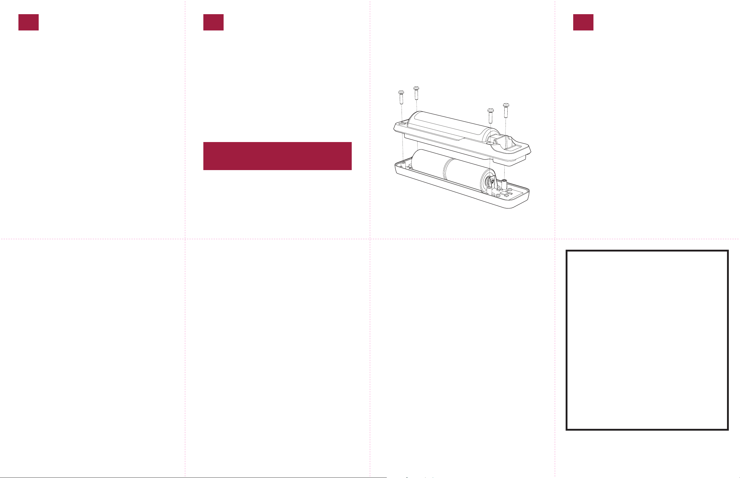
Changing Batteries
The Blackline Beacon’s 2 C Cell batteries expected life is 5 years.
1. Remove the Beacon from the mounting bracket.
2. Remove the 4 screws on the back of the Beacon to remove
the back half of the enclosure to access the batteries as
shown below. Battery orientation is indicated beneath the
batteries on the inside of the front half of the enclosure.
3. Install new batteries and reassemble the Beacon.
IMPORTANT An eective response to an emergency situ-
ation depends upon the accuracy and completeness of this
information.
Changing the transmit power settings
The Blackline Beacon is shipped in the highest transmit power
setting. Transmission power aects the range of the Beacon’s
signal.
To change the transmission power setting
1. Press and hold the button on the Blackline Beacon. The Status
Light will turn On and then turn O. As you continue to hold
the button, the light will begin to blink in sets of ashes that
indicate power levels.
2. Release the button on the set of ashes to program your
desired power level. The status light will repeat the selected
power setting 3 times before returning to normal operating
mode.
The set with the fewest ashes indicates the lowest power
level and the set with the most ashes indicates the highest
power level. The sets will cycle from lowest to highest as you
continue to hold the button.
Information in this document is subject to change without notice. This document is provided “as
is” and Blackline GPS Inc. (“Blackline GPS” or “Blackline”) and its aliated companies and partners
assume no responsibility for any typographical, technical or other inaccura¬cies in this document.
Blackline GPS reserves the right to periodically change information that is contained in this
document. However, Blackline GPS makes no commitment to provide any such changes, updates,
enhancements or other additions to this document to you in a timely manner or at all.
Copyright © 2013 Blackline GPS Inc. All rights reserved.
Except as expressly provided herein, no part of this manual may be reproduced, copied, transmitted, disseminated, downloaded, or stored in any storage medium, for any purpose without the
express prior written consent of Blackline GPS Inc. (“Blackline” or “Blackline GPS”). Blackline GPS
hereby grants permission to download a single copy of this manual onto some form of electronic
storage medium to be viewed and to print one copy of this manual or any revision hereto,
provided that such electronic or printed copy of this manual must contain the complete text of
this copyright notice. Further, any unauthorized commercial distribution of this manual or any
revi¬sion hereto is strictly prohibited.
The Blackline GPS families of related marks, images and symbols, including Loner, Loner IS, Loner
SMD, Loner Mobile, UltimateSense, Protect. Share. Connect. and Blackline GPS are the exclusive
properties and trademarks of Blackline GPS Inc. The BlackBerry and RIM families of related marks,
images and symbols are the exclusive properties and trademarks of Research In Motion Limited.
All other brands, product names, company names, trademarks and service marks are the properties of their respective owners.
Warranty
Your Blackline Beacon is warranted against defects in materials and workmanship for up to one
year from date of purchase. For further details regarding your Blackline GPS warranty, please refer
to your Terms and Conditions of Service.
More Information and Support visit: http://www.blacklinesafety.com for more information.
Declaration of Conformity
Blackline GPS hereby declares that this product incorporating Radio and Telecommunications
Terminal Equipment functionality is in compliance with the essential requirements and other
relevant provisions of Directive 1999/5/EC. A copy of the original Declaration of Conformity is
available at: http://www.blacklinegps.com/ce
FCC Compliance
This equipment has been tested and found to comply with the limits for a Class B digital device,
pursuant to part 15 of the FCC rules. These limits are designed to provide reasonable protection
against harmful interference in a residential instal lation.
Operation is subject to the fol lowing two conditions: (1) This device may not cause harmful
interference, and (2) this device must accept any interference received, including interference
that may cause undesired operation. Changes or modications not expressly approved by the
manufacturer could void the user’s authority to operate the equipment.
This equipment generates, uses and can radiate radio frequency energy and, if not installed and
used in accordance with the instructions, may cause harmful interference to radio communications. However, there is no guarantee that interfer ence will not occur in a particular installation.
If this equipment does cause harmful interference to radio or television reception, which can be
determined by turning the equipment o and on, the user is encouraged to try to correct the
interference by one or more of the following measures:
• Reorient or relocate the receiving antenna.
• Increase the separation between the equipment and receiver.
• Connect the equipment into an outlet on a circuit dierent from that to which the
receiver is connected.
• Consult the dealer or an experienced radio/TV technician for further assistance.
Industry Canada Compliance
This device complies with Industry Canada licence-exempt RSS standard(s). Operation is subject
to the following two conditions: (1) this device may not cause interference, and (2) this device
must accept any interference, including interference that may cause undesired operation of the
device.
Intrinsically Safe
This device is certied Intrinsically Safe for use in Class I, Division
1, Groups A-D and Class II, Division 1, Groups E-G hazardous
(classied) locations.
Specications:
Class I, Division 1, Groups A, B, C, D T4
Class II, Division 1, Groups E, F, G T4
Class I, Zone 0, Group IIC T4
-40*C <= Ta <= +55*C
This product is certied for use with the following batteries:
Duracell PC1400
Energizer LR14DP12
Rayovac ALC-12FP
WARNING: Use only approved batteries.
Consult with your organization’s safety professional for further
information regarding the topic of intrinsic safety and any policies, procedures, facilities, or locations within facilities that may
be related to intrinsic safety.
101332_r1
 Loading...