


BLK-DH3004D
BLK-DH3 Series H.264 960H
4/8/16-Channel DVR User Manual
Products: BLK-DH3004D, BLK-DH3008D, BLK-DH3016D
PLEASE READ THIS MANUAL BEFORE USING YOUR RECORDER, and always follow the
instructions for safety and proper use. Save this manual for future reference.
BLK-DH30xxD_RM
2/21/14
ii
CAUTION
Operate this system only in environments where the temperature and humidity is within the recommended range.
Operation in temperatures or at humidity levels outside the recommended range may cause electric shock and shorten the
life of the product. Refer to the specications for each system component for more information.
LEGAL NOTICE
Observint Technologies (Observint) products are designed to meet safety and performance standards with the use of
specic Observint authorized accessories. Observint disclaims liability associated with the use of non-Obser vint
authorized accessories.
The recording, transmission, or broadcast of any person’s voice without their consent or a court order is strictly
prohibited by law.
Observint makes no representations concerning the legality of certain product applications such as the making,
transmission, or recording of video and/or audio signals of others without their knowledge and/or consent. We
encourage you to check and comply with all applicable local, state, and federal laws and regulations before
engaging in any form of surveillance or any transmission of radio frequencies.
The Black Line is a trademark of Observint Technologies.
Microsoft, Windows, Windows Media, and Internet Explorer are either registered trademarks or trademarks of Microsoft
Corporation in the United States and/or other countries. Android and Google Play are a trademark of Google Inc. Use
of this trademark is subject to Google Permissions. Apple, iPhone, iPod touch, and iPad are registered trademarks of
Apple Inc. Intel and Pentium are trademarks of Intel Corporation in the U.S. and/or other countries.
Other trademarks and trade names may be used in this document to refer to either the entities claiming the marks
and names or their products. Observint disclaims any proprietary interest in trademarks and trade names other than
its own.
No part of this document may be reproduced or distributed in any form or by any means without the express written
permission of Observint.
© 2013, 2014 by Observint Technologies. All Rights Reserved.
11000 N. Mopac Expressway, Building 300, Austin, TX 78759
For Sales and Support, contact your distributor.

iii
960H H.264 DVR User Manual
Table of Contents
SECTION 1 Introduction .......................................................................1
SECTION 2 Hardware Overview and Setup ........................................................2
2.1 Front panel controls and indicators (all models) ..........................................2
2.2 Back panel connectors ................................................................4
2.2.1 BLK-DH3004D ...................................................................4
2.2.2 BLK-DH3008D ...................................................................5
2.2.3 BLK-DH3016D ...................................................................6
2.2.4 RS485, sensor and alarm termination block ..........................................7
2.3 Remote Control ......................................................................8
2.4 DVD-R/W Optical drive installation .....................................................9
2.5 HDD installation ....................................................................12
2.5.1 Installing a 2nd internal HDD .....................................................16
SECTION 3 System Setup ......................................................................18
3.1 Starting the system for the rst time ...................................................18
3.1.1 Entering the SETUP menu ........................................................19
3.2 DISPLAY menu ......................................................................20
3.3 RECORD menu ......................................................................22
3.3.1 Recording Schedules ............................................................23
3.4 DEVICE menu .......................................................................24
3.5 STORAGE menu .....................................................................27
3.6 SYSTEM menu ......................................................................28
3.7 SECURITY menu. . . . . . . . . . . . . . . . . . . . . . . . . . . . . . . . . . . . . . . . . . . . . . . . . . . . . . . . . . . . . . . . . . . . .30
3.8 NETWORK menu ....................................................................33
3.8.1 Network ports .................................................................35
3.9 CONFIG menu ......................................................................35
3.10 QUICK SETUP menu ..................................................................37
SECTION 4 Live, Search, and Playback ...........................................................39
4.1 SEARCH menu ......................................................................41
4.1.1 TIME-LINE search ...............................................................42
4.1.2 EVENT search ..................................................................43
4.1.3 GO TO FIRST TIME search .........................................................43
4.1.4 GO TO LAST TIME search. . . . . . . . . . . . . . . . . . . . . . . . . . . . . . . . . . . . . . . . . . . . . . . . . . . . . . . . . .43
4.1.5 GO TO SPECIFIC TIME search ......................................................44

iv
4.2 ARCHIVE search .....................................................................44
4.2.1 Log search .....................................................................45
4.3 PLAY mode .........................................................................46
4.4 Backup video clip ...................................................................48
SECTION 5 PTZ Control ........................................................................50
SECTION 6 Backup ...........................................................................51
6.1 Still image BACKUP in Live mode ......................................................51
6.2 Still image BACKUP in Playback mode ..................................................51
6.3 Video BACKUP ......................................................................52
6.4 BACKUP still images or video from the ARCHIVE list ......................................53
6.5 Playing backed up video clips .........................................................54
SECTION 7 Remote Client Software .............................................................56
7.1 PC Requirements ....................................................................56
7.2 Installing the Remote Client ..........................................................56
7.3 Remote Client initial display ..........................................................57
7.4 Setup .............................................................................59
7.4.1 General Setup ..................................................................59
7.4.2 Site Setup .....................................................................60
7.4.3 Event Setup ....................................................................62
7.4.4 Event Search Setup .............................................................62
7.4.5 Record Setup ..................................................................63
7.4.6 Record Disk Setup ..............................................................64
7.4.7 Display Setup ..................................................................64
7.5 Connecting to a DVR .................................................................65
7.5.1 Bidirectional Audio .............................................................65
7.6 Remote Search mode and functions ...................................................66
7.6.1 Searching for and playing video recorded by the DVR ................................67
7.6.2 Backing up video from the DVR on the Remote Client PC ..............................68
7.6.3 Image capture .................................................................70
SECTION 8 Multi Client Software ..............................................................71
8.1 PC Requirements ....................................................................71
8.2 Installing the Multi Client ............................................................71
8.3 Multi Client initial display ............................................................72
8.3.1 Using Net Finder ................................................................74
8.3.2 Event List ......................................................................76
TABLE OF CONTENTS

v
960H H.264 DVR User Manual
8.4 Setup .............................................................................76
8.4.1 General Setup ..................................................................76
8.4.2 Event Setup ....................................................................77
8.4.3 Event Search Setup .............................................................77
8.4.4 Record Setup ..................................................................78
8.4.5 Record Disk Setup ..............................................................79
8.4.6 Display Setup ..................................................................79
8.4.7 About Setup ...................................................................80
8.5 Connecting to a DVR .................................................................80
8.5.1 Bidirectional Audio .............................................................81
8.5.2 Capture .......................................................................81
8.5.3 Record ........................................................................82
8.6 Remote playback and backup .........................................................82
8.6.1 Remote playback ...............................................................82
8.6.2 Backing up video from the DVR on the Multi Client PC ................................85
8.7 Local playback ......................................................................86
8.7.1 AVI backup during playback .....................................................88
SECTION 9 WebViewer ........................................................................90
9.1 Connecting to the DVR with Firefox®, Chrome™ or Safari ..................................90
9.2 Using WebViewer ...................................................................93
9.3 Setup .............................................................................96
9.3.1 Setup DISPLAY .................................................................96
9.3.2 Setup RECORD. . . . . . . . . . . . . . . . . . . . . . . . . . . . . . . . . . . . . . . . . . . . . . . . . . . . . . . . . . . . . . . . . .97
9.3.3 Setup DEVICE ..................................................................97
9.3.4 Setup STORAGE .................................................................99
9.3.5 Setup SYSTEM ..................................................................99
9.3.6 Setup SECURITY ...............................................................100
9.3.7 Setup NETWORK ...............................................................101
9.3.8 Setup UPGRADE ...............................................................102
9.3.9 Setup INFORMATION ...........................................................102
9.4 DVR Search. . . . . . . . . . . . . . . . . . . . . . . . . . . . . . . . . . . . . . . . . . . . . . . . . . . . . . . . . . . . . . . . . . . . . . . .102
9.4.1 Playing recorded video .........................................................104
9.5 Backup recorded video ..............................................................105
9.5.1 Capture ......................................................................105
SECTION 10 Blackhawk for Mac™ .........................................................................107
TABLE OF CONTENTS

vi
10.1 Getting started ....................................................................107
10.1.1 Finding the DVR network settings ................................................107
10.1.2 Finding your Apple® Mac™ network settings .......................................108
10.1.3 Connecting to your DVR ........................................................109
10.2 Installing and starting BlackHawk for MAC .............................................109
10.2.1 Connecting to your DVR ........................................................110
10.3 Live window ......................................................................110
10.3.1 Using Site Entry registration .....................................................112
10.4 Closing the application .............................................................113
10.5 Search and Playback Video ..........................................................113
10.6 Search for and playback video .......................................................116
SECTION 11 BLACKHAWK Mobile Phone Apps ....................................................117
11.1 BLACKHAWK for iPhone .............................................................117
11.1.1 Installing BLACKHAWK .........................................................117
11.1.2 Live viewing ..................................................................117
11.1.3 PTZ Control ...................................................................119
11.1.4 Playback .....................................................................119
11.2 BlackHawk for Android™ ............................................................120
11.2.1 Installing BlackHawk ...........................................................121
11.2.2 Live .........................................................................121
11.2.3 PTZ Control ...................................................................122
11.2.4 Playback .....................................................................122
11.2.5 Screen Shot and Viewer .........................................................124
SECTION 12 Specications ....................................................................125
APPENDIX A DVR Compatible Hard Disk Drives ....................................................127
APPENDIX B Estimated Storage Capacity. . . . . . . . . . . . . . . . . . . . . . . . . . . . . . . . . . . . . . . . . . . . . . . . . . . . . . . . . 130
APPENDIX C Device Log .......................................................................131
APPENDIX D DDNS setup with obsddnscenter.com ................................................132
APPENDIX E DVR Setup Menu Components ......................................................136

1
960H H.264 DVR User Manual
SECTION 1: INTRODUCTION
SECTION 1
Introduction
Features
• H.264 video compression
• HDMI 1080p Video Output
• QUADPLEX: Simultaneous live or playback while recording, network transfer, and backup
• USB 2.0 port for backup, rmware upgrade, conguration export/import, or USB mouse
• Individual channel operation such as FPS, quality, recording mode, & detection zone
• Various network access: network client SW, web viewer, smart phone APP, and CMS
• Remote setup and remote upgrade
• Remote access via PC, MAC®, or smart phones
• Recording by schedule, continuous, alarm, motion, or continuous
• Free DDNS server
• Bandwidth control
• E-mail event notication
• NTP (Network Time Protocol)
• Watermark
• Synchronized audio
• Bi-directional audio
• Time stamp over backup data
• Easy and various data backup via DVD, USB ash drive, USB external HDD, and network
• HDD S.M.A.R.T. status check and alert via e-mail or internal beep
• USB mouse, IR remote control
• Multi OSD languages
• AVI backup
• Network Access via WebViewer (embedded browser-based client), UMS Client (for monitoring a single DVR), Multi Client (for
monitoring multiple DVRs concurrently), and smartphone apps for Apple® iPhone® and Android™.
Your DVR includes:
• DVR with DVD-R/W drive and hard disk drive (HDD)
• Software CD containing the UMS Client, Multi Client, and the DVR user manual (this document)
• Remote Control
• Power Adaptor (12 Vdc, 5A) and cable
• Mouse
• Brackets, screws and cables for HDD and DVR (2 sets)
• Quick Start Guide document
2
SECTION 2: HARDWARE OVERVIEW AND SETUP
SECTION 2
Hardware Overview and Setup
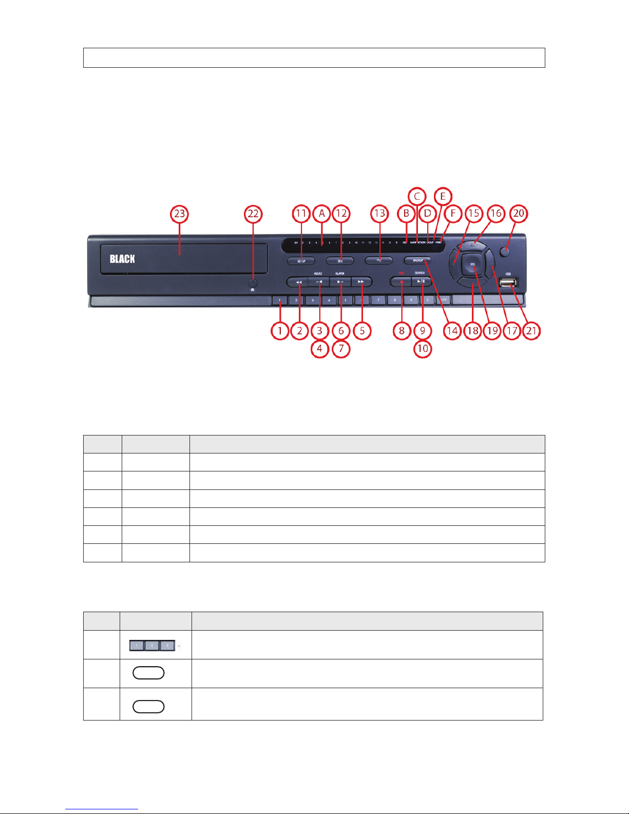
2.1 Front panel controls and indicators (all models)
4/8/16 Channel DVR Front Panel
Table 1. Front Panel LED Indicators
No. Name Description
A C H1~1 6
Indicates that the channel is b eing recorded.
B HDD Indicates that the system is accessing the hard disk .
C ALARM Indicates when a sensor is triggered or motion is detec ted.
D NETWORK Indicates that a net work client is connec ted.
E BACKUP Indicates that a USB or DVD -R/W stor age device is storing images or vide o.
F POWER Indicate s that the system is sw itched on.
Table 2. Front Panel Buttons
No. Name Description
1
Channel keys. For chann el 10, press the 0 key. For channel 11, press the +10 and 1 key. For channel 16, press the +10
and 6 key.
2
Press to rewind the vid eo in playback mode.
3
..
AUDIO
Press to selec t audio mode such as SINGLE (highlighte d channel), MIX (combin e all channels), or MUTE (all c hannels).

3
960H H.264 DVR User Manual
SECTION 2: HARDWARE OVERVIEW AND SETUP
No. Name Description
4
..
AUDIO
Jump/step back ward. In playback mode, the play back position moves 60 seconds backward.
5
Press to fast forward the recording in playback mode.
6
..
ALARM
Press to enable/disable ALARM operation.
7
..
ALARM
Jump/Step forward. In p layback mode, t he playback position moves 6 0 seconds for ward.
8
REC
Press to star t or stop manual recording.
9
/ ll
SEARCH
Press to open th e SEARCH menu in live display mode.
10
/ ll
SEARCH
Press to play/pause the recording in playb ack mode.
11
SETUP
Press to enter SETUP menu.
12
SEQ
Enable/disable the automatic sequence display of channels in f ull screen, quad-split, and 9-split display mode.
13
PTZ
Press to contro l Pan/Tilt/ Zoom operations.
14
BACKUP
Press to capture live or playback mode v ideo in JPEG format.
15
t (LEFT)
Press to move lef t or to change the value s in Setup mode. When entering a p assword, it inser ts a 4.
16
p (UP)
Press to move up th e menu in Setup mode. When entering a password, it insert s a 1.
17
u (RIGHT)
Press to move right or to change the values in Setup mode. When entering a p assword, it inserts a 2.
18
q (DOWN)
Press to move down the menu in Setup mode. When entering a p assword, it inser ts a 3.
19
SEL
Press to selec t desired menu item or to store the setup valu e.
20
ESC
Press f or temporar y storage of the changed value or to return to the previous menu scre en.
21 USB Port
Use with a USB ash drive to archive s till images and v ideos, and upgrade r mware, or use to connec t a USB mouse to
the DVR.
22
To open and close the inser t tray, press the button
23 DVD Drive To save vide o, insert a CD-R/DV D-R
4
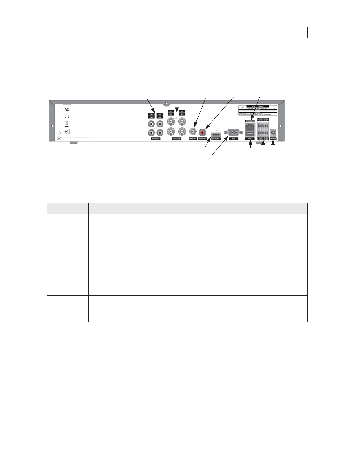
2.2 Back panel connectors
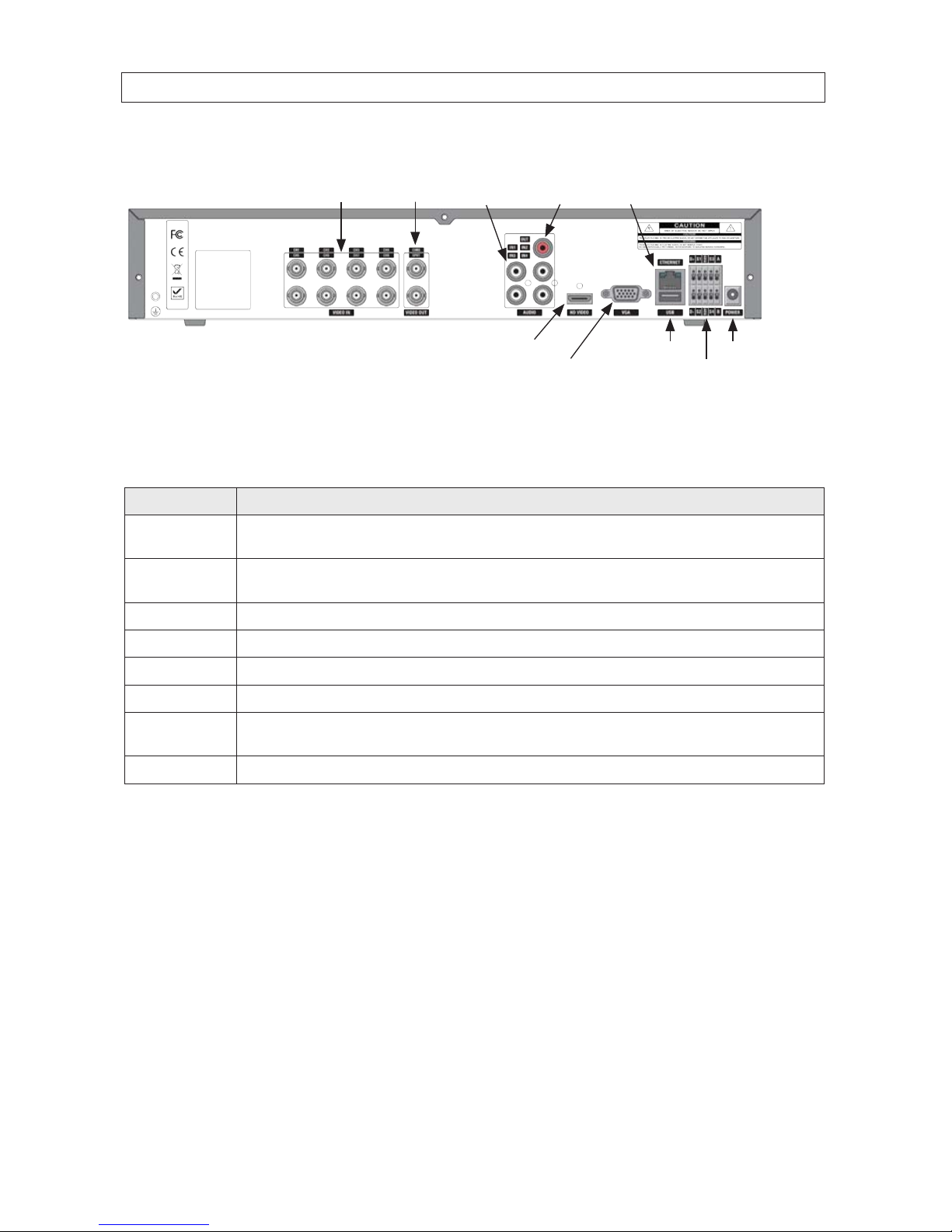
2.2.1 BLK-DH3004D
CVBS Out Ethernet (RJ-45)Audio In Video In
USB connector
RS-485, sensor and alarm terminations
Audio Out
VGA monitor out
Power connectorHD VIDEO
4-Channel DVR Rear Panel
Table 3. BLK-DH3004D Rear Panel Connectors
Name Description
AUDIO IN 4 RCA connectors for audio input
VIDEO IN 4 BNC connectors for compo site video input
CVBS Composite video output
AUDIO OUT 1 RCA connector for audio ou tput
ETHERNET
RJ-45 connector for LAN connection.
HD VIDEO Connec tor for an HDMI monitor.
VGA Connec tor for a VGA monitor.
USB Use with a USB ash drive to archive s till images and videos, and upgrade rmware, or use to connec t a USB mouse to the DVR
RS-485, sensor and
alarm terminations
See description b elow.
POWER connector Connec t DC12V 5A power adaptor
SECTION 2: HARDWARE OVERVIEW AND SETUP
5
960H H.264 DVR User Manual
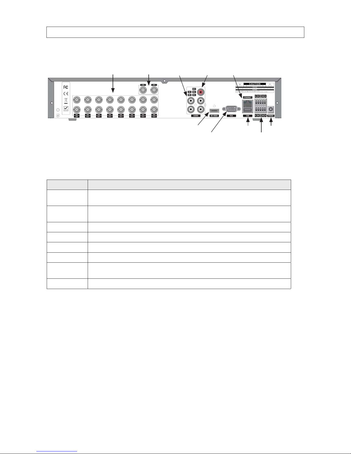
2.2.2 BLK-DH3008D
CVBS Out
Ethernet (RJ-45)
Audio InVideo In
USB connector
RS-485, sensor and alarm terminations
Audio Out
VGA monitor out
Power connectorHD VIDEO
8-Channel DVR Rear Panel
Table 4. BLK-DH3008D Rear Panel Connectors
Name Description
VIDEO IN
CVBS, SPOT
8 BNC connectors for compo site video input
CVBS and SPOT comp osite video output
AUDIO IN
AUDIO OUT
4 RCA connectors for audio input
1 RCA connector for audio ou tput
HD VIDEO
Connec tor for an HDMI monitor.
VGA Connec tor for a VGA monitor.
ETHERNET RJ-45 connector for LAN connection.
USB Use with a USB ash drive to archive s till images and videos, and upgrade rmware, or use to connec t a USB mouse to the DVR
RS-485, sensor and
alarm terminations
See description b elow.
POWER connector Connec t DC12V 5A power adaptor
SECTION 2: HARDWARE OVERVIEW AND SETUP
6
2.2.3 BLK-DH3016D
CVBS, SPOT Out
Ethernet (RJ-45)
Audio InVideo In
USB connector
RS-485, sensor and alarm terminations
Audio Out
VGA monitor out
Power connectorHD VIDEO
16-Channel DVR Rear Panel
Table 5. BLK-DH3016D Rear Panel Connectors
Name Description
VIDEO IN
CVBS, SPOT
16 BNC conne ctors for composite video inpu t
CVBS and SPOT comp osite video output
AUDIO IN
AUDIO OUT
4 RCA connectors for audio input
1 RCA connector for audio ou tput
HD VIDEO
Connector for an HDMI monitor.
VGA Connec tor for a VGA monitor.
ETHERNET RJ-45 connector for LAN connection.
USB Use with a USB ash drive to archive s till images and v ideos, and upgrade r mware, or use to connec t a USB mouse to the DVR
RS-485, sensor and
alarm terminations
See description b elow.
POWER connector Connec t DC12V 5A power adaptor
SECTION 2: HARDWARE OVERVIEW AND SETUP
7
960H H.264 DVR User Manual
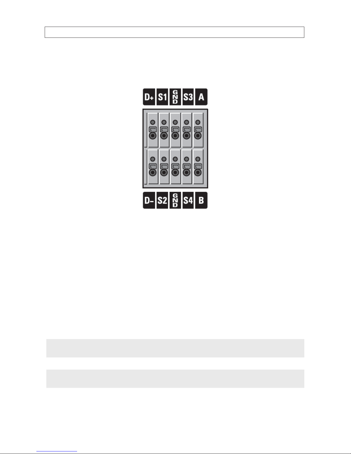
2.2.4 RS485, sensor and alarm termination block
Use the back panel termination block to connect sensor, RS-485, and alarm out cables.
Pin block denitions:
D+, D-: RS-485 D+ and RS-485 D-
S1, GND: Sensor 1 input
S2, GND: Sensor 2 input
S3, GND: Sensor 3 input
S4, GND: Sensor 4 input
A, B: Alarm output
NOTE
S1 - S4 sensor inputs can be normally open (N.O.) or normally closed (N.C.). To congure the sensor type, go to
SETUP -> Device -> Sensor: Type.
NOTE
A - B (alarm out) can be triggered by any single of combination of sensors and motion on or video loss in up to four camera
channels. To congure alarm causing conditions, go to: SETUP -> Device -> Alarm Out.
SECTION 2: HARDWARE OVERVIEW AND SETUP
8
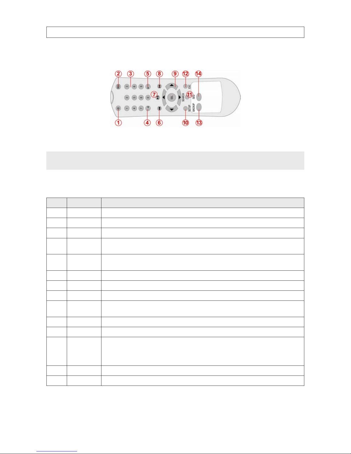
2.3 Remote Control
Typical Remote Control
NOTE
The remote control provided with your DVR may appear dierent from the one shown above. However, the buttons function as
described in the table below.
Table 6. Remote Control Button Functions
No. Name Function
1 ID
When a remote cont rol ID number is se tup in DVR, press this bu tton before the number.
2 REC To start and sto p manual recording.
3 0 .. 9 To select channel (1, 2, 3, ..) or to enter a DVR ID number.
4 F/RE W
During Playback – To move the p layback position 60 secon ds back.
During Pause – To move the playback position 1 frame back.
5 F/ADV
During Playback – To move the p layback position 60 secon ds forward.
During Pause – To move the playback position moves 1 frame for ward.
6 REW To rew ind the recording. Pre ss again to increase the rewind speed.
7 PL AY/PA USE To play or to p ause the recording in playbac k mode.
8 FF To fast for ward the recording. Press again to incr ease the fast forward speed.
9
Direction
Buttons
Press to move to menu items or select a channel.
10 SETUP To open t he SETUP menu.
11 SEARCH To go to the SEARCH menu.
12 ESC
During setup – To return to the previous menu screen.
During playback – To exit p layback mode
System lock – To lock a s ystem when pressin g ESC
button for 5 s econds.
System unlock – To unlock a sy stem when pressing ESC
button for 5 s econds.
13 BACKUP To start a backup operations in live or playback m ode.
14 SEQ To start auto se quencing the s creen in full screen mode. ( Toggle)
SECTION 2: HARDWARE OVERVIEW AND SETUP
9
960H H.264 DVR User Manual
2.4 DVD-R/W Optical drive installation
If your DVR does not include an internal DVD-R/W drive, use the following procedure to install one. The DVD-R/W can be used to
archive stored data including video clips and snapshots. Your DVR will accommodate one standard-size desktop system DVD-R/W
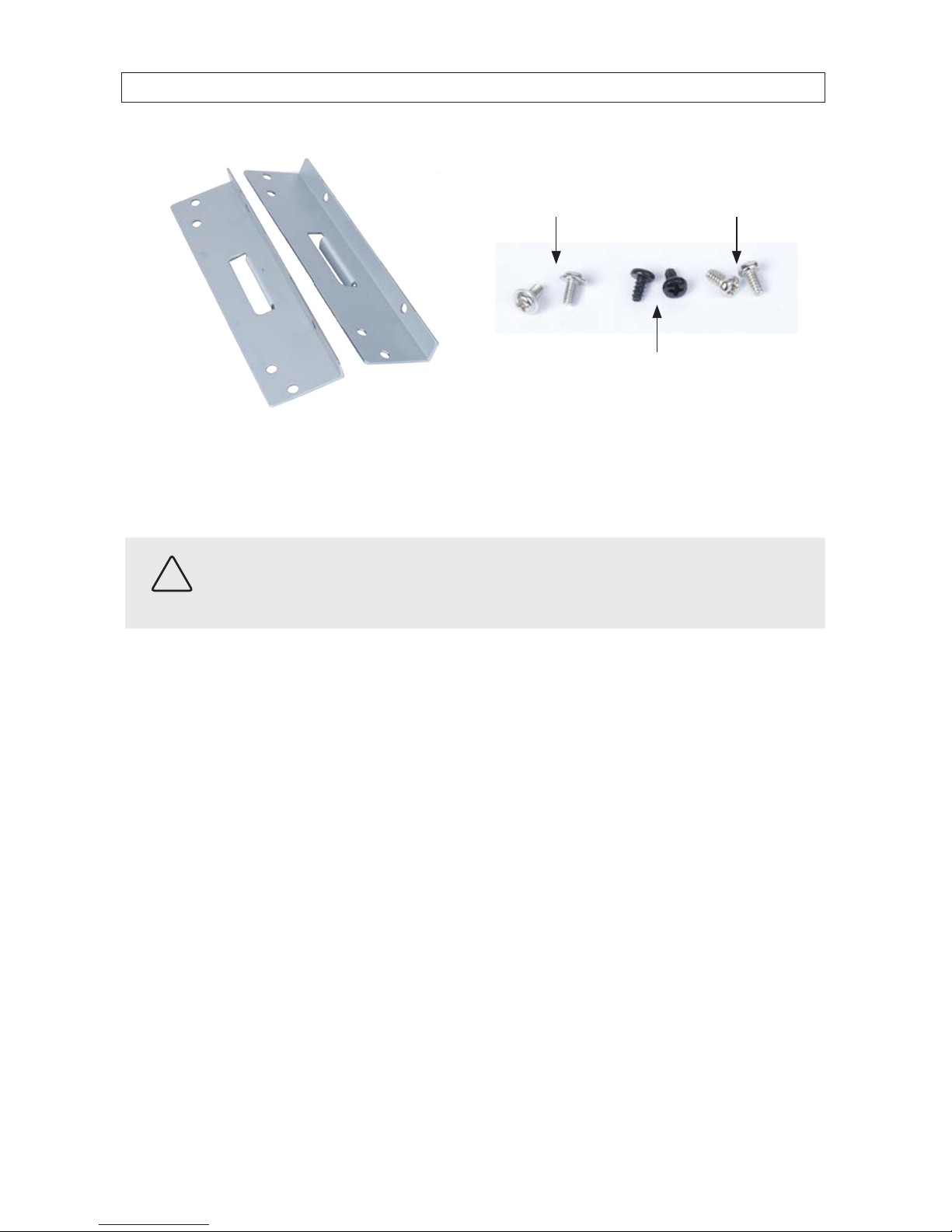
drive with a serial-ATA (SATA) interface. If your DVR was purchased without a DVD-R/W drive or HDD drive, a hardware kit,
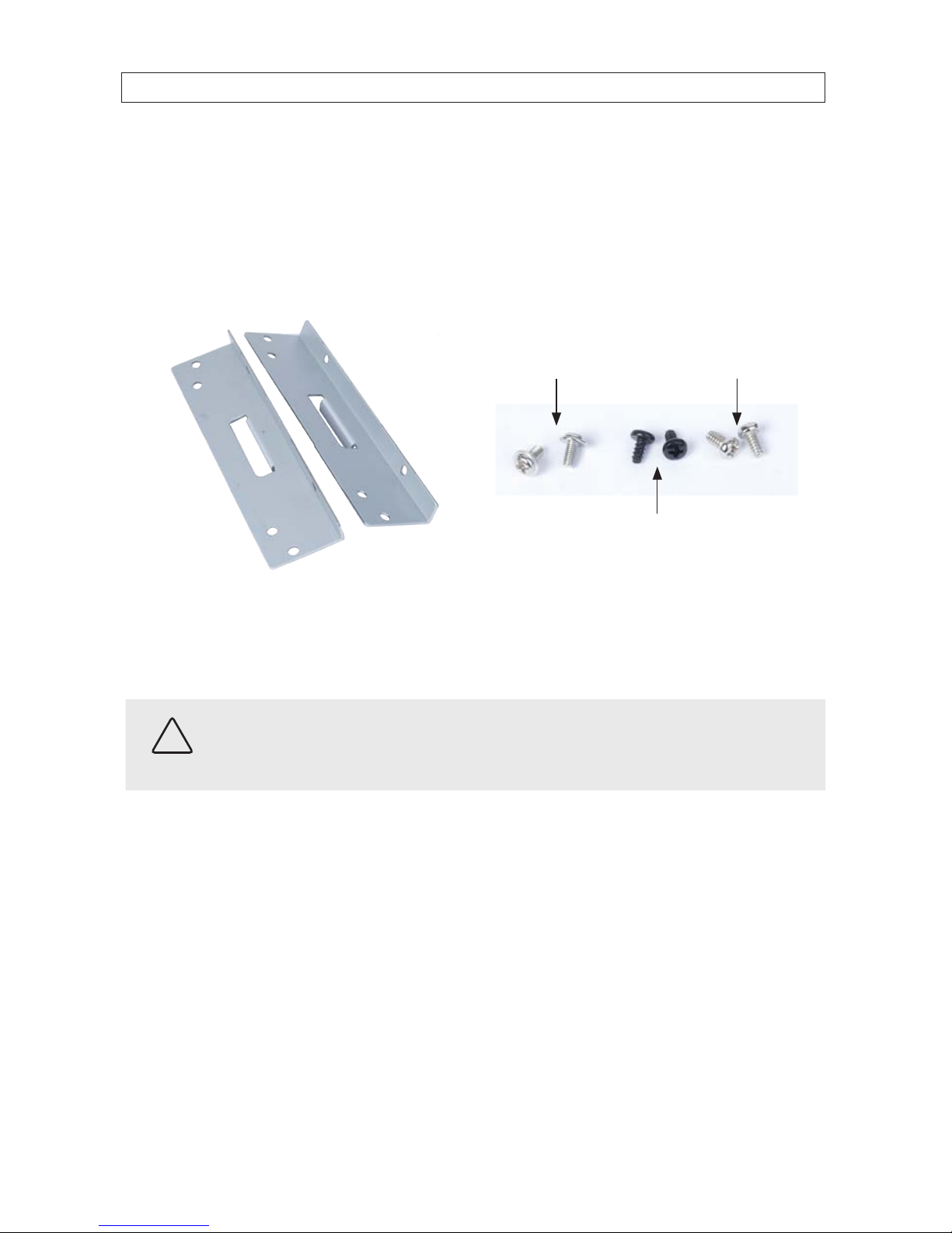
including mounting brackets, screws and cables is included with the DVR.
For attaching bracket
to DVD-R/W (at-head,
ne-thread screws (4))
For attaching bracket to
HDD (pan-head, medium-
thread screws (4))
For attaching bracket
to chassis (pan-head,
course-thread screws)
Mounting brackets (one pair per drive) Screw types
To install a DVD-RW drive, carefully follow the procedure below. Although this procedure is illustrated for a 16-channel DVR, it is
identical for the 4- and 8-channel DVR.
CAUTION
Follow recommended electrostatic discharge (ESD) guidelines while performing this procedure. Install the DVD-R/W drive in
a static-free environment, wearing a certied ESD wrist strap. If a static free environment and ESD wrist strap is not available,
touch the bare metal of the DVR chassis frequently when installing the drive to dissipate the static charge naturally generated
on your skin and clothing.
1. If your DVR is powered on, use the menu system to perform a System Shutdown.
a. Right click anywhere on the live view screen, then click SYSTEM SHUTDOWN in the pop-up menu (see “3.1 Starting
the system for the rst time” on page 18), or click the SYSTEM SHUTDOWN icon on the taskbar.
b. Follow the on-screen instructions for shutting down the system.
2. Disconnect the power adapter from the back of the DVR.
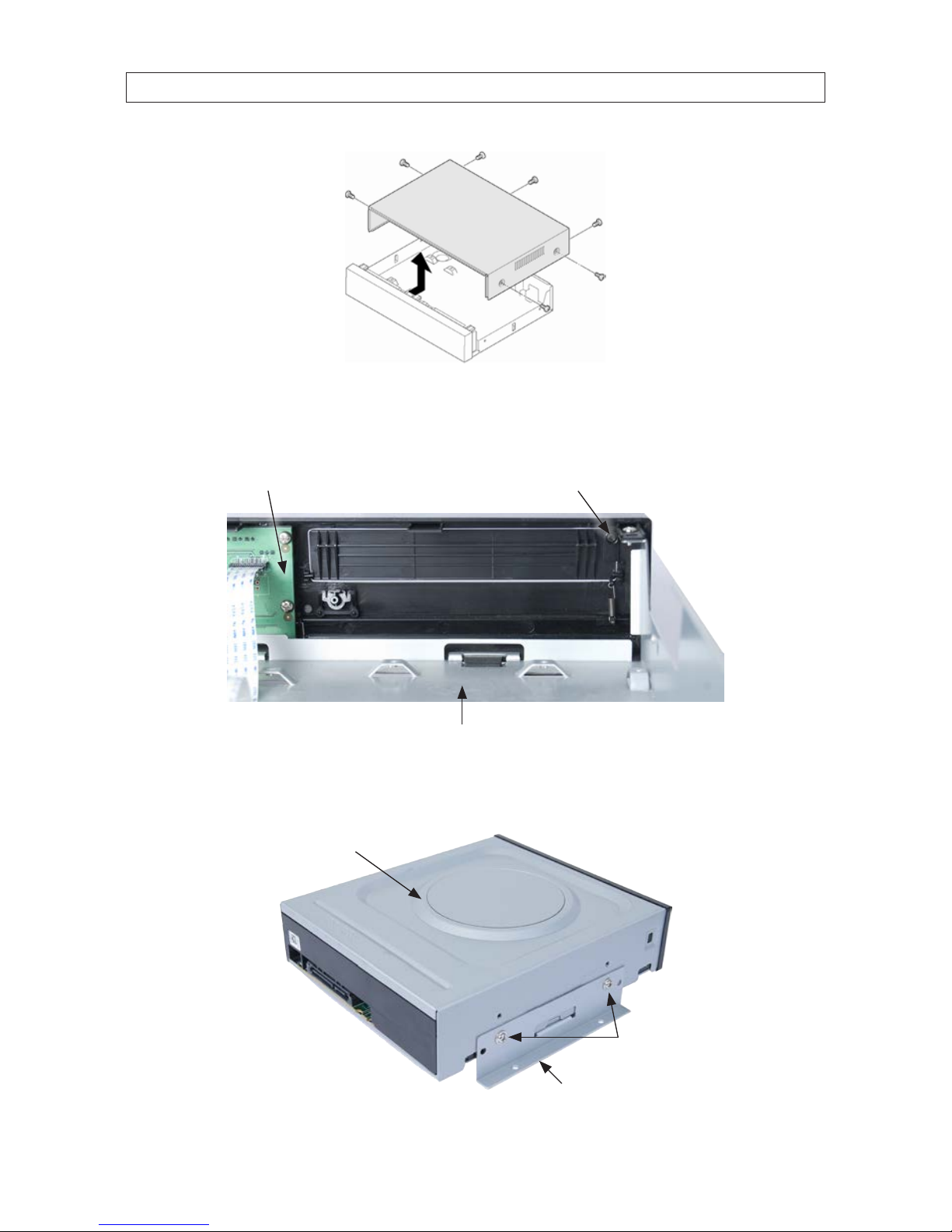
3. Remove the top cover from the DVR by removing the three cover screws on the back of the chassis, and the two on each side.
See the drawing below.
SECTION 2: HARDWARE OVERVIEW AND SETUP
10
4. Remove the optical drive tray door retain screw from the inside of the DVR front panel. See the picture below. Use a #1
Phillips screwdriver.
Optical drive tray door
retaining screw
Back side of
DVR front panel
Optical drive bay
5. Attach a mounting bracket to each side of the DVD-R/W drive as shown below using the at-head ne thread screws
provided. Use two screws for each bracket. Tighten the screws until snug.
DVD-R/W drive
Mounting bracket
Flat-head ne-thread
screws (2)
SECTION 2: HARDWARE OVERVIEW AND SETUP
11
960H H.264 DVR User Manual
SECTION 2: HARDWARE OVERVIEW AND SETUP
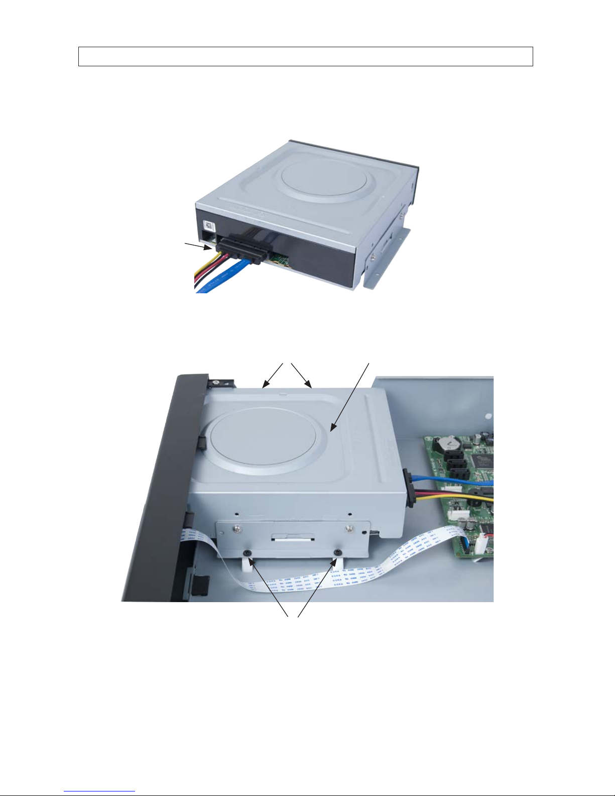
6. Plug a SATA data and power cable assembly into the mating connectors on the back of the DVD-R/W drive. Ensure the
connector is fully seated.
SATA data and
power cable
7. Position the DVD-R/W drive in the optical drive bay as shown below. Secure the drive to the chassis with four screws through
the mounting brackets, two on each side. Use black pan-head course-thread screws provided. Tighten the screws until snug.
DVD-R/W drive in optical drive bayScrews
Screws
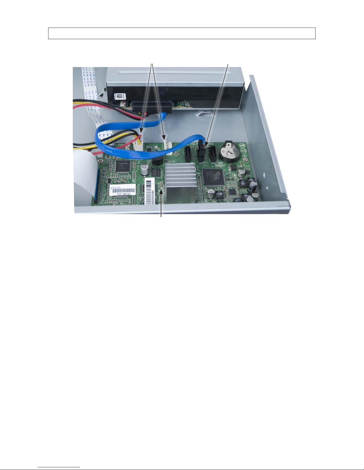
8. Plug the SATA data cable (blue cable) into the SATA1 connector on the PC board, then plug the SATA power cable into one of
the SATA power connectors on the PC board.
12
SECTION 2: HARDWARE OVERVIEW AND SETUP
SATA1 connector
SATA power connectors
PC board
Ensure that the data and power cable connectors are fully seated onto the connectors on the PC board.
9. Reinstall the DVR cover using the 7 screws removed earlier.
10. Reattach the power adapter to the back of the DVR.
2.5 HDD installation
The HDD is used to store video and snapshots recorded by the DVR. Normally, DVRs have one internal HDD and one internal
DVD-R/W drive. However, a second internal HDD can be installed in place of the DVD drive, if needed.
Your DVR will accommodate one standard-size desktop system HDD with a SATA interface. When choosing an HDD to install, select
one from the list provided in “APPENDIX A DVR Compatible Hard Disk Drives” on page 127 to ensure the best performance. If your
DVR was purchased without an HDD, a hardware kit, including mounting brackets, screws and cables is included with the DVR.
13
960H H.264 DVR User Manual
SECTION 2: HARDWARE OVERVIEW AND SETUP
For attaching bracket
to DVD-R/W (at-head,
ne-thread screws (4))
For attaching bracket to
HDD (pan-head, medium-
thread screws (4))
For attaching bracket
to chassis (pan-head,
course-thread screws)
Mounting Brackets (one pair per drive) Screw types
To install an HDD, carefully follow the procedure below. Although this procedure is illustrated for a 16-channel DVR, it is identical for
a 4- or 8-channel DVR.
CAUTION
Follow recommended electrostatic discharge (ESD) guidelines while performing this procedure. Install the HDD in a static-free
environment, wearing a certied ESD wrist strap. If a static free environment and ESD wrist strap is not available, touch the bare
metal of the DVR chassis frequently when installing the drive to dissipate the static charge naturally generated on your skin and
clothing.
1. If your DVR is powered on, use the menu system to perform a System Shutdown.
a. Right click anywhere on the live view screen, then click SYSTEM SHUTDOWN in the pop-up menu (see “3.1 Starting
the system for the rst time” on page 18), or click the SYSTEM SHUTDOWN icon on the task bar.
b. Follow the on-screen instructions for shutting down the system.
2. Disconnect the power adapter from the back of the DVR.
3. Remove the top cover from the DVR by removing the three cover screws on the back of the chassis, and the two on each side.
See the drawing below.
14
SECTION 2: HARDWARE OVERVIEW AND SETUP
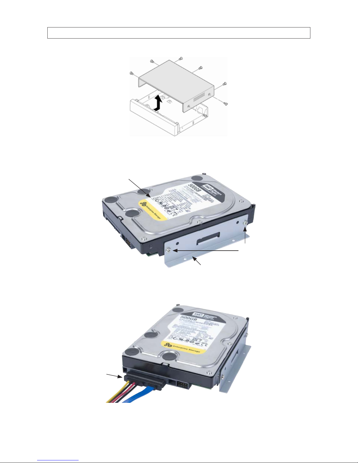
4. Attach a mounting bracket to each side of the HDD as shown below using the pan-head medium- thread screws provided.
Use two screws for each bracket. Tighten the screws until snug.
HDD
Mounting bracket
Pan-head mediumthread screws (2)
5. Plug a SATA data and power cable assembly into the mating connectors on the back of the HDD. Ensure the connector is fully
seated.
SATA data and
power cable
15
960H H.264 DVR User Manual
SECTION 2: HARDWARE OVERVIEW AND SETUP
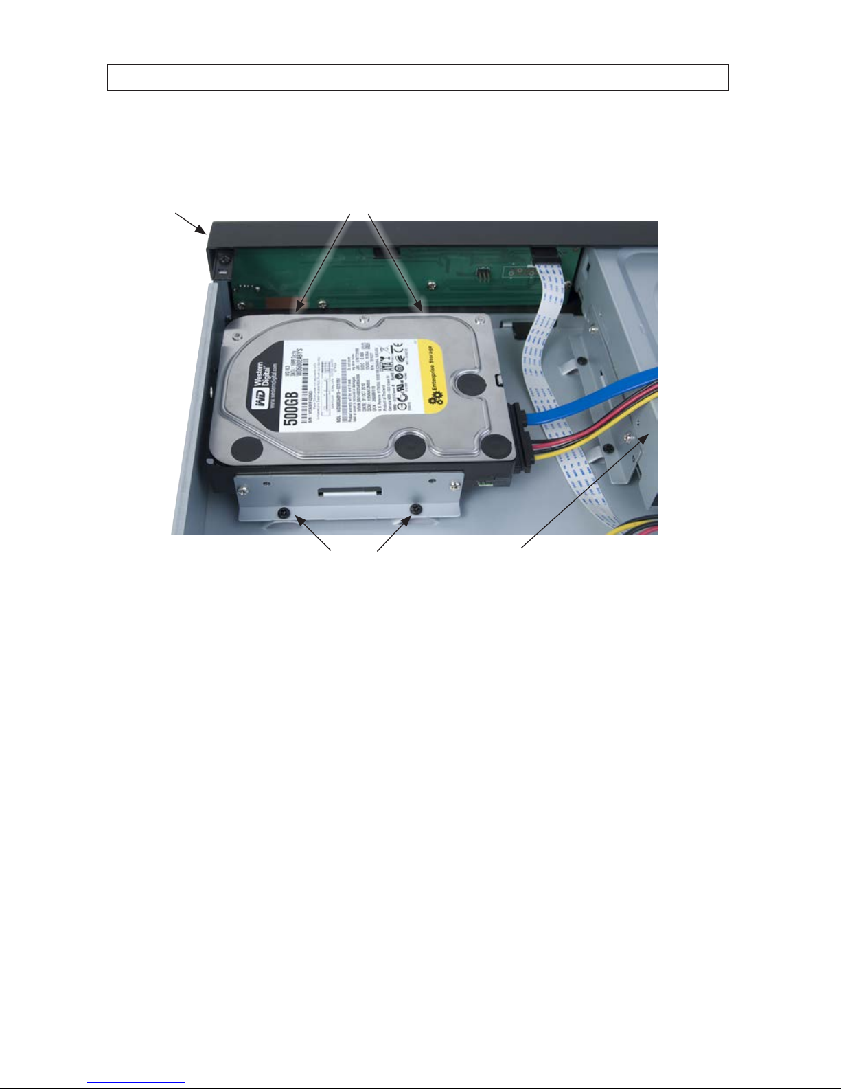
6. Position the HDD into the HDD bay as shown below. Secure the drive to the chassis with four screws through the mounting
brackets, two on each side of the HDD. Use black pan-head course-thread screws provided. Tighten the screws until snug.
Screws (2) between HDD and
back of DVR front panel
Screws
DVR front panel
DVD-R/W drive
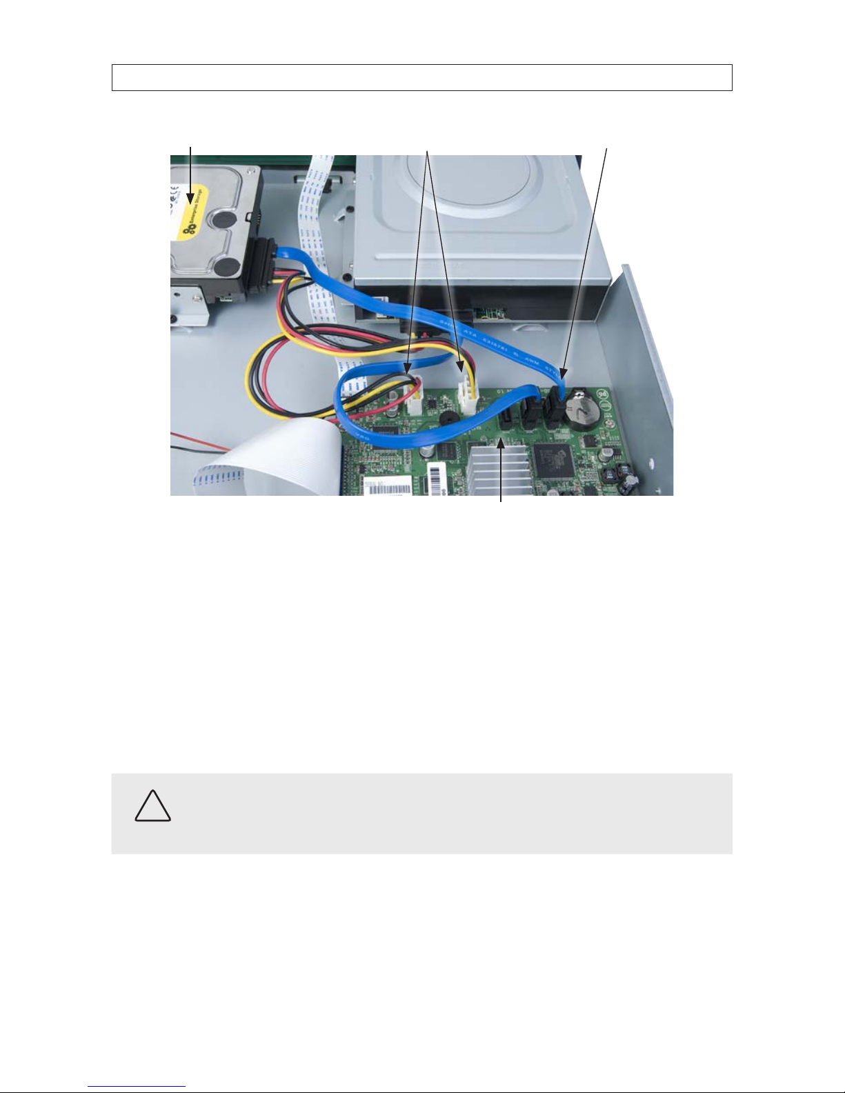
7. Plug the SATA data cable (blue cable) into the SATA0 connector on the PC board, then plug the SATA power cable into one of
the SATA power connectors on the PC board.
16
SECTION 2: HARDWARE OVERVIEW AND SETUP
SATA0 connectorSATA power connectors
PC board
HDD
Ensure that the data and power cable connectors are fully seated onto the connectors on the PC board.
8. Reinstall the DVR cover using the 7 screws removed earlier.
9. Reattach the power adapter to the back of the DVR.
2.5.1 Installing a 2nd internal HDD
The DVR can include two internal HDDs, with the second HDD installed in the DVD-R/W (optical) drive bay. To install a 2nd HDD, do
the following.
CAUTION
Follow recommended electrostatic discharge (ESD) guidelines while performing this procedure. Install the HDD in a static-free
environment, wearing a certied ESD wrist strap. If a static free environment and ESD wrist strap is not available, touch the bare
metal of the DVR chassis frequently when installing the drive to dissipate the static charge naturally generated on your skin and
clothing.
1. If a DVD-RW drive is installed in the optical drive bay, remove it by reversing the procedure included above in “2.4 DVD-R/W
Optical drive installation” on page 9.
2. Attach the mounting brackets and data/power cable to the 2nd HDD. See “2.5 HDD installation” on page 12 above.
17
960H H.264 DVR User Manual
SECTION 2: HARDWARE OVERVIEW AND SETUP
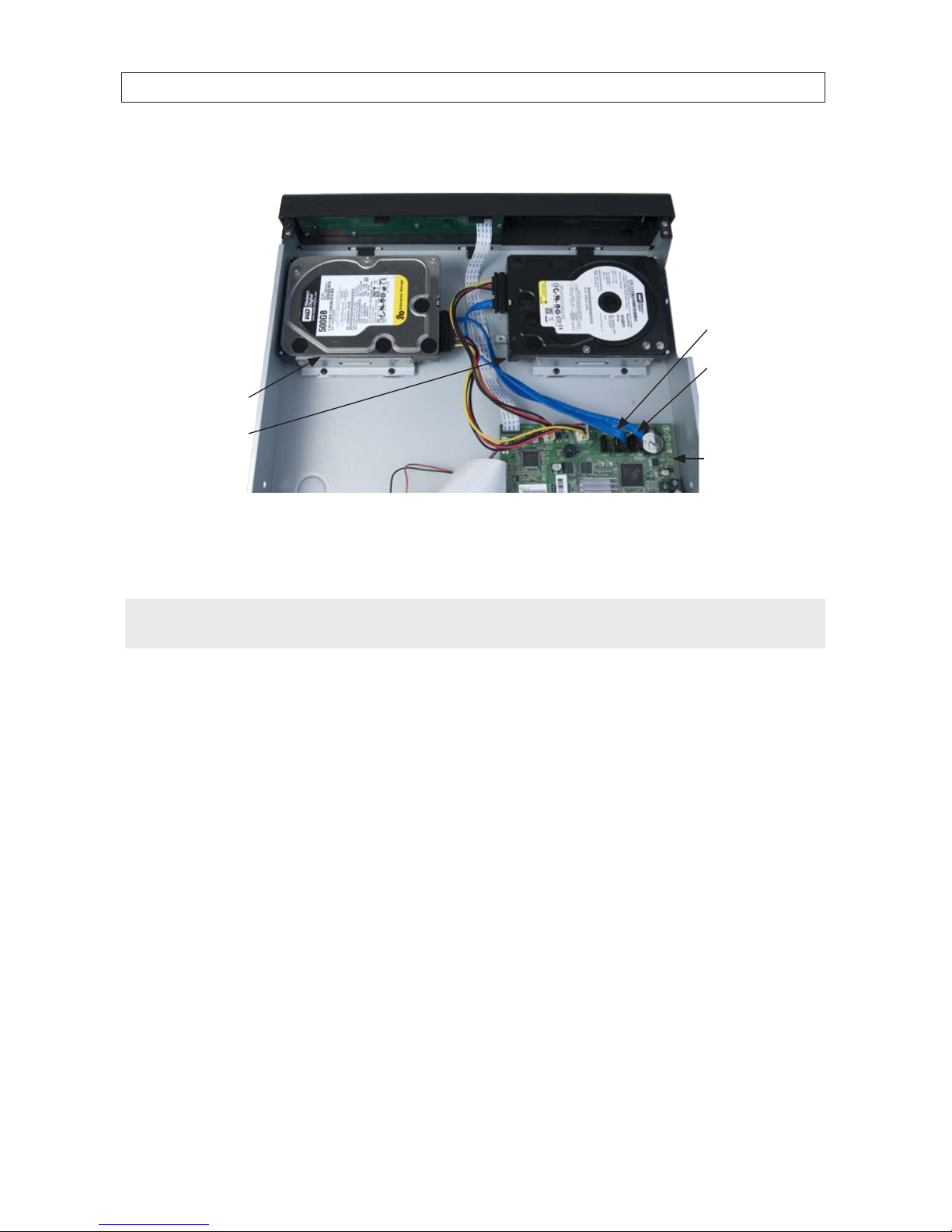
3. Position the HDD in the optical bay as shown below, and attach it to the chassis using 4 screws, 2 on each side.
SATA1 connector
SATA0 connector
Primary HDD
Secondary HDD
PC board
4. Connect the HDD SATA data cable (blue) to the SATA1 connector on the PC board.
5. Connect the HDD SATA power cable to one of the mating connectors on the PC board.
NOTE
In a DVR with 2 HDDs, the primary HDD is connected to the SATA0 connector and the secondary HDD is connected to the SATA1
connector.
18
SECTION 3: SYSTEM SETUP
SECTION 3
System Setup
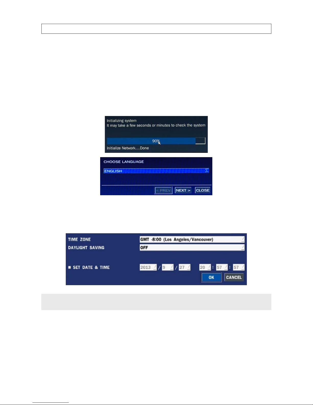
3.1 Starting the system for the rst time
When booting the system for the rst time, the following messages appear. After the initialization sequence completes, select your
preferred language and set the date and time.
When the Set date and time window opens, use the drop down lists to select the TIME ZONE and DAYLIGHT SAVINGS time
preference. Check the box show set the current cate and time, if needed, then click Finish. The date and time setting is used to
timestamp recordings.
NOTE
If the DVR will be networked with access to the internet, you can congure an it to automatically acquire date and time settings
from an NTP (network time protocol) server. See the System conguration settings later in this manual.
19
960H H.264 DVR User Manual
SECTION 3: SYSTEM SETUP
Typical System Desktop Display With One Camera Active
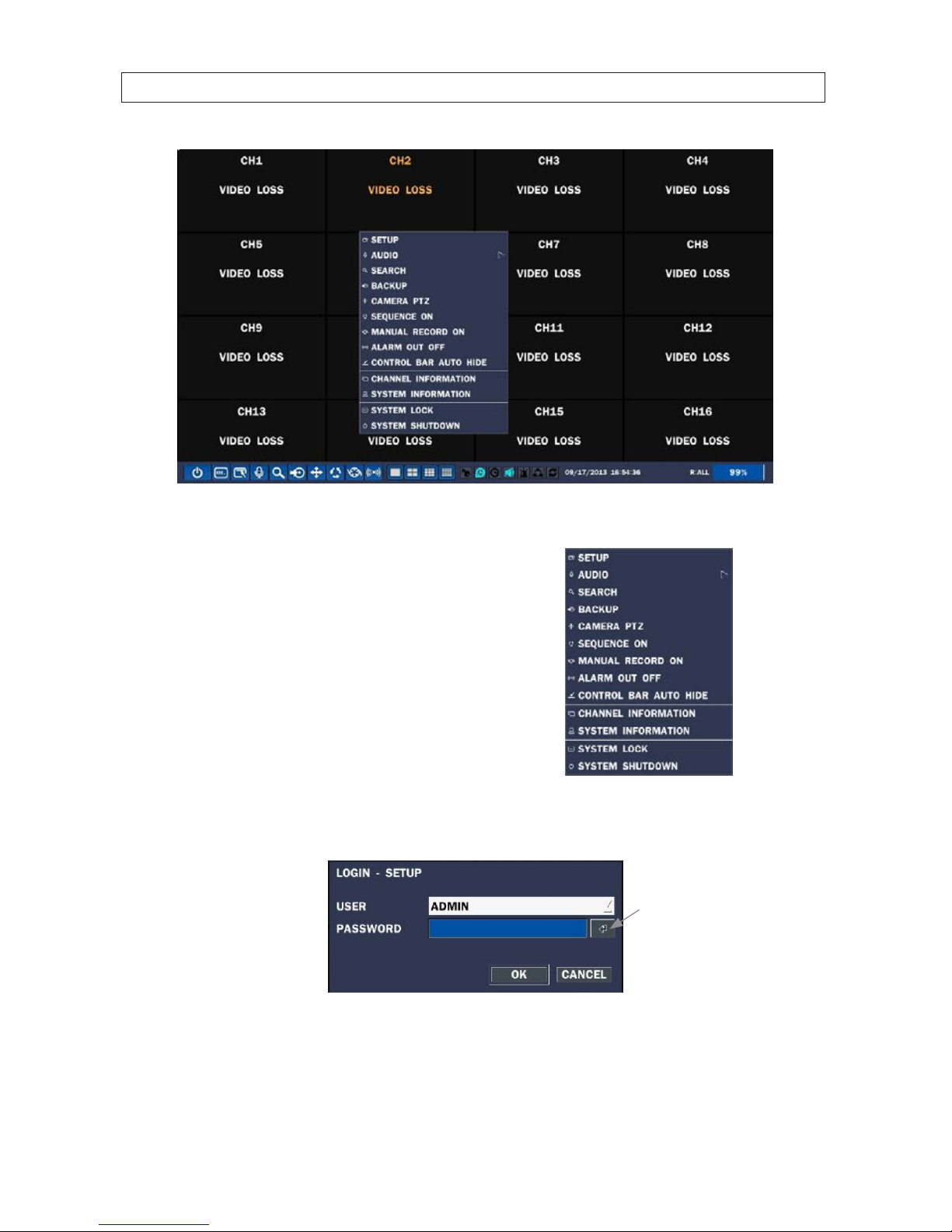
3.1.1 Entering the SETUP menu
1. To enter the SETUP menu, right click on the desktop or
press the SETUP button on the remote control, then click
the SETUP
entry in the pop-up menu. A LOGIN window
will open.
2. In the LOGIN window, open the virtual keyboard and enter the PASSWORD, or use the direction buttons on the front panel.
The default password is “1111”.
Virtual
Keyboard
Button
After entering the password in the virtual keyboard, click OK to close the keyboard display, then click OK again to login to the
SETUP menus.
20
SECTION 3: SYSTEM SETUP
NOTE
For improved security, change the password. You can select a new password through the SECURITY tab in the SETUP menu.
Open a menu by clicking the tab. To close the window, click Cancel. To save changes made to the menus before closing the
window, click OK.
For a summary of the elements in each SETUP submenu (tab), refer to Appendix C.
Navigating the menus
You can navigate through the menu system, change option values, and click buttons with the mouse. Entry elds usually
have drop-down menus you can open to select preset parameter values. Other parameters elds open submenus or
keyboards you can use to enter names and other values. You can also navigate through the menu items using the direction
button, p, q, t, or u and change option values with the SEL button. Always select (or click) OK to save new settings
and close the SETUP menus. Press the ESC button at any time to exit the SETUP menus.
NOTE
In the following descriptions of the SETUP menus, the instructions for navigating the system includes use of the front panel
buttons only. Using a mouse for menu navigation and setup of system options can be easier and faster.
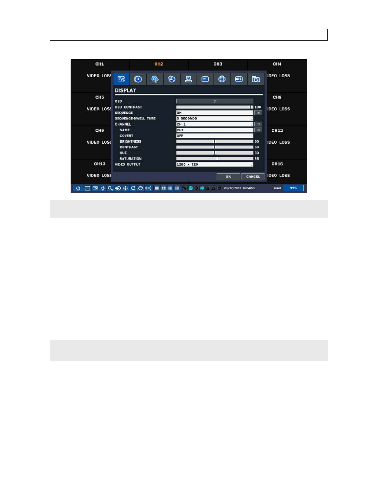
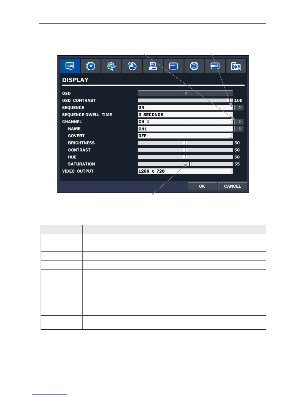
3.2 DISPLAY menu
Opening the SETUP menu, or clicking the DISPLAY tab, opens the DISPLAY menu.
21
960H H.264 DVR User Manual
SECTION 3: SYSTEM SETUP
Open Submenu
Drag to adjust
Open Drop-down List
Table 7. DISPLAY menu options
Item Description
OSD
Enable/disable the on-screen display.
OSD CONTRAST Set the visibility level of the OSD. (0 ~ 100)
SEQUENCE Enable/disable sequential display of video in full screen mode.
SEQ-DWELL TIME Set the dwell time of each quad-split or 9 -channel display in se quential display mode. (3 ~ 60 seconds)
CHANNEL In the channel submenu, you can tu ne the display settings for all cameras at once, or setup each camera individually. Click the
channel drop-down list to selec t the channel, then use the click t he submenu but tons to NAME the c hannel and set the COVERT
propert y (enable /disab le live display mode). Drag the marker on the image adjustment bars to per fect the image.
BRIGHTNESS: Change t he brightness value of the selected channel. (0 ~ 100)
CONTRAST: Change the contrast value of th e selected c hannel. (0 ~ 100)
HUE: Change the hue value of th e selected c hannel. (0 ~ 100)
SATUR ATION: Change t he saturation value of the selected channel. (0 ~ 100)
Click OK to save the se ttings and close th e window.
VIDEO OUTPUT
(HDMI / VGA)
Allows user to se t monitor output res olution fro m 720p 50Hz / 60H z, 1080i 50Hz / 60Hz, 1080p 50 Hz / 60Hz.
Click OK
.
22
SECTION 3: SYSTEM SETUP
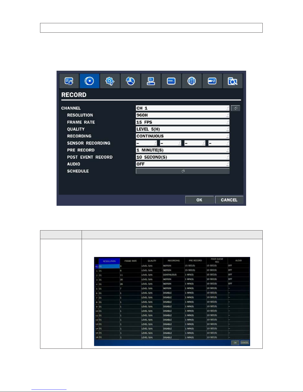
3.3 RECORD menu
Clicking the RECORD tab opens the RECORD menu.
Table 8. Menu Items in Recording Mode Setup
Menu Item Description
CHANNEL
In the Record Channel submenu, you can se t the recording modes for all cameras at once, or setup each camera individually.
Click th e submenu button to open the setup window. Clic k a eld to highlight it, clic k the down arrow in the eld, then s elect the
option you want f rom the drop-down menu. Click OK to save t he setting s and close the window.
23
960H H.264 DVR User Manual
SECTION 3: SYSTEM SETUP
Menu Item Description
RESOLUTION
Selec t either CIF, Half D1, D1, or 960H.
FRAME RATE Set the frame rate for the sp ecied channel (1 ~ 15 fps). The sum of the f rame rates from each channel c annot exceed t he maxi-
mum frame rate s for a specic recording resolution. See the Specications se ction for the maximum video frame o f your recorder.
QUALITY Select the reco rding quality for the specied channel (Level 1 (low) to Level 5 (high)).
RECORDING Assign the recording mode for each channel. Options are: Disable, Continuous, Motion,Sensor,Schedule.
PRE RECORD Enable/dis able pre-event recording. Options are OFF, 15 SEC, 30 SEC, 1 MIN, 3 MIN, 20 MIN.
POST EVENT RECORD Set the post event reco rding time duration for the sp ecied channel. (10 ~ 60 seconds)
SENSOR RECORDING Enable set ting up to 4 sens ors for the specied channel.
AUDIO Enable/disable audio recording for channel 1 .. 4 only.
SCHEDULE Click the submenu icon to open the recording schedule setup window. To congure this feature, see the sub -section Recording
Schedules below.
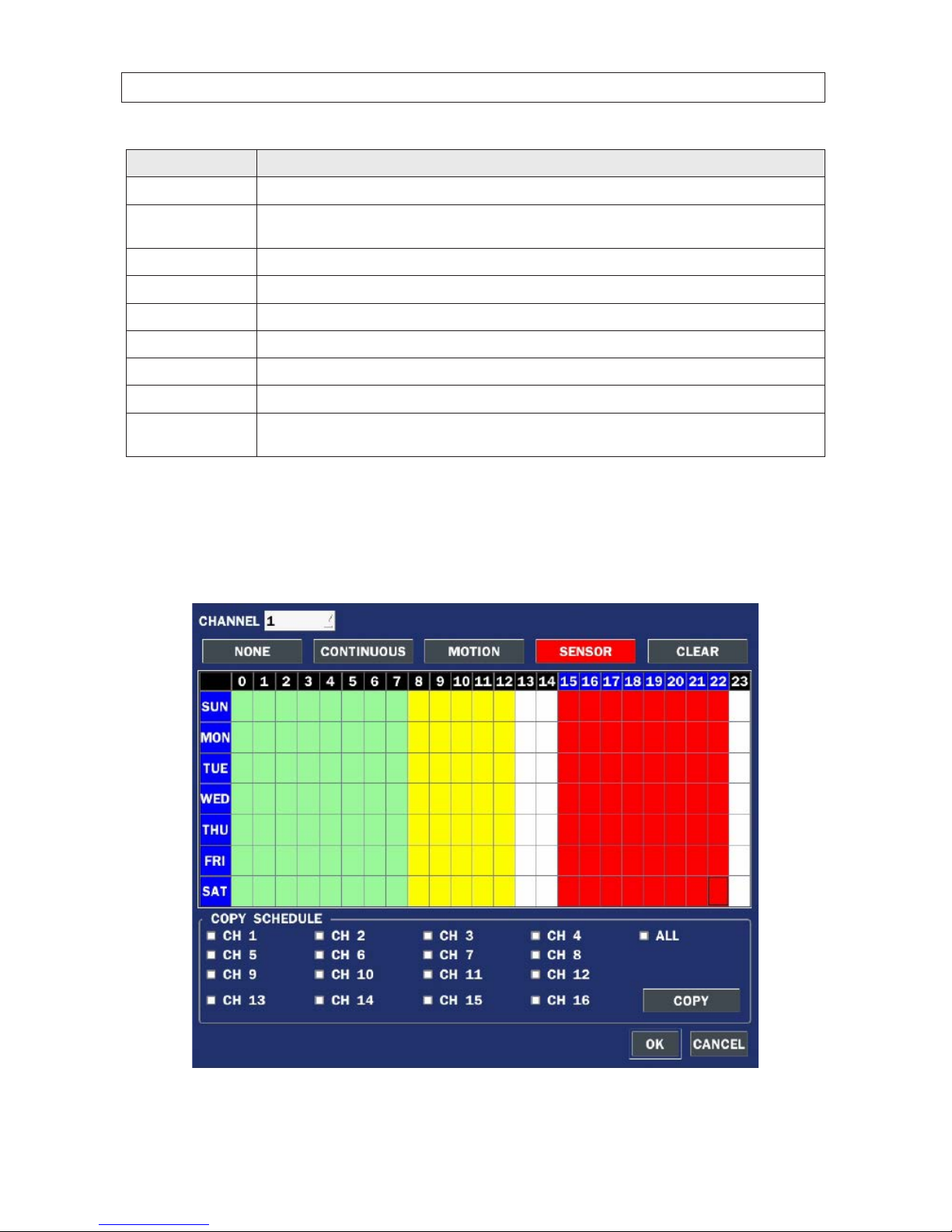
3.3.1 Recording Schedules
To setup a weekly recording schedule, click the SCHEDULE submenu bar in the RECORD menu. A recording mode (NONE,
CONTINUOUS, MOTION, or SENSOR) can be applied to any hour of the week for each camera.
24
SECTION 3: SYSTEM SETUP
Table 9. RECORD menu SCHEDULE setup
Menu Item Description
CHANNEL
Selec t the channel for the schedule you are s etting.
MODE Click th e recording mode (NONE, CONTINUOUS, MOTION, or SENSOR) to apply to the schedule, then dr ag the mouse cursor across
the days and hour s in the grid you where you w ant to use that mode. Time slots are color coded for the record mode applied to
them: CONTINUOUS - green, MOTION - yellow, and SENSOR - red, NONE - white.
COPY SCHEDULE
To copy the schedule you setup to other cameras, click the camera channel number(s), then click COPY.
You can also use the front panel buttons, p, q, t, u, and SEL buttons to perform these selections.
Click OK to save your settings.
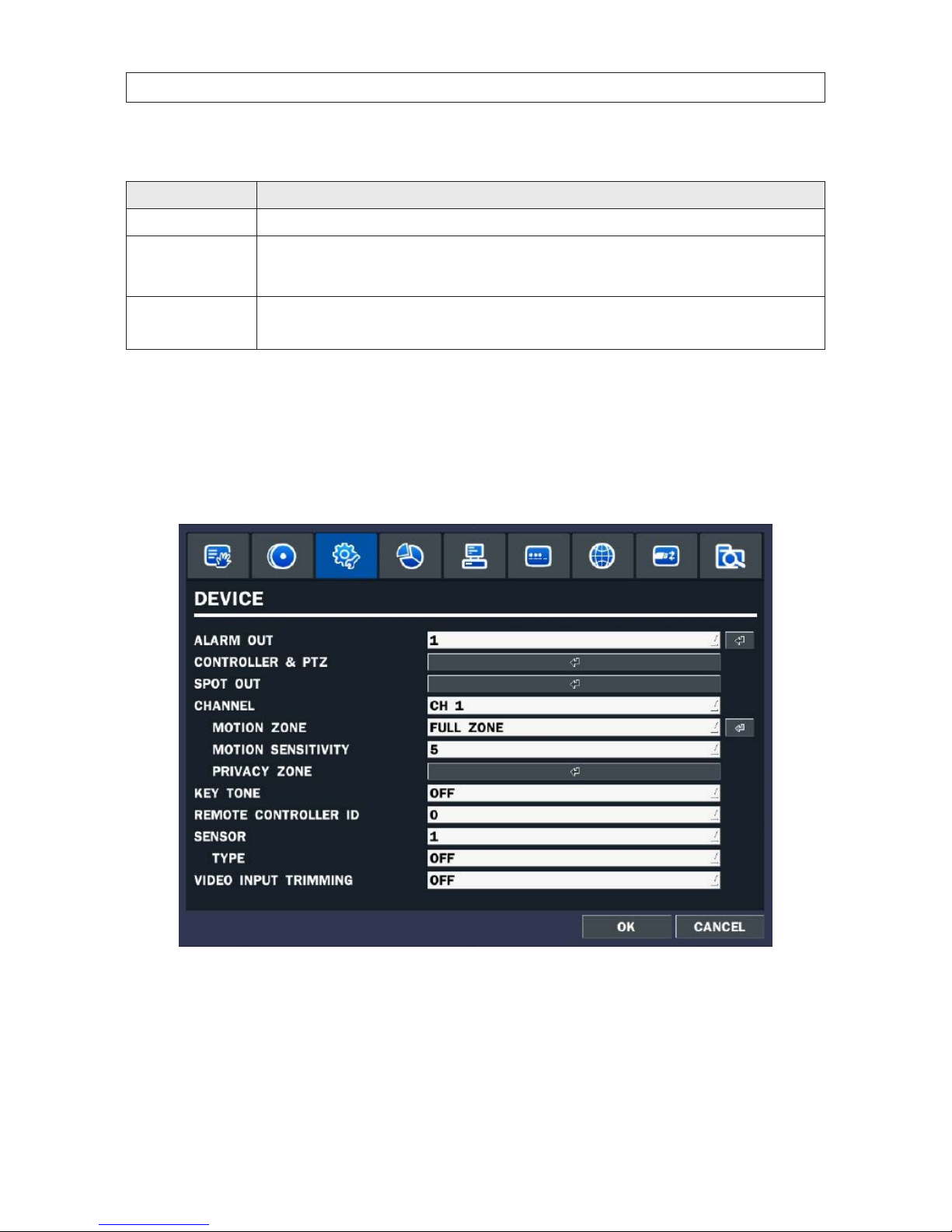
3.4 DEVICE menu
Clicking the DEVICE tab opens the DEVICE menu. To return to SETUP menu, press the ESC button.
 Loading...