

Page 1

Black Iris For Telecom & Technology
ETH-FE1
Ethernet over E1 Converter
Data Sheet & User Manual
Black Iris For Telecom & Technology
Sport City - Sarh Alshaheed St. - Al Gaber 2 Complex - Office 308 - P.O. 11947-570 Amman - Jordan
Phone : +962 6 5150369
Fax : +962 6 5150630
Mobile : +962 77 7411303
Email : [email protected]
Website : www.Black-iris.net
Black Iris For Telecom & Technology - 2008
1
Page 2
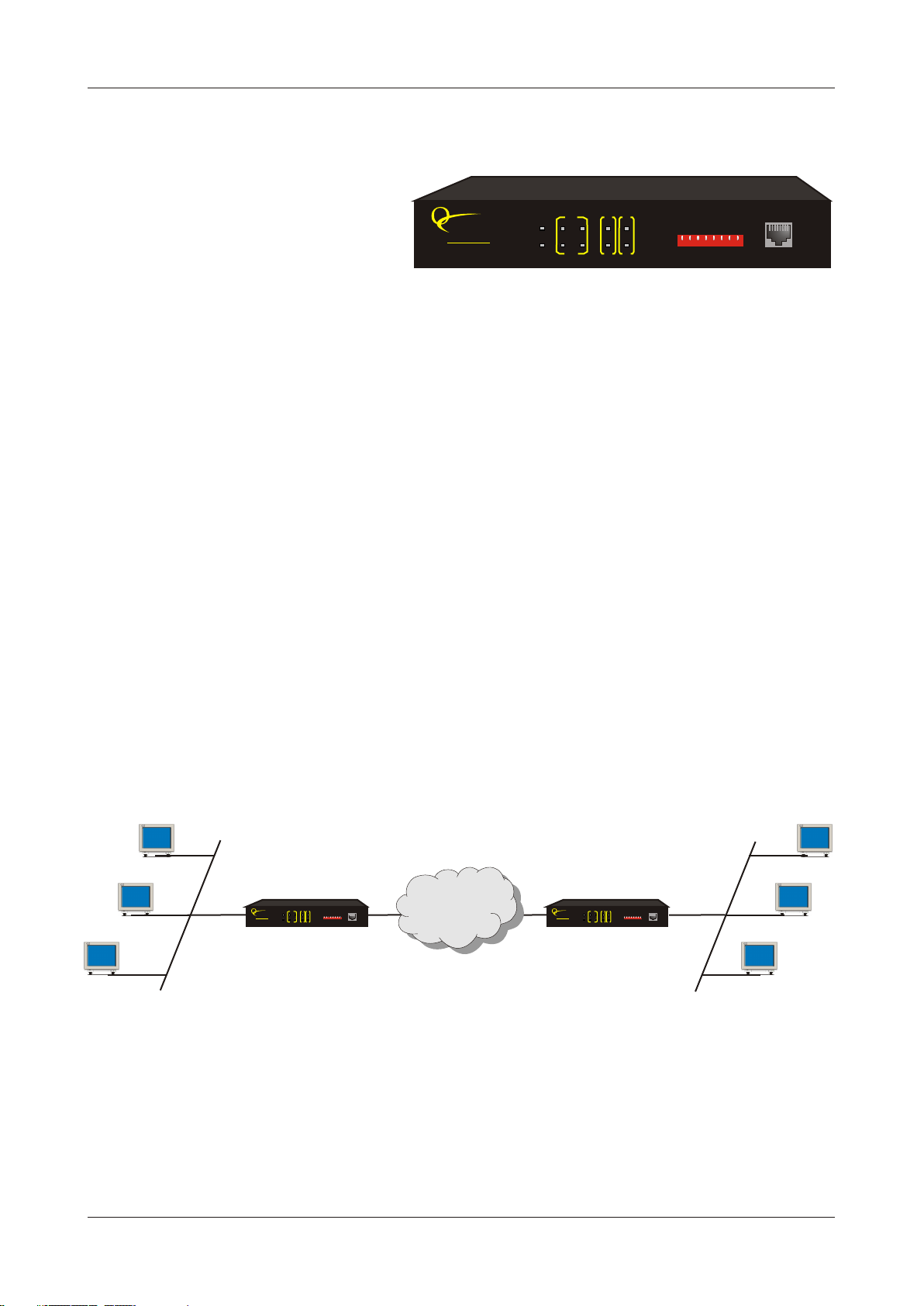
ETH-FE1
Product Overview
The Interface Converter
ETH-FE1
(Desktop Version) provides the user with
Ethernet over E1 conversion enabling the
user to transport Ethernet data over an E1
link.
The equipment can be installed and used
in pairs, with one terminal being installed
RION
TELECOM
NETWORKS
www.oriontelecom.com
VCL-ETH-FE1
E1
AIS LINK
PWR LOS
RA
CV FDX
LOF
ETH-FE1
LOOP
MASTER
TEST
GFP/HDLC
OFF
ERR
ON
6
2
738
4
5
1
TEST CONSOLE
ETH
at either end of the network. This
equipment can also be used with and to meet various application
ETH-16-MLETH-8-ML
requirements.
The Interface Converter is an Ethernet extension device utilizing TDM telecom
ETH-FE1
infrastructure (the telecom network of E1s, or of PDH, SDH and E1/E3/SDH microwave etc. carrying
E1s). It converts the Ethernet data into E1 frame format for transmission over the existing TDM (E1)
links and then re-converts the E1 back into Ethernet data the far-end terminal, to BRIDGE two Ethernet
LANs over the existing E1-based telecom network. The device can effectively utilize the redundant
bandwidth of telecom operators' existing TDM network to transport Ethernet data with low investment.
Application
The equipment may be used for the following purposes:
! Bridging Ethernet LANs over existing TDM (E1) telecom network.
! Extending Ethernet networks utilizing TDM (E1) landline based telecom infrastructure.
! Using telecom network of E1s/PDH/SDH microwave etc. carrying E1s to transport Ethernet data.
Typical Applications
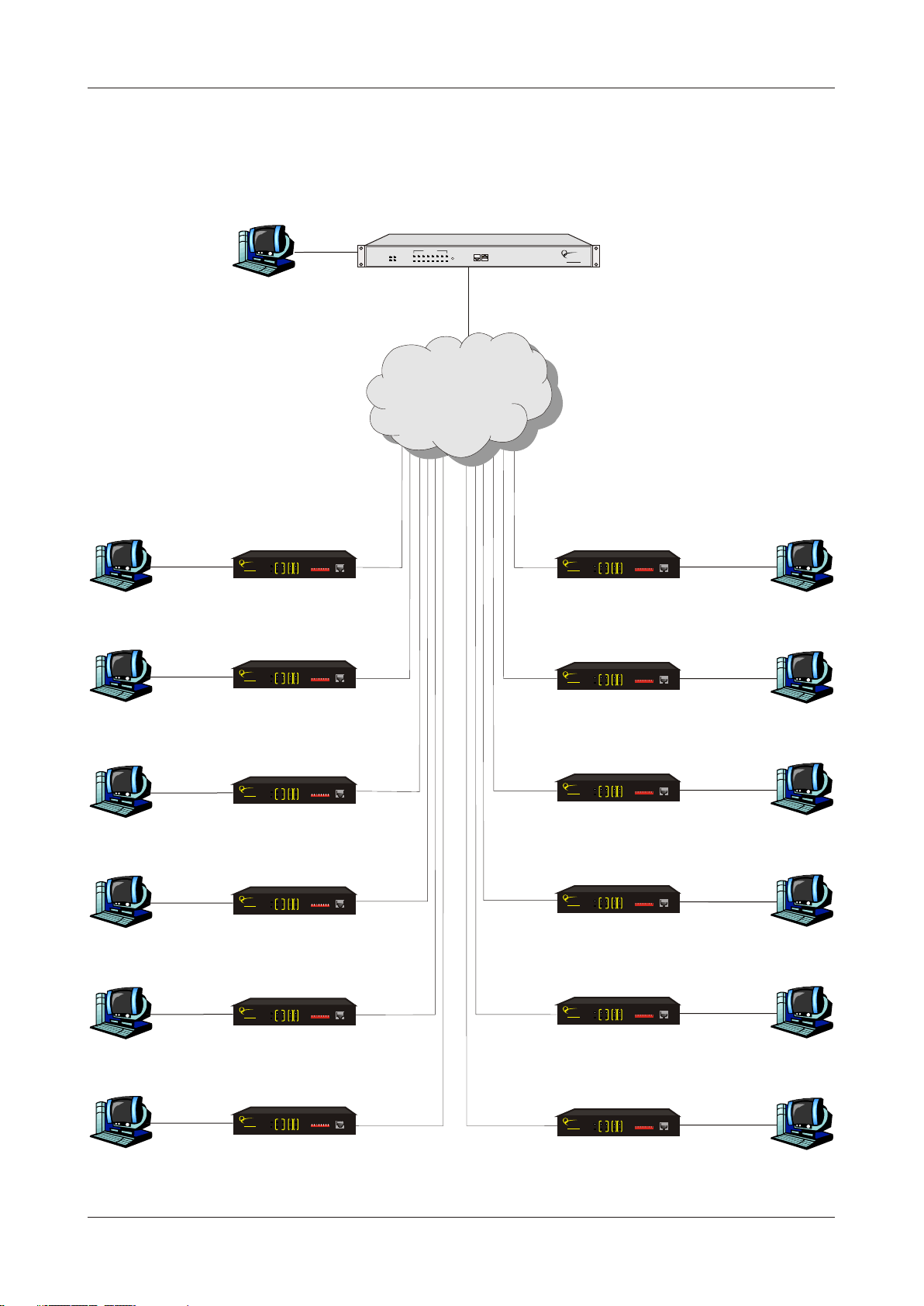
Point to Point Application
E1LAN LANE1
TELECOM
NETWORKS
www.oriontelecom.com
VCL-ETH-FE1
MASTER
TEST
GFP/HDLC
OFF
6
2
738
4
5
1
ON
RA
CV FDX
ERR
LOF
TEST CONSOLE
ETH
E1
RION
AIS LINK
LOOP
PWR LOS
VCL-ETH-FE1 VCL-ETH-FE1
Network carrying E1 Links
Network
E1 / E3 / SDH / PDH
TELECOM
NETWORKS
www.oriontelecom.com
VCL-ETH-FE1
TEST CONSOLE
ETH
E1
RION
AIS LINK
LOOP
PWR LOS
MASTER
TEST
GFP/HDLC
OFF
6
2
738
4
5
1
ON
RA
CV FDX
ERR
LOF
Black Iris For Telecom & Technology - 2008
4
Page 3
ETH-FE1
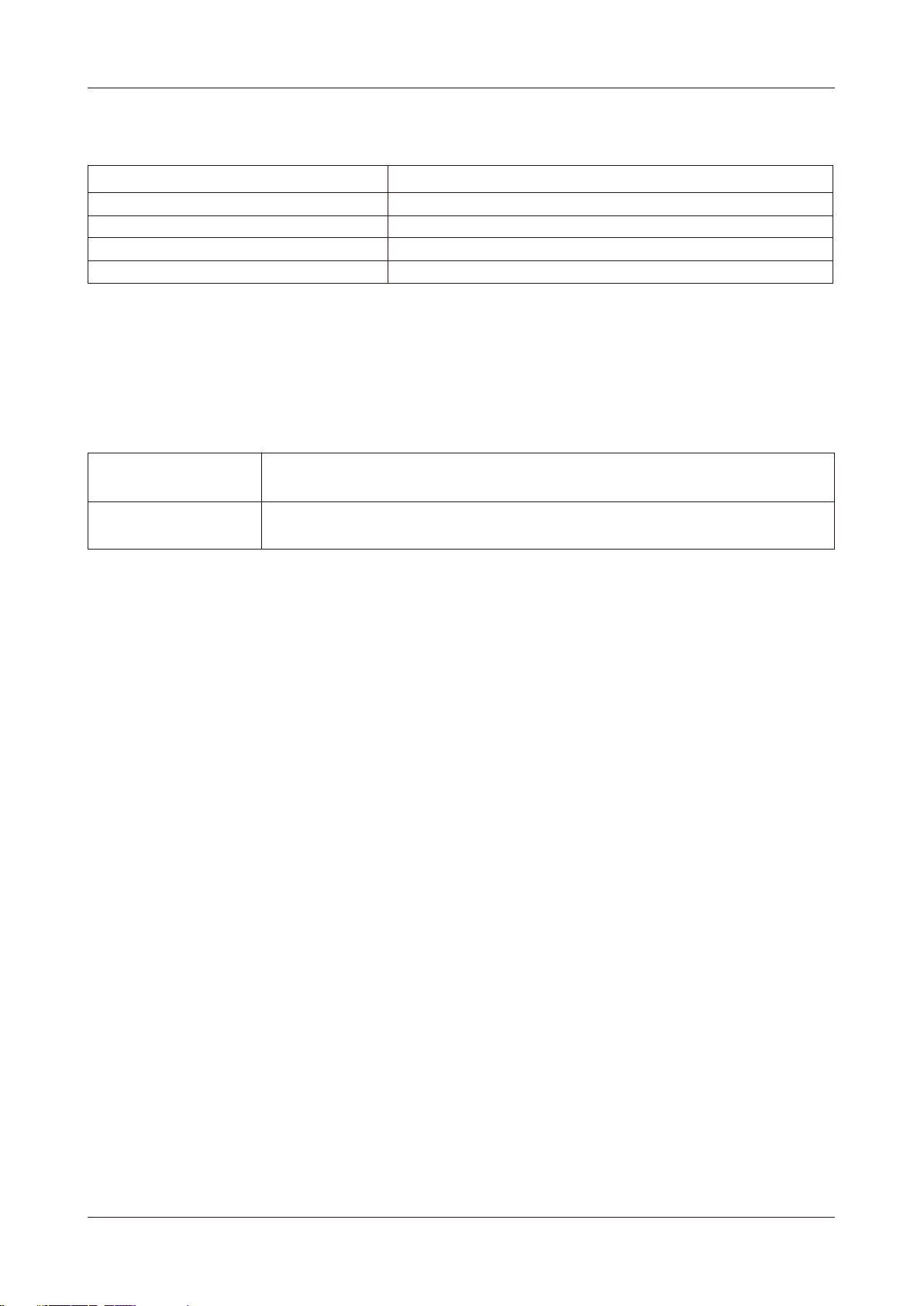
Point to Multi-Point
Remote Site 1
Ethernet
10/100
or ETH-16-MLApplication with ETH-8-ML
Central Site
Ethernet
10/100
VCL-ETH-16-ML
LAN
ETH-FE1 ETH-FE1
RION
TELECOM
NETWORKS
www.oriontelecom.com
VCL-ETH-FE1
E1
PWR LOS
AIS LINK
RA
LOF
CV FDX
TEST CONSOLE
ETH
LOOP
GFP/HDLC
TEST
MASTER
OFF
2
1
ON
ERR
1 E1 1 E1
6
738
4
5
ETH-16-ML
TRIBUTARY STATUS
1
ALM
PWR
CV_HISRUN
9210311412513614715816
CLR_CV
Upto 16E1
Channels
Network
CONSOLE EMU
TELECOM
NETWORKS
www.oriontelecom.com
RION
E1 / E3 / SDH / PDH
Network carrying E1 Links
E1
RION
PWR LOS
AIS LINK
TELECOM
NETWORKS
www.oriontelecom.com
RA
LOF
CV FDX
VCL-ETH-FE1
Remote Site 7
Ethernet
TEST CONSOLE
ETH
LOOP
GFP/HDLC
TEST
MASTER
OFF
2
4
5
1
ON
ERR
6
738
10/100
LAN
Remote Site 2
Ethernet
10/100
LAN
Remote Site 3
Ethernet
10/100
LAN
Remote Site 4
Ethernet
10/100
LAN
Remote Site 5
Ethernet
10/100
LAN
ETH-FE1
E1
RION
PWR LOS
AIS LINK
TELECOM
NETWORKS
www.oriontelecom.com
RA
LOF
CV FDX
VCL-ETH-FE1
ETH-FE1
E1
RION
PWR LOS
AIS LINK
TELECOM
NETWORKS
www.oriontelecom.com
RA
LOF
CV FDX
VCL-ETH-FE1
ETH-FE1
E1
RION
PWR LOS
AIS LINK
TELECOM
NETWORKS
www.oriontelecom.com
RA
CV FDX
LOF
VCL-ETH-FE1
ETH-FE1
E1
RION
AIS LINK
PWR LOS
TELECOM
NETWORKS
www.oriontelecom.com
RA
CV FDX
LOF
VCL-ETH-FE1
TEST CONSOLE
ETH
LOOP
GFP/HDLC
TEST
MASTER
OFF
2
4
5
1
ON
ERR
TEST CONSOLE
ETH
LOOP
TEST
GFP/HDLC
MASTER
OFF
2
4
5
1
ON
ERR
TEST CONSOLE
ETH
LOOP
MASTER
TEST
GFP/HDLC
OFF
2
4
5
1
ON
ERR
TEST CONSOLE
ETH
LOOP
GFP/HDLC
MASTER
TEST
OFF
2
4
5
1
ON
ERR
LAN
Remote Site 8
1 E1
6
738
1 E1
RION
TELECOM
NETWORKS
www.oriontelecom.com
VCL-ETH-FE1
E1
PWR LOS
AIS LINK
RA
LOF
CV FDX
TEST CONSOLE
ETH
LOOP
GFP/HDLC
TEST
MASTER
OFF
2
4
5
1
ON
ERR
6
738
ETH-FE1
Ethernet
10/100
LAN
Remote Site 9
1 E1
6
738
1 E1
RION
TELECOM
NETWORKS
www.oriontelecom.com
VCL-ETH-FE1
E1
PWR LOS
AIS LINK
RA
LOF
CV FDX
TEST CONSOLE
ETH
LOOP
GFP/HDLC
TEST
MASTER
OFF
2
4
5
1
ON
ERR
6
738
ETH-FE1
Ethernet
10/100
LAN
Remote Site 10
1 E1
6
738
1 E1
RION
TELECOM
NETWORKS
www.oriontelecom.com
VCL-ETH-FE1
E1
PWR LOS
AIS LINK
RA
LOF
CV FDX
TEST CONSOLE
ETH
LOOP
GFP/HDLC
TEST
MASTER
OFF
2
4
5
1
ON
ERR
6
738
ETH-FE1
Ethernet
10/100
LAN
Remote Site 11
1 E1
6
738
1 E1
RION
TELECOM
NETWORKS
www.oriontelecom.com
VCL-ETH-FE1
E1
AIS LINK
PWR LOS
RA
CV FDX
LOF
TEST CONSOLE
ETH
LOOP
MASTER
GFP/HDLC
TEST
OFF
2
4
5
1
ON
ERR
6
738
ETH-FE1
Ethernet
10/100
LAN
Remote Site 6
Ethernet
10/100
LAN
Black Iris For Telecom & Technology - 2008
ETH-FE1
RION
TELECOM
NETWORKS
www.oriontelecom.com
VCL-ETH-FE1
E1
AIS LINK
PWR LOS
RA
CV FDX
LOF
TEST CONSOLE
ETH
LOOP
MASTER
TEST
OFF
2
1
ON
ERR
1 E1
GFP/HDLC
6
738
4
5
Up to 12 Remote Sites / Directions and 16 E1 Links
1 E1
ETH-FE1
E1
RION
AIS LINK
PWR LOS
TELECOM
NETWORKS
www.oriontelecom.com
RA
CV FDX
LOF
VCL-ETH-FE1
Remote Site 12
Ethernet
TEST CONSOLE
ETH
LOOP
MASTER
GFP/HDLC
TEST
OFF
2
4
5
1
ON
ERR
6
738
10/100
LAN
5
Page 4

ETH-FE1
Technical features
! 1U high compact size
! The maximum transmission rate of Ethernet data over E1 links is 2.048Mbit/s
! E1 supports three working modes unframed, framed (CCS/PCM 31) and multiple framed
(CAS/PCM30)
! Allows transparent transmission of super-long frames upto 2024 bytes
! Automatic discards under size (less than 64 bytes) and oversize (more than 2024 bytes) framed
! Ethernet interface complies to IEEE 802.3
! Automatic Ethernet negotiation function. Supports 10M/100M and working modes of both full-
duplex and half-duplex
! Automatic straight and cross-over cable support (Auto-MDI/X)
! Available with MAC address list filtration, learning, and updating functions
! PAUSE flow control ability in full duplex mode
! Equipment supports two working modes of internal clock and network Loop-timed clock
! With multiple loopback functions and built-in bit error testing function, it facilitates the trouble
shooting
! Compatible to deluxe models (VCL-ETH-4/8/16 and VCL-ETH-8/16-ML) and can be installed
with them to reduce the installation cost
! Easy to operate
! Power supply options:
= 110V AC - 240V AC (50/60 Hz) power options available
= -48V DC power option available
! Power consumption less than 4Watts.
Alarms and Indicator Monitoring
! Power Indicator
! Remote Alarm Indicator
! Loss of Frame Indicator
! E1 LOS Alarm Indicator
! AIS Alarm Indicator
! Code Violation Alarm Indicator
! Ethernet Link Indicator
! Ethernet Mode (FDX) Indicator
! Loopback Indicator
! Error in Test Indicator
E1 Interface Specifications
Line Rate E1 (2.048 Mbps ± 50 bps)
Framing Un-Framed /PCM 30 /PCM 31
Electrical As per ITU-T G.703 and ITU-T G.704
Jitter As per ITU-T G.742 and ITU-T G.823
Impedance 120 Ohm (RJ-45)
Impedance 75 Ohm (BNC) Optional
Black Iris For Telecom & Technology - 2008
6
Page 5
ETH-FE1
Ethernet Port Specifications
Interface Types 10/100BaseT
Standards Compliance IEEE 802.3
Connectors RJ-45 (10/100 BaseT Electrical)
MDI-X Supported (auto adapts cross-straight cable)
Mode Autonegotiation (Half/Full - 10/100M)
Clock
Internal (Master) and network (Slave) clock.
Encapsulation
HDLC HDLC mode is required in installation between two VCL-ETH-FE1
(point to point protocol) if fractional E1 is used to carry payload
GFP GFP Mode is must, to use the VCL-ETH-FE1 in point to multi point
Protocol with Delux models (VCL-ETH-4/8/16 and VCL-ETH-8/16-ML)
Black Iris For Telecom & Technology - 2008
7
Page 6

ETH-FE1
Installation and Commissioning
1 Qualifying the network
! Please ensure that the error code rate each of the E1 circuits connecting to the equipment is
lower than 10
-7.
! The transmission time delay difference between the various E1 circuits shall not exceed 8ms.
! The Ethernet wire type shall be, crossover when connecting with PC, and straight through when
connecting to an Ethernet switch/HUB. The length of the ethernet cable shall not exceed 100m.
2 Grounding
! When the device is used with the AC~220V power supply, the 3-core socket must be grounded
for protection.
! The other equipment connected with the converter shall also be grounded to earth for protection.
3 Installation
Step 1: Power up the equipment. Please ensure that equipment is powered-up prior to connecting
the Ethernet and the E1 links.
Step 2: Connect E1 line on the premise that transmission device, interface converter and E th er ne t
converter have safely grounded.
BER test may be conducted on each E1 link using a BERT tester to ensure that the E1 errors
are within the permitted limits / threshold.
Step 3: Please configure the ethernet mode of the Ethernet over E1 equipment at both sides as well
as the ethernet interfaces of the devices that are connected to the Ethernet over E1
equipment. Connect the ethernet links.
The equipment is used to bridge two LANs. Please ensure that the LANs on both sides of the
link are operating in the same IP domain.
Step 4: Ping over the ethernet connection from one side to the other (near-end to the far-end) to
verify that the Ethernet connection has been established between the two LANs.
After succeeding in "ping", the user may also check the integrity of each E1 link by connecting E1 link
and then transporting ethernet data over that E1 link. In the event that the equipment resets repeatedly
or lots of frame errors are noticed, recheck the connection between E1 cable and interface converter,
or E1 cable and transmission device.
Black Iris For Telecom & Technology - 2008
8
Page 7
ETH-FE1
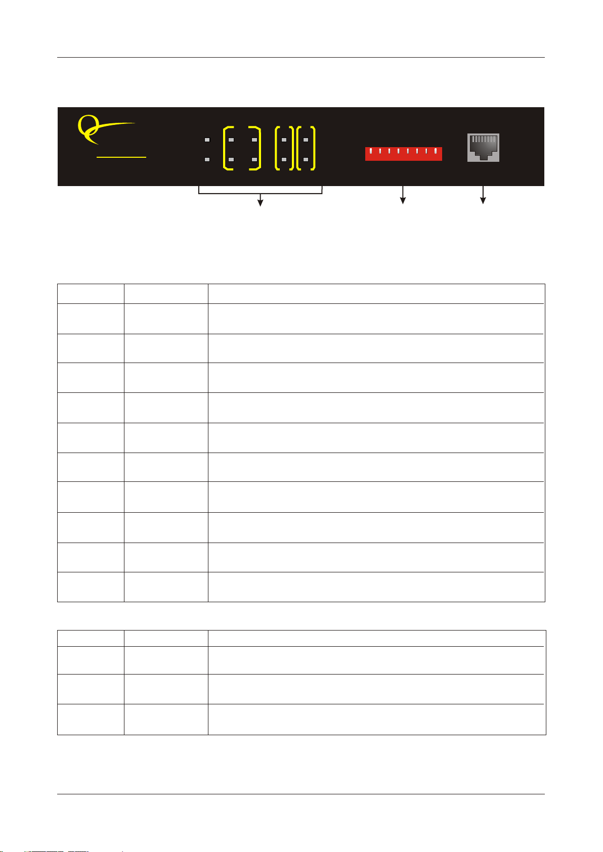
Description of the Front Panel
RION
TELECOM
NETWORKS
www.oriontelecom.com
PWR LOS
RA
ETH-FE1
LOF
E1
AIS LINK
CV FDX
TEST CONSOLE
ETH
LOOP
ERR
OFF
ON
TEST
MASTER
GFP/HDLC
2
1
6
738
4
5
Configuration
Switches
Switches
Console PortConfiguration
Definition of Indicators on front panel
LED Status Description
PWR ON Green, system is powered
OFF System is not powered
RA ON Red, remote alarm indication
OFF OK
LOS ON Red, Loss of E1 alarm indication
OFF OK
LOF ON Red, Loss of E1 frame indication
OFF OK
AIS ON Red, AIS alarm idication
OFF OK
CV ON Red, E1 code violation alarm indication
OFF OK
LINK ON Green, LAN port connection Normal
OFF No LAN connection on Ethernet port
FDX ON Green, Ethernet port is running in full-duplex mode
OFF Ethernet port is running in half-duplex mode
LOOP ON Yellow, system is in test mode
OFF Normal operation mode
ERR ON Red, Error in BER test E1 Signal
OFF BER test OFF or has no errors
Switch Status Description
MASTER ON local timing
OFF tracing E1 line
TEST ON line error testing, Led “ERR” show the testing result
OFF turn off line error test function
GFP/HDLC ON HDLC framing
OFF GFP framing
Black Iris For Telecom & Technology - 2008
9
Page 8
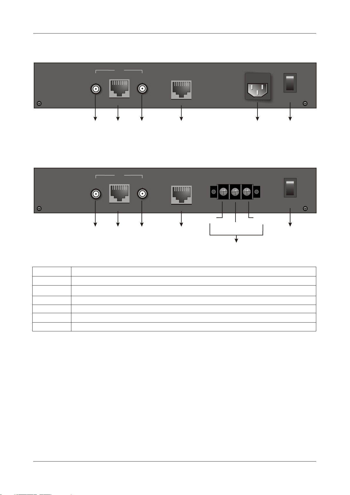
ETH-FE1
Back View with 220V AC power Input
75W
IN
120W
OUT
220
V
OFF
O
I
E1
Input
E1 75W
E1 Port
120W
Output
E1 75W
Back View with 48V DC power Input
75W
IN
Input
E1 75W
120W
E1
E1 Port
120W
OUT
Output
E1 75W
ETH
Ethernet
Port
ETH
Ethernet
Port
Ground
PGND GND
Negative
48V DC Inlet
AC 220V
Inlet
-48V
Positive
ON
ON/OFF
Switch
OFF
O
I
ON
ON/OFF
Switch
Tag Description
IN 75W Represents the unbalanced E1 75W input (BNC)
OUT 75W Represents the unbalanced E1 75W Output (BNC)
120W Represents the balanced E1 120W input/output (RJ-45)
ETH Fast Ethernet interface (RJ-45)
220V Represents AC 220V inlet
48V Represents DC 48V inlet
Black Iris For Telecom & Technology - 2008
10
Page 9
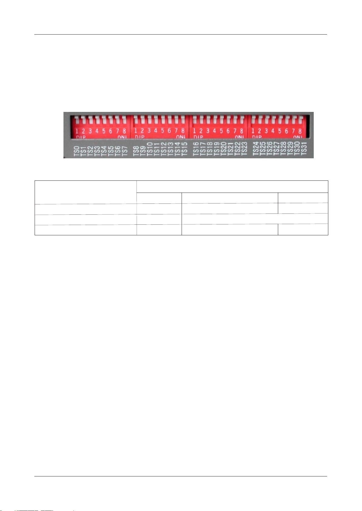
ETH-FE1
E1 Bandwidth Selection
For E1 bandwidth selection, Effective only if the encapsulation mode is set to 'HDLC' (i.e. GFP /
HDLC switch is set to 'ON'), the DIP Switch settings on the right side panel are as follows:
OFF
ON
Working Mode Switch Setting
TS0 TS1-15, 17-31 TS16
Unframed / PCM 31 ON ON ON
Framed (CCS) / PSM 31 OFF Occupied timeslot ON
Multi Framed (CAS) / PCM 30 OFF Occupied timeslot ON OFF
Effective only if the encapsulation mode is set to ‘HDLC’. GFP/HDLC switch is set to ‘ON’
Example 1: If you wish to use only first 5 time slots then you need to set the TS0 time slots to OFF
and switch TS1 to TS5 to ON and time slot TS16 will be set to ON.
Example 2: If you wish to carry first 8 time slots on 512Kbps, then you need to set the TS0 time slot
OFF and switch TS1 to TS8 to ON (i.e. since each time slot consumes 64Kbps, so 8
time slots will consume 8 x 64Kbps = 512Kbps) and time slot S16 will be set to ON.
Example 3: If you wish to carry 20 time slots on 1.28Mbps (64Kbps x 20) then you need to
set time slot TS0 OFF and TS1 to TS21 time slots to ON. Please remember that the
time slot TS16 will be used as signaling time slot.
Black Iris For Telecom & Technology - 2008
11
Page 10
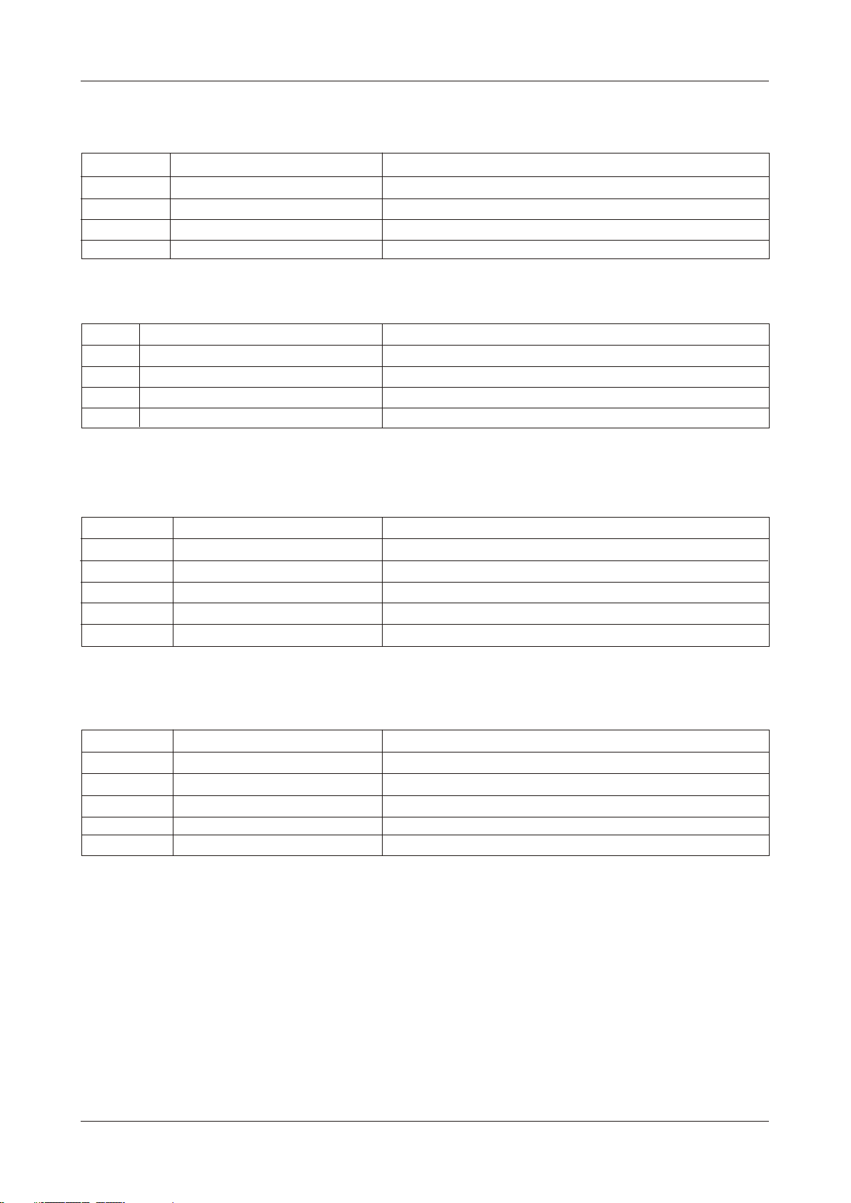
ETH-FE1
Console (RJ-45) Pinout Details
PIN No. Definition of function Signal Direction
6 GND Signal Ground
7 RX (received data) RS232 Signal Input
8 TX (transmitted data) RS232 Signal Output
Others NC
HyperTerminal settings should be as follows:
1 Bits per second 19200
2 Data bits 8
3 Parity None
4 Stop bits 1
5 Flow control None
E1 120W (RJ-45) Pinout Details
PIN No. Definition of function Signal Direction
1 TX+ (transmitted data +) E1 Data Output
2 TX- (transmitted data -) E1 Data Output
4 RX+ (received data +) E1 Data Input
5 RX- (received data -) E1 Data Input
Others NC
Ethernet (RJ-45) Pinouts
PIN No. Definition of function Signal Direction
1 TX+ (transmitted data +) Data Output
2 TX- (transmitted data -) Data Output
3 RX+ (received data +) Data Input
6 RX- (received data -) Data Input
Others NC
Black Iris For Telecom & Technology - 2008
12
Page 11

ETH-FE1
CLI Commands List
After entering into the application program for CLI command, please key "?" In the
command line to get the list of the commands.
VCL>?
Command Description
============ ====================================================
?/Help To get a list of the commands for the system.
showversion View software and hardware version.
showe1alarm View E1 alarm.
seteth Configure the Ethernet port Speed,Mode,Auto Negotiation.
showeth View Ethernet port status.
showframe View framing status.
showclock View E1 clock mode.
showencapmode View encapulation mode.
setgfp Configure PFI, EXI,PSCRD and HSCRD of GFP.
showgfp View PFI,EXI,PSCRD and HSCRD of GFP.
More help for a particular CLI Command
For detailed command format, please key "? cmdname" or "help cmdname".
VCL>? [cmdname] {enter}
OR
VCL>help [cmdname] {enter}
Example:
VCL>? showe1alarm
<FORMAT>: showe1alarm
<EXPLANATION>: View E1 alarm.
<PARAMETER>: none
Detailed CLI Command
To view system software and hardware version
<FORMAT>: showversion
<EXPLANATION>:View software and hardware version.
<PARAMETER>:none
Example:
VCL>showversion
IC version:V1.000
Hardware version:V1.12
Software version:V1.00A1
Black Iris For Telecom & Technology - 2008
13
Page 12

ETH-FE1
To view E1 alarm
<FORMAT>:showe1alarm
<EXPLANATION>:View E1 alarm.
<PARAMETER>:none
Example:
VCL>showe1alarm
ALARM LOS LOF AIS CRC
Status 0 0 0 0
Description 1:Alarm, 0:No alarm
To configure Ethernet port
<FORMAT>:seteth <AN> <speed> <duplex> <flow>
<EXPLANATION>:Configure the Ethernet port Speed, Mode, Auto Negotiation.
<PARAMETER>:
AN:<0/1>,Autotiation(0:AN not done; 1:AN done)
speed:<0/1>,(0:10Mbit/s; 1:100Mbit/s)
duplex:<0/1>,(0:half-duplex; 1:full-duplex)
flow:<0/1>,flow-control capability(0:disable; 1:enable)
Example:
VCL>seteth 1 1 1 1
AN Speed Duplex Flow
Auto 100M Full Enable
To view Ethernet port status
<FORMAT>:showeth
<EXPLANATION>:View Ethernet port status.
<PARAMETER>:none
Example:
VCL>showeth
AN Speed Duplex Flow Status
Not Auto 10M Half Disable Connected
To view framing status
<FORMAT>:showframe
<EXPLANATION>:View framing status.
<PARAMETER>:none
Black Iris For Telecom & Technology - 2008
14
Page 13

ETH-FE1
Example:
VCL>showframe
Frame status:Frame.
PCM30/31 status:PCM31
To view synchronization clock
<FORAMT>:showclock
<EXPLANATION>:View E1 clock mode.
<PARAMETER>:none
Example:
VCL>showclock
E1 Clock:Master
To view encapsulation mode
<FORAMT>:showencapmode
<EXPLANATION>:View encapsulation mode.
<PARAMETER>:none
Example:
VCL>showencapmode
The encapulation mode is:HDLC
To configure GFP
<FORMAT >: setgfp <PFI> <EXI> <PSCRD> <HSCRD>
<EXPLANATION>: Configure PFI, EXI, PSCRD and HSCRD of GFP.
<PARAMETER>: PFI: 0-1
EXI: 0-15
PSCRD: 1:enable ; 0:disable
HSCRD: 1:enable ; 0:disable
Example:
VCL>setgfp 0 0 1 1
PFI:0
EXI:0
PSCRD:Enable
HSCRD:Enable
Black Iris For Telecom & Technology - 2008
15
Page 14

ETH-FE1
To view GFP configurations
<FORMAT >: showgfp
<EXPLANATION>: View the PFI, EXI, PSCRD and HSCRD of GFP.
<PARAMETER>: none
Example:
VCL>showgfp
PFI:0 EXI:0
PSCRD:Enable
HSCRD:Enable
GFP SYNC:Alarm
General
Power Supply
AC Mains Input 220V AC Optional
DC Mains Input -48V
Power Consumption <4 Watts
Service Conditions
Ambient temperature 0 C ~ 50 C
Relative humidity 90% (at 35 C)
0 0
0
Dimensions
238mm x 125mm x 44mm
Weight
980gm
Black Iris For Telecom & Technology - 2008
16
 Loading...