


MiniRaQ
MiniRaQ Installation Overview
(TM*)
Congratulations on your purchase of the MiniRaQ vertical rack system. The MiniRaQ
(TM) (TM)
is available in 4U, 6U and 8U sizes based on size and usage restrictions for a variety of
applications. The is designed from heavy gauge steel and finished to last a lifetime.
MiniRaQ
(TM)
It is designed to hold up to 400 pounds when properly installed for your most demanding
needs such as extended runtime battery back up systems, low profile power distribution
transformers, POE equipment and many other rack mountable products.
For installing the MiniRaQ System into any other surface not specifically
(TM)
mentioned in this manual, please consult local building code requirements
Warning
The MiniRaQ System can be mounted on a variety of vertical substrates including
to insure safe and secure installation.
(TM)
wooden framing studs 16” on center, solid or block concrete walls, and approved
plywood electrical panel or directly onto existing 2 Post racking. Please see detailed
instructions on the following pages.
Mounting hardware is provided for installing into solid wall studs and #12-24
screws for mounting on 2 Post rack. The can even be mounted in a 2 Post rack
MiniRaQ
(TM)
Back-to-Back configuration if clearances allow, which may increase U space utilization
in some instances.
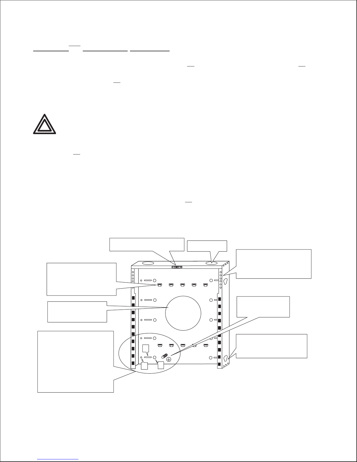
Lances are incorporated into the
(TM)
MiniRaQ to allow data and
power cable management for
input and output wiring using
either top or bottom egress,
as well as to facilitate service loops.
Large rear panel access allows
pass though cable routing in
2 Post Back-to-Back
mounting applications
Back-plate of is designed with
3 mounting options:
“A” hole pattern (10)
in standard 2 post open frame rack.
“B” Slots are centered at 16 inches
for #10 by 2” screws (10) into studs
or other solid wood surface.
“C” hole pattern (10)
toggle bolts for mounting on block wall
or NEC electrical panel grade plywood.
apparatus
allows mounting
accommodates
All Trademarks are the property of their respective owners. *Patents pending.
Built in level allows easy installation
for single service personnel
Top access for data
or power cabling
B
C
A
FIGURE 1
BlackHawk Labs, LLC Copyright 2007
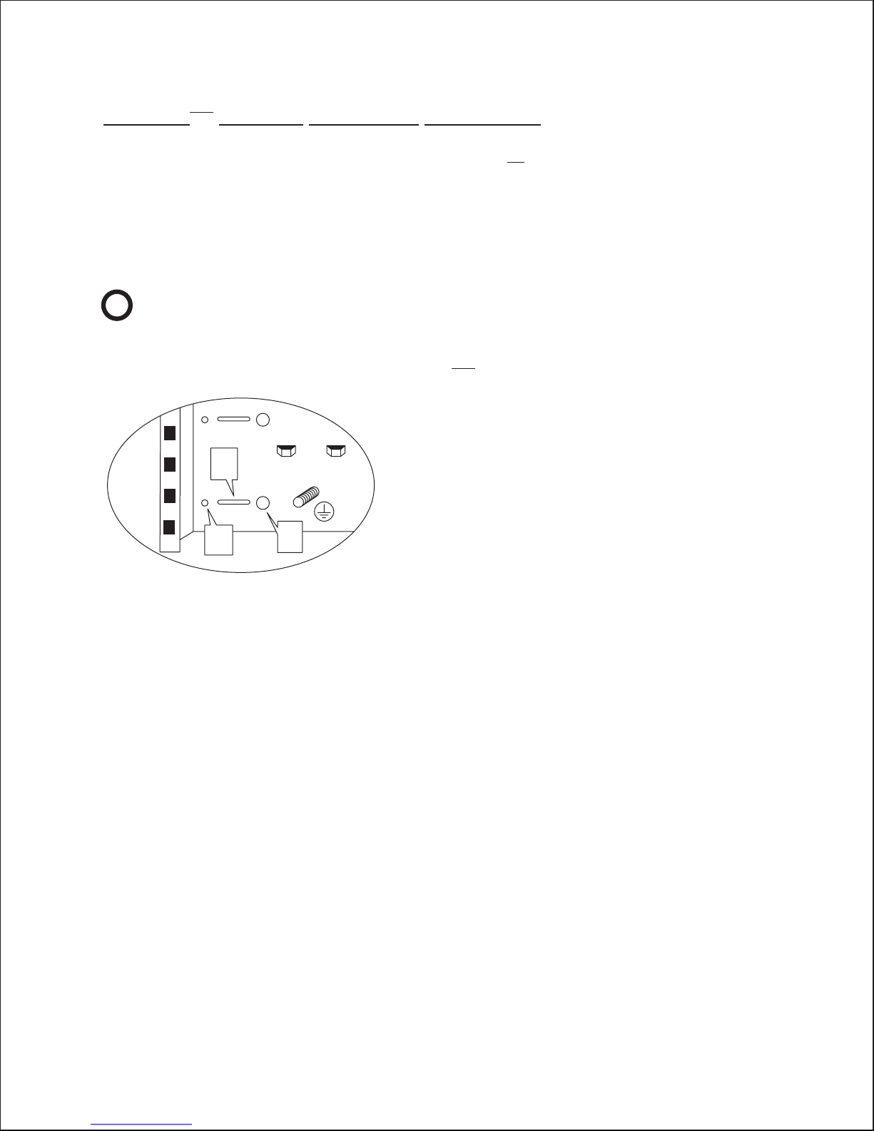
The apparatus allows attachment
for 1U or 2U patch panel directly
inside the back-panel without
sacrificing any space in the mounting
surface of the side panels.
Earth Grounding Stud
integrated further
assisting quick and
convenient system install
Ancillary equipment, both rack
and non-rack mountable, can be
attached to the side of the
back-panel by hanging or screwing
onto the back-panel.
www.miniraq.com
PAGE 1
MiniRaQ Installation Instructions
(TM)
Detailed
First confirm that the main back panel of the MiniRaQ will be mounted onto a
recommended surface and be sure proper hardware is available to proceed.
Hardware is supplied for both 2 Post rack (kit contains 10 #12-24 relay rack screws)
and wooden framing studs 16” on center (kit contains 10 #10 x 2” Stainless Steel screws).
If installing into concrete or approved plywood electrical panel be sure to have
appropriate 1/4” hexhead concrete screws**, lag bolt inserts* or toggle bolts* before
continuing with installation.
10 fasteners are recommended for full rated load
*
!
**10 fasteners are recommended for full rated load
Note
Mounting main back panel for MiniRaQ
B
(TM)
Close up detail of
(TM)
Mounting hole patterns
for different hardware options
A
C
Available to install the
MiniRaQ System
(TM)
FIGURE 2
2 Post Rack mounting option
(Hole Pattern A)......................................................................Page 3
Mounting into 16 inches on center
solid wood wall studs (Hole Pattern B)..............................Page 4
Mounting to Cinder Block or Approved
Hollow Wall (Hole Pattern C)...............................................Page 5
Mounting to Concrete Wall with
Compression Lags (Hole Pattern C)....................................Page 6
Mounting to Concrete Wall with TAPCON® bolts
(Hole Pattern C)......................................................................Page 6
Bracket Installation Details
Specifications and Warranty Information........................Page 8
..........................................Page 7
www.miniraq.com
PAGE 2
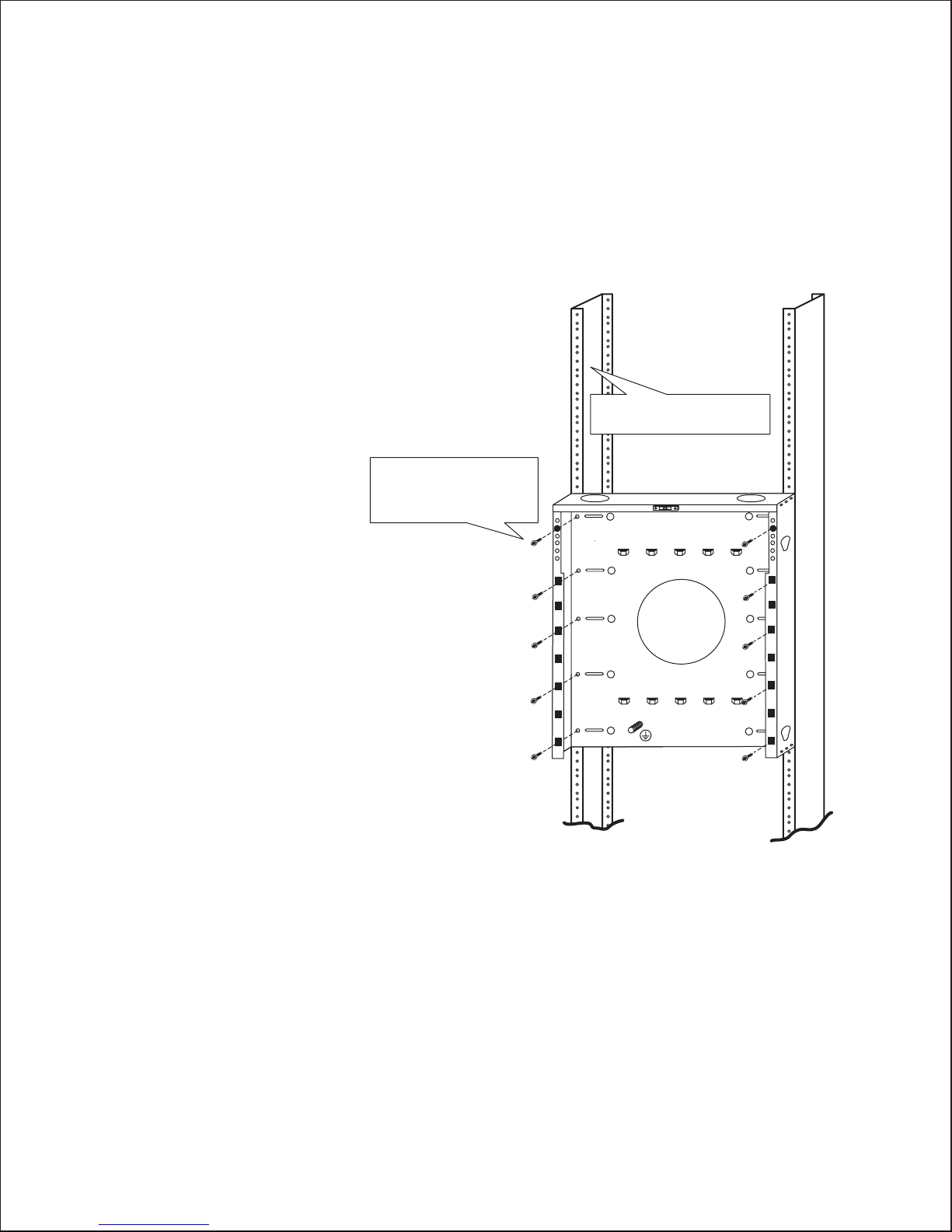
2 Post Rack mounting option (Hole Pattern A)
Using supplied #12-24 screws align and
insert 1 screw. Do not fully tight screw but
engaged enough to hold up back panel.
Using integrated level, adjust panel and
add second screw to opposite post.
Add remaining 8 screws
and then tighten all.
Next go to bracket
installation details (pg 7).
Begin installing #12-24 Screws
at the top using the integrated
Level to locate proper mounting
pattern. 10 screws recommended
for full payload rating of system.
Close up detail of
2-Post Mounting option
Secure both top and bottom of
2 Post Relay Rack before loading
(TM)
MiniRaQ
FIGURE 3
www.miniraq.com
PAGE 3
 Loading...