

BLACKHAWK! USB560 Quick Start Manual

1 4
This equipment is designed to be operated under the following environmental conditions:
Temperature between 0°
C –55°C. Relative Humidity
of 20% - 70% noncondensing.
Operation of the unit
outside of the above range
may affect structual and
mechanical integrity and
cause permanent damage.
Caution is necessasry to
minimize ESD (Electrostactic Discharge) which
can damage electronic
components. Use in a
controlled environment
where ESD materials and
practices are employed is
highly recommended.
Blackhawk™
USB560
JTAG
Emulator
QUICK
START
GUIDE
Installation Requirements
•
PC or Notebook computer with at least one free USB v1.1 or v2.0
port.
• Windows® 98, ME, 2000 or XP Operating System
• Texas Instruments Code Composer Studio Version 2.1
†
or later.
• CD-ROM Drive.
Inventory of Items Included
1. Blackhawk USB560 JTAG
Emulator POD.
2. USB 2.0 Compliant Cable.
3. 5 Volt DC power supply.
4. AC power cord.
5. JTAG target cable.
6. Installation CD .
7. Product Registration Card.
8. Quick Start Guide.
Other Items Required
1. Target Board System—a self-
powered board with a TI DSP
and compatible JTAG header
connection conforming to
IEEE 1149.1 Standard.
2. Copy of Code Composer
Studio Version 2.1
†
or later.
4 Code Composer Studio Setup
CCS V2.1 and later Setup
1. Run CCS Setup.
2. Select the TI XDS560 driver from the available board types
that corresponds to the DSP on your target hardware. (i.
e. tixds560C55x.dvr—C55xx XDS560 Emulator).
3. Select “add to system” for this board type, which should display the board properties dialog box.
4. Click “next” on the “Board Name and Data File” tab.
5. On the “Board Properties” tab, change the Emulator Name
field from XDS560 0 to BH560USB 0, and click “next”.
6. On the “Processor Configuration” tab add the device(s) for
your target board and click “next”.
7. On the “Startup Gel File(s)” tab select the appropriate GEL
file for each CPU if applicable and click “finish”.
8. This will place a board into the system configuration window in CCS setup.
9. Save changes and exit.
10. If the USB560 is connected to the hardware and powered,
CCS can be started.
Important Environmental Considerations
Blackhawk
123 Gaither Drive
Mt. Laurel, NJ 08054-1701
www.blackhawk-dsp.com
+1-877-983-4514
Blackhawk is a registered trademark of EWA Technologies, Inc.
USB560-QS-03
†
For CCStudio v2.1 (only), download the XDS560 emulation driver subsystem from the TI
web site: https://www-a.ti.com/downloads/sds_support/XDS560Update.html. These files are
included with CCS v2.2 and later.
NOTE:
The USB560 interface to Code Composer Studio is specifically designed to meet the TI XDS560 driver (DVR) specification. Therefore, when configuring CCS, you simply specify the same parameters as the TI XDS560 for your target
hardware, except for the Emulator Name field. This should
be changed to indicate “BH560USB 0”, not “XDS560 0”.
2 3
USB PnP Installation 3
Windows 98/ME/2000/XP
1. Make sure the USB560 Emulator is powered.
2. Connect the USB cable to the emulator and to the computer.
3. Follow the Windows “New Hardware” prompts selecting
the location where the Blackhawk USB device drivers exist.
These file were installed to your system during the
Emulation Driver Installation—step 1. Typical location for
these files is folder:
C:\ti\blackhawk\drivers
, where
<
C:\ti
> is the location selected in step 1.
4. When completed, the Blackhawk Control Panel and Windows Device Manager will show the device. The Blackhawk Control Panel can be activated from its icon, located
in the Windows Control Panel Dialog Box.
5. Now follow the Code Composer Studio Setup—Step 4
1 Emulation Driver Installation
The USB560 JTAG Emulator shipped with its drivers on
CDROM media that are needed by Windows and Code Composer Studio for operation.
WARNING
Be careful to connect interface cables with the correct orientation. Pin 1 on the interface cable should match Pin 1
on the DSP system connector. The JTAG cable assembly
features a "keyed" connector to minimize the chance of error.
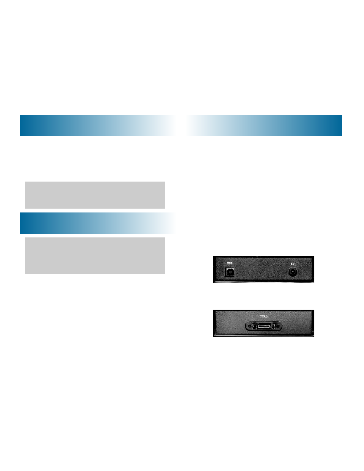
1. Place the USB560 JTAG Emulator module in desired location.
2. Connect the 5v DC power plug of the power supply to the
5-volt DC input on the USB560 JTAG Emulator (see figure
1).
3. Attach the USB cable to an available USB port on the PC
and to the USB connector on the USB560 JTAG Emulator
(see figure 1).
4. Attach the JTAG cable assembly to the corresponding “D”
connector of the USB560 JTAG Emulator (see figure 2).
5. Connect the power supply A/C wall cord to A/C power,
which will power the USB560 JTAG Emulator and initiate
Plug and Play installation for the Windows device driver
(see step 3 on USB PnP Installation).
FIGURE 1—USB & Power Endplate
FIGURE 2—JTAG End Plate
2 Hardware Installation
1. Insert the Emulation Driver CD.
2. Follow the installation wizard, and when done, you are
ready to install the emulator hardware.
NOTE:
If the installation executable fails to start automatically,
run X:\Demoshield\Setup.exe,
where [X] is the drive letter for your CDROM drive.
 Loading...