

BLACKHAWK! USB510W Quick Start Manual
1 4
5 CCStudio Setup
Blackhawk
123 Gaither Drive, Mt. Laurel, NJ 08054-1701
www.blackhawk-dsp.com
Blackhawk is a registered trademark of EWA Technologies, Inc.
USB510W-QSe-01
ETHERNET DEBUG INSTALL
This ETHERNET debug installation portion of the USB510W Quick Start Guide
series is intended to show how to configure the USB510W Emulator for operation
with Code Composer Studio using its LAN port.
For emulator debugging via the USB interface, please refer to USB Debugging Quick
Start Guide also included with the USB510W JTAG Emulator.
Inventory of Items Included
1. Blackhawk USB510W JTAG Emulator POD
(USB510W) and 8 inch JTAG cable.
2. High-Speed USB 2.0 Compliant Cable
3. 5 Volt USB power supply
4. 20e_cTI-14t_TI Pin Converter
5. 20e_cTI-20t_ARM Pin Converter
6. Installation CD
7. Warranty Card.
8. Quick Start Guide.
Other Items Required
1. Target Board System—a self-powered
board with a TI DSP and compatible JTAG
header connection conforming to IEEE
1149.1 Standard.
2. Copy of Code Composer Studio Version
3.3 †or later.
(Recommended CCSv4/5)
Installation Requirements
•
PC or Notebook computer with one free USB v1.1 or v2.0 port for USB debug or USB510W
administration and/or free Ethernet port for LAN debug†.
• Windows® 2000 or XP/Vista/Linux Operating System
• Texas Instruments Code Composer Studio Version 3.3 or later.
• CD-ROM Drive.
†
Ethernet connections to a local area network from the USB510W Ethernet port is made using a standard RJ45
patch cable (supplied). For direct connection (PC to USB510W ) an RJ45 cross-over cable is required (not supplied). USB510W administration of TCP/IP address and subnet mask is done via USB port on the emulator.
6 Quick Diagnostic
The USB510W is a network device, so when it is powered and connected to your network, you can use the
standard Windows PING command to test if the emulator is accessible from your PC. Just enter the command
shown below, which uses the default address. Your USB510W may be configured with a different address, so
check with your network administrator if you did not originally configure the device.
C:\>ping 10.0.9.1
QUICK
START
GUIDE
Blackhawk™
USB510W
JTAG
Emulator
(USB510W)
This equipment is designed to be
operated under the following environmental conditions:
Temperature between 0°C –55°C.
Relative Humidity of 20% - 70%
non-condensing.
Operation of the unit outside of the
above range may affect structual
and mechanical integrity and
cause permanent damage.
Caution is necessasry to minimize
ESD (Electro-stactic Discharge)
which can damage electronic
components. Use in a controlled
environment where ESD materials
and practices are employed is
highly recommended.
IMPORTANT
E
NVIRONMENTAL
C
ONSIDERATIONS
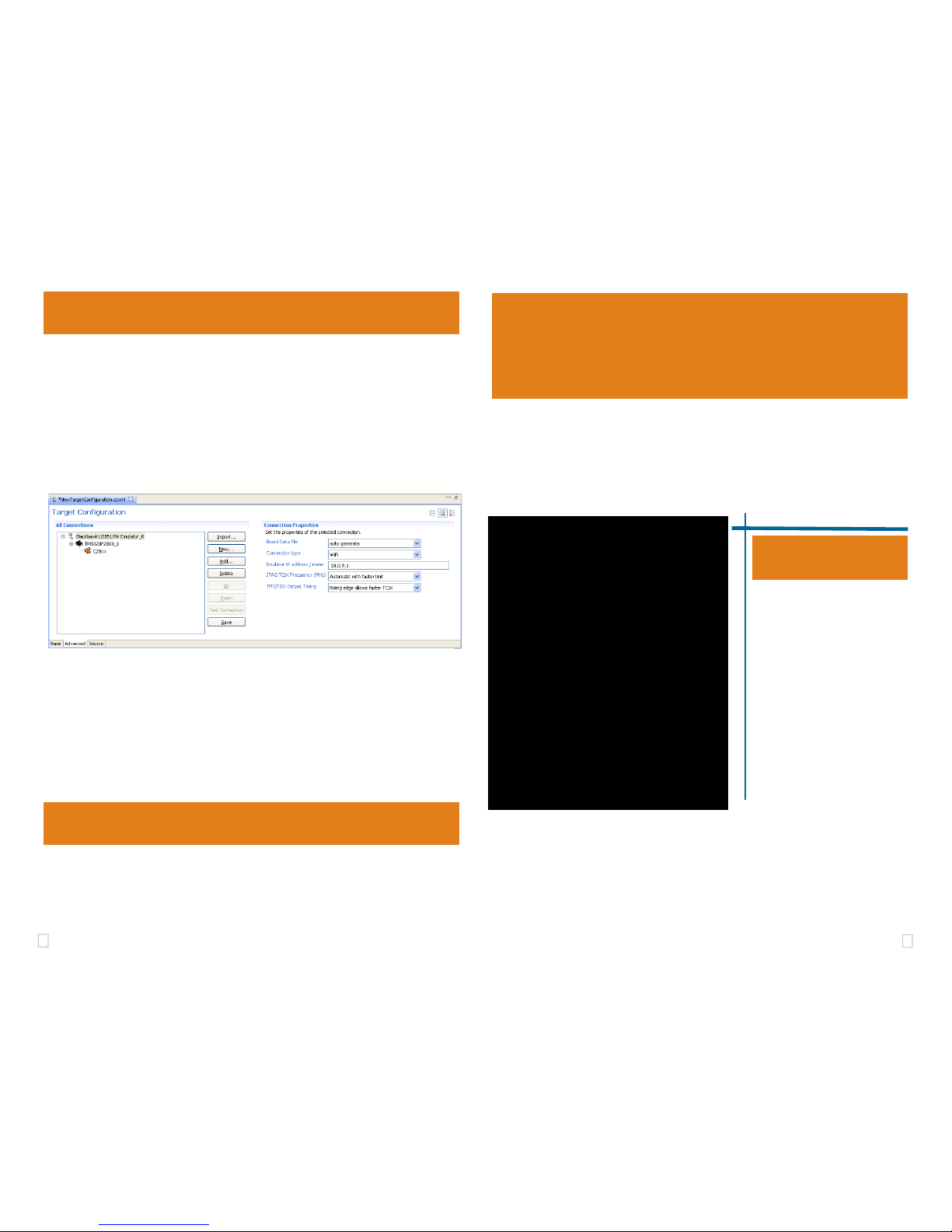
CCStudio v4 and later
1. In the CCS v4 or v5 bring up the New Target Configuration Win-
dow from the File Menu option.
2. From the connection drop down list select the Blackhawk USB510W
Emulator
3. Select your board or device that is connected to the emulator.
4. Choose the Advance properties tab.
5. Select “WiFi” in the Connection Type drop down.
6. Enter the Emulator’s IP address 10.0.9.1, if not already entered.
7. Save this setting and launch the TI Debugger.
FIGURE 5 - USB510W Target Setup and Selection
CCStudio v3.3 Service Release 12
1. Launch Setup Code Composer Studio v3.3.
2. From the platform drop down list select the bh-usb510(w) emulator.
3. From the family drop down list select your target device family .
4. Select your board or device from the middle pane and double click on it.
5. Right Click on the USB510W configuration and Choose Propertie s...
6. Go to Connection Properties Tab in the new dialog menu.
7. Select “WiFi” in the Connection Type drop down.
8. Enter the Emulator’s IP address 10.0.9.1, if not already entered.
9. Save & Quick the setting to launch Code Composer.
2
3
1 Emulation Driver Installation
Skip this step if you are using Code Composer v4 or later, and it is already
installed on your system
The USB510W Emulator shipped with its emulation drivers on CD ROM media
that are needed by Windows and Code Composer Studio v3.3 for operation.
2 Hardware Installation
1. Insert the Emulation Driver CDROM into your PC’s CDROM drive.
2. Follow the installation wizard, and when done, you can install the emulator hardware.
If the installation executable fails to start automatically, run X:\Setup\Setup.exe,
where [X] is the drive letter for your CD ROM drive.
Network Cofiguration 4
1. Place the USB510W module in desired location and connect the 5v USB mini B plug of the
power supply to the 5-volt DC input on the USB510W (see figure 1).
2. Attach the emulator’s JTAG cable assembly (the 20-pin, 2x10 JTAG connector shown in
figure 2) to the pin converter with corresponding header on the target board. Make sure the
target board is not powered when connecting!
If the USB510W is already installed on your network and connected to a target board,
you can skip this section and move to section 3.
WARNING
Be careful to connect interface cables with the correct orientation. Pin 1 on the inter-
face cable should match Pin 1 on the DSP system connector. The JTAG cable as-
sembly features a "keyed" connector to minimize the chance of error.
Make sure the target is not powered when connecting!
3 Ad-Hoc Create Mode Setup
The default WiFI setup for the USB510W is “Ad-Hoc Create”. This will allow a computer to join to the USB510W network.
1. From your windows Start button, choose , choose: Start > Settings > Control
Panel > Open Windows Network connections
2. Right Click on the Wireless Network Connection, and choose properties, which will
display the network properties dialog.
3. Highlight “Internet Protocol (TCP\IP)” entry and click the properties button
4. In the dialog, configure the settings to IP 10.0.9.2, Subnet Mask 255.255.255.0
You should record your current settings to return them back to their original settings later.
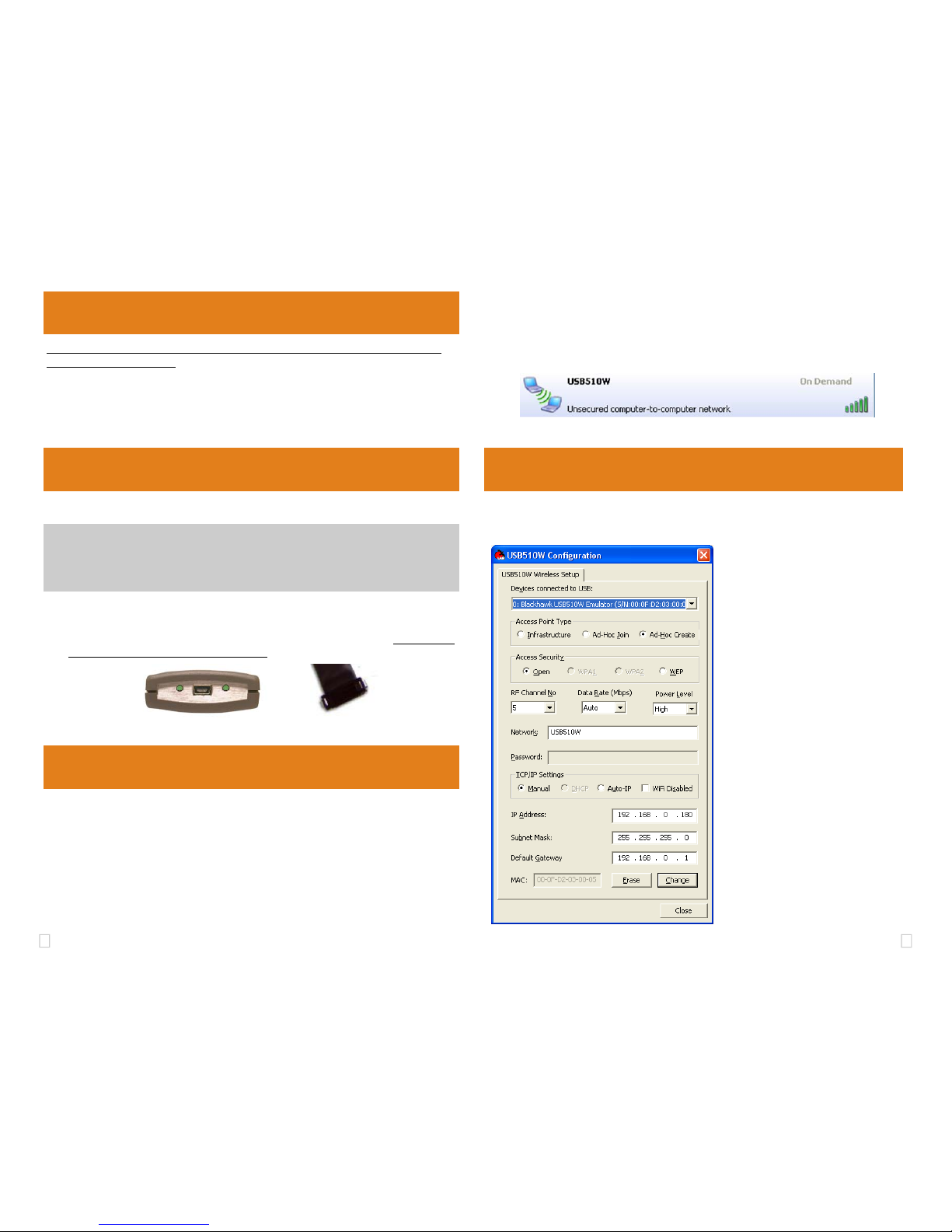
• This section describes how to customize the USB510W configuration
• Launch the USB510W Configuration utility from windows desktop shortcut
FIGURE 4—USB510W Configuration Utility
FIGURE 2— 20-pin JTAG End FIGURE 1— WLAN,USB &
Power Endplate
5. Using the Windows wireless network connection, you can search for available Wireless Networks. You should see the USB510W-<serial> SSID as shown in figure 3.
6. Select the entry and choose connect. If you see Acquiring network address for more
than few seconds, go back check you’re IP settings for the USB510W and your PC’s wireless adapter TCP/IP settings.
FIGURE 3—USB510W AD-HOC SSID
• Select your USB510W to be con-
figured from the drop down menu
• Choose the Access Point Type you
wish to use with the
USB510W
• Select the Access Security Type you
wish to use with your
USB510W or is
configured on your network
• Optional—Set the RF channel Num-
ber, The
USB510W WiFi Data Rate,
and the
USB510W WiFi antenna
Power level
• Type in the SSID for the Emulator to
be connected too if you chose Infrastructure/Ad-Hoc Join modes, or the
SSID the emulator will broadcast if you
chose Ad-Hoc Create Mode.
• Type in the Password for your network
if a Access Security option is not open.
• Setup the IP setting the emulator will
use that bet matches your network, for
Ad-Hoc mode it is recommended to
use Manual static IP settings.
 Loading...