

BLACKHAWK! USB100v2 Quick Start Manual
1 4
Blackhawk™
USB100v2
JTAG
Emulator (USB100v2)
QUICK
START
GUIDE
XDS100v2 JTAG Emulators Require:
Code Composer Studio v4 or later
†
Install CCSv4 before connecting XDS100v2 hardware!
You will also need:
PC or Notebook computer with at least one free USB v1.1 or v2.0 port.
Windows® 2000/XP/Vista/7 Operating Systems (32 or 64-bit versions).
Inventory of Items Included
1. Blackhawk USB100v2 Emulator.
2. USB 2.0 Compliant Cable.
3. Warranty and Product Registration
Cards.
4. Quick Start Guide.
Other Items Required
1. Target Board System — a selfpowered board with a TI DSP and
compatible JTAG header connection
conforming to IEEE 1149.1 Standard.
2. Copy of Code Composer Studio v4†
or later.
† CCStudio v4 is available for download from TI for use with XDS100 products
free-of-charge. Please visit this TI Wiki page for more information:
http://tiexpressdsp.com/index.php/CCSv4.
4 CCStudio v4 Setup
This equipment is designed to
be operated under the following environmental conditions:
Temperature between 0°C –
55°C. Relative Humidity of
20% - 70% non-condensing.
Operation of the unit outside of
the above range may affect
structual and mechanical
integrity and cause permanent
damage.
Caution is necessasry to
minimize ESD (Electro-static
Discharge) which can damage
electronic components. Use in
a controlled environment
where ESD materials and
practices are employed is
highly recommended.
IMPORTANT
ENVIRONMENTAL
CONSIDERATIONS
Blackhawk
123 Gaither Drive, Mt. Laurel, NJ 08054-1701
www.blackhawk-dsp.com
Blackhawk is a registered trademark of EWA Technologies, Inc.
USB100v2-QS-01
Follow these links for more details on XDS100v2 setup using CCStudio v4:
http://tiexpressdsp.com/index.php/CCSv4.
http://tiexpressdsp.com/index.php/Target_Configuration_-
_Custom_Configurations
Additional XDS100v2 Information
Follow this link for more details and support on the XDS100 product:
http://tiexpressdsp.com/index.php/XDS100.
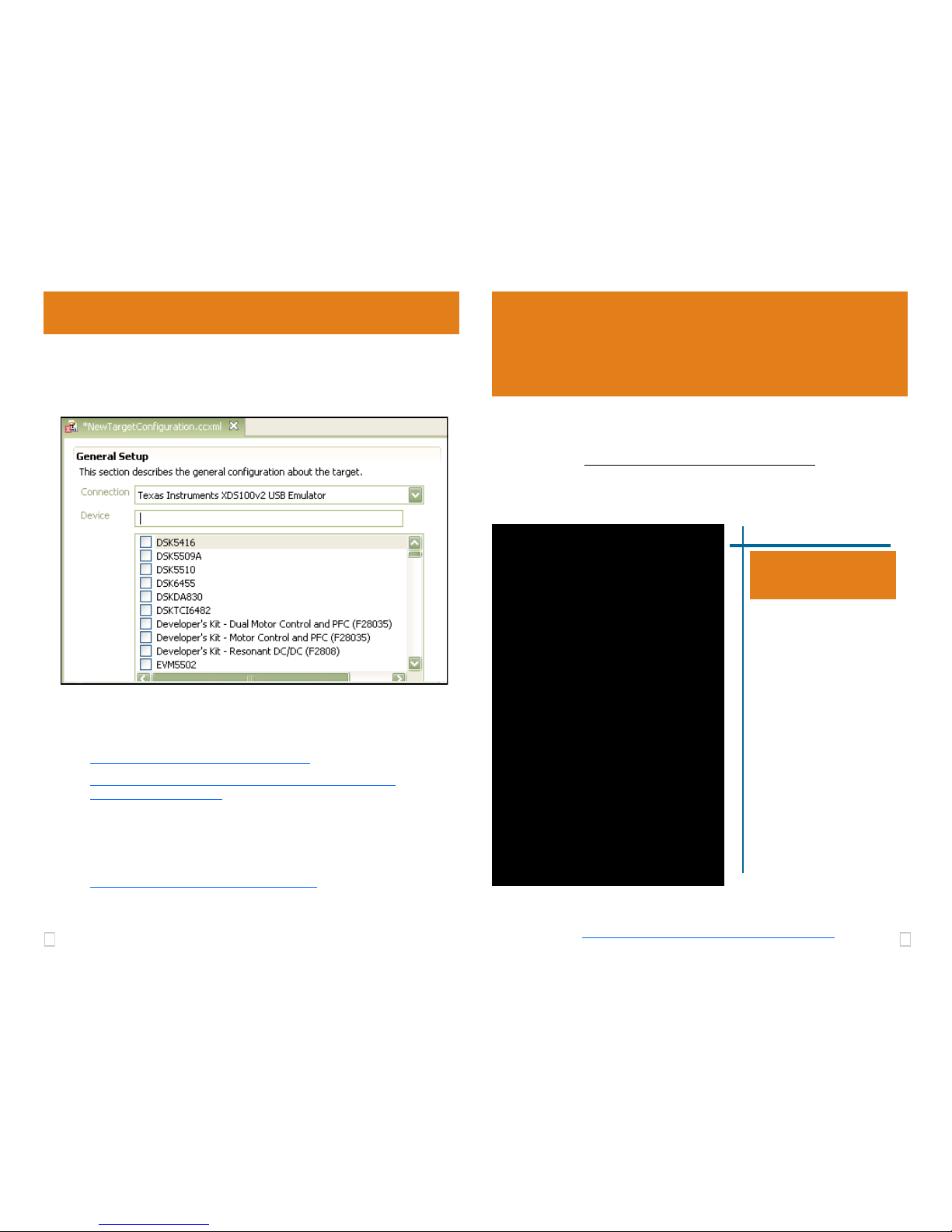
In the CCSv4 Target Configuration General Setup window (see figure 2
below) simply select the Texas Instruments XDS100v2 USB Emulator
connection and then check your device or board in the list. Save this setting and launch the TI Debugger.
FIGURE 2 - XDS100v2 Target Setup and Selection
3 2
USB PnP Installation 3
1. Install Code Composer v4 software FIRST. DO NOT ATTACH EMU-
LATOR HARDWARE UNTIL CCSv4 IS INSTALLED.
2. Complete step 1, then attach the USB cable to an available USB port on
the PC.
3. Then attach the other end of the USB cable (female A connector) to the
USB A male connector of the USB100v2 Emulator (see Figure 1).
4. Follow the Plug and Play installation for the Windows device driver (see
section 3 on USB PnP Installation for more information).
5. If your target uses a 14-pin (2x7) header, attach the 14-pin socket to
your target (see figure 1). If your target has a cTI 20-pin header, connect the 20-pin cTI socket.. Make sure the target board is not powered
when connecting!
6. Setup and start Code Composer Studio (see section 4)
1 Emulation Driver Installation
2 Hardware Installation
W A R N I N G
Be careful to connect interface connector with the correct orientation.
Pin 1 on the interface cable should match Pin 1 on the DSP system
connector. The JTAG connection features a "keyed" connector to mini-
mize the chance of error.
Do not force connector into position. Forcing them may damage the
connector or the interconnected boards and systems.
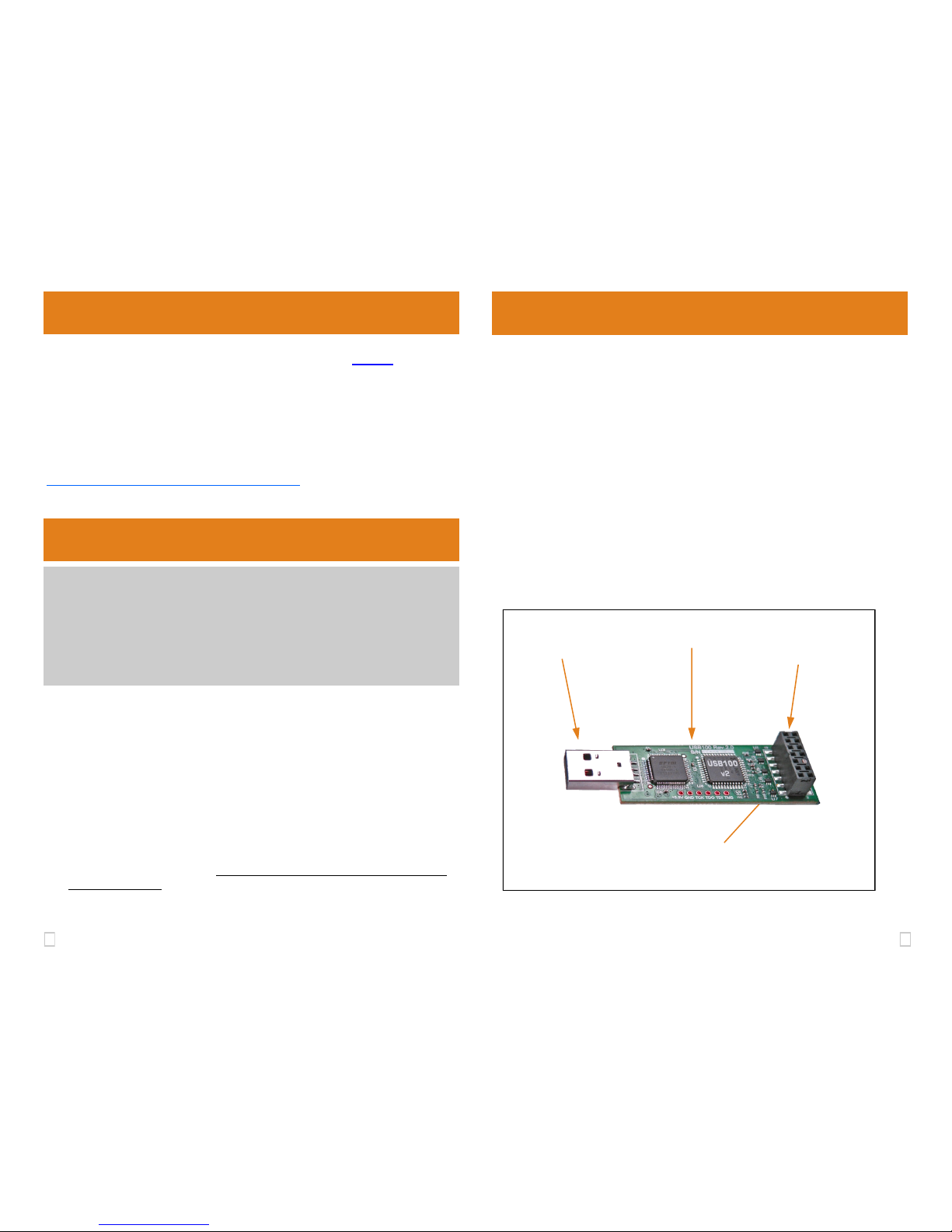
FIGURE 1 - USB100v2 JTAG Emulator
Windows 2000/XP/Vista/7
1. Install Code Composer Studio v4 FIRST. DO NOT ATTACH EMULATOR
HARDWARE UNTIL CCSv4 IS INSTALLED.
2. Complete step 1, then if not already connected, connect the USB cable
to the computer and to the USB100v2 emulator.
3. If prompted, follow the Windows ―Found New Hardware‖ wizard prompts.
4. You can select the ―automatic‖ option for locating drivers.
5. When completed, Windows Device Manager will show the device under
the Universal Serial Bus controllers as TI XDS100 Channel A and TI
XDS100 Channel B.
6. Now follow the Code Composer Studio Setup—Section 4
Code Composer Studio v4 Must be Installed FIRST
XDS100v2 Drivers are installed as part of CCS v4 or CCS v4 update. By
default, the drivers are installed to the following folder:
C:\Program Files\Texas Instruments\ccsv4\common\uscif\ftdi
For more information on CCS v4, refer to the TI documentation and help resources and the following link:
http://tiexpressdsp.com/index.php/CCSv4
XDS100v2 PCB Assembly
(small 22 x 40 mm)
USB A
Connector
cTI 20-pin keyed JTAG Connector
(under PCB, not visible here)
TI 14-pin keyed
JTAG Connector
 Loading...