

BLACKHAWK! STL27, STL28, STL2710, STL2810, STL2820 Instruction Manual
...
ELECTRO-HYDRAULIC
VEHICLE LIFT
STL27- STL28
STL2710 - STL2810
STL2720 - STL2820
STL2730 - STL2731 - STL2733
(
Lifts from serial nb 0212-705-0009 &)
(Pumps from serial nb 0212-706-0009 & )
INS
STL27GB
REV: 06 2014
INSTRUCTION MANUAL
(original manual)

STL27 – STL28
INDEX
Page no
I) CAUTIONS - SAFETY INSTRUCTIONS 3
II) INTRODUCTION 7
III) PACKAGING, TRANSPORT AND STORAGE 7
IV) GENERAL DESCRIPTION 9
V) TECHNICAL SPECIFICATIONS 10
VI) FOUNDATION WORK (in floor versions) 11
VII) INSTALLATION 12
VIII) MAINTENANCE 21
IX) SPARE PARTS 22
X) HYDRAULIC CIRCUIT 23
XI) PNEUMATIC CIRCUIT 24
XII) ELECTRICAL CIRCUIT, versions (STL 27 - 28 – 2710 - 2810-2730-2731-2733) 25
XIII) ELECTRICAL CIRCUIT, ATEX versions (STL 2720 - 2820) 27
XIV) EXPLODED VIEWS OF PLATFORMS, versions (STL 27- 2710- 2720) 29
XV) EXPLODED VIEWS OF PLATFORMS, versions (STL 28 - 2810-2820) 30
XVI) EXPLODED VIEWS OF PLATFORMS telescopic arms versions (STL2730-2731) 31
XVII) EXPLODED VIEWS OF LIFTS, versions (STL 27-28-2710- 2810-2730-2731-2733) 32
XVIII) EXPLODED VIEWS OF LIFTS, ATEX versions (STL2720-2820) 34
XIX) EXPLODED VIEWS OF PUMPS, versions (STL 27 - 28 - 2710 - 2810 - 2730- 2731-2733) 36
XX) EXPLODED VIEWS OF PUMPS, ATEX versions (STL 2720 - 2820) 37
XXI) EXPLODED VIEWS valve block, all versions (STL27-28-2710-2810-2720-2820-2730-2731-2733) 38
XXII) DECLARATION OF CONFORMITY 39
XXIII) MAINTENANCE BOOKLET 40
2
STL27 – STL28
I) CAUTIONS - SAFETY INSTRUCTIONS
The contents of this user manual only concern aspects relative to operation and to safety when installing the equipment.
To fully understand the terminology used in this manual, the person in charge of the installation should have specific
experience in production, service, maintenance and repair in an industrial environment, and have the competence to explain
the contents of the diagrams and descriptions to other people. Moreover, this same person should have knowledge of the
general and specific regulations covering safety applicable in the country where the lift is installed.
SAFETY
It is important to read this paragraph carefully as it contains important information on the risks to which the operator exposes
himself / herself by using the lift incorrectly. Please find hereafter the information to enable the user to avoid dangerous
situations.
WARNING
This lift was designed to lift vehicles up and to maintain them in a specific position in a covered workplace.
Any other use is forbidden
In short, the lift is not suitable for the following uses:
- washing and spraying operations
- use as traction equipment
- use as a goods lift
- use in an area where there is a danger of explosion (spray booths, etc), except for special versions. (ATEX)
The floor on which the lift is placed should be sufficiently strong to support the weight of the lift, the load deck and the load,
with a safety margin of 25%;
The concrete floor must have a minimum thickness of 150mm and a minimum resistance of C20/25 (Norm EN206-1)
Any masonry work required should be studied by a design office and carried out by a masonry company, authorised to carry
out such work and projects.
The lift can be recessed into the floor (refer to the drawings covering the foundation works). The lift must be fixed using the
"rawlplugs" provided or equivalent anchors.
The manufacturer will not take into account any request for compensation for injury or material damage (vehicle or other
goods) in the event of improper and / or unauthorised use of the lift.
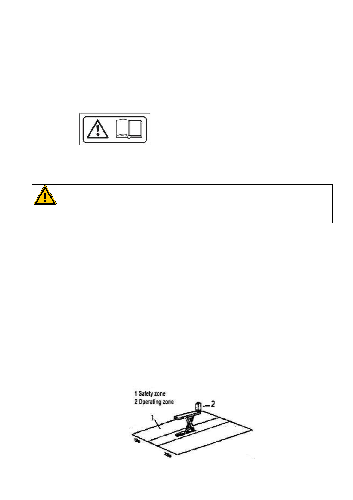
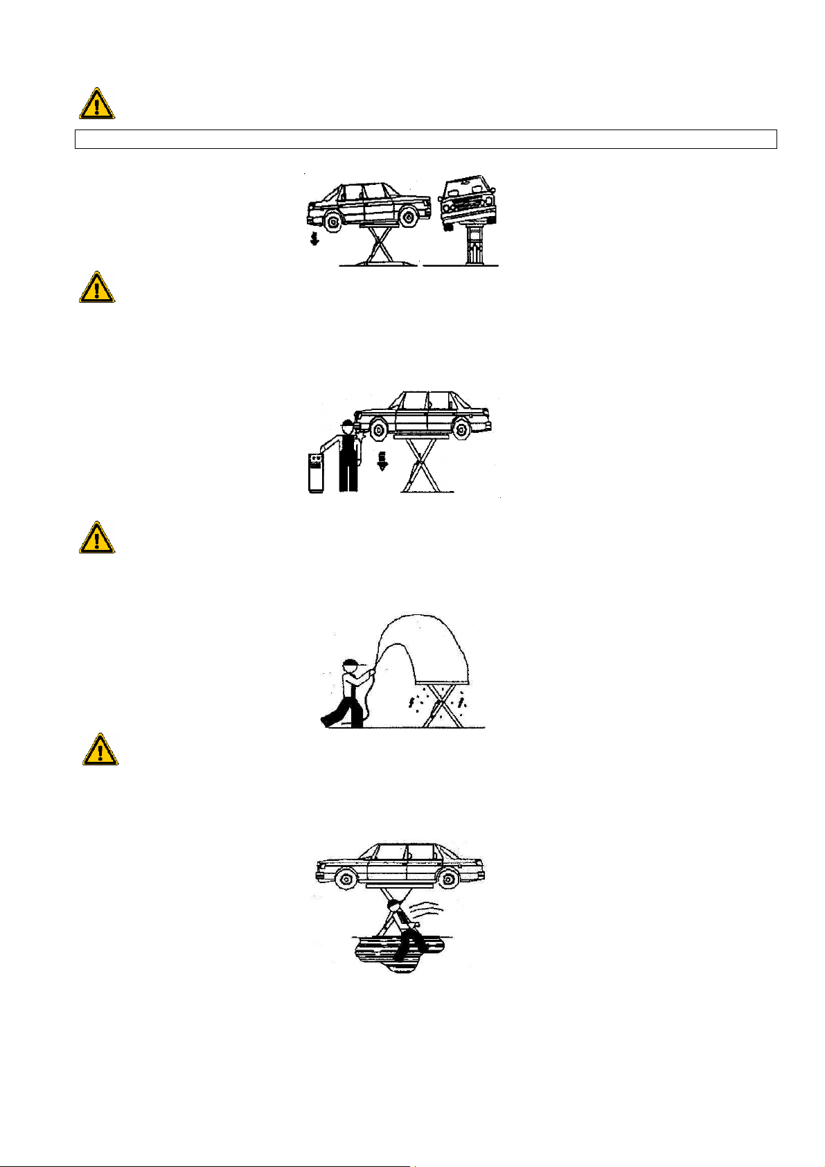
During raising and lowering the operator must remain inside the operating area (2) as defined in Figure 1. Entry into the
safety area (1) is strictly forbidden. The presence of a person under the vehicle is only authorised when the lift is in its fully
raised position.
Figure 1
3
STL27 – STL28
During lifting the operator should ensure that the load does not present any risk; after raising the vehicle a small amount he
should stop and check that it is correctly positioned before continuing.
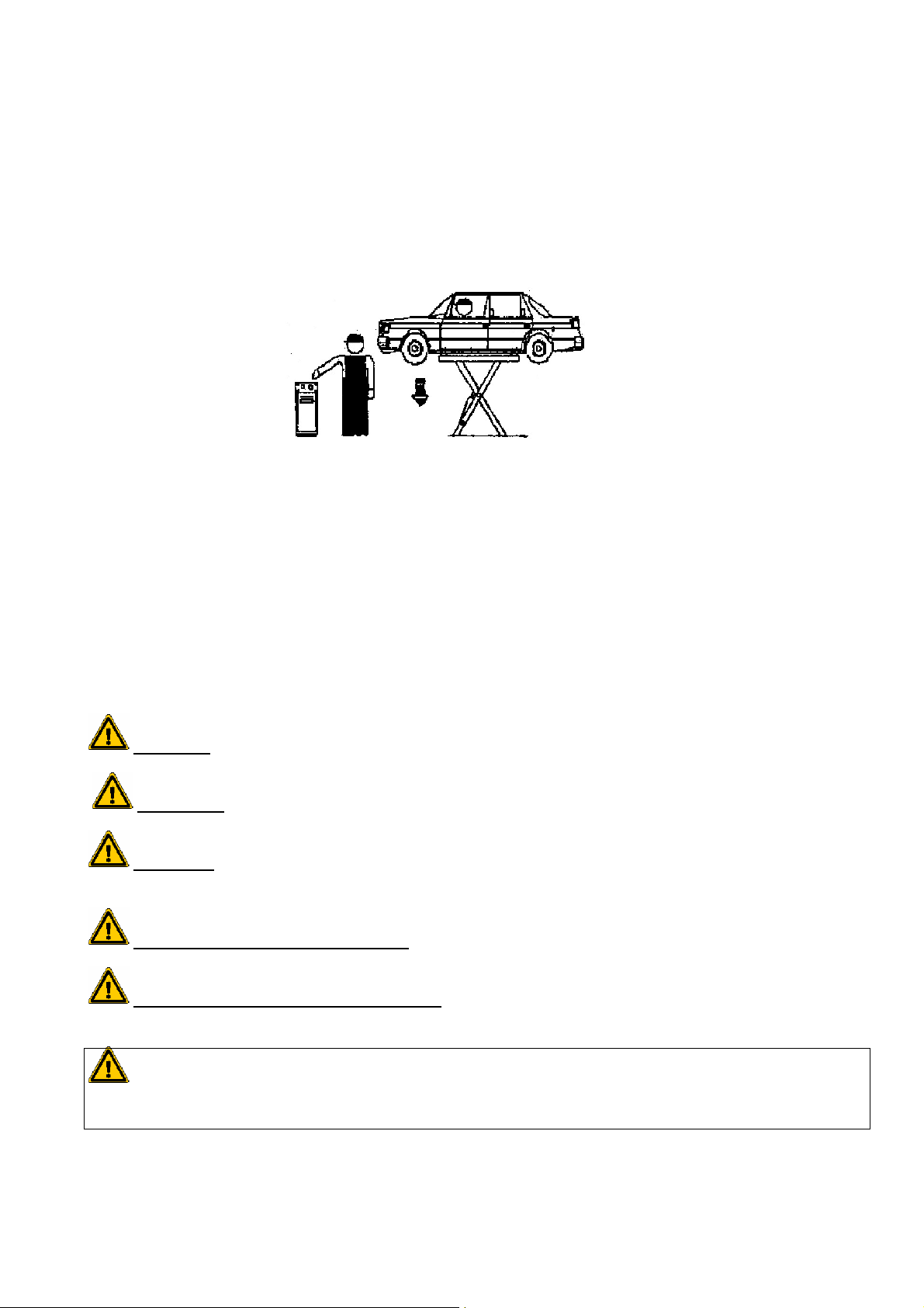
THE OPERATOR should check the load and the loading platform during raising and lowering.
It is forbidden to climb on the load or the loading platform when they are raised.
Never start the vehicle when it is raised, even a little, or before the lift is completely lowered.
Figure 2
Never use the lift unless all the safety systems are working properly. Failure to follow these rules may result in serious injury
or irreparable damage to the vehicle lift and / or to the vehicle placed on it.
GENERAL PRECAUTIONS:
- The operator must follow the regulations in force in the country in which the lift is installed.
In addition, the operator must:
- Always work in the operating area in accordance with the instructions in the manual.
- Never remove the protective covers or dismantle or close the mechanical, electrical or other safety systems.
- Read the safety regulations applying to the lift and the safety instructions in the manual.
The following terms are used in the manual to describe the types of risk:
DANGER
to the lift, the vehicle or other goods
WARNING
CAUTION
RISK OF ELECTRICAL DAMAGE
: for the possibility of a risk that could cause serious injury or death
: describes situations and / or actions that could cause injury or but not death
: describes situations and / or actions that are dangerous and likely to cause slight injury and / or damage
:
the lift has specific safety equipment installed in areas of high risk.
RISK AND MEANS OF PROTECTION
in the raised position, and the means of protection installed to minimise any dangers.
WARNING
Do not move the vehicle when raised on the platform. Remove the platforms and the rubber accessories only when
the lift is in the lowest position and not loaded.
:
these are risks to which the operator is exposed when the vehicle is
4
STL27 – STL28
The vehicle should be positioned on the lift so that the load is evenly distributed over the platform.
SAFETY DEVICES
The following safety devices are installed to prevent damage or overloading:
- DEAD MAN SYSTEM
The lift is fitted with "dead man" type controls. Raising and lowering movements, controlled by push buttons, stop immediately
if the button is released.
- FOOT PROTECTOR
A safety device that automatically stops the movement approximately 20 cm from the floor.
- A SELF-REGULATING FLOW LIMITER THAT CONTROLS DESCENT SPEED
- SAFETY SOLENOID VALVES
A dual hydraulic circuit comprising 3 solenoid valves
- PRESSURE RELIEF VALVE
An excessive load on the lift causes the pressure relief valve to open.
- MOTOR THERMAL PROTECTION
Cuts off the power supply in the event of an overload.
RISKS FOR PERSONS
This paragraph describes the risks to which the operator, or any other person in the vicinity of the operating area, is exposed
by inappropriate use.
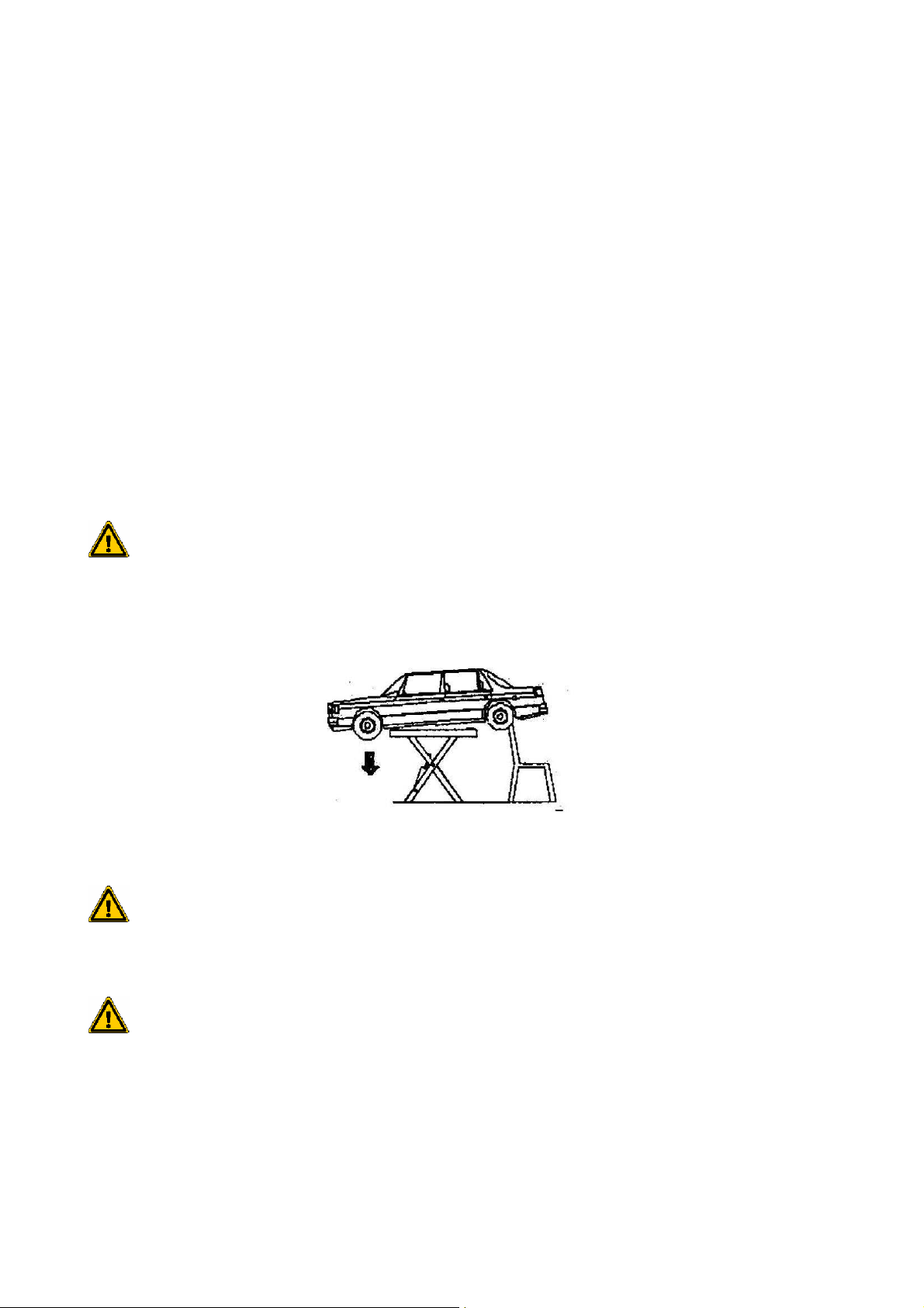
Never leave accessories or other objects against the platform and never place objects on the platform when it is loaded, as
this could hinder the operation of the lowering mechanism, and possibly cause the vehicle to fall (Figure 3).
figure 3
Blackhawk uses the highest quality materials for its lifts to guarantee their safety. They should be used in accordance with the
specified criteria and be regularly maintained.
RISKS LINKED TO USE AND MAINTAINANCE
Blackhawk uses the highest quality materials for its lifts to guarantee their safety. They should be used in accordance with the
specified criteria and be regularly maintained.
RISKS LINKED TO THE POSITION OF THE VEHICLE
This type of risk can arise if the vehicle is not properly positioned on the rubber pads (Figure 4), or if the platforms are not
correctly aligned in relation to the vehicle. Always use the lift points specified by the vehicle manufacturer and position the
vehicle as close as possible to the centre of the platform.
5
CAUTION
STL27 – STL28
Please note that the ratios of weight distribution change when heavy components are removed (for ex.: engine, axle)
Figure 4
RISK FOR THE OPERATOR
The risk occurs if the operator does not to stay in the appropriate place next to the pump. The operator MUST NOT remain
under the moving system when the lift loaded with a vehicle is descending. It is ESSENTIAL that the operator remains in the
operating area during raising and lowering. (Figure 5)
Figure 5
RISK OF ELECTROCUTION
Never spray water or solvent or paint vapour, near the platform or the control console. (Figure 6)
This risk can be controlled by taking care not to spill oil or grease in the area near the lift. In any event, it is essential to
thoroughly clean any area where oil has spread. (Figure 7)
RISK OF SLIPPING
Figure 6
Figure 7
6
STL27 – STL28
II) INTRODUCTION
CAUTION
This installation manual is destined for qualified bodyshop personnel used to working with lifts, and the technicians
who are in charge of the installation and maintenance of he lift.
This manual is essential to the use of the lift, and as such should be kept in an easily accessible place for consultation. We
advise giving special attention to the chapter dealing with safety.
This manual is an integral part of the vehicle lift and should always accompany it, even in the event of resale.
Only qualified and authorised personnel may operate the lift. This applies especially to transport, assembly, installation,
maintenance, overhauling, moving, dismantling, etc. The manufacturer cannot be held responsible for damage caused to
persons, vehicles or objects in the event of inappropriate use of the lift.
Lifts are designed and built according to the following standards:
- European Directives: 2004/108/EC – 2006/42/EC – 2006/95/EC
- European standards: EN1493 / EN ISO 12100/1 / EN ISO 12100/2 -Electrical standards: EN 60204/1
III) PACKAGING, TRANSPORT AND STORAGE
CAUTION
Operations to do with working, unpacking and transport of the equipment should be carried out exclusively by
qualified personnel having a good knowledge of the use of the lift and its manual
HANDLING THE EQUIPMENT IN ITS PACKAGING
The boxes should be lifted and moved with a fork lift truck or a crane. (Figure 8).
The means used must be suitable for safe handling, considering the size, weight, centre of gravity, protruding parts
and fragile components which must not be damaged.
The overall weight of the package is approximately 400 kg.
The weight of the oil pump delivered separately on a pallet is approximately 40 kg
7
Figure 8
STL27 – STL28
STORAGE
The lift in its packaging should always be stored in a covered and protected place at a temperature between – 10°C + 40°C
and protected from direct sunlight.
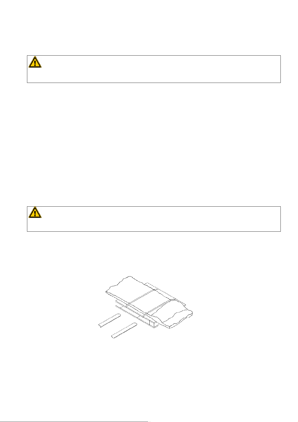
TRANSPORT- STACKING BOXES
The type of packaging used allows up to 5 lifts to be stacked on top of one another, provided they are correctly positioned
and are in no risk of falling. The boxes must only be stacked with wooden battens between them, never directly one against
the other. The boxes should be properly lashed during truck or container transport. Oil pumps are dispatched vertical on a
pallet; they must not be stacked or laid on their side, as damage could result.
OPENING THE BOXES
On receipt check that the equipment has not suffered any damage during transport and that all the items mentioned on the
packing list are present. Any damage or missing part must be reported to the carrier immediately, and then to the
manufacturer with the appropriate proof.
Proceed with the utmost care to avoid damaging the oil pump or the control console.
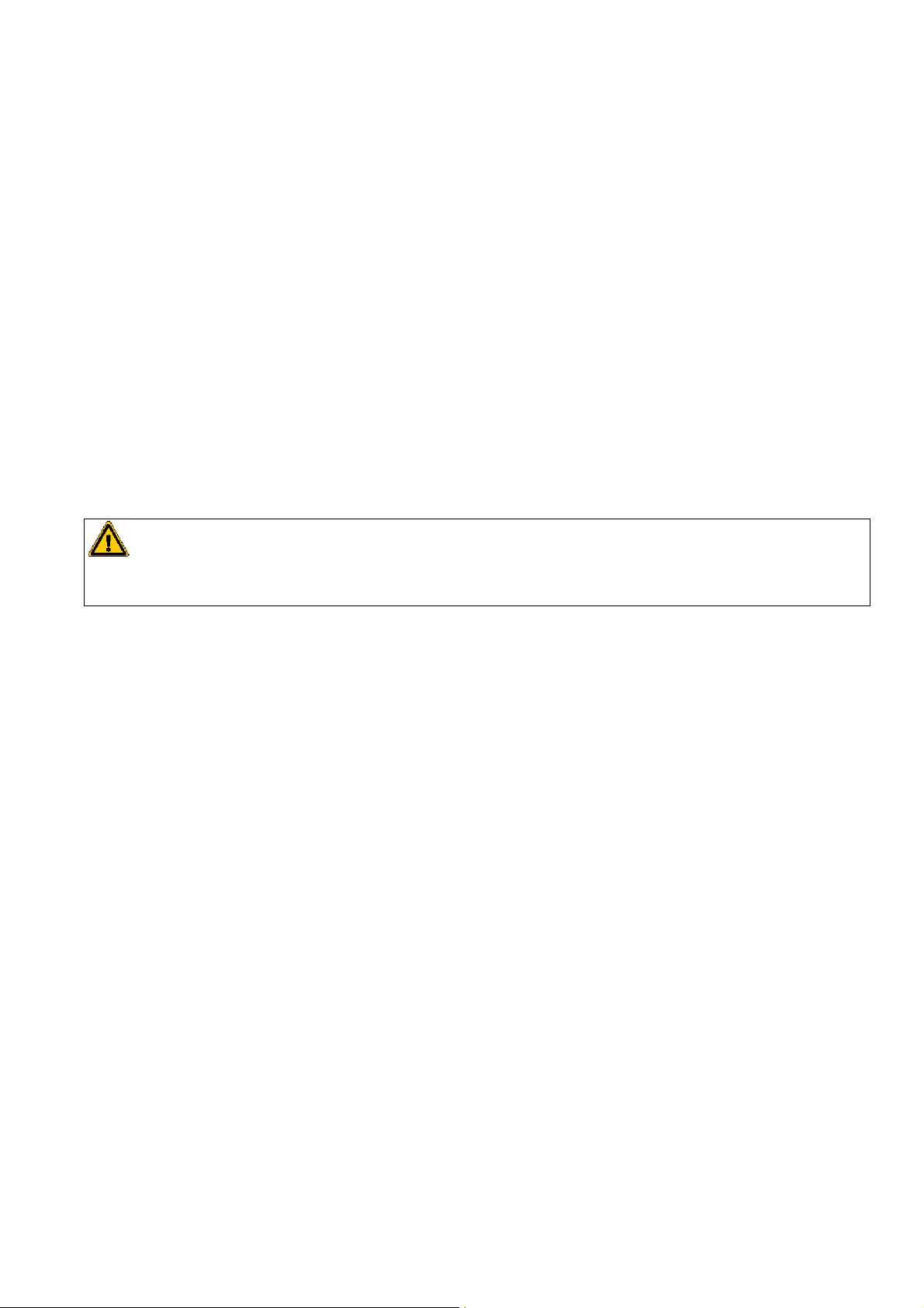
CAUTION
It is highly recommended to read the safety instructions before using the lift
DISPOSAL OF PACKAGING
The wood from the pallet can be reused or recycled; the shrink film should be disposed of in accordance with the standards
and regulations covering the recycling of plastics in force in the country where the lift is installed.
8
STL27 – STL28
B5
IV) GENERAL DESCRIPTION
The electro-hydraulic lift is installed on the floor or recessed into a pit. It is designed and built for lifting automobiles and
holding them in the raised position. The main parts of the lift are:
- Platform
Figure 9: detail of the parts comprising the lift
Base
- Scissors
This is the moving part of the lift which enables the lifting process to take place. It consists of a series of internal and external
arms connected by a coupling joint.
-
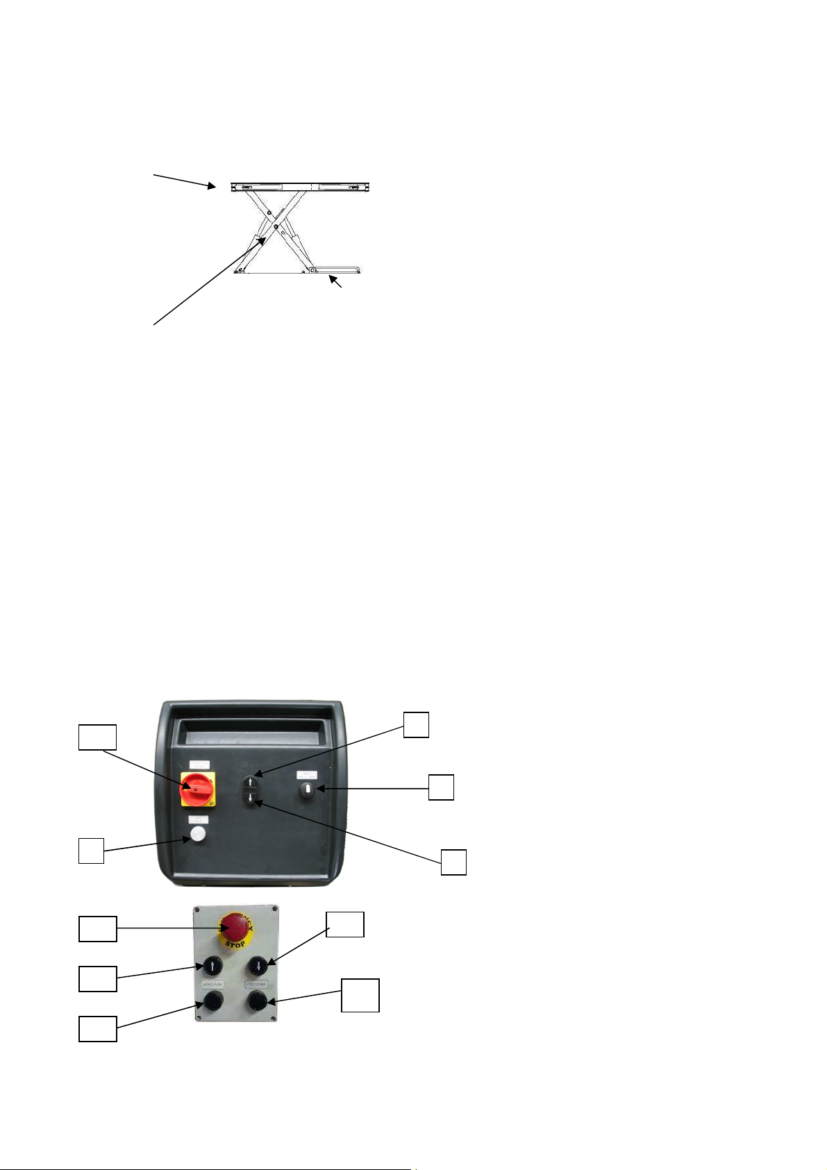
Control unit
The unit consists of a box containing all the lift control components - electrical, hydraulic (and pneumatic depending on the
version).
1. Main switch.
2. Indicator light: power supply light.
3. “Up” button. (Only on versions STL 27-STL 28-STL 2710-STL 2810).
4. “Down” button. (Only on versions STL 27-STL 28-STL 2710-STL 2810).
5. Arm open / close selector. (Only on versions STL 28-STL 2810).
B1 Emergency stop button (only on versions STL 2720-STL 2820).
B2 “Up” button (only on versions STL 2720-STL 2820).
B3 “Down” button (only on versions STL 2720-STL 2820).
B4 Arm opening button (only on version STL 2820).
B5 Arm closing button (only on version STL2820)
.
Figure 10
Figure 10a
9
STL27 – STL28
V) TECHNICAL SPECIFICATIONS
Pay load: 3500 kg
Lift weight: 400 kg
Noise level: 73.3 dB
Working temperature: -10°C / +50°C
Electric motor: 1.1 kW
Voltage: 230/400V, 3-phase
Frequency: 50 Hz
Control circuit: 24VDC
Oil pressure: 280 bars max.
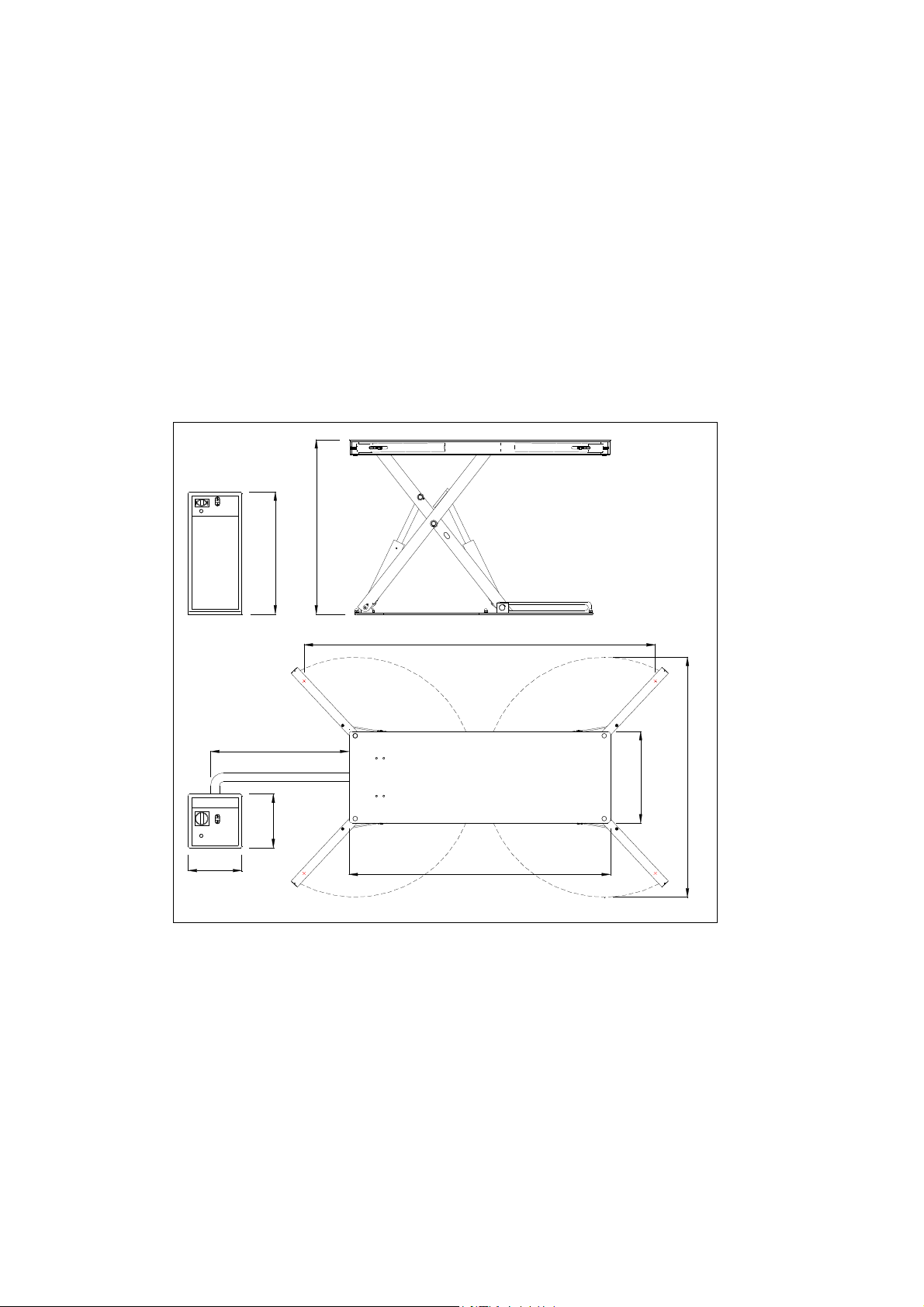
Dimensions:
0
0
2
1
x
a
M
0
0
1
4
1
8
n
i
M
2270
MAX 3500
0
7
3
370
1800
Versions:
• STL27: Above floor lift with manual arm opening.
• STL2710 : In floor lift with manual arm opening.
• STL28: Above floor lift with pneumatic arm opening.
• STL2810 : In floor lift with pneumatic arm opening.
• STL2720 : In floor lift with manual arm opening - ATEX version.
• STL2820 : In floor lift with pneumatic arm opening - ATEX version.
• STL2730 : In floor lift with telescopic arms and remote control.
• STL2731
:
In floor lift with telescopic arms.
• STL2733 : Above floor lift with telescopic arms and remote control
0
3
6
0
5
6
1
Figure 11
10
STL27 – STL28
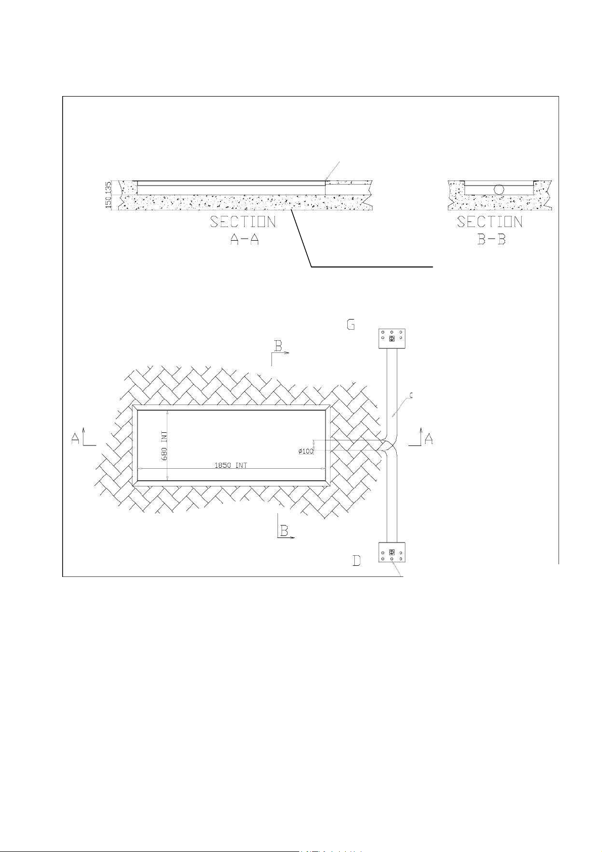
Strength of concrete C20/25
Angle 50x50x3
Hose D=100mm L=3500mm MAXI
Position of the control unit on the right (D)
VI) FOUNDATION WORK (in floor versions)
(Norm EN 206-1)
Figure 12
CONSTRUCTION TOLERANCE: +/-0,5cm
The bottom of the pit must be comfortably able to support the load and the load support. (~4000KG) Use diagonal checking to
confirm that the bottom of the pit is perfectly flat, horizontal and level with a maximum tolerance of 3mm.
Check that the concrete is fully dry before fixing the lift.
11
STL27 – STL28
VII) INSTALLATION
CAUTION
The elevator should only be installed and set up by qualified and authorized personnel
INSTALLATION PROCEDURE
1. Checking the electricity supply
First, make sure that the power supply is fitted with a magneto thermal protection switch (380V – 16A with a protective fuse)
and appropriate protection devices conforming to the electrical safety regulations in force.
2. Positioning the lift
When installing the lift take into account the size of the vehicles to be lifted, and a minimum distance of 500 mm between the
walls and the lift.
- Sufficient space for the operators.
- Sufficient space for maintenance and for entry and exit routes.
- Positioning in relation to other machines.
- Position of the console unit at a minimum 3m from the lift.
- The position of the console should allow the operator to observe all the movements of the lift.
Use a fork lift truck, crane or other appropriate lifting means to position the lift.
If the lift is being installed in a pit, make sure that the lift is correctly centred in the pit. If the floor is not level (up to 3mm), fill
the gaps with metal shims.
3. Anchoring the lift
The minimum resistance of the concrete floor the lift is installed on must be C20/25, and the minimum
thickness 150mm.
Use all the bolts supplied to fix the lift to the floor
• Using the base as a template, with a Ø 16 mm drill, make a hole in the floor to a depth of approximately 120 mm.
• Clean the holes and insert the 8 "rawlplugs" supplied, using a hammer but without hitting them hard.
• Before tightening the rawlplugs finally, check the perpendicularity between the vertical axis of the lift and the floor.
• Tighten the rawlplugs with a torque wrench (tightening torque 50 Nm).
3. Connections to the lift
WARNING
Before any work on the control unit to make electrical connections or repair faults, make sure that the power is
disconnected to prevent any danger of electrocution.
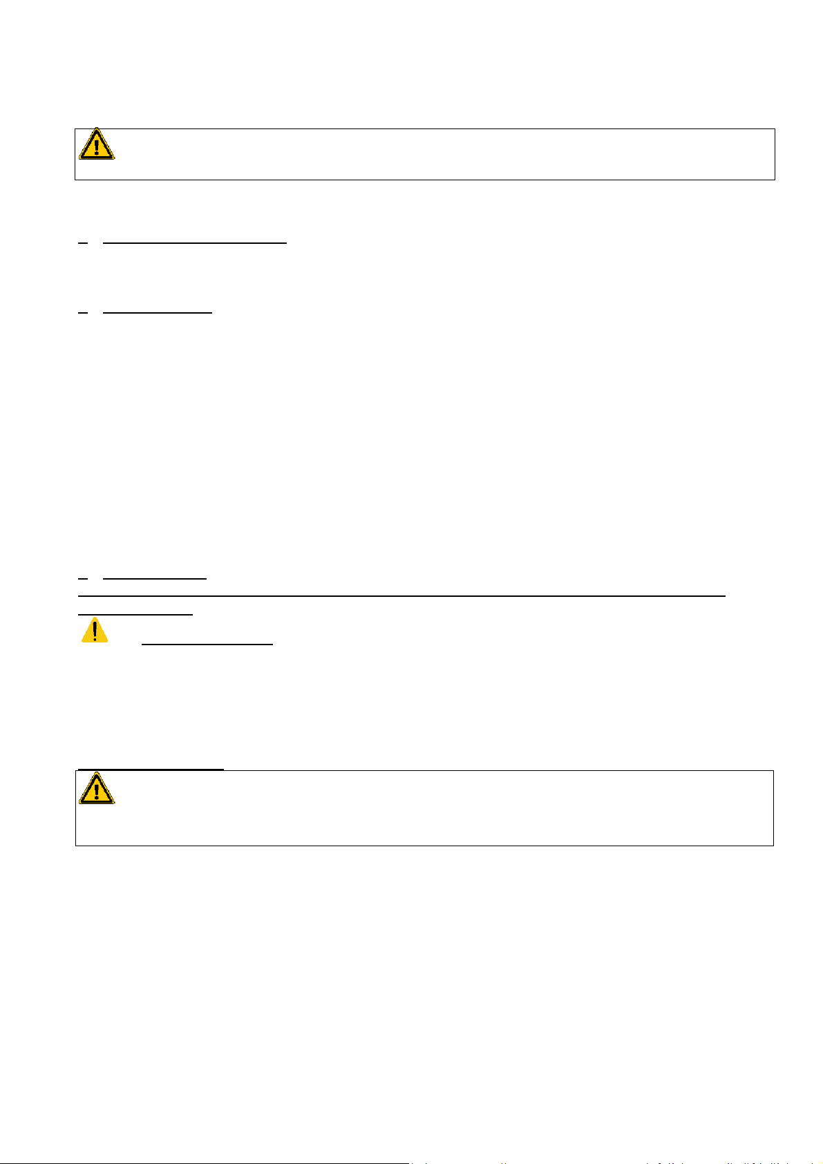
The lift has 3 adjustable limit switches F1, F2, F3. (Figure 17)
Limit switch F1 has the function of protecting the feet; it stops the platform descent at approximately 200mm from the floor
Limit switch F2 has the function of stopping the ascent of the platform approximately 10mm from the floor (in floor versions) to
allow the arms to be opened.
Limit switch F3 has the function of stopping the descent of the platform approximately 10mm from the floor (in floor versions)
to allow the arms to be closed
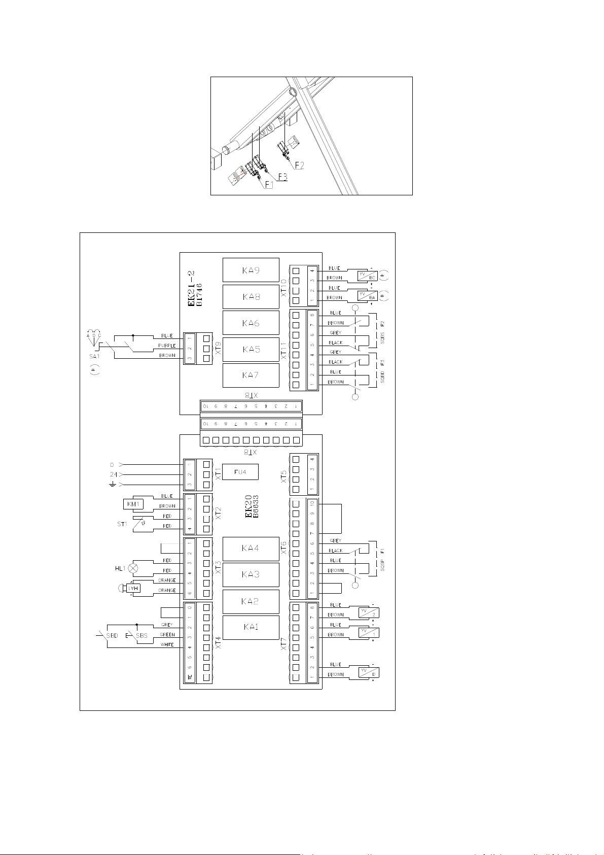
Set the main switch to 0, open the console covers and connect the limit switch cables from the lift as shown on the electrical
diagram. (Figure 18)
12
STL27 – STL28
(*) only
on
STL28 and STL2810
versions)
Figure 17
Figure 18
-
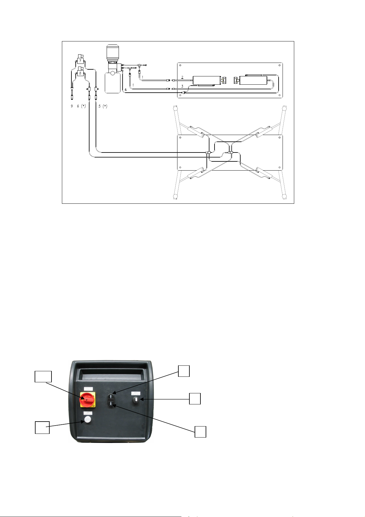
Make the hydraulic (and pneumatic, depending on the version) connections, following the diagram below precisely.
13
STL27 – STL28
1- Hydraulic hose
2- Hydraulic hose
3- Hydraulic hose
4- Oil return pipe
5- Green air pipe (arm opening)
6- Yellow air pipe (arm closing)
7- Arm opening solenoid valve
8- Arm closing solenoid valve
9- Compressed air supply
-Fill the oil tank with 4 litres of BLACKHAWK LX22Y oil (supplied).
-Turn the main switch "1" to the ON position
33
1
Figure 19
5
2
Figure 20
-Press the "Up" button 3 for a few seconds to fill the hoses, the lift should rise. If the lift does not rise, disconnect the power
and reverse two phases.
14
 Loading...