

BLACKHAWK! PL10C, PL20B Instruction Manual
PL10CMGB
REV 12/16
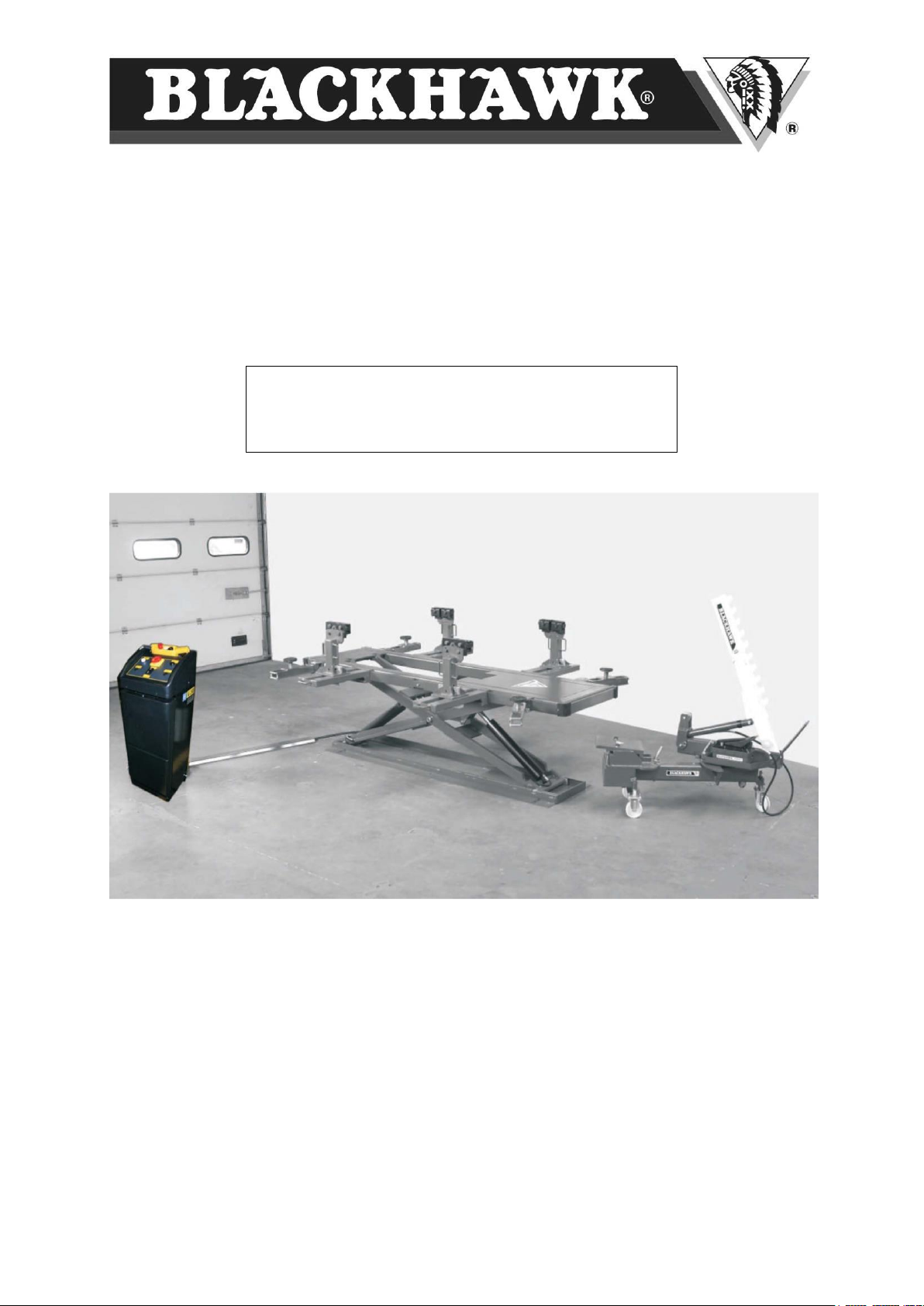
POSTLIFT
PL10C / PL20B
INSTRUCTION MANUAL
(Original manual)

________________________________________PL10C / PL20B_____________________________________
Page Nr.
I)
WARNINGS – SAFETY INSTRUCTIONS
3 - 7
II)
INTRODUCTION
8 III)
PACKING, TRANSPORT AND STORAGE
8 IV)
GENERAL DESCRIPTION
9
V)
TECHNICAL SPECIFICATIONS
10 - 11
VI)
INSTALLATION
11 - 13
VII)
PULLING SYSTEM
14 - 16
VIII)
MAINTENANCE
17 IX)
TROUBLESHOOTING
18
X)
ELECTRIC DIAGRAM
19 - 22
XI)
HYDRAULIC DIAGRAM
23 XII)
SPARE PARTS
24 - 32
XIII)
MAINTENANCE BOOKLET
33 - 36
XIV)
DECLARATION OF CONFORMITY
37
Index
2
________________________________________PL10C / PL20B_____________________________________
I) WARNINGS – SAFETY INSTRUCTIONS
The manufacturer hereby refuses to accept any responsibility for injury to persons or damage to equipment or
property if it appears that incorrect handling of the lift has occurred. This instructions manual only describes the
operating and safety aspects which are necessary to the people who are installing the equipment.
In order to understand the terminology used in this manual, the person performing the installation work should
have specific experience in industrial work, service, maintenance and repair activities, and must also be able to
explain the drawings and the descriptions contained in this manual to other people. At the same time, he must be
aware of the general and specific safety regulations which apply in the country where the lift is being installed.
SECURITY
It is important to read this section carefully since it contains important information about the risks which the
operator of the lift will be exposed to if the lift is not used properly. Please find below useful information about how
to avoid dangerous situations.
WARNING
The lift is designed to lift vehicles and hold them in a certain position in a covered working place.
Any other form of use is forbidden
In short, the lift is not suitable for the following purposes:
- Washing and spraying work
- To apply force
- To be used as a goods lift
The manufacturer hereby refuses to take into account any claim for damages arising in connection with person’s
injury or damage to vehicle or other property due to incorrect and/or unauthorized use of the lift.
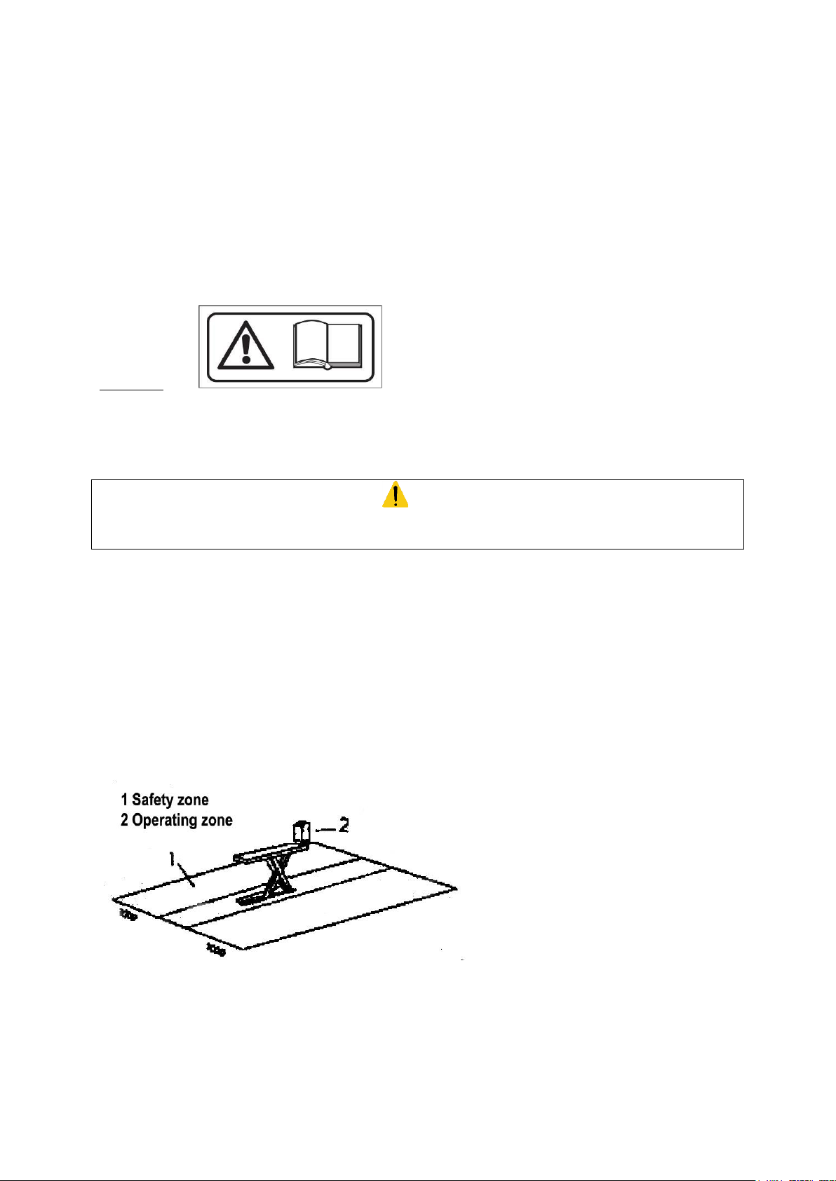
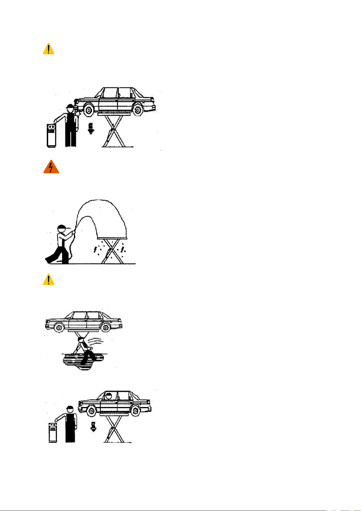
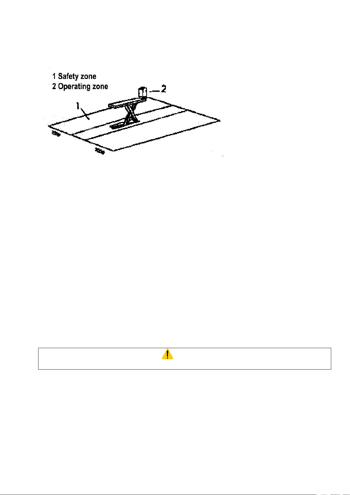
During lifting and lowering movements, the operator must be within the work area (2), as shown in figure 1. The
presence of any person in the safety zone (1) is strictly forbidden. The presence of people under the vehicle is
only permitted if the vehicle is in high lifting position.
Figure 1
Bring the lifting arms back to the centre before you lower the lift inside the pit. (In-floor version)
3
________________________________________PL10C / PL20B_____________________________________
WARNING
USE THE LIFT ONLY IF ALL THE SAFETY DEVICES ARE WORKING PROPERLY. IF THESE RULES ARE
NOT FOLLOWED, SERIOUS INJURY COULD BE CAUSED TO THE PERSON AS WELL AS IRREPARABLE
DAMAGE TO THE LIFT AND THE VEHICLE ON THE LIFT.
GENERAL PRECAUTIONS:
- The operator is bound to follow the regulations which apply in the country in which this lift is installed.
In addition, the operator must:
- Always work in the work area as designated in the manual.
- Never remove the protective guards or dismantle or shut down the mechanical, electrical or other types
of safety arrangements.
- Read the safety regulations related to the lift and read the safety information provided in this manual
The following terms have been used in this manual to describe the various types of risk:
DANGER: there is a direct possibility of danger which could lead to serious injury or death
WARNING: indicates situations and / or actions which are unsafe and could lead to injuries of various
types except death.
CAUTION: indicates situations and/or actions, which are unsafe and could lead to light injuries to
persons and/or damage to the lift, the vehicle and other properties.
RISK OF DAMAGE DUE TO ELECTRICITY: special safety arrangements have been made
on the lift in places where the risks are very high.
RISK AND PROTECTIVE MEDIA: the risk to which the operator is exposed when the vehicle is in a
raised position, together with the protective media which have been installed, in order to limit the possible
dangers.
DANGER
It is strictly forbidden to use the lift before it is fixed to the ground.
(Risk of tipping over)
Fasten the lift to the ground by the means of the bolts supplied, as indicated in the chapter INSTALLATION
WARNING
Do not move the vehicle when it is on the platform. The platforms and the rubber fittings should only be removed
at the lowest lifting position, and when there is no load
The vehicle must be placed on the lift in such a way that there is a uniform distribution of weight over the
platforms.
To ensure the safety of persons and materials, you must check that:
- The safety zone is kept under observation during the lifting process
4
________________________________________PL10C / PL20B_____________________________________
SAFETY DEVICES
The following safety devices have been installed to prevent overloading and damage.
- A hydraulic protection prevents descending of the lift in case of hose fracture.
- Thermal protection switches the power off in case of overloading.
- Overpressure valve offers protection against damage due to excessive lifting.
- A limit-switch to limit the upward movements
- A buzzer warns you about the risk of crushing when the lift is brought to its lowest position.
- Bolts for fixing the lift to the ground
RISKS TO PEOPLE
This paragraph describes the risks to which the operator or any other person near the working area where the lift
is in operation are exposed, if the lift is not used in the appropriate manner.
Never rest any fittings or other objects against the platform and never place such objects under the platform when
there is a load on it, since this can impede the lowering operations and may cause the vehicle to fall off the
platform. (Figure 2)
Figure 2
RISK OF USE / MAINTENANCE
Blackhawk uses material of the highest quality in its lifts. These must be used according to the standard specified,
and maintenance must be carried out regularly.
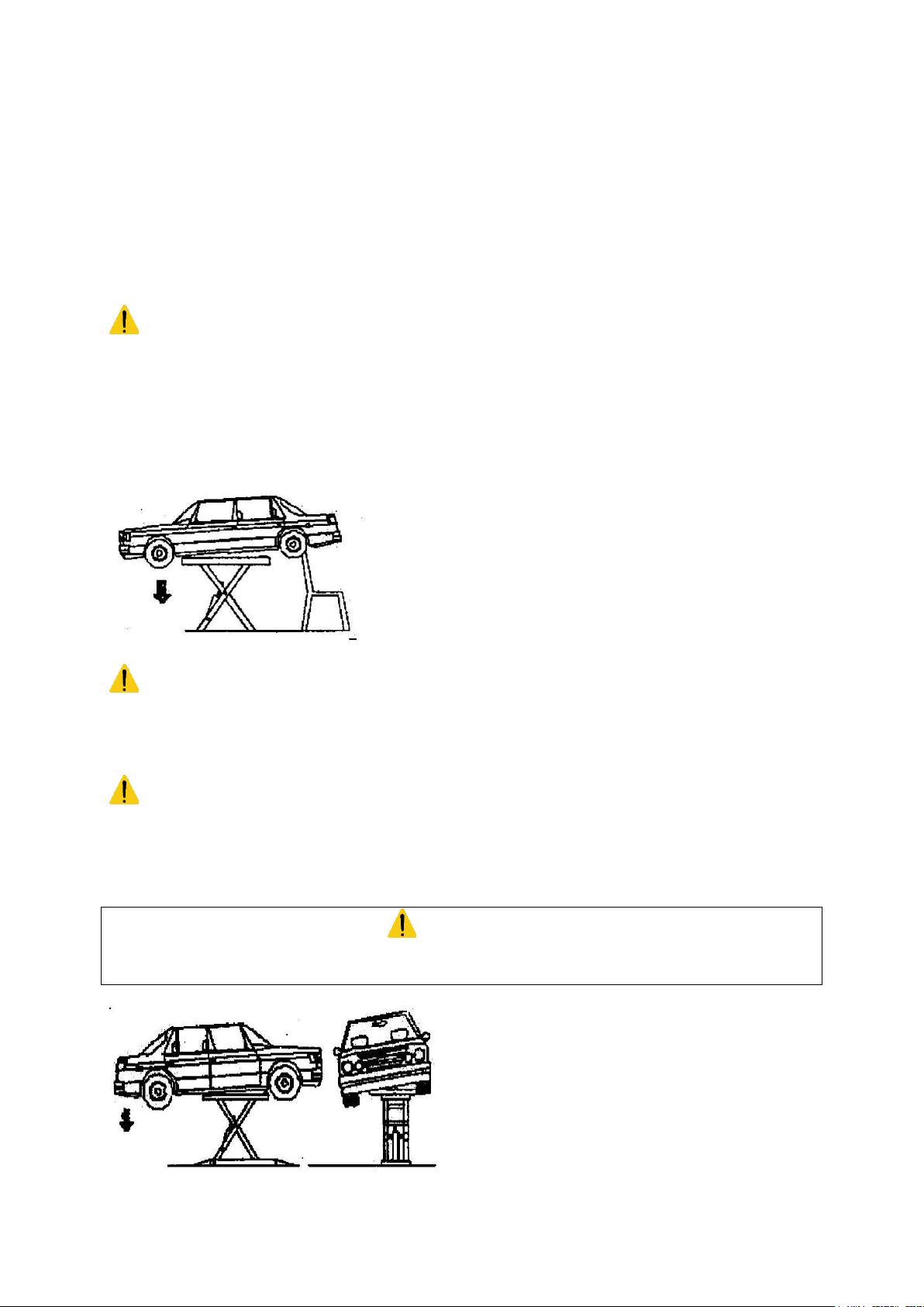
RISKS INVOLVED IN POSITIONING A VEHICLE
This type of risk may arise if the vehicle is not properly placed on the rubber supports (figure 3), or if the platforms
are not properly aligned with respect to the vehicle. One can avoid this by always lifting the vehicle using the carjack support points, and placing the vehicle as far as possible in the centre of the platform.
CAUTION
While dismantling heavy parts (for example the motor or shafts), please note that the weight distribution ratios
change.
Figure 3
5
________________________________________PL10C / PL20B_____________________________________
RISK FOR THE OPERATOR (Figure 4)
This risk arises in cases when the operator is not standing in the correct place by the pump. When the lift with the
vehicle is being lowered, the operator MUST NOT stand below the descending system. It is imperative that the
operator MUST be standing in the operating zone during the lifting and lowering operations.
Figure 4
RISK OF ELECTROCUTION
Never spray water or steam of solvents or paint in the area immediately surrounding the platform and the pump.
(Figure 5)
Figure 5
RISK OF SLIPPING
This risk can be overcome by avoiding the spillage of oil or grease in the area surrounding the lift. Apart from that,
any oil spillage which may occur should be thoroughly removed from the spot. (Figure 6)
Figure 6
Never enter the vehicle or start the motor when the vehicle is on the lift. (Figure 7)
Figure 7
6
________________________________________PL10C / PL20B_____________________________________
RISKS DUE TO STRAIGHTENING
DANGER
The straightening systems have been designed for the use of important forces. Improper installation or
preparation, unsafe anchoring of the vehicle and its accessories or the use of defect, damaged or overloaded
chains or other equipment can cause damages or personal injury, even death.
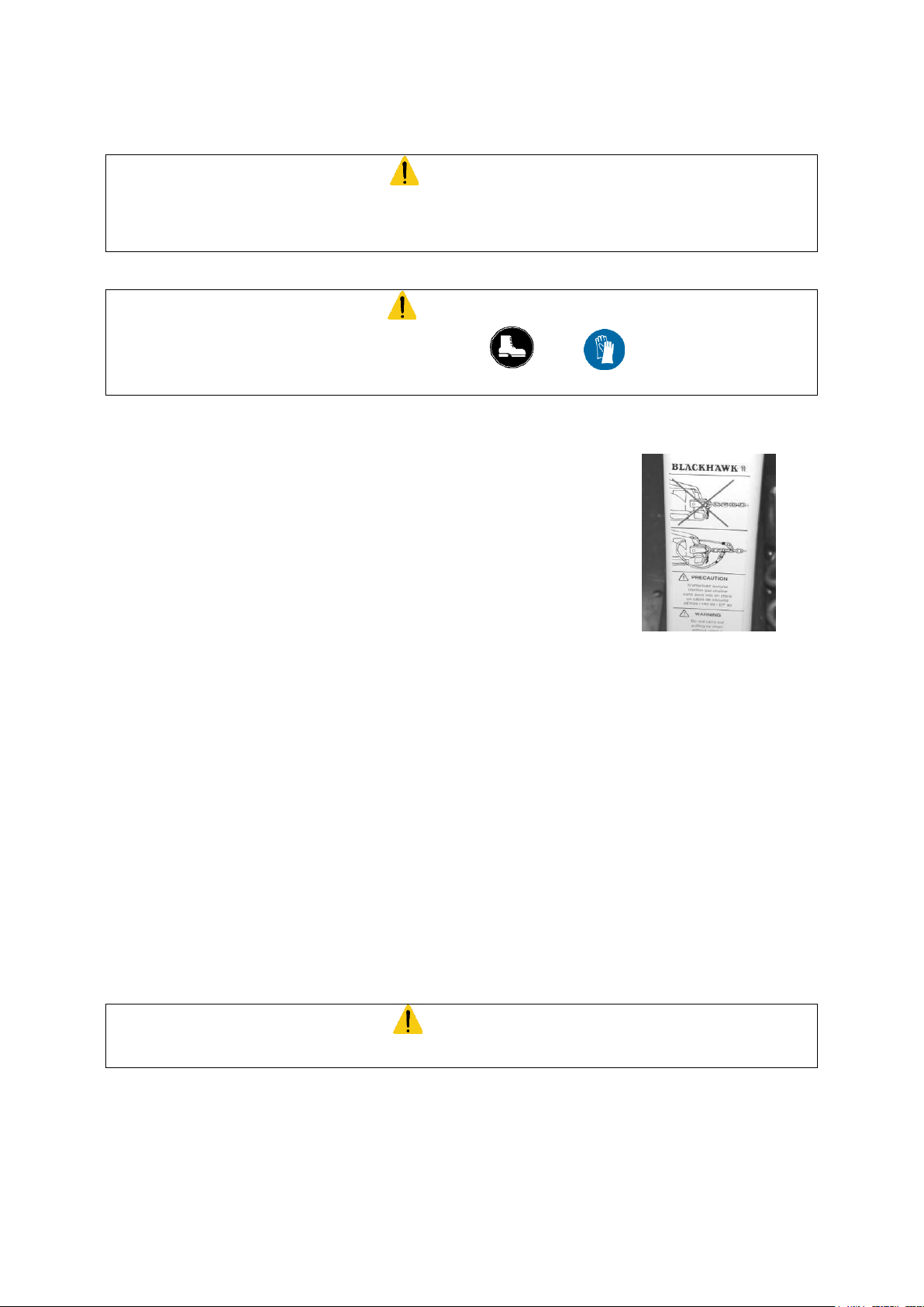
CAUTION
You must wear individual protective equipment (safety shoes , gloves ) during both the installation
and use of the equipment.
- Do not use any other chains than those supplied with this equipment.
Display in your workshop, explain and respect the safety and stocking
instructions supplied with the pulling chains.
- Always use the safety cable for pulling with the chains.
- Do not wind chains, cables or straps around the sharp parts of the vehicle, or they could be damaged.
- Do not stand in front of or behind the pulling devices while in use.
- Always make sure that the anchoring and pulling accessories and clamps are correctly set up.
- Keep the jaws of the clamps clean to avoid sliding. Replace used or damaged jaws.
- Always set up the Dozer and lock it to the frame before lifting or performing a pull. Set up the rotation-
locking axis of the arms before pulling.
- Always set up and lock the Dozer to the frame before rotating the Dozer arms to adjust the pulling angle.
Put the arms of the Dozer back in vertical position and lock your Dozer by the means of the axis before
you remove it from the frame.
- Do not exceed the maximum allowed capacity of the (PMP8111).pump: 700 bars
- Do not use the hydro-electric pump in places where there is a risk of combustible vapours.
CAUTION
Never let any incompetent or insufficiently trained person use this equipment.
DECALS:
It is your responsibility to keep all warning and safety decals clean and legible at all times. Please contact
BLACKHAWK for free replacement decals.
7
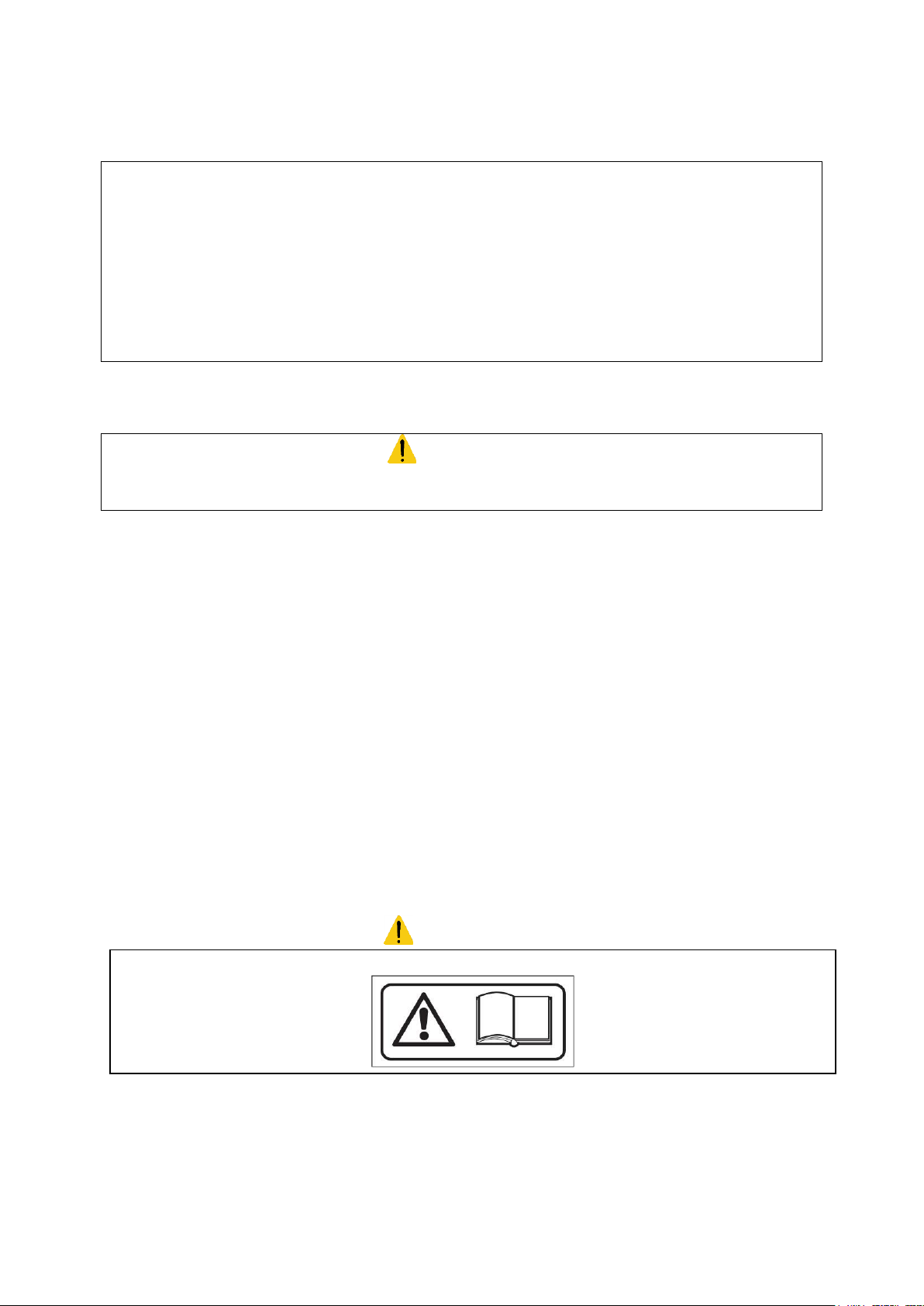
________________________________________PL10C / PL20B_____________________________________
It is strongly recommended to carefully read the safety instructions first.
II) INTRODUCTION
- This instruction manual has been prepared for professional workshop personnel, used to work with lifts, as well
as for the technicians who are in charge of the lift’s installation and maintenance (PL20).
-The straightening system BLACKHAWK POSTLIFT (PL10) (can be used with either the universal mechanical
measuring system BLACKHAWK P188, or the measuring gauges or the ultrasonic, electronic system SHARK.
This instruction manual has been prepared to explain to highly-qualified professional workshop personnel the way
this equipment functions, not to explain to amateurs the rudiments of vehicle repair. Therefore it does not give a
list of all the possible damages that can be encountered, nor the equipment needed for a particular straightening
job, nor all the possible combinations of accessories and equipment.
If you have questions relating to the POSTLIFT system, please contact BLACKHAWK, or its distributor.
III) PACKING, TRANSPORT AND STORAGE
CAUTION
Any action involving the operation, transportation or unpacking of the equipment must ONLY be performed by
trained personnel with a proper knowledge of the lift and of the contents of this operating manual
LIFTING AND MOVING THE PACKING
The wooden crates must be lifted and moved with the help of a fork lift or a crane.
The chosen equipment must be capable of lifting and moving the equipment safely, keeping in mind the
dimensions of the vehicle, the weight, the centre of gravity, as well as the fragile parts.
WEIGHT OF THE LIFT: 500 Kg
WEIGHT OF THE PUMP: 50 Kg
WEIGHT OF THE PULLING ARM WITH CLAMPS AND ACCESSORIES: 820 Kg
STORAGE
The packed lift must always be placed in a covered area at a temperature between -10°C and +40°C and must
not be exposed to direct sunlight.
OPENING THE CRATES
Make sure the equipment has not been damaged during transport, and whether all the components mentioned in
the packing list are physically present.
WARNING
8
________________________________________PL10C / PL20B_____________________________________
5
4 3 2
1
8 (*)
7 (*)
6
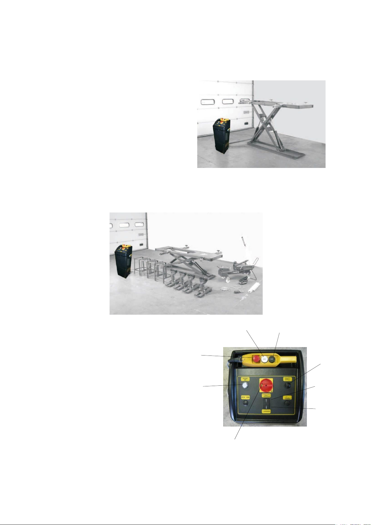
IV) GENERAL DESCRIPTION
The electric hydraulic lift PL20 can be either placed on the floor or in a pit. It has been designed and
manufactured for lifting cars and holding them in elevated position.
The main parts of the lift are:
- welded base
- moving parts
- lifting parts
- control part
- safety devices
- control cabinet (pump)
Figure 8
The PL10 set is composed of all these elements plus a pulling arm, a vertical extension, 4 anchoring clamps, 4 wheel
supports and various pulling accessories (clamp, chain, safety cable…).
It has been designed for lifting vehicles and keeping them at working height, securing them with the anchoring clamps and
straightening them.
. Figure 9
- Control cabinet (pump): (Figure 10)
1 - Descent button (remote control)
2 - Lifting button (remote control)
3 - Emergency stop (remote control)
4 - Voltage monitoring lamp
5 - Main switch
6 - Safety signal (buzzer)
7 - Lifting button (*)
8 - Descent button (*)
NB : The buttons marked (*) do not function if the remote control is connected.
Figure 10
9
________________________________________PL10C / PL20B_____________________________________
V) TECHNICAL SPECIFICATIONS
Lifting capacity: 2500 kg
Lifting time: 50 seconds
Lowering time: 1 mn 40 seconds
Total weight (PL20): 550 kg
Total weight (PL10): 1370 kg
Noise level: 70 dB(A) / 1m
Working temperature: -10°C / +40°C
Working environment: covered
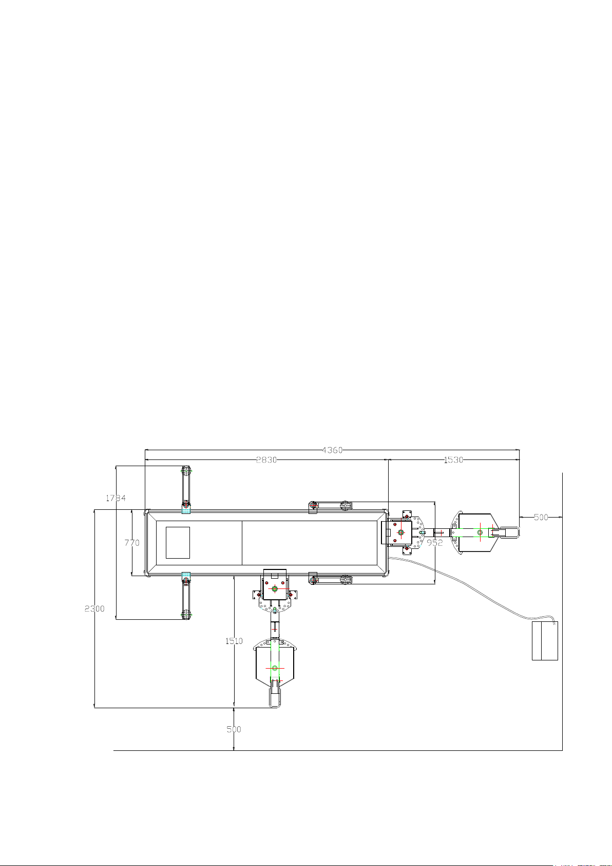
Dimensions :
Minimum height: 115 mm
Maximum height: 1700 mm
Width of frame: 770 mm
Length of frame: 2830 mm
Electromotor
Motor power: 1.1 kW
Voltage: 230V / 400V, 3 ph., +/-10%
Frequency: 50 Hz
Amperage: 230V : 5.8 A
400V : 3.4 A
Number of wires: 3 + earth
Speed: 1380 rpm
Figure 12
10
________________________________________PL10C / PL20B_____________________________________
THE WEIGHT OF THE VEHICLE
The lift can be used with nearly any vehicle provided that the maximum loading capacity (2500 kg) is not exceeded.
The safety zone (Figure 13) is to some extent determined by the dimensions of the vehicle to be lifted.
Figure 13
VI) INSTALLATION
The lift must be installed taking into account the dimensions of the vehicles to be lifted.
The minimum distance from the walls should be 1900 mm for the PL10 version.
The minimum distance from the walls should be 750 mm (on the side) and 1900 mm (at the back) for the PL20.
- Sufficient room for operations
- Sufficient room to carry out maintenance, as well as space for access- and exit-routes.
- Position in relation to other machines
- The lift must be installed near a power supply point, to enable problem-free power connection.
LIFTING
The lifts must be adequately and uniformly lighted.
FLOOR
The lift must be installed on a flat, horizontal and sufficiently sturdy floor.
The concrete floor must have a minimum thickness of 150mm and a resistance of C20/25 (Norm EN206-1)
INSTALLATION IN A PIT
The lift must be installed following the instructions and civil engineering plans supplied by Blackhawk.
WARNING
No unauthorised person should be present during installation
11
________________________________________PL10C / PL20B_____________________________________
INSTALLATION OF HOSES
1. Remove the packing from the lift.
2. Lower the lift into the place where it is to be installed using a load lifting equipment with sufficient capacity.
While doing this, keep in mind the locations of the hose connections.
Insert the hydraulic hoses and the limit switch wires through the pipe into the pump.
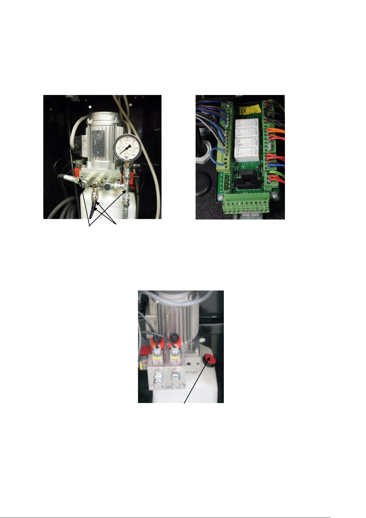
3. Connect the hydraulic hoses to the valve block of the pump. (Figure 14).
Figure 14 Figure 15
Oil return hose
Hydraulic connections
4. Connect the limit switch cables of the lift to the XT6 connector of the pump circuit board. (Figure 15).
FILLING THE HYDRAULIC SYSTEM
Fill the oil tank with around 10 litres of hydraulic oil, for example BLACKHAWK oil LX22Y or Fina Hydran TS32 or similar
oil. (Figure 16)
CONNECTING TO THE MAINS
Figure 16
Oil filler cap
12
 Loading...