

BLACKHAWK! ISO110 Quick Start Manual
1 4
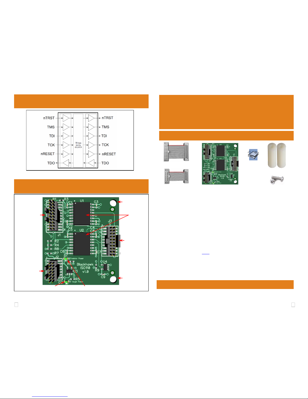
FIGURE 3 - Isolated JTAG Signal Block Diagram
FIGURE 4 - ISO110 Board Details
QUICK
START
GUIDE
5 ISO110 Board Details
Blackhawk™
ISO110
Isolation
Adapter(ISO110)
Blackhawk
123 Gaither Drive, Mt. Laurel, NJ 08054-1701
www.blackhawk-dsp.com
Blackhawk is a registered trademark of EWA Technologies, Inc.
BH-ISO110-QS-01
Items in the Box
20-pin Ribbon Cable
ISO110 Board
Stand-offs
14-pin Ribbon Cable Screws
Installation Requirements
XDS110 Debug probe
20-pin JTAG Ribbon Cable (from XDS110 Debug Probe)
Target Board with 1149.1 JTAG interface and I/O voltages from 1.8 to 5.0 volts
Pin Converter to target board JTAG connection (optional)
Important Environmental Considerations
Caution is necessary to minimize ESD (Electro-static Discharge) which can
damage electronic components. Use in a controlled environment where ESD
materials and practices are employed is highly recommended.
Limitations
EMU JTAG signals for boot modes/input triggers are not supported
The energy trace feature of the XDS110 debug probe is not supported
Bi-directional JTAG signals are not supported (i.e. cJTAG, SWD)
4 Isolated JTAG Signals
DEBUG
PROBE
SIDE
TARGET
BOARD
SIDE
J2 14-pin Ribbon
Cable Connection
To XDS110 AUX
Connector
J1 20-pin Ribbon
Cable Connection
to XDS110 DEBUG
Connector
J3 20-pin JTAG
Ribbon Cable
Connection to
Target Board
D2 Target Power LED D1 Emulator Power LED
U1/U2 Digital
Isolators
Hole for
Stand-Off
(optional)
Hole for
Stand-Off
(optional)
LED Operation
The Emulator Power LED (D1) will illuminate when the XDS110 supplies power
to the ISO110 board. This may not occur until the debug session is launched or
a target connect has been initiated by Code Composer Studio.
The Target Power LED (D2) will illuminate only when the target board is supply-
ing power (J3 - Pin 5) AND the XDS110 is supplying power (D1 is illuminated).
Quick Start
Guide,
Warranty
and
Registration
info
2 3
CCS Configuration 3
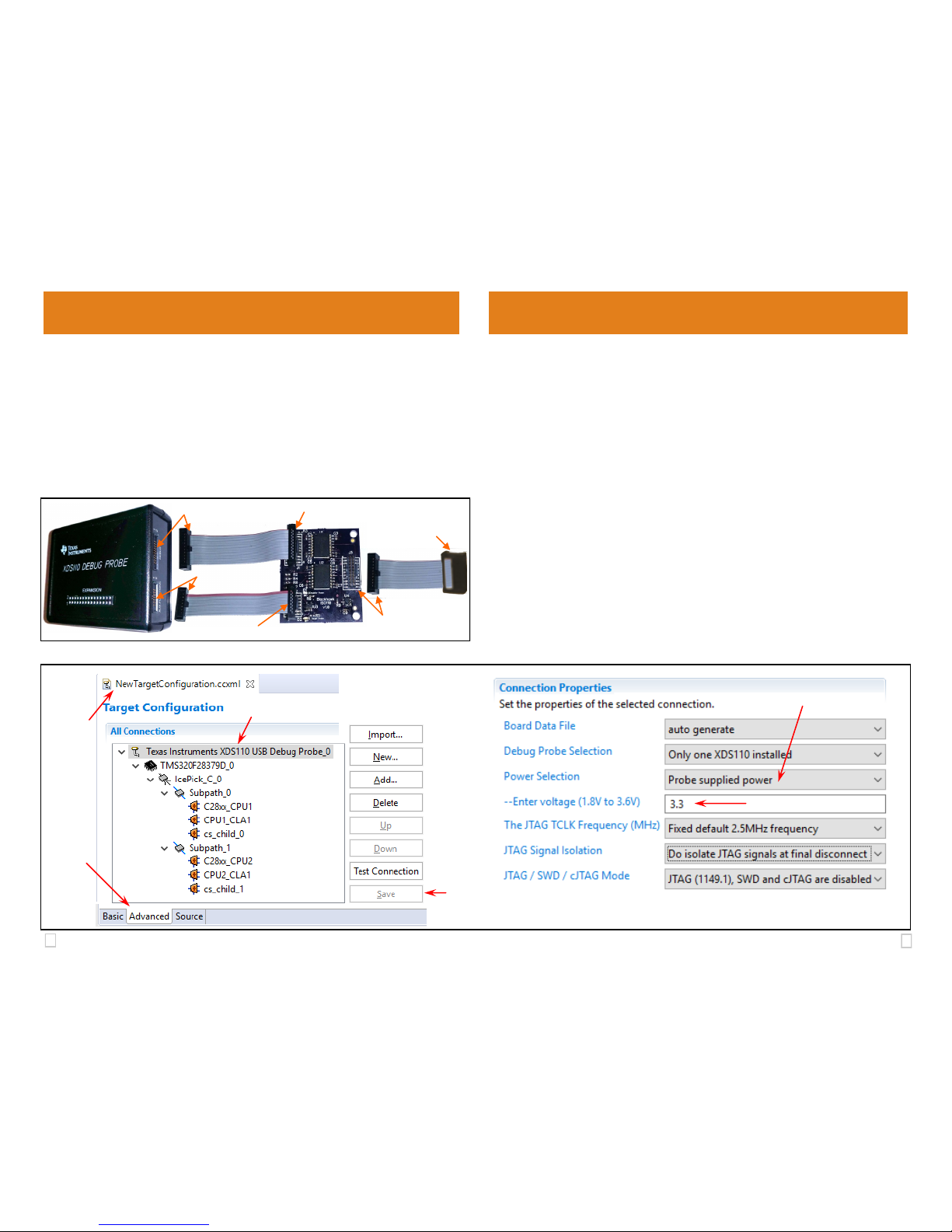
2 Cable Connections
1. If attached, detach the 14-pin and 20-pin ribbon cables from the XDS110 debug probe’s AUX and DEBUG connectors.
2. Attach the supplied two inch 20-pin and 14-pin ribbon cables (if not already
attached) to J1 and J2 of the ISO110 board respectively (see figure 1).
3. Attach the other end of the 20-pin and 14-pin ribbon cables to the corresponding XDS110 AUX and DEBUG connectors (see figure 1).
4. Attach the XDS110’s 20-pin JTAG ribbon cable to J3 of the ISO110.
5. Attach the other end of the XDS110’s 20-pin JTAG cable to your target board.
6. The stand-offs are optional and attach to the holes shown in figure 4 to prevent
the PCB from touching the bench or table underneath as needed.
FIGURE 1 - ISO110 Cable Connections
Step 2: 20-pin & J1
Step 2: 14-pin & J2
Step 3: 14-pin & AUX
Step 3: 20-pin & DEBUG
Step 4: 14-pin & J2
Step 5: 20-pin &
Target board
To use the ISO110 with Code Composer Studio, you need to configure the
XDS110 Debug Probe setting to output 3.3v on the AUX connector. The
steps below describe how to accomplish this using the CCS target configuration dialog. This assumes that you already followed the steps in section 2.
Please refer to figure 2 below when following these steps.
A. Start Code Composer Studio.
B. Edit your current XDS110 target configuration or create a new one (File >
New > Target Configuration File) for XDS110 and your target device.
The example in figure 2 uses the XDS110 and an F28379D device.
C. Select the Advanced tab in the target configuration.
D. Select the XDS110 Debug Probe in the All Connections tree view.
E. Select Probe supplied power option in the Power Selection of the
Connection Properties.
F. This will display a voltage field text box where you will enter 3.3.
G. Save the setup by pressing the Save button.
Now you are ready to launch the debug session.
FIGURE 2 - CCS Target Configuration
C
B
D
E
F
G
 Loading...