

BLACKHAWK! BH560v2 Quick Start Manual
1 4
QUICK
START
GUIDE
6 CCStudio Setup
Blackhawk™
XDS560v2
System Trace
Emulator
(BH560v2)
CCStudio v4.2 and later
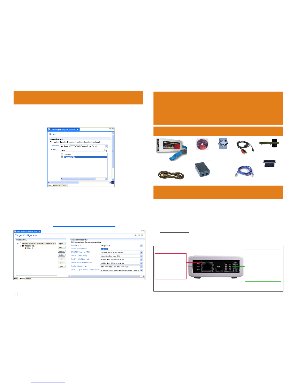
• In the CCSv4 Target Configuration General Setup window (see figure 5 below) simply
select the Blackhawk XDS560v2-LAN System Trace Emulator connection.
• Type your device or board in the device list and check the box on the left.
Blackhawk
123 Gaither Drive, Mt. Laurel, NJ 08054-1701
www.blackhawk-dsp.com
Blackhawk is a registered trademark of EWA Technologies, Inc.
BH560v2-QS-02
FIGURE 5 - CCS v4 Basic Target Setup
PoE injector
Power Supply
AC Wall Cord
Related Items
CAT5e Network
Cables (2)
1 Software Installation
DO THIS FIRST!
Install CCStudio v4.2 or later before connecting the emulator hardware to the PC
or network.
All the files needed to use the BH560v2 are installed as part of the CCS v4.2 or later installation from TI. This includes the necessary Windows device drivers for both 32 and 64 bit
operating systems.
For software updates:
use the automated CCS v4 update tool under the help menu.
For CCS v4 questions:
visit the TI Wiki Site: http://www.tiexpressdsp.com/index.php/CCSv4
• Choose the “Advanced” tab.
• Highlight the Emulator Connection Name.
• Type in “The Emulator IP Address” Box your emulator Static or DHCP IP address.
(see figure 6 below)
• Save this setting and launch the TI Debugger.
For more information on CCS v4, please visit the TI Wiki site:
http://www.tiexpressdsp.com/index.php/CCSv4
FIGURE 6 - CCS v4 Advanced Target Configuration
FIGURE 1 - BH560v2 Host End Panel & Indicators
MIPI 60
Pin Converters (4)
TI 14
ARM 20
cTI 20
TI 60 - trace
CD ROM
BH560v2 Emulator &
Target Cable
Quick Start
Guide,
Warranty
and
Registration
cards
USB Cable
Target Cable
Buffer Board
RJ45 Connector
with LED Indicators
Connector is POE Compliant for use with POE
power supply injector.
(IEEE802.3af compliant)
LED Status Area
A1: Reserved
A2: HOST Activity
A3: Target Activity (STM)
S1: CCS Connected
S2: FPGA Programmed
S3: DTC Ready
U: USB Enum/Activity
5V: Unit is powered
2 3
Configuration and Test 5
• Install CCS v4.2 FIRST. Do not attach hardware until step 1 is completed.
• Place the BH560v2 module in desired location so that the JTAG cable can
reach your target board’s JTAG connector.
• Attach the JTAG cable assembly to the target board. Make sure the target is
not powered when connecting!
• Attach the supplied BLUE LAN network cable to the LAN connector on the
PoE injector as shown in figure 4.
2 Emulator Cable Assembly
3 LAN PC Connection
• Attach the buffer board to the JTAG cable by pressing the connectors together
with the correct orientation making sure the cable side of the buffer board is
facing the cable (figure 2B).
• Attach the pin converter that matches the JTAG connection of your target
board to the buffer board (figure 2B).
• Connect the other end (with thumbscrews) to the emulator pod. You do this by
pressing the cable to the BH560v2 pod’s cable connector and then gently tightening the thumbscrews (figure 2A).
For additional details please refer to the BH506v2 installation guide.
• Launch the BH560v2Config Utility either from the desktop shortcut or from your
programs start menu.
The utility will search for the BH560v2 on the network. By default the BH560v2 is set to
obtain DHCP IP address from your router, the address will be displayed under the device
section in the utility. If, for some reason, the unit is not located you can enter the device
list information manually, or use the USB connection to configure the unit.
For more details, please refer to the Bh560v2Config User Guide. It is accessible
from the utilities help menu.
• The utility is graphical and intuitive, allowing you to perform tests or changes set-
tings by highlighting a device shown in the device list (see figure 3).
• For example, you can set a Static IP address , by following these steps
− Click on the “Edit Device Parameters” button.
− Highlight the “ipConfig” parameter in the list.
− Modify the value from “dhcp” to your desired static ip value (i.e. 10.0.9.1).
− Click on the “Set” button.
− Click on the “Reboot” button to restart the emulator
Powering the BH560v2 unit, can take 20 seconds for the device to BOOT.
PoE Switch: If you have a Power over Ethernet (PoE) switch, you can connect
the unit directly to it for data and power using the supplied
BLACK
network cable.
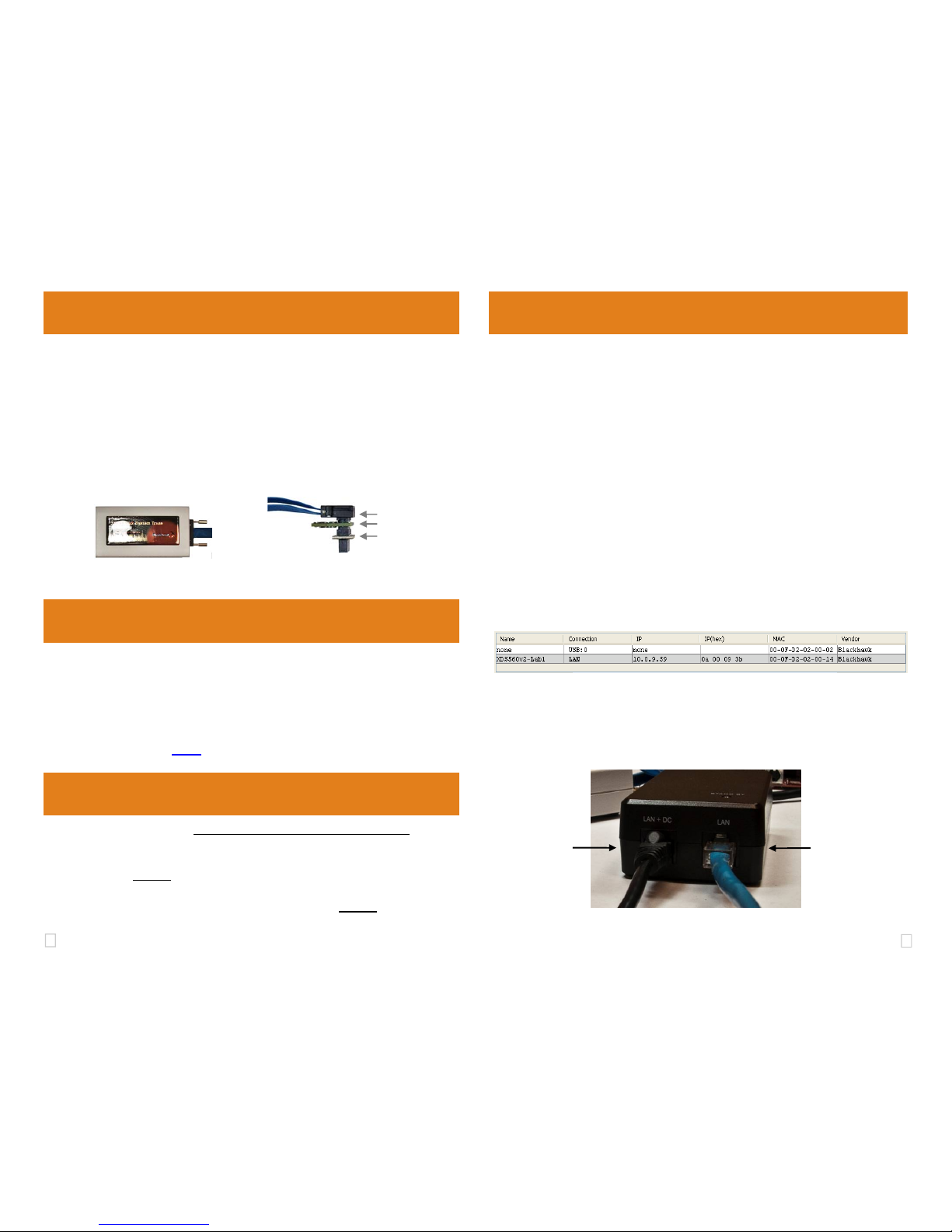
PoE Injector: If powering using a PoE injector (power supply), connect the unit’s
RJ45 to the PoE supply using the supplied BLACK
network cable
to the LAN+DC PoE injector port as shown in figure 4.
FIGURE 3 - BH560v2 Config Utility Device Section
PoE Injector
LAN
Connection
PoE Injector
LAN+DC
Connection
FIGURE 4 - PoE Injector’s RJ45 Connections
LAN
LAN + DC
4 Power
FIGURE 2A - BH560v2 and Cable
assembly
JTAG Cable
Buffer Board
Pin Converter
FIGURE 2B - Buffer board and Pin
Converter assembly
 Loading...