

Page 1
BUGIC&DEeKER
PROFESSIONAL
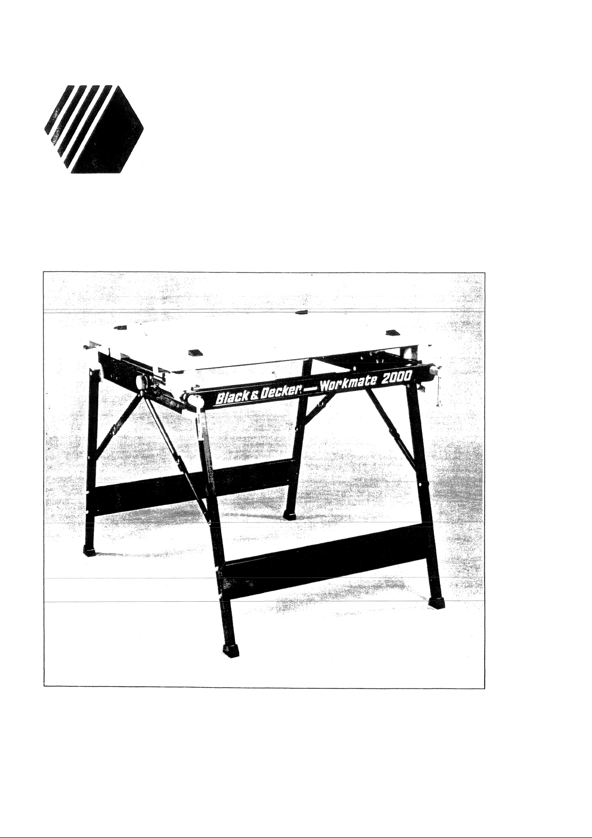
WM2000 FOLDfiWAY WORKBENCH
OPERATING INSTRUCTIONS
743190
Page 2
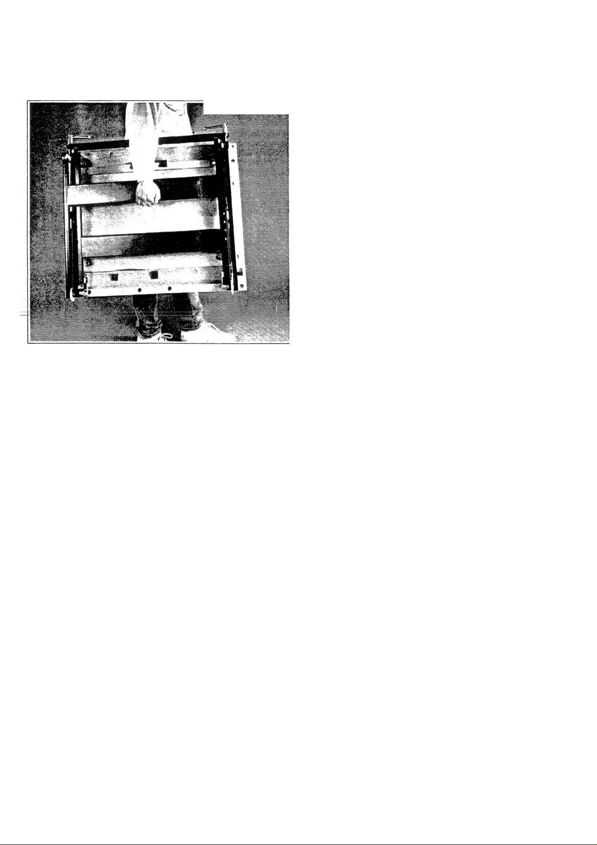
FOLDfiWAY PROCEDURE
Fig. 10
V-.*- ' ■
The WM2000 folds flat for storage,
carrying or taking to the workplace.
To fold away it is important that the
following procedure is followed.
Ensure that the centreboard is securely
clamped between the two vice jaws fig. 10
or removed altogether.
Place WM2000 flat on its work top fig. 2
and release the metal struts on the front
pair of legs and fold away.
Repeat liiis exercise for the rear legs
ensuring that the retaining latches are
engaged to hold the rear legs securely.
SAFETY INSTRUCTIONS
Do not use crossmembers as a stepladder or stand on top of the WM2000.
Never drop heavy loads onto your WM2000 always ensure that they are gently placed into
position.
Although your WM2000 can be used to provide a secure and safe mount for power tools and
attachments (use vice pegs to secure units), it is important to always disconnect the power tool
from the mains supply when setting up or making adjustments.
Check all moving parts, pivots etc for wear, damage or looseness.
Please note:
“Do not carry your WM2000 by the vice jaws. We recommend the use of the front crossmember
as a suitable carrying point. Ensure the centre board is either removed or secure before
transporting”.
Always ensure the WM2000 is used on a flat level surface.
Always locate safety locks by pressing firmly on each vice jaw before use.
Page 3
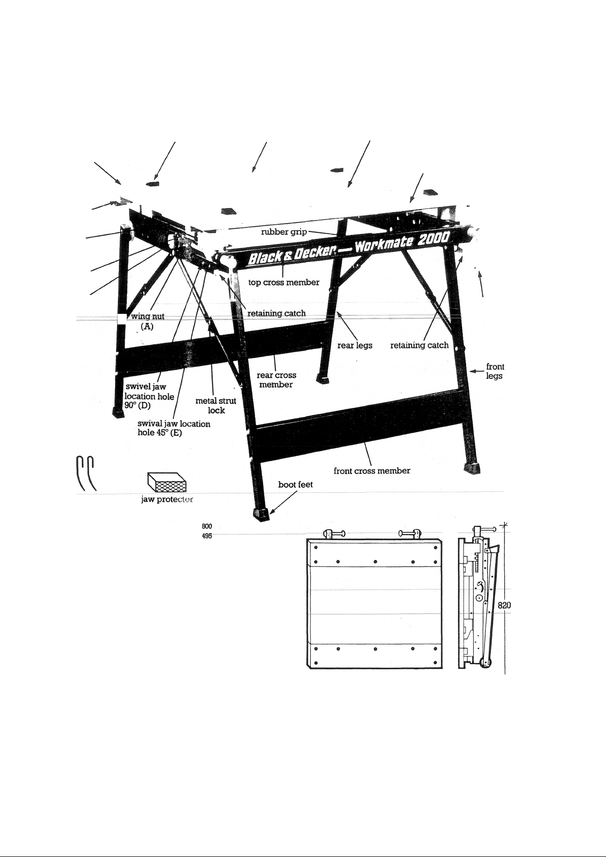
WM 2000 FOLDHWAY WORKBENCH
vice boles
snap l^k
mechanisiii
parallel
rails
hexagonal
nut (C)
cam lock
mechanism (B)
vice pe^
removable rear vice jaw
centre board
swivelling vice jaw
tommy bar
handles
metal drawing
board brackets
Working height
Max. vice jaw opening (mm)
(Centre board removed WM2000)
Work surface dimensions (mm) (L x W x II)
Vice jaw dimensions (nun) (L x W x H)
Centre board dimensions (mm) (L x W x II)
Max. vice jaw opening (mm)
(Centre board in workbench position)
Max. vice jaw opening 45° (mm)
Max. vice jaw opening ^° (mm)
(Centre board between lower cross members)
Folded dimensions (mm) (L x W x H)
Weight (Kg)
Standard equipment
ACCESSORIES Vice pegs (set of 4)
Fig.l
900 X 730 x 20
900 X 115 X 20
900 X 490 X 20
85
135
625
mxmK$m
■m
4 X vice pegs
2 X drawing board brackets
2 X jaw protectors
A»26
4- ^230-^7=
Page 4

ASSEMBLY INSTRUCTIONS
I vviiji me legs iii the
7cr:icm pcGiticr; lock
ihe meia.1 strats as sho'v/n
Fig. 2
Remove the WM2000 from packaging
ensuring that the centreboard is clamped
securely between the vice jaws.
Place the WM2000 on floor as shown in
fig. 2 and release the two retaining
catches and open the first pair of legs,
with the legs in vertical position lock &e
metal struts as shown.
Release the remaining set of legs and
foUow above procedure.
Note: Before placing the WM2000 in the
upright position ensuring all four metal
struts are locked securely.
STANDARD EQUIPMENT
Each WM2000 is supplied with:
(A) Four vice pegs - ideal for clamping
irregular shaped work pieces safely fig. 3.
(B) Two jaw protectors - ideal for
gripping pipes etc, securely either
vertically or horizontally.
(C) Two metal drawing board brackets
as shown in fig. 9.
Page 5

VICE JAWS AND CEOTRE BOARD OPERATION
By loosening the two tommy bar handles
the centreboard can be removed
converting the WM2000 into a large
capacity vice. Each tcxnmy bar works
independently so that the front vice jaw
can be adjusted into a tapered position
when required (fig. 4). The rear vice jaw is
adjusted by a snap lock mechanism
(pressure upwards releases the jaw, and
downwards pressure locks the jaw) and
can be repositioned into a series of
parallel holes (fig. 4).
The centre board can be used between
the two bottom crossframe members
when greater capacity is required fig. 4 &
fig. 7.
rig. 4
VICE JAW AND WOPJtBENCH COMBINED
Slide the centre board base supports (B)
into the rear holes of the appropriate
parallel frame.
Mote; Wiiei; correctly positioned a slight
gap remains between the rear vice jaw
and the centre board (A) (fig. 5).
Page 6

LARGE CAPACITY CLAMPING PRESS AND
90° VICE ADJUSTMENT
The swivel vice jaw can be locked in six
different 90° positions 3 front facing and 3
rear facing.
To position the swivelling vice jaw at 90°
remove the wing nuts (A) and hexagonal
nuts (C) and rotate cam lock (B) clockwise
through 45°.
Remove swivel vice jaw and reposition in
one of the above 6 positions. Secure the
swivel vice jaw following the above
procedure in reverse order.
Note: remember to use the swivel jaw
clamping press location holes (D) fig. 1.
Fig. 7
Fig. 7 shows the centre board between the
two bottom cross frames as described in
fig. 4. Allowing for greater clamping
capacity.
NOTE: The adjustable vice jaw should
be removed or placed at the end of the
parallel rails.
Page 7

' : • • .' >; - ■ *1».
■S'r .■■vi--
■&■’-; ■ ■ •■ --■
Fig. 8
The swivel jaw can be locked in six
different 45° positions 3 front facing and 3
rear facing.
Follow the procedure shown in 90°
clamping fig. 6 ensuring that the metal
pins of the cam locks are released into the
holes provided for 45° angles. (E) fig. 1.
Fig. 9
The WM2000 can be converted into a
drawing board with the aid of the two
metal brackets provided. Follow the set
up procedure in fig. 6.90° vice adjustment.
Set the swivelling vice jaw as shown in fig.
9. The removable vice jaw should be
either removed as shown in fig. 9. or
positioned at the front end of the parallel
rails.
Lock the metal brackets into the plastic
base supports (rectangtdar supports) of
the centre board and clip over the front
top cross member. As shown, fig. 9.
Page 8

TOOL SERVICING OR REPAIR
For maximum life and safe, efficient operation, we advise that your tool be returned to your nearest
Black & Decker Service Centre for re^ar cleaning, inspection and service, particularly when being
used in extremely arduous conditions. If your tool shows obvious signs of malfunction, damage or
fails to operate, return it to yoiu nearest Service Centre whose address is given in your local Yellow
Pages Directory.
Black & Decker also have Professional Repairing Distributors and Service Agents located in major
towns and cities offering the same high standard of service.
Contact a Black & Decker Service Centre for further details.
THE BLACK AND DECKER GUARANTEE
If your Black & Decker Professional product becomes defective due to faulty materials or
workmanship within 6 months from the date of purchase, we guarantee to replace all defective parts
free of charge or, at our discretion, relace the unit free of charge, provided that:
1. The product has not been misused.
2. Repairs have not been attempted by persons other than our own service staff or the staff of
authorised repairers.
3. Proof of purchase date is produced.
The guarantee is offered as an extra benefit and is additional to consumers statutory rights.
 Loading...