

Page 1

12
FULLY AUTOMATIC ELECTRONIC
SMART BATTERY CHARGER
40/20/10/4 AMP / CHARGE RATES WITH 110
AMP ENGINE START
SERVICE INFORMATION
All Black & Decker Service Centers are staffed with trained personnel to provide customers
with efficient and reliable power tool service. Whether you need technical advice, repair, or
genuine factory replacement parts, contact the Black & Decker location nearest you. To find
your local service location, refer to the yellow page directory under "Tools—Electric" or call:
1-800-544-6986 or visit www.blackanddecker.com
FULL FIVE-YEAR HOME USE WARRANTY
Black & Decker (U.S.) Inc. warrants this product for five years against any defects in
material or workmanship. The defective product will be replaced or repaired at no charge in
either of two ways.
The first, which will result in exchanges only, is to return the product to the retailer from
whom it was purchased (provided that the store is a participating retailer). Returns should
be made within the time period of the retailer’s policy for exchanges (usually 30 to 90 days
after the sale). Proof of purchase may be required. Please check with the retailer for their
specific return policy regarding returns that are beyond the time set for exchanges.
The second option is to take or send the product (prepaid) to a Black & Decker owned or
authorized Service Center for repair or replacement at our option. Proof of purchase may
be required.Black & Decker owned and authorized Service Centers are listed under
"Tools-Electric" in the yellow pages of the phone directory.
This warranty does not apply to accessories. This warranty gives you specific legal rights
and you may have other rights which vary from state to state or province to province.
Should you have any questions, contact the manager of your nearest Black & Decker
Service Center. This product is not intended for commercial use.
FREE WARNING LABEL REPLACEMENT: If your warning labels become illegible or are
missing, call 1-800-544-6986 for a free replacement.
See ‘Tools-
Electric’
– Yellow Pages –
for Service &
Sales
Imported by
Black & Decker (U.S.)
Inc.,
701 E. Joppa Rd.
Towson, MD 21286 U.S.A.
Part No. 90104835 Copyright © 2008 Black & Decker MADE IN CHINA
Sept. ‘08
Thank you for choosing Black & Decker!
Go to www.BlackandDecker.com/NewOwner
to register your new product.
PPLLEEAASSEE RREEAADD BBEEFFOORREE RREETTUURRNNIINNGG TTHHIISS
PPRROODDUUCCTT FFOORR AANNYY RREEAASSOONN::
If you have a question or experience a problem with your Black & Decker purchase, go to
HTTP://WWW.BLACKANDDECKER.COM/INSTANTANSWERS
If you can’t find the answer or do not have access to the internet,
call 1-800-544-6986 from 8 a.m. to 5 p.m. EST Mon. -- Fri. to speak with an agent.
Please have the catalog number available when you call.
for instant answers 24 hours a day.
VEA EL ESPAÑOL EN LA CONTRAPORTADA.
INSTRUCTIVO DE OPERACIÓN, CENTROS DE SERVICIO Y PÓLIZADE GARANTÍA.
ADVERTENCIA: LÉASE ESTE INSTRUCTIVO ANTES DE USAR ELPRODUCTO.
SAVE THIS INSTRUCTION MANUAL FOR FUTURE REFERENCE.
INSTRUCTION MANUAL
Catalog No.
VEC1093DBD
VEC1093DBD ENGLISH 10/2/08 9:45 AM Page 12
Page 2
iiiii
7. Remove personal metal items such as rings, bracelets, necklaces and watches when
working with a lead-acid battery. A lead-acid battery can produce a short-circuit
current high enough to cause a severe burn.
8. Use charger for charging a LEAD-ACID battery only. It is not intended to supply
power to a low-voltage electrical system other than in a starter-motor application. Do
not use the battery charger for charging dry-cell batteries that are commonly used
with home appliances. These batteries may burst and cause injury to persons and
damage property.
9. NEVER ATTEMPT TO CHARGE A FROZEN BATTERY.
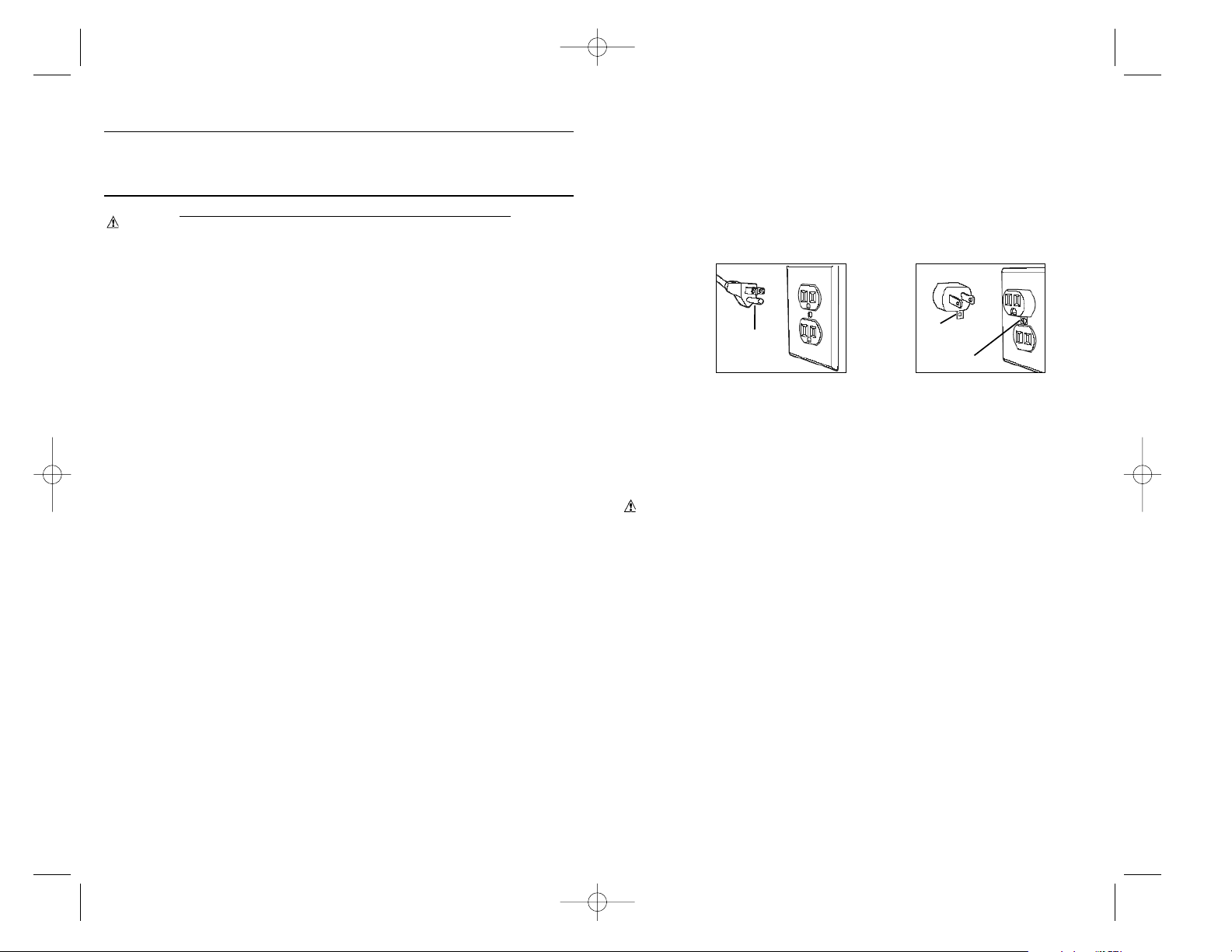
Power Cord Safety
Charger should be grounded to reduce risk of electric shock. Charger is equipped with an
AC cord having equipment-grounding conductor and a grounding plug. The plug must be
plugged into a properly installed and grounded 110/120 volt AC outlet in accordance with all
local codes and ordinances (see Figure 1A).
If a properly grounded outlet is not available, a temporary adapter (like the adapter shown
in Figure1B) may be used to connect this plug to a two-pole receptacle. The temporary
adapter should be used ONLY until a properly grounded outlet can be installed by a
qualified electrician.
DANGER — Before using an adapter as illustrated, make certain that the center
screw of outlet plate is grounded.
The green-colored rigid ear or tab extending from adapter must be connected to a
properly grounded outlet. MAKE CERTAIN IT IS GROUNDED. If necessary, replace
original outlet cover plate screw with a longer screw that will secure adapter ground tab to
outlet cover plate and connect to grounded outlet.
WARNING
NEVER alter AC cord or plug. If it will not fit, have a proper outlet installed by a
qualified electrician. Improper connection may result in an electric shock.
Note: Use of an adapter is not allowed in Canada. If a grounding type receptacle
is not available, do not use this appliance until the proper outlet has been
installed by a qualified electrician.
Preparing to Charge
1. Determine voltage of battery to be charged by referring to the owner's manual.
2. If it is necessary to remove battery from vehicle to charge, or to clean terminals,
always remove grounded terminal from battery first. Make sure all accessories in the
vehicle are off, so as not to cause an arc.
3. Clean battery terminals. Do not allow corrosion to come in contact with eyes.
4. Add distilled water in each cell until battery acid reaches level specified by battery
manufacturer. This helps purge excessive gas from cells. Do not overfill. For a battery
without cell caps (maintenance free), carefully follow manufacturer's charging
instructions.
5. Study all battery manufacturer’s specific precautions, such as removing or not
removing cell caps while charging, and recommended rates of charge.
6. Area around battery should be well ventilated while battery is being charged. Gas can
be forcefully blown away by using a piece of cardboard or other nonmetallic material
as a fan.
7. Make sure the initial charging rate does not exceed battery manufacturer’s requirement.
Charger Location
1. Locate charger as far away from battery as cables permit.
2. NEVER place charger directly above battery being charged; gases from battery will
corrode and damage charger.
3. NEVER allow battery acid to drip on charger when reading gravity or filling battery.
4. NEVER operate charger in a closed-in area or restrict ventilation in any way.
5. Marine batteries must be removed and charged on shore.
6. Do not set a battery on top of charger.
GROUNDING
PIN (A)
GROUNDING
MEANS
METAL SCREW
ADAPTER (B)
Figure
1A
Figure
1B
IMPORTANT SAFETY INSTRUCTIONS
WARNINGS
1. RISK OF EXPLOSIVE GAS MIXTURES — WORKING IN VICINITY OF A LEADACID BATTERY IS DANGEROUS. BATTERIES GENERATE EXPLOSIVE GASES
DURING NORMAL BATTERY OPERATION. FOR THIS REASON, IT IS OF UTMOST
IMPORTANCE THAT EACH TIME BEFORE USING YOUR CHARGER, YOU READ
THIS MANUAL AND FOLLOW THE INSTRUCTIONS EXACTLY.
2. To reduce risk of battery explosion, follow these instructions and those published
by the battery manufacturer and manufacturer of any equipment you intend to use
in vicinity of battery. Review cautionary markings on these products and on
engine.
3. This equipment employs parts (switches, relays, etc.) that produce arcs or sparks.
Therefore, if used in a garage or enclosed area, the unit MUST be placed not less
than 18 inches above the floor.
Battery Safety
1. Use of an attachment not recommended or sold by the battery charger manufacturer
may result in a risk of fire, electric shock, or injury to persons.
2. To reduce risk of damage to electric plug and cord, pull by plug rather than cord when
disconnecting charger.
3. An extension cord should not be used unless absolutely necessary. Use of an
improper extension cord could result in a risk of fire and electric shock, and will void
warranty.
If an extension cord must be used, make sure:
a. that pins on plug of extension cord are the same number, size, and shape as those
of plug on charger;
b. that extension cord is properly wired and in good electrical condition; and
c. that wire size is AWG#10 (10 gauge) for 100 feet and AWG#8 for distances over
100 feet.
4. Do not operate charger with damaged cord or plug — take to a qualified technician for
replacement of the plug or cord immediately.
5. Do not operate charger if it has received a sharp blow, been dropped, or otherwise
damaged in any way; take it to a qualified service technician.
6. Do not disassemble charger; take it to a qualified service technician when service or
repair is required. Incorrect re-assembly may result in a risk of electric shock or fire,
and will void warranty.
7. To reduce risk of electric shock, unplug charger from outlet before attempting any
maintenance or cleaning. Turning off controls without unplugging will not reduce this
risk.
8. Do not expose charger to rain, snow or use when wet.
Personal Safety
1. Another person should be within range of your voice or close enough to come to your
aid when you work near a lead-acid battery.
2. Fresh water and soap should be nearby in case battery acid contacts skin, clothing, or
eyes.
3. Wear complete eye protection and clothing protection. Avoid touching eyes while
working with a battery. Acid, acid particles or corrosion may get into eyes. Immediately
flood eye with cold water (Eye Wash Station) for at least 15 minutes and seek medical
attention immediately.
4. If battery acid contacts skin or clothing, wash immediately with soap and water. If
redness, pain or irritation occurs, seek immediate medical attention.
5. NEVER smoke or allow a spark or flame in vicinity of battery or engine.
6. Be extra cautious to reduce the risk of dropping a metal tool onto battery. This might
cause sparks or short-circuit the battery or other electrical part, which can cause an
explosion.
IMPORTANT SAFETY INFORMATION, SAVE THESE
INSTRUCTIONS
TO REDUCE THE RISK OF INJURY, USER MUST READ AND UNDERSTAND
THIS INSTRUCTIONAL MANUAL. THIS MANUAL CONTAINS IMPORTANT
INFORMATION REGARDING THE OPERATION AND WARRANTY OF THIS
PRODUCT. PLEASE RETAIN FOR FUTURE REFERENCE.
VEC1093DBD ENGLISH 10/2/08 9:45 AM Page ii
Page 3

1
TABLE OF CONTENTS
Introduction . . . . . . . . . . . . . . . . . . . . . . . . . . . . . . . . . . . . . . . . . . . . . . . . . . . . . . . 1
Features . . . . . . . . . . . . . . . . . . . . . . . . . . . . . . . . . . . . . . . . . . . . . . . . . . . . . . . . . . 2
Controls and Indicators . . . . . . . . . . . . . . . . . . . . . . . . . . . . . . . . . . . . . . . . . . . . 3
Operating Instructions . . . . . . . . . . . . . . . . . . . . . . . . . . . . . . . . . . . . . . . . . . . . . . . 5
Charge Rate Selection . . . . . . . . . . . . . . . . . . . . . . . . . . . . . . . . . . . . . . . . . . . . . 5
Charging the Battery . . . . . . . . . . . . . . . . . . . . . . . . . . . . . . . . . . . . . . . . . . . . . . 5
Automatic Float Charging . . . . . . . . . . . . . . . . . . . . . . . . . . . . . . . . . . . . . . . . . . 6
Equalizing . . . . . . . . . . . . . . . . . . . . . . . . . . . . . . . . . . . . . . . . . . . . . . . . . . . . . . . 6
Engine Start . . . . . . . . . . . . . . . . . . . . . . . . . . . . . . . . . . . . . . . . . . . . . . . . . . . . . 7
Recondition Mode . . . . . . . . . . . . . . . . . . . . . . . . . . . . . . . . . . . . . . . . . . . . . . . . 7
Alternator Check . . . . . . . . . . . . . . . . . . . . . . . . . . . . . . . . . . . . . . . . . . . . . . . . . 8
Approximate Charging Times . . . . . . . . . . . . . . . . . . . . . . . . . . . . . . . . . . . . . . . . . . 9
Care and Maintenance . . . . . . . . . . . . . . . . . . . . . . . . . . . . . . . . . . . . . . . . . . . . . . . 9
Troubleshooting . . . . . . . . . . . . . . . . . . . . . . . . . . . . . . . . . . . . . . . . . . . . . . . . . . . . 10
INTRODUCTION
Thank you for selecting the 40/20/10/4 Amp Smart Battery Charger. With
proper care and use, it will give you years of dependable service. This battery
charger has a high charge rate of up to 40 amps, a low charge rate of 4 amps
and 110 amps of engine starting power. It is designed for charging only
12 volt lead-acid batteries — conventional automotive, maintenance-free, marine
deep cycle and gel — used in cars, trucks, farm equipment, boats, RVs and
SUVs, lawn mowers/garden tractors, motorcycles, personal watercraft,
snowmobiles, ATVs and various applications.
Smart Battery Chargers feature 3-stage high-efficiency charging technology builtin microprocessor control that ensures fast, safe and complete charging of
serviceable batteries.
Charge Curve
Stage One — Rapid Start Charge at 40 amps delivers maximum charging
amperage to “wake up” any serviceable 12 volt battery and allows for quick
engine starting in just 1 minute (based on a midsize vehicle battery at 50% charge
level). When battery reaches a maximum safe predetermined voltage, the charger
will automatically signal a "beep" and move into Stage 2 of the charging process.
BEEP
BEEP
OFF BEEP
STAGE THREE
CHARGING
COMPLETE
STAGE ONE
STAGE TWO
iv
DC Connection Precautions
1. Connect and disconnect DC output clamps only after removing AC cord from electric outlet.
2. Never allow clamps to touch each other.
3. Attach clamps to battery chassis as indicated in “Battery Installed in Vehicle” steps 5 and
6, and in “Battery Outside of Vehicle” steps 2, 4 and 5.
Follow these steps when the battery is installed in a vehicle. A spark near the battery
may cause an explosion. To reduce risk of a spark near the battery:
1. Position AC and DC cords to reduce risk of damage by hood, door, or moving engine part.
2. Stay clear of fan blades, belts, pulleys, and other parts that can cause injury to persons.
3. Check polarity of battery posts. POSITIVE (POS, P, +) battery post usually has larger
diameter than NEGATIVE (NEG, N, –) post.
4. Determine which post of battery is grounded (connected) to the chassis. If NEGATIVE
post is grounded to chassis (as in most vehicles), see 5. If POSITIVE post is grounded
to the chassis, see 6.
5. For negative-grounded vehicle, connect POSITIVE (RED) clamp from battery charger to
POSITIVE (POS, P, +) ungrounded post of battery. Connect NEGATIVE (BLACK) clamp
to vehicle chassis or engine block away from battery. Do not connect clip to carburetor,
fuel lines, or sheet-metal body parts. Connect to heavy gauge metal part of the frame or
engine block.
6. For positive-grounded vehicle, connect NEGATIVE (BLACK) clamp from battery charger
to NEGATIVE (NEG, N, –) ungrounded post of battery. Connect POSITIVE (RED) clamp
to vehicle chassis or engine block away from battery. Do not connect clip to carburetor,
fuel lines or sheet-metal body parts. Connect to a heavy gauge metal part of the frame
or engine block.
7. When disconnecting charger, disconnect AC cord, remove clamp from vehicle chassis,
and then remove clamp from battery terminal.
8. Do not charge the battery while the engine is operating.
9. See operating instructions for length of charge information.
Follow these steps when the battery has been removed from a vehicle. A spark near
the battery may cause an explosion. To reduce risk of a spark near the battery:
1. Check polarity of battery posts. The POSITIVE post (marked POS,P, +) usually has a
larger diameter than the NEGATIVE battery post (marked NEG, N, –).
2. Attach a 24-inch (minimum length) 6 AWG insulated battery cable to the NEGATIVE
battery post (marked NEG, N, –).
3. Connect the POSITIVE (RED) battery clamp to the POSITIVE battery post (marked POS,
P, + or red).
4. Stand as far back from the battery as possible, and do not face battery when making final
connection.
5. Carefully connect the NEGATIVE (BLACK) charger clamp to the free end of the battery
cable connected to the NEGATIVE terminal.
6. Set the charge rate to appropriate setting according to battery size.
7. When disconnecting charger, always do so in reverse sequence of connecting procedure
and break first connection while as far away from battery as practical.
Note: A marine (boat) battery must be removed and charged on shore. To charge
it on board requires equipment specially designed for marine use. This unit is NOT
designed for such use. SA
VE THESE INSTRUCTIONS
This device complies with part 15 of the FCC rules. Operation is subject to the following
two conditions: (1) this device may not cause harmful interference, and (2) this device
must accept any interference received, including interference that may cause undesired
operation.
This equipment has been tested and found to comply with the limits for a Class B digital
device, pursuant to part 15 of the FCC Rules. These limits are designed to provide
reasonable protection against harmful interference in a residential installation. This
equipment generates, uses and can radiate radio frequency energy and, if not installed
and used in accordance with the instructions, may cause harmful interference to radio
communications. However, there is no guarantee that interference will not occur in a
particular installation. If equipment does cause harmful interference to radio or television
reception, which can be determined by turning the equipment off and on, the user is
encouraged to try to correct the interference by one or more of the following measures:
• Reorient or relocate the receiving antenna.
• Increase the separation between equipment and receiver.
• Connect the equipment into an outlet on a circuit different from that to which the
receiver is connected.
• Consult the dealer or an experienced radio/TV technician for help.
VEC1093DBD ENGLISH 10/2/08 9:45 AM Page iv
Page 4

3
Controls and Indicators
FUNCTION BUTTONS (FROM LEFT TO RIGHT):
Battery Type (Step 1) — allows the user to select Wet, Gel or AGM type of
battery for efficient and safe charge. Most automotive batteries are Wet batteries.
Refer to the battery manufacturer’s specifications for battery type.
4/10/20/40 AMP (Charge Rate Selector) (Step 2) — allows the user to select
the charge rate based on battery size. This selection and the actual battery
charge rate are monitored by the microprocessor. The charger will stop charging if
the rate is too fast or too slow for the battery size or condition.
110 AMP Engine Start — places the charger in an engine start sequence. This
button will not be activated unless the charger is in the 40 amp charge mode; set
the 4/10/20/40 AMP button to 40 amps first to activate this button.
Battery Recond. — is an automatic mode that, once started, continues for 24
hours and then stops. A series of electrical pulses breaks the crystalline form of
lead sulfate to return these chemicals into useful battery electrolytes. More than
24 hours may be needed to restore. Periodic reconditioning is recommended to
maintain a battery's optimum performance. However, if 5 cycles does not improve
battery performance, discontinue and recycle the battery.
Battery Voltage (Alternator Voltage Check) — is a quick check that measures
the battery voltage. This check is repeated at various electrical load levels and the
tests allow the user to determine if the alternator can keep up with the loads.
CONTROL PANEL
DIGITAL READOUT
CIRCULATING PATTERN
2
Stage Two — Absorption Charge maintains the maximum possible charge at a
constant, safe, predetermined voltage. During this phase, the charging voltage
remains constant, while the actual charging current is reduced to allow for the
maximum proper internal chemical energy transfer. At the end of Stage 2, the
charger will automatically move into Stage 3 charge mode.
Stage Three — Top-Off Charge — voltage is automatically maintained and
reduced to a predetermined level while current is adjusted for a safe, effective
battery charge. At the conclusion of Stage 3, the unit will BEEP signaling the
completion of the charging cycle.
The Automatic Float Charge feature is ideal for maintaining a battery. It
automatically tops off battery as needed to keep battery fully charged all the time.
FEATURES
• This unit has four charge rate settings, accessed by the 4/10/20/40 AMP button:
a) 4 amps: smaller batteries, as in lawn mowers, snowmobiles, motorcycles,
etc.
b) 10 amps: mid-sized batteries, as in small cars
c) 20 amps: automobiles and light trucks
d) 40 amps: large truck batteries, banks of RV batteries
• 110 amp engine start
• Automatic Temperature Compensation
• Battery type selection
• Digital diagnostics
• Alternator voltage and battery voltage check
• Digital display shows charge rate, operating mode, fault codes and FUL when
charged
• 1-minute engine start
• 3-stage high-frequency switch mode automatic rapid charging
• Spark resistant reverse polarity and short circuit protection for user
• Built-in battery reconditioning (desulfate)
• Lightweight, high-efficiency design
• Internal short circuit protection
• Cables and clamps self-stored
• Reverse polarity indication
• Microprocessor control (Digital Smart Control) high frequency power
• Compensates for low AC from extension cord use
• Equalization function
• Battery recondition function
VEC1093DBD ENGLISH 10/2/08 9:45 AM Page 2
Page 5

5
OPERATING INSTRUCTIONS
Ensure that all installation and operating instructions and safety
precautions are understood and carefully followed by anyone installing or
using the charger. Follow the steps outlined in “Important Safety
Instructions” at the front of this manual.
Charge Rate Selection
After charger clamps are correctly connected, plug in the charger to a 120 volt AC
outlet and the charger will show a circulating pattern on the Digital Display,
indicating power has been applied. Select the proper charge current rate based
on battery size. Press the 4/10/20/40 AMP button and the charger will begin
charging at 4 amps. Pressing the 4/10/20/40 AMP button again will advance the
charge rate to 10 amps, again to 20 amps, and again to 40 amps. Pressing the
switch again will turn OFF the charger output and the display will show “000.”
Note: The only time the selected charge rate does not display at the full selected rate is
when the battery is nearly full and charging at either step two or three. The display
will be showing a reduced charge rate. To return to 4A, press the 4/10/20/40 AMP
button. When the battery is fully charged, the charging complete and “FUL” is
displayed on the Digital Display.
WARNING
If Digital Display shows “F02”, the connection to the battery terminals is
bad. Follow the steps outlined in “Important Safety Instructions” at the front
of this manual to disconnect, clean battery terminals, then reconnect.
If Digital Display shows “F06”, the Red (POSITIVE) and Black (NEGATIVE)
clamps are incorrectly connected to battery terminals. Follow the steps
outlined in “Important Safety Instructions” at the front of this manual to
disconnect, then reconnect in correct polarity.
Charging the Battery
1. Press Battery Type selector until desired battery type LED lights.
Note: The default selection is “GEL” type battery.
2. Press 4/10/20/40 AMP button to begin charging at the 4 amp rate; the unit
sounds a beep and the charging current LED lights. The charger starts
charging at 4 amp rate automatically if 4/10/20/40 AMP button is not pressed
within 3 minutes after applying AC power.
If the Display on the charger varies between “F03” and the amp rate, the
battery is sulfated and the charger is trying to give it some charge. If after
approximately 2 hours the display just shows “F03”, then the battery will not
charge.
Charger occasionally sounds a beep and displays “0.0” during self-test or
charging stage changes.
3. Pressing the 4/10/20/40 AMP button again advances charging rate to 10
amps, pressing once more advances charging rate to 20 amps, and again to
40 amps. (Pressing the button again will turn OFF the charger output and the
Display will show “000”.) This selection and actual battery charge rate are
monitored by the microprocessor, and the unit will stop charging if the
selected rate is too fast or too slow for battery size or condition.
As the battery nears full charge capacity, the unit’s output will automatically
drop to a lower charge rate.
4
INDICATOR:
Large (.375”) 3-Character Digital Display in the upper left of the control panel
indicates the various conditions and/or status codes:
Status Codes
are described in the following chart and on the back of charger.
CONTROL PANEL LED INDICATORS:
WET — lights when battery type selector is on WET battery type
GEL — lights when battery type selector is on GEL battery type
AGM — lights when battery type selector is on AGM battery type.
Float Charge — lights when automatic charge monitoring is active. This feature
allows a battery to maintain its charge over long periods of non-use. If there is any
loss of power to the charger once power is restored charger will automatically
return to the default settings. Battery selector type would be “GEL”.
Battery Voltage — lights when battery voltage is displayed.
Alternator Good — lights when load or not load checks show the alternator is
keeping up with the electrical load.
BUTTON (TO THE RIGHT OF LEDS):
Equalize — a recessed button used to start the equalization process.
AC POWER INDICATOR - When connected to an AC outlet, digital display shows circulating pattern to
indicate power is on. Disconnect charger after use.
FAULT CODES
OPERATION CODES
F01
F02
F03
F04
F05
F06
F07
000
FUL
INTERNAL SHORTED CELL BATTERY - Cannot be charged. Have battery checked by certified auto service center.
EXCESSIVE LOAD ON BATTERY WHILE CHARGING - Check load.
BAD BATTERY CONNECTION - Check battery connection.
BATTERY VOLTAGE TOO LOW TO ACCEPT CHARGE - Have battery checked by certified auto service center.
BATTERY RECONDITIONING - (The letters DES will display for the first 3 seconds.)
INTERNAL OPEN CELL - Have battery checked by certified auto service center.
SULFATED CONDITION - Battery needs to be reconditioned. See manual.
OVERHEATED CONDITION - Disconnect charger and allow to cool for 30 min., check for ample ventilation.
REVERSE POLARITY
ALTERNATOR OUTPUT IS OUT OF TYPICAL OPERATION RANGE
ALTERNATOR VOLTAGE CHECK
CHARGER STANDBY
BATTERY FULLY CHARGED
OVERTIME CONDITION - Battery will not accept a charge after 18 hours of continuous charging. Battery may have
internal damage. Have battery checked by certified auto center.
BATTERY CHARGE RATE IS SET TOO LOW - Set charger to higher charge rate. See manual.
VEC1093DBD ENGLISH 10/2/08 9:45 AM Page 4
Page 6

7
6. Fill the battery with distilled water according to the manufacturer’s instructions.
Since batteries may rapidly bubble while being charged, remember to refill
(only with distilled water) after the equalization process is complete and the
voltage is back to normal.
7. Follow the steps in the “Charging the Battery” section on page 5 of this
manual.
8. Push the Battery Type Selector Switch until “WET” is displayed. (This mode
will only work if a WET battery is selected.)
9. Choose the correct charge rate and start charging. You can check the battery
voltage by pushing the Battery Voltage button. This will trigger the Battery
Voltage indicator button.
10. Push the Equalize button at any time and the battery will automatically begin
to equalize in 4 amp limited current. Note that in order to push the recessed
button you will need a small pin or ballpoint pen.
11. Every hour, the temperature should be checked by touching the battery. If the
battery is hot to the touch, stop the charging and allow the battery to cool.
12. The voltage rises, but does not go over 15.3v to 16.2v (2.55-2.7v per cell)
depending on ambient temperature; it will automatically adjust.
13. The “WET” LED flashes while the charger is in equalize mode.
14. The digital readout will show “FUL” when the equalization process is
complete.
Engine Start
The Engine Start function can supply 110 amps for engine starting.
1. Set the 4/10/20/40 AMP button to 40 amp mode and immediately press the
110A button switch to activate the Engine Start mode.
2. The digital display will countdown from “999” to “000.”
3. When the “000” count is reached and begins flashing on the Display, the
vehicle is ready to start.
4. Crank the engine using manufacturer’s guidelines, typically in 3 to 5 second
bursts. The high current engine starting function requires a resting/cooling
period between tries. The charger will switch back to regular charge mode
after 5 seconds and will not allow operation in this mode for 4 minutes. Wait 4
to 5 minutes before a second attempt at starting the engine, if needed.
5. During the rest period, the battery is charging at 40 amps. After engine starts,
follow the steps outlined in “Important Safety Instructions” at the front of this
manual to disconnect.
Recondition Mode
Whenever a lead-acid battery begins to discharge, lead sulfate, an insulator,
begins to build up on the battery’s internal plates. This reduces the ability of the
battery to hold a full charge. When that battery has an immediate charge, most of
the lead sulfate is dissolved and the plates are free of this insulation. If a battery
remains in a discharged condition over a longer period of time, the lead sulfate
changes to a hard crystalline form, making a full charge difficult to achieve.
Reconditioning may “save” a sulfated battery.
6
Pressing the 4/10/20/40 AMP button repeatedly advances to standby mode; the
unit sounds a beep, displays “000” and stops charging.
4. The battery charger displays the charge current. To view the battery voltage,
press BATTERY VOLTAGE button. The charger will sound a beep and display
the battery voltage for 3 seconds, then returns to displaying the charge current.
5. The display shows “FUL” when the battery is fully charged.
6. Follow the steps outlined in “Important Safety Instructions” at the front of this
manual to disconnect.
Automatic Float Charging
Automatic Float Charging is ideal for maintaining a fully charged battery.
1. Keep the AC power and battery connected after battery is fully charged.
2. The charger monitors the battery and tops it off as needed.
3. The Float Charge indicator lights; the display shows charge current when
topping off the battery and returns to “FUL” when completed.
4. To view battery voltage, press the Battery Voltage button.
Note: Charging can be terminated by pressing the charge rate selector button at any time
when unit is charging. After AC power interruption, charging restarts at 4 amp rate
automatically and the battery type will default to “GEL”.
WARNING
If battery size is not known, charge at the 4 amp rate. DO NOT overcharge
batteries.
Equalizing
Equalizing is the process by which the fluid in each of a battery’s cells is
equalized. This process occurs after charging is complete.
WARNINGS
• NEVER TRY TO EQUALIZE A GEL OR AGM CELL. THE RESULTING
EXPLOSION COULD CAUSE PROPERTY DAMAGE, SERIOUS INJURY
AND/OR DEATH.
• Remove or disconnect the vehicle’s battery when equalizing.
The frequency which the equalization process needs to be run depends on the
use of the battery. The more the battery is used, the more undercharged it
becomes; thus the more frequently the battery should be equalized.
1. Do not use this mode on sealed or valve regulated batteries. This mode is
only meant for wet (unsealed/vented) batteries.
2. Make sure there are no flammable sources near the recharging sight.
3. Wear safety glasses, gloves and protective clothing.
4. Remove battery from vehicle. MAKE SURE THAT THE BATTERY HAS
GOOD VENTILATION. The process causes the release of hydrogen and
oxygen. An accumulation of these gases presents a real danger of explosion.
5. Open the battery cap, if removable.
VEC1093DBD ENGLISH 10/2/08 9:45 AM Page 6
Page 7

9
APPROXIMATE CHARGING TIMES
The 4/10/20/40 Amp 12 Volt Smart Battery Charger will automatically adjust
the charge rate as the battery becomes charged and stop when the battery is fully
charged. Deep cycle batteries may require longer charging time.
For estimates of the time it takes to charge a battery, refer to the following table.
Percent of charge
in battery 75% 50% 25% 0%
at 4 Amp rate 3.5 HRS 7 HRS 10.5 HRS 14 HRS
at 10 amp rate 1.4 HRS 2.8 HRS 4.2 HRS 5.5 HRS
at 20 Amp rate 1 HR 1.5 HRS 2.1 HRS 2.8 HRS
at 40 Amp rate 1 HR* 1 HR* 1 HR* 1-2 HRS*
* Not recommended for charging batteries less than 80 Ah
The times shown in the table above are approximate and refer to a 50 Ah
automotive battery. For example, a 50 Ah (12 volt) battery is discharged (50%).
How long should it be charged at the 10 amp rate? See the chart above under
“50%” and “at 10 amp rate.”
In most cases, battery charging times will vary depending on the size, age and
condition of the battery. Smaller batteries should be charged at a lower rate
(4 amps) and an extra hour added to charge time.
CARE AND MAINTENANCE
With proper care and minimal maintenance, the 4/10/20/40 Amp 12 Volt Smart
Battery Charger will provide years of dependable service. For maximum
performance, manufacturer recommends:
• After each use, clean the battery charger clamps — be sure to remove any
battery fluid that will cause corrosion of the clamps.
• Clean the outside case of the charger with a soft cloth and, if necessary, mild
soap solution.
• Do not allow liquid to enter the charger. Do not operate when charger is wet.
• Keep the charger cords loosely coiled during storage to prevent damage to the
cords.
WARNINGS
• Do not use charger if cords or clamps have been damaged in any way —
call Technical Support toll-free at 1 800 544-6986.
• There are no user-serviceable parts in this unit.
• Do not open the unit. In the event of malfunction, it must be returned to
manufacturer for professional testing and repair. OPENING THE UNIT
WILL VOID THE MANUFACTURER’S WARRANTY.
8
BATTERY RECONDITION MODE should only be used with 10 Amp Hour (Ah) or
larger capacity lead-acid batteries. Charge the battery to be treated for 20
minutes, before using RECONDITION Mode. Observe the Digital Display for any
codes. This initial charge will check the battery for shorted cells (F01), open cells
(F03) or battery too low to accept a charge (F02), and to ensure the battery can
take a charge. If code (F03) is displayed, change to the BATTERY
RECONDITION MODE.
Remove or disconnect the vehicle’s battery when reconditioning.
1. Make sure the charger is in initiation state with a circulating pattern on the
display or in charge OFF mode with “000” on the display. If not, press
4/10/20/40 AMP button repeatedly until “000” shows on the display.
2. Press the Battery Recondition button to start the process.
3. DES appears on the display for 3 seconds, then it changes to three horizontal
moving bars.
4. The process takes 24 hours and stops automatically. The display shows “000”
when complete.
Alternator Voltage Check
Part 1
No Load (Turn OFF all vehicle’s accessories): The battery must be fully
charged before testing the alternator. Run the engine long enough to
achieve normal idle speed and verify there is a no-load voltage.
1. Press Alternator Check to start the check.
2. Alternator Good LED will light to indicate the alternator is good, or
F07 will display if alternator output voltage is out of typical operation
range.
3. Press Alternator Check again to stop the test.
Part 2
Under Load (Accessories ON): Next, load the alternator by turning on as many
accessories as possible (except for A/C and DEFROST)
1. Press Alternator Check to start the check.
2. Alternator Good LED will light to indicate the alternator is good, or
F07 will display if alternator output voltage is out of typical operation
range.
3. Press Alternator Check again to stop the test.
If the first alternator check indicates a good alternator and the second indicates the
alternator is bad, the problem could stem from: loose fan belts, an intermittent diode
failure or possibly bad connections between the battery and alternator and/or
ground.
Notes: BATTERY VOLTAGE button is disabled in Alternator Check mode.
F07 may display because someone has added a number of accessory
loads on the charging system, thereby increasing current demand from
the alternator. MAKE SURE THAT THE ALTERNATOR IS RATED TO
SUPPORT THE APPLICATION.
This check may not be accurate for every make, manufacturer and model
of vehicle.
Check only 12 volt systems.
VEC1093DBD ENGLISH 10/2/08 9:45 AM Page 8
Page 8

11
Charging a Very Cold Battery
If the battery to be charged is very cold (in temperatures below freezing — 0°C/
32°F), it cannot accept a high rate of charge. The initial charge rate will be low. The
charge rate will increase as the battery warms. Never attempt to charge a frozen
battery.
Specification:
Input : 120V AC 60Hz, 785 Watts Continuous
120V AC 60 Hz, 1500 Watts Engine Start
Output : 12V DC 4/10/20/40 Amps Continuous
110 Amp Engine Start, 5 Seconds On 240 Seconds Off
10
TROUBLESHOOTING
Display Indications/Common Problems/Possible Solutions
No Functions
• Check and make sure the charger is plugged into a live 110/120 volt AC outlet.
• Follow the steps outlined in the Operating Instructions section.
F01 — Internal Shorted Cell Battery
If the battery being charged has an internal shorted cell, the F01 will show. We
recommend taking your battery to a certified automotive service center for
evaluation.
F02 — Bad Battery Connection or Battery Voltage Too Low to Accept
Charge
When F02 appears, the most common cause is poor connection to battery.
• Follow the steps outlined in “Important Safety Instructions” at the front of this
manual to disconnect AC cord and clamps, clean battery terminal and
reconnect.
• If the situation persists, we recommend taking your battery to a certified
automotive service center for evaluation.
F03 — Sulfate or Unchargeable Battery
Appears when the battery is highly sulfated and cannot accept normal charge
current.
• Follow the steps in “Recondition Mode” to recondition the battery.
• Follow the steps in “Equalizing” to equalize the battery.
• If the situation persists after reconditioning and equalizing, we recommend
taking your battery to a certified automotive service center for evaluation.
F04 — Overtime Condition
Appears when charging time exceeds 18 hours. You may be using a charge
current rate too low for a large battery. Select higher charge rate to charge the
battery.
F05 — Overheated Condition
The ventilation grill that prevents the air from flowing in and out of the charger
may be blocked.
• Follow the steps outlined in “Important Safety Instructions” at the front of this
manual to disconnect AC cord and clamps, allow the unit to cool for 30 minutes and
reconnect.
• Make sure there is ample ventilation before resuming operation.
F06 — Reverse Polarity
The connections to the battery’s POSITIVE and NEGATIVE terminals are
incorrect. Follow the steps outlined in “Important Safety Instructions” at the front of
this manual to disconnect AC cord and clamps and reconnect to battery with
correct polarity.
F07 — Alternator Voltage
Alternator output voltage is out of typical operation range.
VEC1093DBD ENGLISH 10/2/08 9:45 AM Page 10
Page 9

11
INFORMATION SUR LES RÉPARATIONS
Tous les centres de réparation Black & Decker sont dotés de personnel qualifié en matière
d’outillage électrique; ils sont donc en mesure d’offrir à leur clientèle un service efficace et
fiable. Que ce soit pour un avis technique, une réparation ou des pièces de rechange
authentiques installées en usine, communiquer avec l’établissement Black & Decker le
plus près de chez vous. Pour trouver l’établissement de réparation de votre région,
consulter le répertoire des Pages jaunes à la rubrique « Outils électriques » ou composer
le numéro suivant : 1-800-544-6986 ou consulter le site www.blackanddecker.com
GARANTIE COMPLÈTE DE CINQ ANS POUR UNE UTILISATION DOMESTIQUE
Black & Decker (É.-U.) Inc. garantit ce produit pour une durée de cinq ans contre tout
défaut de matériau ou de fabrication. Le produit défectueux sera remplacé ou réparé sans
frais de l’une des deux façons suivantes :
La première façon consiste en un simple échange chez le détaillant qui l’a vendu (pourvu
qu’il s’agisse d’un détaillant participant). Tout retour doit se faire durant la période
correspondant à la politique d’échange du détaillant (habituellement, de 30 à 90 jours
après l’achat). Une preuve d’achat peut être requise. Vérifier auprès du détaillant pour
connaître sa politique concernant les retours hors de la période définie pour les échanges.
La deuxième option est d’apporter ou d’envoyer le produit (transport payé d’avance) à un
centre de réparation autorisé ou à un centre de réparation de Black & Decker pour faire
réparer ou échanger le produit, à notre discrétion. Une preuve d’achat peut être requise.
Les centres Black & Decker et les centres de service autorisés sont répertoriés dans les
pages jaunes, sous la rubrique « Outils électriques ».
Cette garantie ne s’applique pas aux accessoires. Cette garantie vous accorde des droits
légaux spécifiques et vous pourriez avoir d’autres droits qui varient d’un État ou d’une
province à l’autre. Pour toute question, communiquer avec le directeur du centre de
réparation Black & Decker le plus près de chez vous. Ce produit n’est pas destiné à un
usage commercial.
REMPLACEMENT GRATUIT DES ÉTIQUETTES D’AVERTISSEMENT : si les étiquettes
d’avertissement deviennent illisibles ou sont manquantes, composer le 1-800-544-6986
pour en obtenir le remplacement gratuit.
CHARGEUR DE BATTERIE
4/10/20/40 ampères 12 volts intelligent
AVEC FONCTIONS DE DÉMARRAGE DE MOTEUR EN 110 AMPÈRES,
VÉRIFICATION DE VOLTAGE D’ALTERNATEUR ET
RECONDITIONNEMENT DE BATTERIE
Numéro de catalogue : VEC1093DBD
Imported by / Importé par
Black & Decker Canada Inc.
100 Central Ave.
Brockville (Ontario) K6V 5W6
Voir la rubrique “Outils
électriques”
des Pages Jaunes
pour le service et les ventes.
Pièce nº 90104835 Copyright © 2008 Black & Decker FABRIQUÉ EN CHINE
Sept. ‘08
Merci d’avoir choisi Black & Decker!
Consulter le site Web
www.BlackandDecker.com/NewOwner
pour enregistrer votre nouveau produit.
À
LLIIRREE AAVVAANNTT DDEE RREETTOOUURRNNEERR CCEE PPRROODDUUIITT
PPOOUURR QQUUEELLQQUUEE RRAAIISSOONN QQUUEE CCEE SSOOIITT ::
Si des questions ou des problèmes surgissent après l’achat d’un produit Black & Decker,
consulter le site Web
HTTP://WWW.BLACKANDDECKER.COM/INSTANTANSWERS
Si la réponse est introuvable ou en l’absence d’accès à Internet, composer le
1-800-544-6986 de 8 h à 17 h HNE, du lundi au vendredi, pour parler avec un agent.
Prière d’avoir le numéro de catalogue sous la main lors de l’appel.
pour obtenir des réponses instantanément 24 heures par jour.
CONSERVER CE MANUEL POUR UN USAGE ULTÉRIEUR.
MODE D’EMPLOI
Page 10

iiiii
6. Prêtez particulièrement attention à réduire le risque de chute d’outil en métal sur la
batterie. Cela pourrait créer des étincelles ou court-circuiter la batterie ou une autre
pièce électrique, ce qui peut causer une explosion.
7. Retirez tous les articles personnels métalliques, notamment bagues, bracelets, colliers et
montres, lorsque vous travaillez avec une batterie au plomb. Une batterie au plomb est
susceptible de produire un courant de court-circuit suffisamment important pour causer
une grave brûlure.
8. N’utilisez le chargeur que pour charger une batterie AU PLOMB. Il n’est pas conçu pour
alimenter un système électrique à basse tension autre qu’au sein d’une application
démarreur-moteur. N’utilisez pas le chargeur de batterie pour charger des batteries à piles
sèches communément utilisées dans les appareils ménagers. Ces batteries sont
susceptibles d’exploser et de causer des blessures corporelles et des dommages.
9. N’essayez jamais de charger une batterie gelée.
Sécurité liée au cordon d’alimentation
Le chargeur doit être mis à la terre afin de minimiser le risque de choc électrique. Le chargeur
est muni d’un cordon de secteur doté d’un conducteur de mise à la terre d’équipement et d’une
fiche de mise à la terre. La fiche doit être connectée à une prise électrique de secteur en
110/120 volts correctement installée et mise à la terre conformément à tous les codes et à
toutes les ordonnances à locales (voir Diagramme 1A)
.
Si aucune prise électrique correctement mise à la terre n’est disponible, il est possible d’utiliser
un adaptateur temporaire (tel que celui illustré dans le Diagramme 1B) pour connecter cette
fiche à un réceptacle bipolaire. L’adaptateur temporaire ne doit être utilisé QUE jusqu’à ce
qu’un électricien qualifié puisse installer une prise électrique correctement mise à la terre.
DANGER – Avant d’utiliser un adaptateur comme illustré, soyez absolument certain(e)
que la vis centrale de la plaque de la prise électrique est mise à la terre.
L’oreille rigide ou la languette de couleur verte dépassant de l’adaptateur doit être connectée
à une prise électrique correctement mise à la terre. ASSUREZ-VOUS QU’ELLE EST MISE À
LA TERRE. Remplacez si nécessaire la vis d’origine de la plaque couvrant la prise électrique
par une vis plus longue qui fixera la languette de mise à la terre de l’adaptateur à la plaque
couvrant la prise et sera connectée à la prise mise à la terre.
AVERTISSEMENT
Ne modifiez JAMAIS le cordon ou la fiche secteur. Si la fiche ne s’adapte pas, demandez
à un électricien qualifié d’installer immédiatement une prise électrique appropriée. Une
connexion incorrecte peut entraîner un choc électrique.
Remarque : L’utilisation d’un adaptateur n’est pas autorisée au Canada. Si aucun
réceptacle de type mis à la terre n’est disponible, n’utilisez pas cet appareil
jusqu’à ce qu’une prise électrique appropriée ait été installée par un
électricien qualifié.
Préparation à la charge
1. Déterminez le voltage de la batterie à charger en vous référant à son mode d’emploi.
2. S’il est nécessaire de retirer la batterie du véhicule afin de la charger ou de nettoyer ses
bornes, commencez toujours par retirer la borne mise à la terre à partir de la batterie.
Veillez à ce que tous les accessoires du véhicule soient éteints, de sorte à ne pas causer
d’arc électrique.
3. Nettoyez les bornes de la batterie. Ne laissez aucun élément corrosif entrer en contact
avec vos yeux.
4. Ajoutez de l’eau distillée dans chaque cellule jusqu’à ce que l’acide de batterie atteigne le
niveau indiqué par le fabricant de la batterie. Cela contribue à purger les excès de gaz des
cellules. Ne remplissez pas plus que nécessaire. Dans le cas de batterie sans capuchon
de cellule (sans entretien), suivez avec attention les instructions de charge du fabricant.
GOUPILLE
DE MISE À
LA TERRE (A)
MOYEN DE MISE
À LA TERRE
VIS MÉTALLIQUE
ADAPTATEUR (B)
Diagramme
1A
Diagramme
1B
DIRECTIVES DE SÉCURITÉ IMPORTANTES
AVERTISSEMENT – RISQUE DE GAZ EXPLOSIFS
1. IL EST DANGEREUX DE TRAVAILLER À PROXIMITÉ D’UNE BATTERIE AU PLOMB.
LES BATTERIES GÉNÈRENT DES GAZ EXPLOSIFS DANS LE CADRE DE LEUR
FONCTIONNEMENT NORMAL. C’EST POURQUOI IL EST EXTRÊMEMENT
IMPORTANT QUE VOUS LISIEZ CE MANUEL ET EN SUIVIEZ EXACTEMENT LES
INSTRUCTIONS À CHAQUE FOIS QUE VOUS UTILISEZ VOTRE CHARGEUR.
2. Pour réduire le risque d’explosion de batterie, suivez ces instructions et celles
publiées par le fabricant de la batterie et de tout équipement que vous avez
l’intention d’utiliser à proximité de la batterie. Examinez les indications
d’avertissement situées sur ces produits et sur le moteur.
3. Ce matériel utilise des pièces (commutateurs, relais, etc.) qui produisent des arcs
ou des étincelles. Pour cette raison, s'il est utilisé dans un garage ou dans un
endroit fermé, l'unité DOIT être placée à moins de 18 pouces du sol.
Sécurité liée à la batterie
1. L’utilisation d’un équipement non recommandé ou vendu par le fabricant du chargeur de
batterie peut entraîner un incendie, un choc électrique ou des blessures corporelles.
2. Pour réduire le risque de dommages à la fiche et au cordon d’alimentation, tirez sur la
fiche plutôt que sur le cordon pour déconnecter le chargeur.
3. Il est préférable de ne pas utiliser une rallonge à moins que cela ne soit absolument
nécessaire. L’utilisation d’une rallonge inadéquate peut entraîner un incendie ou un choc
électrique, et elle annule la garantie.
Si une rallonge doit être utilisée, veillez à ce que :
a. les goupilles de la fiche de rallonge soient dans le même nombre et de la même taille
et forme que celles de la fiche du chargeur;
b. la rallonge soit correctement câblée et en bon état électrique; et
c. le câble soit de calibre 12 (AWG#12) jusqu’à 30 m (100 pi) et de calibre 10 (AWG#10)
au-delà.
4. N’utilisez pas le chargeur avec un cordon ou une fiche endommagé(e) – apportez-le
immédiatement à un technicien qualifié pour tout remplacement de cordon ou de fiche.
5. N’utilisez pas le chargeur s’il a reçu un choc violent, s’il est tombé ou s’il est endommagé
de quelque manière que ce soit; apportez-le dans ce cas à un technicien de réparation
qualifié.
6. Ne démontez pas le chargeur; apportez-le à un technicien de réparation lorsqu’une
réparation est requise. Remonter incorrectement l’appareil peut entraîner un incendie ou
un choc électrique, et cette opération annule la garantie.
7. Afin de minimiser les risques de choc électrique, débranchez le chargeur du secteur
avant toute opération d’entretien ou de nettoyage. Ce risque ne sera pas réduit par
l’extinction des commandes sans débranchement de l’appareil.
8. N’exposez pas le chargeur à la pluie ou à la neige et ne l’utilisez pas s’il est mouillé.
Sécurité personnelle
1. Une autre personne doit toujours se trouver à portée de voix ou assez près pour pouvoir
vous prêter secours lorsque vous travaillez à proximité d’une batterie au plomb.
2. De l’eau et du savon doivent se trouver à proximité au cas où l’acide de la batterie entre
en contact avec la peau, les vêtements ou les yeux.
3. Portez une protection oculaire complète et une protection vestimentaire. Éviter de toucher
à vos yeux lorsque vous travaillez avec une batterie. De l’acide, des particules acides ou
corrosives pourraient pénétrer dans vos yeux. Lavez immédiatement et abondamment
vos yeux avec de l’eau froide (station de lavage oculaire) pendant un minimum de 10
minutes et voyez tout de suite un médecin.
4. Si de l’acide de batterie entre en contact avec votre peau ou vos vêtements, lavez
immédiatement la zone touchée au savon et à l’eau.
5. Ne fumez JAMAIS et évitez TOUJOURS la présence d’étincelle et de flamme à proximité
de la batterie ou du moteur.
INFORMATIONS IMPORTANTES RELATIVES À LA SÉCURITÉ,
VEUILLEZ CONSERVER CES INSTRUCTIONS
AFIN DE RÉDUIRE LE RISQUE DE BLESSURES, L’UTILISATEUR DOIT LIRE ET
COMPRENDRE CE MODE D’EMPLOI. CE MANUEL CONTIENT DES
RENSEIGNEMENTS IMPORTANTS RELATIFS À L'UTILISATION ET LA GARANTIE DE
CE PRODUIT. CONSERVEZ POUR CONSULTATION FUTURE.
Page 11

v
3. Connectez la cosse POSITIVE (ROUGE) à la borne POSITIVE de la batterie (POS, P, +
ou rouge).
4. Pour effectuer la dernière connexion, tenez-vous aussi loin que possible de la batterie et
écartez votre visage.
5. Connectez avec précaution la cosse de chargeur NÉGATIVE (NOIRE) à l’extrémité libre
du câble de batterie connecté à la borne négative.
6. Réglez le taux de charge sur la position appropriée en fonction de la taille de la batterie.
7. Pour déconnecter le chargeur, effectuez toujours la séquence de connexion en ordre
inverse et en commençant aussi loin que possible de la batterie.
Remarque : Les batteries marines (de bateau) doivent être retirées et chargées à
terre. La charge d’une batterie à bord d’un bateau requiert un
équipement spécialement conçu pour une utilisation marine. Cette
unité
n’est PAS conçue pour une telle utilisation.
CONSERVEZ
CES DIRECTIVES
iv
5. Étudiez toutes les précautions spécifiques au fabricant, indiquant par exemple s’il faut ou
non retirer les cellules durant la charge, et les taux de charge recommandés.
6. La zone située autour de la batterie doit être bien ventilée pendant la charge de cette
dernière. Il est possible d’utiliser un morceau de carton ou d’un autre matériau non
métallique comme un éventail pour évacuer les gaz.
7. Veillez à ce que le taux de charge initial n’excède pas l’exigence du fabricant de la
batterie.
Emplacement du chargeur
1. Placez le chargeur aussi loin de la batterie que les câbles le permettent.
2. Ne placez JAMAIS le chargeur directement au-dessus de la batterie en cours de charge;
les gaz de la batterie corroderaient et endommageraient le chargeur.
3. Ne laissez JAMAIS d’acide de batterie dégouliner sur le chargeur pendant que vous lisez
la gravité ou remplissez la batterie.
4. N’utilisez jamais le chargeur dans une zone fermée et ne restreignez jamais la ventilation.
5. Les batteries marines doivent être retirées et chargées à terre.
6. Ne placez pas de batterie sur le chargeur.
Précautions relatives à la connexion de courant continu
1. Ne connectez et ne déconnectez les cosses de courant continu qu’après avoir retiré le
cordon de la prise secteur.
2. Ne laissez jamais les cosses se toucher.
3. Attachez les cosses au châssis de la batterie comme indiqué dans les étapes 5 et 6 de «
Batterie installée dans le véhicule » et aux étapes 2, 4 et 5 de « Batterie hors du véhicule ».
Suivez la procédure suivante lorsque la batterie est installée dans un véhicule. Toute
étincelle à proximité de la batterie peut causer une explosion. Pour réduire le risque
d’étincelle près de la batterie :
1. Placez les cordons secteur et continu de telle sorte à réduire le risque de dommages
causés par le capot, une portière ou une pièce mobile du moteur.
2. Tenez-vous à l’écart des lames de ventilateur, courroies, poulies et autres pièces
susceptibles de causer des blessures corporelles.
3. Vérifiez la polarité des bornes de la batterie. Le diamètre de la borne de batterie POSITIVE
(POS, P, +) est généralement supérieur à celui de la borne NÉGATIVE (NEG, N, –).
4. Déterminez quelle borne de la batterie est mise à la terre (connectée) au châssis. Si la
borne négative est connectée au châssis (comme cela est le cas dans la majorité des
véhicules), passez à l’étape 5. Si la borne positive est connectée au châssis, passez à
l’étape 6.
5. Dans le cas d’un véhicule négativement mis à la terre, connectez la cosse POSITIVE
(ROUGE) du chargeur de batterie à la borne POSITIVE (POS, P, +) non mise à la terre de
la batterie. Connectez la borne NÉGATIVE (NOIRE) au châssis du véhicule ou au bloc
moteur, à distance de la batterie. Ne connectez pas la cosse au carburateur, aux conduites
de carburant au à toute pièce de carrosserie en tôle. Connectez-la à une partie métallique
épaisse de l’armature ou du bloc moteur.
6. Dans le cas d’un véhicule positivement mis à la terre, connectez la cosse NÉGATIVE
(NOIRE) du chargeur de batterie à la borne NÉGATIVE (NEG, N, –) non mise à la terre de
la batterie. Connectez la borne POSITIVE (ROUGE) au châssis du véhicule ou au bloc
moteur, à distance de la batterie. Ne connectez pas la cosse au carburateur, aux conduites
de carburant au à toute partie de la carrosserie en tôle. Connectez-la à une partie
métallique épaisse de l’armature ou du bloc moteur.
7. Lorsque vous déconnectez le chargeur, commencez par déconnecter le cordon de secteur,
puis retirez la cosse connectée au châssis du véhicule et enfin celle connectée à la borne
de la batterie.
8. Ne chargez pas la batterie pendant que le moteur fonctionne.
9. Consultez le mode d’emploi pour des informations relatives à la durée de la charge.
Suivez la procédure suivante lorsque la batterie est retirée d’un véhicule. Toute étincelle
à proximité de la batterie peut causer une explosion. Pour réduire le risque d’étincelle
près de la batterie :
1. Vérifiez la polarité des bornes de la batterie. Le diamètre de la borne POSITIVE (POS, P,
+) est généralement supérieur à celui de la borne NÉGATIVE (NEG, N, –).
2. Connectez un câble de batterie isolé de calibre 6 (6 AWG) et d’une longueur minimale de
60 cm
(24 po) à la borne NÉGATIVE (NEG, N, –) de la batterie.
Cet appareil est conforme aux dispositions du paragraphe 15 des règlements de la
FCC. Son fonctionnement est régi par les deux conditions suivantes : (1) cet appareil
ne doit pas causer d’interférence nuisible et (2) cet appareil doit accepter toutes les
interférences reçues, y compris celles qui risquent d’en gêner le fonctionnement.
Ce matériel a été testé et a été déclaré conforme aux limites en vigueur concernant les
équipements numériques de catégorie B, en vertu du paragraphe 15 de la
réglementation FCC. Ces limites ont pour but d’établir des normes visant à protéger les
installations contre toute interférence nuisible en milieu résidentiel. Ce matériel produit,
consomme et peut émettre une énergie de radiofréquence et, s’il n’est pas installé et
utilisé conformément aux instructions qui l’accompagnent, il peut entraîner des
interférences nuisibles dans les communications radio. Cependant, nous ne
garantissons pas l’absence d’interférence dans tous les types d’environnement. Si,
après avoir effectué une vérification en mettant l’appareil hors tension puis sous
tension, l’utilisateur s’aperçoit que ce matériel provoque des interférences nuisibles
dans la réception des signaux de radio ou de télévision, il lui faudra essayer de
corriger ces interférences en prenant une ou plusieurs des mesures ci-dessous :
• Réorienter ou repositionner l’antenne de réception.
• Éloigner le plus possible le matériel du récepteur.
• Brancher le matériel dans une prise électrique située sur un circuit différent de celui
du récepteur.
• Consulter le distributeur ou un technicien radio/télévision.
Page 12

2
Phase deux – La charge d’absorption maintient la charge maximale possible à une tension
constante, sûre et prédéterminée. Lors de cette phase, la tension de charge reste
constante tandis que le courant de charge effectif est réduit afin de permettre le transfert
d’énergie chimique interne approprié maximal. À la fin de la phase 2, le chargeur émet un
« bip » sonore et passe en mode de charge de phase 3.
Phase trois – Charge de remplissage – la tension est maintenue automatiquement et
réduite jusqu’à un niveau prédéterminé tandis que le courant est ajusté pour produire une
charge de batterie sûre et efficace. À la fin de la phase 3, l’unité émet un « BIP » sonore
pour indiquer l’achèvement du cycle de charge.
La fonction de charge flottante automatique est idéale pour préserver une batterie. Elle
remplit complètement et automatiquement la batterie de manière à toujours conserver cette
dernière complètement chargée.
FONCTIONNALITÉS
• Cette unité a quatre réglages de taux de charge modifiables à l’aide du bouton 4/10/20/40
AMP.
a) 4 ampères : petites batteries, par exemple celles de tondeuses à gazon, motoneiges,
motos, etc.
b) 10 ampères : batteries de taille moyenne, par exemple celles de petites voitures
c) 20 ampères : automobiles et petits camions
d) 40 ampères : batteries de gros camions, batteries d’accumulateurs de véhicules de
sport
• Démarrage de moteur en 110 ampères
• Compensation automatique de température
• Sélection du type de batterie
• Diagnostics numériques
• Vérification de tension d’alternateur et de tension de batterie
• Affichage numérique du taux de charge, du mode de fonctionnement, de codes d’erreur
et de « FUL » en fin de charge.
• Démarrage de moteur en 1 minute
• Charge rapide à basculement de mode automatique haute fréquence à 3 phases
• Inversion de polarité résistant aux étincelles et protection de l’utilisateur contre les
courts-circuits
• Reconditionnement de batterie intégré (désulfatage)
• Conception légère hautement efficace
• Protection interne contre les courts-circuits
• Auto-stockage des câbles et des cosses
• Indication d’inversion de polarité
• Contrôle par microprocesseur (contrôle numérique intelligent)/Alimentation
haute-fréquence
• Compensation de faible alimentation due à l’utilisation de rallonge
• Fonction d’égalisation
• Fonction de reconditionnement de batterie
1
TABLE DES MATIÈRES
Introduction . . . . . . . . . . . . . . . . . . . . . . . . . . . . . . . . . . . . . . . . . . . . . . . . . . . . . . . 1
Fonctionnalités . . . . . . . . . . . . . . . . . . . . . . . . . . . . . . . . . . . . . . . . . . . . . . . . . . . . . 2
Commandes et indicateurs . . . . . . . . . . . . . . . . . . . . . . . . . . . . . . . . . . . . . . . . . 3
Mode d’emploi . . . . . . . . . . . . . . . . . . . . . . . . . . . . . . . . . . . . . . . . . . . . . . . . . . . . . 4
Sélection du taux de charge . . . . . . . . . . . . . . . . . . . . . . . . . . . . . . . . . . . . . . . . 4
Charge de batterie . . . . . . . . . . . . . . . . . . . . . . . . . . . . . . . . . . . . . . . . . . . . . . . . 5
Charge flottante automatique . . . . . . . . . . . . . . . . . . . . . . . . . . . . . . . . . . . . . . . . 6
Égalisation . . . . . . . . . . . . . . . . . . . . . . . . . . . . . . . . . . . . . . . . . . . . . . . . . . . . . . 6
Démarrage du moteur . . . . . . . . . . . . . . . . . . . . . . . . . . . . . . . . . . . . . . . . . . . . . 7
Mode de reconditionnement . . . . . . . . . . . . . . . . . . . . . . . . . . . . . . . . . . . . . . . . 7
Vérification d’alternateur . . . . . . . . . . . . . . . . . . . . . . . . . . . . . . . . . . . . . . . . . . . 8
Temps de charge approximatifs . . . . . . . . . . . . . . . . . . . . . . . . . . . . . . . . . . . . . . . . 8
Soins et entretien . . . . . . . . . . . . . . . . . . . . . . . . . . . . . . . . . . . . . . . . . . . . . . . . . . . 9
Dépannage . . . . . . . . . . . . . . . . . . . . . . . . . . . . . . . . . . . . . . . . . . . . . . . . . . . . . . . . 9
INTRODUCTION
Nous vous remercions d’avoir choisi le chargeur de batterie 4/10/20/40 ampères 12
volts intelligent avec démarrage de moteur à 110 ampères et vérification de tension
d’alternateur. Si vous en prenez soin et l’utilisez correctement, il vous offrira des années
de fonctionnement fiable. Ce chargeur de batterie possède un taux de
charge élevée allant jusqu’à 40 ampères, un taux de charge faible de 4 ampères et 100
ampères de puissance de démarrage de moteur. Il n’est conçu que pour charger
des batteries au plomb de 12 volts – automobile classiques, sans entretien, marines à
cycle profond et gel – utilisées dans les voitures, les camions, le matériel agricole, les
bateaux, les véhicules de plaisance et les véhicules utilitaires sport, les tondeuses à
gazon/tracteurs de jardin, les motos, les véhicules marins personnels, les motoneiges, les
véhicules tout-terrain et d’autres applications.
Les chargeurs de batterie intelligents disposent d’un contrôle par microprocesseur intégré
d’une technologie de charge à 3 phases très efficace qui assure une charge rapide, sûre
et complète des batteries pouvant être réparées.
Courbe de charge
Première phase – La charge de démarrage rapide à 40 ampères fournit un ampérage de
charge maximal afin de « réveiller » toute batterie 12 volts pouvant être réparée et de
permettre un démarrage rapide du moteur en seulement 5 minutes (sur la base d’une
batterie d’un véhicule de taille moyenne chargée à 50 %). Lorsque la batterie atteint une
tension maximum sûre prédéterminée, le chargeur émet un « bip » sonore pour le signaler
et passe à la phase 2 du processus de charge.
PHASE UN
BIP SONORE
BIP SONORE
BIP ARRÊTÉ
PHASE DEUX
PHASE TROIS
VOYANT
CHARGING
COMPLETE
ALLUMÉ
Page 13

4
Les codes d’état
sont décrits dans le tableau suivant et au dos du chargeur.
VOYANTS DEL DU PANNEAU DE COMMANDE :
WET (liquide) – allumé lorsque le sélecteur de type de batterie est réglé sur WET
(liquide)
GEL – allumé lorsque le sélecteur de type de batterie est réglé sur GEL
AGM – allumé lorsque le sélecteur de type de batterie est réglé sur AGM
Float Charge (charge flottante) – allumé lorsque le contrôle automatique de charge est
actif. Cette fonction permet à une batterie de conserver sa charge pendant de longues
périodes de non-utilisation. En cas de perte d’alimentation, le chargeur revient
automatiquement aux réglages par défaut lorsque l’alimentation est rétablie. Le type du
sélecteur de batterie serait alors « GEL ».
Battery Voltage (tension de batterie) – allumé lorsque la tension de la batterie est
affichée.
Alternator Good (alternateur correct) – allumé lorsque les vérifications en charge/hors
charge indiquent que l’alternateur supporte la charge électrique.
BOUTON (À LA DROITE DES VOYANTS LED) :
Equalize (égaliser) – un bouton en retrait utilisé pour démarrer le processus
d’égalisation.
MODE
D’EMPLOI
Assurez-vous que toute personne installant ou utilisant le chargeur comprend et
suit avec attention toutes les instructions d’installation et d’utilisation et toutes les
consignes de sécurité. Suivez la procédure décrite sous la rubrique « Directives de
sécurité importantes » située à l’avant de ce manuel.
Sélection du taux de charge
Après avoir correctement connecté les cosses du chargeur, connectez le chargeur à une
prise électrique de secteur à 120 volts; l’affichage numérique du chargeur représente
alors un motif circulant indiquant que l’appareil est sous tension. Sélectionnez le taux de
PANNEAU DE COMMANDE
MOTIF CIRCULANT DE
L’AFFICHAGE NUMÉRIQUE
3
Commandes et indicateurs
BOUTONS DE FONCTION (DE GAUCHE À DROITE) :
Type de batterie (Étape 1) – permet à l’utilisateur de sélectionner une batterie de type Wet
(liquide), Gel ou AGM, afin de charger efficacement et en toute sécurité. La plupart des
batteries d’automobile sont de type liquide. Consultez les spécifications techniques du
fabricant de la batterie pour en connaître le type.
4/10/20/40 AMP (Sélecteur de taux de charge) (Étape 2) – permet à l’utilisateur de
sélectionner le taux de charge en fonction de la taille de la batterie. Cette sélection et le
taux de charge effectif de la batterie sont contrôlés par le microprocesseur. Le chargeur
arrête de charger si le taux est trop rapide ou trop lent en fonction de la taille ou de l’état
de la batterie.
110 AMP/Engine Start (démarrage de moteur en 110 ampères) – place le chargeur dans
une séquence de démarrage de moteur; ce bouton ne sera activé que si le chargeur est en
mode de charge 40 ampères; réglez d’abord le bouton 4/10/20/40 AMP sur 40 ampères
pour activer ce bouton.
Battery Recond. (reconditionnement de batterie) – il s’agit d’un mode automatique;
lorsqu’il est lancé, il dure pendant 24 heures puis s’arrête. Une série d’impulsions
électriques brise la forme cristalline du sulfate de plomb afin de ramener ces produits
chimiques à l’état d’électrolytes utiles pour batterie. Plus de 24 heures peuvent être
nécessaires à la restauration. Un reconditionnement périodique est recommandé pour
préserver les performances optimum d’une batterie. Cependant, si 5 cycles ne permettent
pas d’améliorer les performances de la batterie, interrompez l’opération et recyclez la
batterie.
Battery Voltage (Alternator Voltage Check) (Tension de batterie – vérification de
tension d’alternateur) – il s’agit d’une vérification rapide de la tension de la batterie. Cette
vérification est répétée à différents niveaux de charge électrique et les essais permettent à
l’utilisateur de déterminer si l’alternateur peut supporter les charges. Il peut indiquer si une
réparation de l’alternateur peut être requise.
INDICATEUR :
Affichage numérique de grande taille (1 cm, 0,375 po) à 3 caractères – situé dans le
coin supérieur gauche du panneau de commande, il indique les différents problèmes et/ou
codes d’état :
INDICATEUR D’ALIMENTATION SECTEUR - Lorsque vous êtes connecté à une prise de courant C.A., l’affichage
numérique représente un motif circulant pour indiquer que l’appereil est allumé. Débranchez le chargeur après usage.
CODES D’ERREUR
CELLULE DE BATTERIE COURT-CIRCUIT À L’INTÉRIEUR - Batterie endommagée, impossible à charger. Remplacez la batterie.
F01
CHARGE EXCESSIVE DE LA BATTERIE DURANT LE CHARGEMENT - Vérifiez la charge.
MAUVAISE CONNEXION Á LA BATTERIE - Vérifiez la connexion de la batterie.
F02
TENSION DE BATTERIE TROP FAIBLE POUR ACCEPTER LA CHARGE - Batterie défectueuse. Remplacez la batterie.
CELLULE DE BATTERIE OUVERTE - Batterie défectueuse. La batterie doit étre remplacée.
F03
ÉTAT SULFATÉ - La batterie doit être remise à neuf ou remplacée. Voir le manuel.
DURÉE DE VIE EXCÉDÉE - La batterie n’acceptera pas de charge aprés 18 heures de chargement continu. La batterie
F04
est endommagée et doit être remplacée.
TAUX DE CHARGEMENT DE BATTERIE DÉFINI TROP BAS - Réglez le chargeur sur un taux plus élevé. Voir le manuel.
PROBLÈME DE SURCHAFFE - Débranchez le chargeur et laissez-le refroidir pendant 30 minutes en vous assurant d’une
F05
bonne ventilation.
INVERSION DE POLARITÉ
F06
ALTERNATEUR EN MAUVAIS ÉTAT
F07
CODES DE FONCTIONNEMENT
RECONDITIONNEMENT DE BATTERIE - (Les lettres DES s’affichent pendant 3 secondes.)
VÉRIFICATION DE TENSION D’ALTERNATEUR
CHARGEUR EN MODE VEILLE
000
BATTERIE COMPLÈTEMENT CHARGÉE
FUL
Page 14

6
6. Pour déconnecter, suivez la procédure décrite sous la rubrique « Directives de
sécurité importantes » située à l’avant de ce manuel.
Charge flottante automatique
La charge flottante automatique est idéale pour conserver une batterie complètement
chargée.
1. Laissez l’alimentation secteur et la batterie connectées après que cette dernière est
complètement chargée.
2. Le chargeur surveille la batterie et la remplit complètement si nécessaire.
3. L’indicateur de charge flottante s’allume; l’affichage indique le courant de charge lors
du processus de remplissage complet puis revient à « FUL » à la fin de ce dernier.
4. Pour afficher la tension de la batterie, appuyez sur le bouton BATTERY VOLTAGE
(tension de batterie).
Remarque :
Il est possible de terminer la charge à tout moment en appuyant sur le bouton
OFF.
Après une interruption de l’alimentation de secteur, la charge reprend
automatiquement au taux de 4 ampères.
AVERTISSEMENT
Si la taille de la batterie est inconnue, chargez-la au taux de 4 ampères. NE
surchargez PAS les batteries.
Égalisation
L’égalisation est le procédé par lequel les fluides de chacune des cellules d’une batterie
sont égalisés. Il se produit après la fin de la charge.
AVERTISSEMENTS
• N’ESSAYEZ JAMAIS D’ÉGALISER UNE CELLULE DE TYPE GEL OU AGM.
L’EXPLOSION QUI EN RÉSULTERAIT POURRAIT CAUSER DES DOMMAGES, DES
BLESSURES GRAVES ET/OU LA MORT.
• Retirez ou déconnectez la batterie d’un véhicule lors de l’égalisation.
La fréquence à laquelle le processus d’égalisation doit être lancé dépend de l’usage de la
batterie. Plus une batterie est utilisée, plus elle devient sous-chargée et plus la fréquence
d’égalisation devrait être élevée.
1. N’utilisez pas ce mode sur les batteries scellées ou régulées par valve. Il n’est destiné
qu’aux batteries liquides (non scellées/ventilées).
2. Assurez-vous qu’aucune source inflammable n’est située à proximité du site de
charge.
3. Portez des lunettes de sécurité, des gants et des vêtements de protection.
4. Retirez la batterie du véhicule. Assurez-vous que la batterie est bien ventilée. La
procédure provoque la libération d’hydrogène et d’oxygène. Une accumulation de ces
gaz présente un véritable danger d’explosion.
5. Ouvrez le capuchon de la batterie, s’il est amovible.
6. Remplissez la batterie d’eau distillée selon les instructions du fabricant. Du fait que les
batteries peuvent rapidement générer des bulles durant leur charge, souvenez-vous
de la remplir à nouveau (uniquement avec de l’eau distillée) après la fin du processus
d’égalisation et le retour de la tension à un niveau normal.
7. Suivez la procédure indiquée à la rubrique « Charge de la batterie » à la page 5 de ce
manuel.
8. Appuyez sur le sélecteur de type de batterie jusqu’à ce que l’affichage indique
« WET » (liquide). (Ce mode ne fonctionne que lorsqu’une batterie WET (liquide) est
sélectionnée).
5
courant de charge approprié en fonction de la taille de la batterie. Appuyez sur le bouton
4/10/20/40 AMP et le chargeur commencera à charger à 2 ampères. Appuyez encore une
fois sur le bouton 4/10/20/40 AMP pour faire passer le taux de charge à 10 ampères, une
deuxième fois pour 20 ampères et une troisième pour 40 ampères. Si vous appuyez
encore une fois sur le commutateur, la sortie du chargeur s’arrête et l’affichage passe à «
000 ».
Remarque : Le seul moment où le taux de charge sélectionné n’affiche pas le taux
de charge sélectionné complet est lorsque la batterie est presque
chargée et que la charge est en phase deux ou trois. L’affichage
montre dans ce cas un taux de charge réduit. Pour revenir à 4A,
appuyez sur le bouton 4/10/20/40 AMP. Lorsque la batterie est
complètement chargée, l’affichage numérique indique « FUL » et
l’indicateur de fin de charge est allumé.
AVERTISSEMENT
Si l’affichage numérique indique « F02 » et que l’indicateur de panne est allumé,
alors la connexion aux bornes de la batterie est incorrecte. Suivez la procédure
décrite sous la rubrique « Directives de sécurité importantes » située à l’avant de
ce manuel pour déconnecter, nettoyer les bornes de la batterie, puis reconnecter.
Si l’indicateur d’inversion de polarité est également allumé, alors les cosses rouge
(POSITIVE) et noire (NÉGATIVE) sont incorrectement connectées aux bornes de la
batterie. Suivez la procédure décrite sous la rubrique
« Directives de sécurité importantes » située à l’avant de ce manuel pour
déconnecter, puis reconnecter en polarité correcte.
Charge de batterie
1. Appuyez sur le sélecteur de type de batterie jusqu’à ce que le voyant DEL du type de
batterie souhaité s’allume.
Remarque :
La sélection par défaut est le type de batterie « GEL ».
2. Appuyez sur le bouton 4/10/20/40 AMP pour commencer à charger au taux de 4
ampères; l’unité émet un bip sonore et le voyant DEL de courant de charge s’allume.
Le chargeur commence automatiquement à charger au taux de 4 ampères si le
bouton 4/10/20/40 AMP n’est pas appuyé dans les 3 minutes qui suivent la mise sous
tension.
Si l’affichage du chargeur oscille entre « F03 » et le taux d’ampérage, la batterie est
sulfatée et le chargeur essaye de la charger. Si l’affichage indique toujours « F03 »
après environ 2 heures, alors la batterie ne se chargera pas.
Il se peut que le chargeur émette occasionnellement un bip sonore et affiche « 0.0 »
durant un essai interne ou lors d’un changement de phase de charge.
3. Appuyer encore une fois sur le bouton 4/10/20/40 AMP fait passer le taux de charge à
10 ampères, appuyer une deuxième fois le fait passer à 20 ampères et une troisième
fois à 40 ampères. (Si vous appuyez encore une fois sur le commutateur, la sortie du
chargeur s’arrête et l’affichage passe à « 000 ».) Cette sélection et le taux de charge
effectif de la batterie sont contrôlés par le microprocesseur. L’unité arrête de charger si
le taux est trop rapide ou trop lent en fonction de la taille ou de l’état de la batterie.
Lorsque la batterie s’approche de sa capacité de charge complète, la sortie de l’unité
passe automatiquement à un taux de charge inférieur.
Appuyer sur le bouton 4/10/20/40 AMP de manière répétée fait passer l’unité en mode
veille; elle émet un bip sonore, affiche « 000 » et interrompt la charge.
4. Le chargeur de batterie affiche le courant de charge. Pour afficher la tension de la
batterie, appuyez sur le bouton BATTERY VOLTAGE (tension de batterie). Le
chargeur émet un bip sonore et affiche la tension de la batterie pendant 3 secondes
puis revient à l’affichage du courant de charge.
5. L’affichage indique « FUL » lorsque la batterie est complètement chargée.
Page 15

8
2. Appuyez sur le bouton Battery Recondition (reconditionnement de la batterie) pour
démarrer le processus.
3. L’affichage indique « DES » pendant 3 secondes, puis trois barres horizontales
défilantes.
4. Le processus dure 24 heures et s’arrête automatiquement. L’affichage indique « 000 »
lorsque le reconditionnement est terminé.
Vérification d’alternateur
1ère partie
Hors charge (Éteignez tous les accessoires du véhicule) : La batterie doit être
complètement chargée avant de pouvoir essayer l’alternateur. Faites
tourner le moteur assez longtemps pour atteindre une vitesse de ralenti
normale et vérifiez la présence d’une tension hors charge.
1. Appuyez sur Alternator Check (vérification d’alternateur) pour démarrer la
vérification.
2. Le voyant DEL Alternator Good (alternateur correct) s’allume pour
indiquer que l’alternateur fonctionne correctement, et l’affichage indique «
F07 » pour signaler qu’une réparation de l’alternateur est peut-être
nécessaire.
3. Appuyez à nouveau sur Alternator Check pour interrompre l’essai.
2ème partie
En charge (Accessoires allumé) : Chargez ensuite l’alternateur en allumant autant
d’accessoires que possible (sauf l’air conditionné et le dégivrage).
1. Appuyez sur Alternator Check (vérification d’alternateur) pour démarrer la
vérification.
2. Le voyant DEL Alternator Good (alternateur correct) s’allume pour
indiquer que l’alternateur fonctionne correctement, et l’affichage indique «
F07 » pour signaler qu’une réparation de l’alternateur est peut-être
nécessaire.
3. Appuyez à nouveau sur Alternator Check pour interrompre l’essai.
Si la première vérification de l’alternateur indique que l’alternateur est correct mais que la
deuxième indique qu’il ne l’est pas, le problème est peut-être lié à : courroies de
ventilation lâches, défaillance intermittente d’une diode ou possiblement mauvaises
connexions entre la batterie et l’alternateur et/ou la terre.
REMARQUE
• Le bouton BATTERY VOLTAGE (tension de batterie) est désactivé en
mode vérification d’alternateur.
• L’affichage peut indiquer « F07 » lorsque quelqu’un a ajouté un grand
nombre de charges d’accessoires sur le système de charge, ce qui
augmente la demande de courant auprès de l’alternateur.
ASSUREZ-VOUS QUE L’ALTERNATEUR EST QUALIFIÉ POUR PRENDRE
EN CHARGE L’APPLICATION.
• Cette vérification peut ne pas être précise pour toutes les marques,
fabricants et modèles de véhicules.
• Systèmes de vérification seule à 12 volts.
TEMPS DE CHARGE APPROXIMATIFS
Le chargeur de batterie automatique 4/10/20/40 ampères 12 volts intelligent ajuste
automatiquement le taux de charge lorsque la batterie est chargée et s’arrête lorsque la
batterie est complètement chargée. Les batteries à cycle profond peuvent requérir un
temps de charge plus long.
7
9. Choisissez le taux de charge correct et commencez la charge. Vous pouvez vérifier la
tension de la batterie en appuyant sur le bouton Battery Voltage (tension de batterie).
Cela déclenche le bouton de l’indicateur de tension de batterie.
10. Appuyez à tout instant sur le bouton Equalize (égaliser) pour commencer
automatiquement à égaliser en courant limité à 4 ampères. N.B. : afin de pousser le
bouton en retrait, vous devrez utiliser une petite aiguille ou la pointe d’un stylo-bille.
11. La température doit être vérifiée toutes les heures en touchant la batterie. Si cette
dernière est chaude au toucher, arrêtez la charge et laissez-la refroidir.
12. La tension augmente mais ne dépasse pas 15,3 V à 16,2 V (2,55 à 2,7 V par cellule);
elle est automatiquement ajustée en fonction de la température.
13. Le voyant DEL « wet » (liquide) clignote tant que le chargeur est en mode égalisation.
14. L’affichage numérique indique « FUL » (plein) lorsque le processus d’égalisation est
terminé.
Démarrage de moteur
La fonction de démarrage de moteur peut fournir 110 ampères pour démarrer un moteur.
1. Réglez le bouton 4/10/20/40 AMP sur la position 40 ampères et appuyez
immédiatement sur le commutateur 110A pour activer le mode de démarrage de
moteur.
2. L’affichage numérique compte à rebours de « 999 » à « 000 ».
3. Lorsque le compteur atteint « 000 » et commence à clignoter, le chargeur est prêt à
démarrer.
4. Démarrez le moteur en suivant les directives du fabricant, habituellement par rafales
de 3 à 5 secondes. La fonction de démarrage de moteur à haut courant requiert une
période de repos/refroidissement entre les tentatives. Le chargeur bascule en mode
de charge normal après 5 secondes et n’autorise pas l’utilisation de ce mode pendant
4 minutes. Attendez de 4à5minutes avant de tenter à nouveau de démarrer le
moteur, si nécessaire.
5. Durant la période de repos, la batterie charge à 40 ampères. Après le démarrage du
moteur, suivez la procédure décrite sous la rubrique « Directives de sécurité
importantes » située à l’avant de ce manuel pour déconnecter.
Mode de reconditionnement
Lorsqu’une batterie au plomb commence à se décharger, du sulfate de plomb, un isolant,
commence à s’accumuler sur ses plaques internes. Cela réduit la capacité de la batterie
à conserver une charge complète. Lorsque cette batterie est chargée, la majorité du
sulfate de plomb est dissout et les plaques sont libérées de cet isolant. Si une batterie
reste déchargée pendant longtemps, le sulfate de plomb passe à son état cristallin dur,
ce qui rend difficile une charge complète. Le reconditionnement peut permettre de «
sauver » une batterie sulfatée.
LE MODE DE RECONDITIONNEMENT DE BATTERIE ne doit être utilisé que pour de
batteries au plomb d’une capacité minimale de 10 ampère-heure (Ah). Chargez la
batterie à traiter pendant 20 minutes avant d’utiliser le mode RECONDITIONNEMENT.
Observez les codes indiqués sur l’affichage numérique. Cette charge initiale vérifie la
batterie et recherche des cellules court-circuitées (F01), ouvertes (F03) ou un niveau de
batterie trop bas pour accepter une charge (F02), et s’assure que la batterie peut être
chargée. Si le code « F03 » est affiché, passez au mode RECONDITIONNEMENT DE
BATTERIE.
Retirez ou déconnectez la batterie du véhicule lors d’un reconditionnement.
1. Assurez-vous que le chargeur est dans un état d’initialisation et qu’un motif circulant
est présent sur l’affichage, ou qu’il est en mode OFF (arrêté) et que l’affichage indique
« 000 ». Si ce n’est pas le cas, appuyez de manière répétée sur le bouton 4/10/20/40
AMP jusqu’à ce que l’affichage indique « 000 ».
Page 16

10
F02 – Mauvaise connexion à la batterie ou Tension de batterie trop faible
pour accepter la charge
Lorsque F02 apparaît, la cause la plus fréquente est une mauvaise connexion à la
batterie.
• Suivez la procédure décrite sous la rubrique « Directives de sécurité importantes » située
à l’avant de ce manuel pour déconnecter le cordon d’alimentation secteur et les cosses,
nettoyer les bornes de la batterie, puis reconnecter.
• Si le problème persiste, nous vous recommandons d’apporter votre batterie pour
évaluation à un centre de réparation automobile certifié.
F03 – Sulfate ou batterie non chargeable
F03 apparaît lorsque la batterie est fortement sulfatée et ne peut pas accepter un courant
de charge normal.
• Suivez la procédure décrite sous la rubrique « Mode de reconditionnement » pour
reconditionner votre batterie.
• Suivez la procédure décrite sous la rubrique « Égalisation » pour égaliser votre batterie.
• Si le problème persiste après reconditionnement et égalisation, nous vous
recommandons d’apporter votre batterie pour évaluation à un centre de réparation
automobile certifié.
F04 – Temps de conditionnement dépassé
F04 apparaît lorsque le temps de charge excède 18 heures.
Vous utilisez peut-être un taux de courant de charge trop faible pour une grosse batterie.
Sélectionnez un taux de charge supérieur pour charger la batterie.
F05 – Surchauffe
Il se peut que la grille de ventilation permettant à l’air de circuler entre l’intérieur et
l’extérieur du chargeur soit obturée.
• Suivez la procédure décrite sous la rubrique « Directives de sécurité importantes » située
à l’avant de ce manuel pour déconnecter le cordon d’alimentation secteur et les cosses,
laisser l’appareil refroidir pendant 30 minutes, puis reconnecter.
• Assurez-vous que la ventilation est suffisante avant de reprendre la procédure.
F06 – Inversion de polarité
Les connexions aux bornes POSITIVE et NÉGATIVE de la batterie sont incorrectes.
Suivez la procédure décrite sous la rubrique « Directives de sécurité importantes » située
à l’avant de ce manuel pour déconnecter le cordon d’alimentation secteur et les cosses,
puis reconnecter la batterie avec la polarité correcte.
Charge d’une batterie très froide
Si la batterie à charger est très froide (à des températures négatives – inférieures à
0°C/32°F), elle ne peut pas accepter un taux de charge élevé. Le taux de charge initial
sera faible. Le taux de charge augmentera lorsque la batterie se sera réchauffée.
N’essayez jamais de charger une batterie gelée.
Caractéristiques
Entrée : 120V AC 60Hz, 785 Watts continus
120V AC 60 Hz, 1500 watts de début de moteur
Rendement : 12V DC 4/10/20/40 Ampères continus
110 Amp Début de moteur
5 secondes 240 secondes au loin
9
Référez-vous au tableau suivant pour estimer le temps nécessaire pour charger une
batterie.
Pourcentage de charge
dans la batterie 75 % 50 % 25 % 0 %
à un taux de 4 ampères 3,5 H 7 H 10,5 H 14 H
à un taux de 10 ampères 1,4 H 2,8 H 4,2 H 5,5 H
à un taux de 20 ampères 1 H 1,5 H 2,1 H 2,8 H
à un taux de 40 ampères 1 H* 1 H* 1 H* 1 à 2 H*
* Non recommandé pour la charge de batteries de moins de 80 Ah
Les durées indiquées dans le tableau ci-dessus sont des approximations et se réfèrent à
une batterie automobile de 50 Ah. Par exemple, une batterie 50 Ah (12 volts) est
déchargée
(50 %). Combien de temps doit-elle être chargée au taux de 10 ampères? Consultez le
tableau ci-dessus à la case « 50% » et « à un taux de 10 ampères ».
Dans la plupart des cas, les temps de charge dépendent de la taille, de l’âge et l’état de
la batterie. Il faut charger les batteries plus petites à un taux inférieur (4 ampères) et
ajouter une heure de charge supplémentaire.
SOINS ET ENTRETIEN
Des soins et un entretien appropriés permettent au chargeur de batterie 4/10/20/40
ampères 12 volts intelligent de fonctionner de manière fiable pendant de longues
années. Pour optimiser ses performances, le fabricant recommande :
• Après chaque utilisation, nettoyez les cosses du chargeur de batterie – veillez à retirer
tout liquide de batterie qui pourrait corroder les cosses en cuivre.
• Nettoyez le boîtier extérieur du chargeur à l’aide du linge doux et, si nécessaire, d’une
solution savonneuse légère.
• Ne laissez aucun liquide pénétrer dans le chargeur. N’utilisez pas le chargeur s’il est
mouillé.
• Entreposez le chargeur avec ses câbles embobinés de manière lâche pour éviter tout
dommage aux câbles.
AVERTISSEMENTS
• N’utilisez pas le chargeur si les câbles ou les cosses sont endommagés de
quelque manière que ce soit – appelez sans frais le Service d’assistance
technique au 1 800 544-6986.
• Aucune pièce de cet appareil ne peut être réparée par l’utilisateur.
• N’ouvrez pas l’unité. En cas de mauvais fonctionnement, l’appareil doit être
retourné au fabricant pour des essais et réparations professionnels.
L’OUVERTURE DE L’UNITÉ ANNULE LA GARANTIE DU FABRICANT.
DÉPANNAGE
Indications d’affichage/Problèmes communs/Solutions possibles
Aucune fonction
• Vérifiez que le chargeur est branché à une prise de secteur 110/120 volts alimentée.
• Suivez la procédure décrite sous la rubrique « Mode d’emploi ».
F01 – Cellule de batterie court-circuitée
Si la batterie chargée a une cellule court-circuitée, l’affichage indique « F01 ». Nous vous
recommandons d’apporter votre batterie pour évaluation à un centre de réparation
automobile certifié.
Page 17

12
COMPLETAMENTE AUTOMÁTICO ELÉCTRICO
SMART™ CARGADOR DE BATERÍA
INTELIGENTE DE 40/20/10/4 A
ARRANQUE DE MOTOR DE 110 AMP
Part No. 90104835 Copyright © 2008 Black & Decker MADE IN CHINA
Sept. ‘08
Catálogo N°
VEC1093DBD-CA
INFORMACIÓN DE MANTENIMIENTO
Todos los Centros de mantenimiento de Black & Decker cuentan con personal altamente
capacitado dispuesto a brindar a todos los clientes un servicio eficiente y confiable en la
reparación de herramientas eléctricas. Si necesita consejo técnico, reparaciones o piezas
de repuesto originales de fábrica, póngase en contacto con el centro de mantenimiento de
Black & Decker más cercano a su domicilio. Para ubicar su centro de servicio local,
consulte la sección “Herramientas eléctricas” (Tools-Electric) de las páginas amarillas,
llame al (55)5326-7100 o visite nuestro sitio www.blackanddecker.com.
GARANTÍA COMPLETA DE CINCO AÑOS PARA USO EN EL HOGAR
Black & Decker (Estados Unidos) Inc. ofrece una garantía de cinco años por cualquier
defecto del material o de fabricación de este producto. El producto defectuoso se reparará
o reemplazará sin costo alguno de dos maneras.
La primera opción, el reemplazo, es devolver el producto al comercio donde se lo adquirió
(siempre y cuando se trate de un comercio participante). Las devoluciones deben
realizarse conforme a la política de devolución del comercio (generalmente, entre 30 y 90
días posteriores a la venta). Le pueden solicitar comprobante de compra. Consulte en el
comercio acerca de la política especial sobre devoluciones una vez excedido el plazo
establecido.
La segunda opción es llevar o enviar el producto (con flete pago) a un Centro de
mantenimiento propio o autorizado de Black & Decker para su reparación o reemplazo
según nuestro criterio. Le pueden solicitar el comprobante de compra. Los Centros de
mantenimiento autorizados y de propiedad de Black & Decker se detallan en la sección
“Herramientas eléctricas” (Tools-Electric) de las páginas amarillas de la guía telefónica.
Esta garantía no se extiende a los accesorios. Esta garantía le concede derechos legales
específicos; usted puede tener otros derechos que pueden variar según el estado o la
provincia. Si tiene alguna pregunta, comuníquese con el gerente del Centro de
mantenimiento de Black & Decker de su zona. Este producto no está diseñado para uso
comercial.
CULIACAN, SIN
Av. Nicolás Bravo #1063 Sur
(667) 7 12 42 11
Col. Industrial Bravo
GUADALAJARA, JAL
Av. La Paz #1779
(33) 3825 6978
Col. Americana Sector Juarez
MEXICO, D.F.
Eje Central Lázaro Cardenas
No. 18
(55) 5588 9377
Local D, Col. Obrera
MERIDA, YUC
Calle 63 #459-A
(999) 928 5038
Col. Centro
MONTERREY, N.L.
Av. Francisco I. Madero
No.831
(81) 8375 2313
Col. Centro
PUEBLA, PUE
17 Norte #205
(222) 246 3714
Col. Centro
QUERETARO, QRO
Av. Madero 139 Pte.
(442) 214 1660
Col. Centro
SAN LUIS POTOSI, SLP
Av. Universidad 1525
(444) 814 2383
Col. San Luis
TORREON, COAH
Blvd. Independencia, 96 Pte.
(871) 716 5265
Col. Centro
VERACRUZ, VER
Prolongación Díaz Mirón
#4280
(229)921 7016
Col. Remes
VILLAHERMOSA, TAB
Constitución 516-A
(993) 312 5111
Col. Centro
PARA OTRAS LOCALIDADES LLAME AL: (55) 5326 7100
Para reparación y servicio de sus herramientas eléctricas, favor de
dirigirse al Centro de Servicio más cercano:
BLACK & DECKER S.A. DE C.V.
BOSQUES DE CIDROS ACCESO RADIATAS
NO. 42
COL. BOSQUES DE LAS LOMAS.
05120 MÉXICO, D.F
TEL. 55-5326-7100
Vea “Herramientas
eléctricas (Tools-Electric)”
– Páginas amarillas –
para Servicio y ventas
LLEEAA EELL MMAANNUUAALL AANNTTEESS DDEE DDEEVVOOLLVVEERR
EESSTTEE PPRROODDUUCCTTOO PPOORR CCUUAALLQQUUIIEERR MMOOTTIIVVOO::
Si tiene una consulta o algún inconveniente con su producto Black & Decker, visite
HTTP://WWW.BLACKANDDECKER.COM/INSTANTANSWERS
Si no encuentra la respuesta o no tiene acceso a Internet, llame al 1-800-544-6986 de
lunes a viernes de 8 a.m. a 5 p.m. hora del Este para hablar con un agente.
Cuando llame, tenga a mano el número de catálogo.
para obtener respuestas instantáneas las 24 horas del día.
Gracias por elegir Black & Decker!
Visite
www.BlackandDecker.com/NewOwner
para registrar su nuevo producto.
CONSERVE ESTE MANUAL PARA FUTURAS CONSULTAS.
MMAANNUUAALL DDEE IINNSSTTRRUUCCCCIIOONNEESS
VEC1093DBDSPANISH 10/2/08 9:48 AM Page 12
Page 18

iiiii
producir un cortocircuito con bastante corriente como para provocar una quemadura
grave.
8. Use el cargador para cargar solamente una batería de PLOMO-ÁCIDO. No está
diseñada para proveer energía a un sistema eléctrico de bajo voltaje que no sea
para arrancar un motor. No utilice el cargador de batería para cargar las baterías
secas que se usan normalmente con los aparatos domésticos. Estas baterías
pueden estallar y provocar lesiones a las personas y daños a la propiedad.
9. NUNCA INTENTE CARGAR UNA BATERÍA CONGELADA.
Seguridad del cable eléctrico
El cargador debe estar conectado a tierra para reducir el riesgo de descarga eléctrica. El
cargador está equipado con un cable de CA que tiene un conductor y un enchufe para
poner el equipo a tierra. El enchufe debe ser enchufado en un tomacorriente de 110/120
voltios CA, instalado y puesto a tierra correctamente y de acuerdo con todos los códigos y
las ordenanzas locales (ver Figura 1 A).
Si no se dispone de un tomacorriente puesto correctamente a tierra, se puede usar un
adaptador temporal (como el adaptador que se muestra en la Figura 1 B) para conectar
este enchufe a un receptáculo para dos patas. El adaptador temporal debe usarse
ÚNICAMENTE hasta que un electricista calificado haya instalado un tomacorriente
puesto a tierra correctamente.
PELIGRO: Antes de utilizar un adaptador como el ilustrado, asegúrese de que el
tornillo central de la placa del tomacorriente está puesta a tierra.TLa oreja o
lengüeta de color verde que sale del adaptador se debe conectar a un tomacorriente
puesto a tierra correctamente. ASEGÚRESE DE QUE ESTÁ PUESTO A TIERRA. De ser
necesario, reemplace el tornillo original de la tapa del tomacorriente con un tornillo más
largo que asegure la lengüeta del adaptador a la tapa del tomacorriente y conéctelo al
tomacorriente puesto a tierra.
ADVERTENCIA: NUNCA modifique un cable o enchufe de CA. Si no encaja
apropiadamente, haga que un electricista calificado instale un tomacorriente
correcto. Una conexión incorrecta puede provocar una descarga eléctrica.
Nota: En Canadá no está permitido el uso de un adaptador. Si no se dispone de
un receptáculo puesto a tierra, no use este aparato hasta que un electricista
calificado haya instalado un tomacorriente correcto.
Preparación para la carga
1. Determine el voltaje de la batería que se va a cargar consultando el manual del vehículo.
2. Si es necesario retirar la batería del vehículo para cargarla, o para limpiar los
terminales, retire siempre primero de la batería el terminal puesto a tierra. Asegúrese de que
todos los accesorios del vehículo estén apagados, para no causar un arco eléctrico.
3. Limpie los terminales de la batería. No permita que la corrosión entre en contacto
con sus ojos.
4. Agregue agua destilada en cada celda hasta que el ácido de la batería alcance el
nivel especificado en el manual del fabricante. Esto ayuda a purgar el exceso de gas
de las celdas. No llene de más. Para una batería sin tapas de celda (que no requiere
mantenimiento), siga cuidadosamente las instrucciones de carga del fabricante.
5. Estudie todas las precauciones específicas del fabricante de la batería, tales como si
retirar o no las tapas de las celdas mientras se carga, y la velocidad de carga recomendada.
6. El área alrededor de la batería debe estar bien ventilada mientras se carga una
batería. Se puede ayudar a disipar el gas mediante el uso de un trozo de cartón u
otro material no metálico, como un abanico.
7. Asegúrese de que la carga inicial no exceda los requisitos del fabricante de la batería.
Ubicación del cargador
1. Ubique el cargador tan lejos de la batería como lo permitan los cables.
2. NUNCA ubique el cargador directamente sobre la batería que se está cargando; los
gases de la batería producirán corrosión y daños al cargador.
3. NUNCA permita que el ácido de la batería gotee sobre el cargador cuando lee la
gravedad o llena la batería.
4. NUNCA opere el cargador en un área cerrada ni restrinja la ventilación de manera alguna.
5. Las baterías marinas se pueden retirar y cargar en tierra.
6. No coloque una batería sobre el cargador.
GROUNDING
PIN (A)
GROUNDING
MEANS
METAL SCREW
ADAPTER (B)
Figure
1A
Figure
1B
INSTRUCCIONES DE SEGURIDAD IMPORTANTES
ADVERTENCIA: RIESGO DE GASES EXPLOSIVOS
1. TRABAJAR CERCA DE UNA BATERÍA DE PLOMO-ÁCIDO ES PELIGROSO. LAS
BATERÍAS GENERAN GASES EXPLOSIVOS DURANTE SU FUNCIONAMIENTO
NORMAL. POR ESTA RAZÓN, ES DE LA MAYOR IMPORTANCIA QUE TODAS
LAS VECES QUE VAYA A USAR SU CARGADOR, PREVIAMENTE LEA ESTE
MANUAL Y SIGA LAS INSTRUCCIONES CON EXACTITUD.
2. Para reducir el riesgo de explosión de la batería, siga estas instrucciones y las
publicadas por el fabricante de la batería y el fabricante de cualquier equipo
que tenga la intención de utilizar en cercanías de la batería. Revise las
indicaciones sobre precauciones en estos productos y en el motor.
3. Este equipo emplea las piezas (interruptores, relais, etc.) los arcos o las chispas
de ese producto. Por lo tanto, si está utilizada en un garage o un área incluida, la
unidad SE DEBE poner no menos que 18 pulgadas sobre el piso.
Seguridad de la batería
1. El uso de un accesorio no recomendado o vendido por el fabricante del cargador de
batería puede provocar riesgos de incendio, descarga eléctrica o lesiones personales.
2. Para reducir el riesgo de avería en el enchufe y cable eléctricos, tire del enchufe y no
del cable al desconectar el cargador.
3. No se debe utilizar un cable prolongador a menos que sea absolutamente necesario.
El uso de un cable prolongador incorrecto puede provocar riesgo de incendio y
descarga eléctrica y anulará la garantía.
Si se debe utilizar un cable prolongador, asegúrese de que:
a. las patas del enchufe del cable prolongador son de la misma cantidad, tamaño y
forma que las del enchufe del cargador;
b. que el cable prolongador tiene los conductores correctos y en buen estado; y
c. que la medida del cable es Nº 10 AWG (calibre 10) para distancias de hasta 30
metros (100 pies) y Nº 8 AWG para distancias de más de 30 metros (100 pies).
4. No opere el cargador con un cable o un enchufe averiado; llévelo a un técnico
calificado para que reemplace inmediatamente el enchufe o el cable.
5. No opere el cargador si éste ha recibido un golpe fuerte, se ha caído, o se ha dañado
de cualquier otra manera; llévelo a un técnico de servicio calificado.
6. No desarme el cargador; llévelo a un técnico de servicio calificado cuando se requiera
mantenimiento o una reparación. Volver a armarlo de manera incorrecta podría
provocar riesgo de descarga eléctrica o incendio, y anulará la garantía.
7. Para reducir el riesgo de descarga eléctrica, desconecte el cargador del tomacorriente
antes de intentar realizarle mantenimiento o limpieza. Apagar los controles sin
desenchufar no reducirá este riesgo.
8. No exponga el cargador a la lluvia, la nieve, ni lo use cuando está húmedo.
Seguridad personal
1. Debe haber otra persona cerca (al alcance de su voz) o lo bastante cerca como para
acudir en su ayuda cuando trabaja cerca de una batería de plomo-ácido.
2. Debe haber cerca agua potable y jabón para el caso de que el ácido de la batería
entre en contacto con la piel, la ropa o los ojos.
3. Use protección completa para los ojos y ropa protectora. Evite tocarse los ojos
mientras está trabajando con una batería. Pueden entrarle a los ojos ácido, partículas
de ácido o corrosión. De inmediato lave el ojo con abundante agua fría (Estación de
lavado de ojos) durante al menos 15 minutos y busque asistencia médica de inmediato.
4. Si el ácido de la batería entra en contacto con la piel o la ropa, lave inmediatamente
con agua y jabón.
5. NUNCA fume o permita que haya una chispa o llama cerca de la batería o el motor.
6. Sea super cuidadoso para reducir el riesgo de dejar caer una herramienta metálica
sobre la batería. Esto puede producir chispas o hacer cortocircuito con la batería u
otras partes eléctricas, lo que puede provocar una explosión.
7. Quítese los elementos personales metálicos, como anillos, pulseras, collares y relojes
cuando trabaja con una batería de plomo-ácido. Una batería de plomo-ácido puede
INFORMACIÓN DE SEGURIDAD IMPORTANTE, CONSERVE
ESTAS INSTRUCCIONES
PARA DISMINUIR EL RIESGO DE LESIONES, EL USUARIO DEBE LEER Y
COMPRENDER ESTE MANUAL DE INSTRUCCIONES. ESTE MANUAL
CONTIENE INFORMACIÓN IMPORTANTE CON RESPECTO A LA OPERACIÓN
Y LA GARANTÍA DE ESTE PRODUCTO. POR FAVOR, CONSÉRVELO PARA
FUTURAS CONSULTAS.
VEC1093DBDSPANISH 10/2/08 9:48 AM Page ii
Page 19

1
ÍNDICE DE TEMAS
Introduction . . . . . . . . . . . . . . . . . . . . . . . . . . . . . . . . . . . . . . . . . . . . . . . . . . . . . . . 1
Features . . . . . . . . . . . . . . . . . . . . . . . . . . . . . . . . . . . . . . . . . . . . . . . . . . . . . . . . . . 2
Controls and Indicators . . . . . . . . . . . . . . . . . . . . . . . . . . . . . . . . . . . . . . . . . . . . 3
Operating Instructions . . . . . . . . . . . . . . . . . . . . . . . . . . . . . . . . . . . . . . . . . . . . . . . 5
Charge Rate Selection . . . . . . . . . . . . . . . . . . . . . . . . . . . . . . . . . . . . . . . . . . . . . 5
Charging the Battery . . . . . . . . . . . . . . . . . . . . . . . . . . . . . . . . . . . . . . . . . . . . . . 5
Automatic Float Charging . . . . . . . . . . . . . . . . . . . . . . . . . . . . . . . . . . . . . . . . . . 6
Equalizing . . . . . . . . . . . . . . . . . . . . . . . . . . . . . . . . . . . . . . . . . . . . . . . . . . . . . . . 6
Engine Start . . . . . . . . . . . . . . . . . . . . . . . . . . . . . . . . . . . . . . . . . . . . . . . . . . . . . 7
Recondition Mode . . . . . . . . . . . . . . . . . . . . . . . . . . . . . . . . . . . . . . . . . . . . . . . . 7
Alternator Check . . . . . . . . . . . . . . . . . . . . . . . . . . . . . . . . . . . . . . . . . . . . . . . . . 8
Approximate Charging Times . . . . . . . . . . . . . . . . . . . . . . . . . . . . . . . . . . . . . . . . . . 9
Care and Maintenance . . . . . . . . . . . . . . . . . . . . . . . . . . . . . . . . . . . . . . . . . . . . . . . 9
Troubleshooting . . . . . . . . . . . . . . . . . . . . . . . . . . . . . . . . . . . . . . . . . . . . . . . . . . . . 10
INTRODUCCIÓN
Gracias por elegir el
Smart™ cargador de batería inteligente de 40/20/10/4 A.
Con el cuidado y el uso apropiados, le brindará años de servicio confiable. Este
cargador de batería tiene un nivel alto de carga de hasta 40 A, un nivel bajo de
carga de 4 A, y 110 A de energía para arrancar un motor. Está diseñado para
cargar solamente baterías de plomo-ácido de 12 voltios (automotriz convencional,
sin mantenimiento, de ciclo profundo navales y gel) usadas en automóviles,
camiones, equipos agrícolas, botes, vehículos recreativos y camionetas, tractores
de jardín y cortadoras de césped, motocicletas, motos de agua, motos de nieve,
vehículos todo terreno y varios usos más.
Los cargadores de batería inteligentes tienen un control por microprocesador
incorporado de tecnología de carga de elevada eficiencia de tres etapas, que
aseguran la carga rápida, segura y completa de las baterías que correspondan.
Curva de carga
Etapa uno: Carga rápida de arranque a 40 A proporciona el máximo amperaje de
carga para “despertar” a cualquier batería de 12 voltios que corresponda y
permite el rápido arranque del motor en sólo 1 minuto (sobre la base de la batería
de un vehículo de tamaño mediano a 50% del nivel de carga). Cuando la batería
alcanza un voltaje máximo y seguro predeterminado, el cargador emitirá
automáticamente una señal sonora y pasará a la Etapa 2 del proceso de carga.
SONIDO
SONIDO
SIN SONIDO
ETAPA TRES
CARGA
COMPLETA
ETAPA UNO
ETAPA DOS
iv
Precauciones para la conexión de CC
1. Conecte y desconecte las pinzas de salida de CC sólo después de retirar el cable de CA
del tomacorriente eléctrico.
2. Nunca permita que las pinzas se toquen entre sí.
3. Fije las pinzas al bastidor de la batería según se indica en “Batería instalada en el
vehículo”, pasos 5 y 6, y en “Batería fuera del vehículo”, pasos 2, 4 y 5.
Cuando la batería está instalada en un vehículo, siga estos pasos. Una chispa
cerca de la batería puede provocar una explosión. Para reducir el riesgo de chispa
cerca de la batería:
1. Ubique los cables de CA y CC de manera de reducir el riesgo de averiarlos con el capó,
la puerta o una parte móvil del motor.
2. Manténgase alejado de las paletas de ventilador, correas, poleas y otras partes que
pueden provocar lesiones a las personas.
3. Controle la polaridad de los bornes de la batería. El borne POSITIVO (POS, P, +) de
la batería generalmente tiene mayor diámetro que el borne NEGATIVO (NEG, N, –).
4. Determine qué borne de la batería está puesto a tierra (conectado)al bastidor. Si el
borne NEGATIVO está puesto a tierra en el bastidor (como en la mayoría de los
vehículos), vea 5. Si el borne POSITIVO está puesto a tierra en el bastidor, vea 6.
5. Para un vehículo puesto a tierra con el negativo, conecte la pinza del POSITIVO
(ROJA) del cargador de batería al borne sin conexión a tierra POSITIVO (POS, P, +)
de la batería. Conecte la pinza del NEGATIVO (NEGRA) al bastidor del vehículo o al
bloque del motor, lejos de la batería. No conecte la pinza al carburador, las cañerías
de combustible o a las partes de chapa de la carrocería. Conecte a una pieza de
metal sólida del bastidor o del bloque del motor.
6. Para un vehículo puesto a tierra con el positivo, conecte la pinza del NEGATIVO
(NEGRA) del cargador de batería al borne sin conexión a tierra NEGATIVO (NEG,
N, –) de la batería. Conecte la pinza del POSITIVO (ROJA) al bastidor del vehículo o
al bloque del motor, lejos de la batería. No conecte la pinza al carburador, las
cañerías de combustible o a las partes de chapa de la carrocería. Conecte a una
pieza de metal sólida del bastidor o del bloque del motor.
7. Cuando desconecta el cargador, desconecte el cable de CA, retire la pinza del
bastidor del vehículo, y luego retire la pinza del terminal de la batería.
8. No cargue la batería mientras el motor está en marcha.
9. Vea las instrucciones de operación por información sobre la duración de la carga.
Cuando la batería ha sido retirada del vehículo, siga estos pasos. Una chispa cerca
de la batería puede provocar una explosión. Para reducir el riesgo de chispa cerca
de la batería:
1. Controle la polaridad de los bornes de la batería. El borne POSITIVO (marcado
POS, P, +) generalmente tiene mayor diámetro que el borne NEGATIVO de la
batería (marcado NEG, N, –).
2. Conecte un cable de 60 cm (24 pulgadas)(longitud mínima) Nº 6 AWG aislado, para
batería al borne NEGATIVO de la batería (marcado NEG, N, –).
3. Conecte la pinza POSITIVA (ROJA) de la batería al borne POSITIVO de la batería
(marcado POS, P, + o rojo).
4. Párese tan lejos de la batería como sea posible, y no esté de cara a la batería hasta
que haya hecho la conexión final.
5. Conecte cuidadosamente la pinza NEGATIVA (NEGRA) del cargador al extremo libre
del cable de la batería conectado al terminal NEGATIVO.
6. Ubique el nivel de carga en la posición apropiada de acuerdo con la medida de la batería.
7. Cuando desconecta el cargador, hágalo siempre en la secuencia inversa del
procedimiento de conexión y corte la primera conexión estando tan lejos de la
batería como resulte posible.
Nota: Una batería marina (de bote)se debe retirar y cargar en tierra. Cargarla a
bordo exige equipos diseñados especialmente para uso marino. Esta unidad
NO está diseñada para tal uso. CONSER
VE EST
AS INSTRUCCIONES
Este mecanismo cumple con la parte 15 de las normas de la Comisión Federal de
Comunicaciones de Estados Unidos (FCC, por su sigla en inglés). La operación está
sujeta a las dos condiciones siguientes: (1) este mecanismo puede no causar
interferencia perjudicial, y (2) este mecanismo puede aceptar cualquier interferencia
recibida, incluyendo interferencia que puede provocar una operación no deseada.
Este equipo ha sido probado y se encontró que cumple con los límites para dispositivo
digital Clase B, según la parte 15 de las normas de la FCC. Estos límites están
diseñados para proteger razonablemente contra interferencia perjudicial en una
instalación residencial. Este equipo genera, usa y puede irradiar energía en frecuencia
de radio y, si no se instala y se usa de acuerdo con las instrucciones, puede provocar
interferencia perjudicial en las comunicaciones de radio. Sin embargo, no hay garantía
de que la interferencia no ocurra en una instalación en particular. Si el equipo provoca
interferencia perjudicial en la recepción de radio o televisión, lo que se puede
determinar al apagar y encender el equipo, el usuario debe tratar de corregir la
interferencia mediante una o más de las siguientes medidas:
• Cambiar la orientación o la ubicación de la antena de recepción.
• Aumentar la separación entre el equipo y el receptor.
• Conectar el equipo a un tomacorriente sobre un circuito diferente de aquel al que está
conectado el receptor.
• Consultar al vendedor o pedir la ayuda de un técnico en radio y televisión con experiencia.
VEC1093DBDSPANISH 10/2/08 9:48 AM Page iv
Page 20

3
Controles e indicadores
BOTONES DE FUNCIONES (DE IZQUIERDA A DERECHA):
Battery Type (Tipo de batería) — (Paso 1): permite al usuario seleccionar el tipo
de batería (húmeda, gel o AGM) para una carga eficiente y segura. La mayoría
de las baterías automotrices son baterías húmedas. Consulte las especificaciones
del fabricante de la batería para ver el tipo de batería.
4/10/20/40 AMP Charge Rate Selector (Selector de nivel de carga de
4/10/20/40 A) (Paso 2): permite al usuario seleccionar el nivel del cargador
según el tamaño de la batería. Esta selección y el nivel real de carga de la
batería son monitoreados por el microprocesador. El cargador interrumpirá la
carga si la velocidad es demasiado rápida o demasiado lenta para el tamaño o el
estado de la batería.
110 AMP Engine Start (Arranque de motor de 110 A): — coloca al cargador en
una secuencia de arranque de motor, este botón no será activado a menos que el
cargador esté en el modo de carga 40 A, primero ubique el botón de 4/10/20/40 A
en 40 A para activar este botón.
Battery Recond. (Reacondicionamiento de la batería): es un modo automático
que, una vez que comienza, continúa durante 24 horas y luego se detiene. Una
serie de pulsos eléctricos rompe la forma cristalina del sulfato de plomo para
volver a transformar este producto químico en electrolitos de batería útiles. Se
puede requerir más de 24 horas para retornar a las condiciones normales. Se
recomienda el reacondicionamiento periódico para mantener el rendimiento
óptimo de una batería. Sin embargo, si 5 ciclos no mejoran el rendimiento de la
batería, no continúe y recicle la batería.
Alternator Check (Control del voltaje del alternador)]: ies un control rápido
que mide el voltaje de la batería. Este control se repite en varios niveles de la
carga eléctrica y las pruebas permiten al usuario determinar si el alternador
puede soportar las cargas. Puede indicar si se requiere mantenimiento del
alternador.
INDICADOR:
visor digital grande (0,95 cm – 0,375") de 3 caracteres en la parte superior
izquierda del panel de control; indica los diversos códigos de condición o estado:
Los códigos de estado se describen en el siguiente gráfico y en la parte posterior
del cargador.
PANEL DE CONTROL
UN DISEÑO DE
CIRCULACIÓN EN LA
LECTURA DIGITAL
2
Etapa dos: La carga de absorción mantiene la carga máxima posible a un voltaje
constante y seguro predeterminado. Durante esta fase, el voltaje de carga permanece
constante, en tanto que la corriente real de carga se reduce para permitir la
transferencia máxima de energía química interna apropiada. A fines de la Etapa 2,
el corcel se cambiará a automáticamente la Etapa 3 modo de la carga.
Etapa tres: Carga hasta completar 100%; el voltaje se mantiene y se reduce
automáticamente a un nivel predeterminado en tanto que la corriente se ajusta
para una carga segura y efectiva de la batería. Al finalizar la Etapa 3, la unidad
emitirá un sonido que indica la terminación del ciclo de carga.
La característica de carga flotante automática es ideal para mantener una batería.
Completa automáticamente la batería al 100% según sea necesario para
mantener completamente cargada la batería todo el tiempo.
CARACTERÍSTICAS
• Esta unidad tiene cuatro posiciones de nivel de carga, a los que se accede por
el botón de 4/10/20/40 A:
a) 4 A: baterías más pequeñas, como las de las cortadoras de césped, motos
de nieve, motocicletas, etc.
b) 10 A: baterías de tamaño mediano, como las de los automóviles pequeños
c) 20 A: automóviles y camiones ligeros
d) 40 A: baterías de camiones grandes, conjuntos de baterías de vehículos
recreativos
• Arranque de motor de 110 A
• Compensación automática de temperatura
• Selección del tipo de batería
• Diagnóstico digital
• Control del voltaje del alternador y del voltaje de la batería
• El visor digital muestra el nivel de carga, el modo de operación, los códigos de
falla y FUL (COMPLETA) cuando está cargada.
• Arranque de motor de 1 minuto
• Carga rápida automática modo interruptor de alta frecuencia en 3 etapas
• Polaridad inversa a prueba de chispas y protección de cortocircuito para el usuario
• Reacondicionamiento de la batería incorporado (desulfatado)
• Diseño liviano de alta eficiencia
• Protección contra cortocircuito interno
• Almacenamiento para cables y pinzas
• Indicador de polaridad invertida
• Control con microprocesador (Control digital inteligente)/energía de alta frecuencia
• Compensa la baja CA por el uso de un cable prolongador
• Función ecualizadora
• Función reacondicionamiento de la batería
VEC1093DBDSPANISH 10/2/08 9:48 AM Page 2
Page 21

5
INSTRUCCIONES DE OPERACIÓN
Asegúrese de que se han comprendido todas las instrucciones de
instalación y operación y las precauciones de seguridad, y que todas las
personas que instalan o usan el cargador las cumplen atentamente. Siga
los pasos detallados en “Instrucciones de seguridad importantes” en el
comienzo de este manual.
Selección del nivel de carga
Después de haber conectado correctamente las pinzas del cargador, enchufe el
cargador en un tomacorriente de 120 voltios CA, y el cargador mostrará en el
visor digital un diseño de circulación, que indica que se ha conectado la energía.
Seleccione el nivel de corriente de carga apropiado según el tamaño de la
batería. Oprima el botón de 4/10/20/40 A y el cargador comenzará a cargar a 4 A.
Oprimir nuevamente el botón de 4/10/20/40 A adelantará el nivel de carga a 10 A,
oprimirlo nuevamente a 20 A y oprimirlo una vez más a 40 A. Oprimir el botón
nuevamente apagará la salida del cargador y el visor mostrará “000”.
Nota: El único momento en que el nivel de carga seleccionado no se muestra en
el nivel seleccionado total es cuando la batería está casi completa y se está
cargando en el paso dos o en el paso tres. El visor mostrará un nivel de
carga reducido. Para regresar a 4 A, oprima el botón de 4/10/20/40 A.
Cuando la batería está completamente cargada, se termina la carga y el
visor digital muestra “FUL” (COMPLETA).
ADVERTENCIA
Si el visor digital muestra “F02” y se enciende el indicador de falla, la
conexión a los terminales de la batería es mala. Siga los pasos detallados
en ”Instrucciones de seguridad importantes” en el comienzo de este
manual para desconectar, limpiar los terminales de la batería y volver a
conectar. Si también se enciende el indicador de polaridad invertida, las
pinzas roja (POSITIVO) y negra (NEGATIVO) están conectadas
incorrectamente a los terminales de la batería. Siga los pasos detallados en
“Instrucciones de seguridad importantes” en el comienzo de este manual
para desconectar, luego vuelva a conectar con la polaridad correcta.
Carga de la batería
1. Oprima el selector de tipo de batería hasta que se encienda la luz LED del
tipo deseado de batería.
Nota: La selección por defecto es batería de tipo “GEL”.
2. Oprima el botón de 4/10/20/40 A para comenzar a cargar al nivel de 4 A; la
unidad emite un sonido y se enciende la luz LED de carga de corriente. El
cargador comienza a cargar automáticamente a un nivel de 4 A si no se
oprime el botón de 4/10/20/40 A antes de transcurridos los 3 minutos de la
aplicación la energía CA. Si el visor del cargador varía entre “F03” y el nivel
de amperios, la batería está sulfatada y el cargador está tratando de
suministrarle un poco de carga. Si después de aproximadamente 2 horas el
visor muestra sólo ”F03”, entonces la batería no se va a cargar.
Ocasionalmente el cargador emite un sonido y muestra “0.0” durante la
autocomprobación o los cambios de etapa de carga.
3.El oprimir el botón de 4/10/20/40 A nuevamente adelanta el nivel de carga a
10 A, oprimirlo nuevamente adelanta el nivel de carga a 20 A y nuevamente a
40 A. (Oprimir el botón nuevamente apagará la salida del cargador y el visor
mostrará “000”). El microprocesador monitorea esta selección y el nivel de
4
INDICADORES LED DEL PANEL DE CONTROL:
WET (Húmeda): se enciende cuando el selector de tipo de batería está en tipo
de batería WET (HÚMEDA)
GEL (Gel): se enciende cuando el selector de tipo de batería está en tipo de
batería GEL (gel)
AGM (Placas de vidrio absorbente): se enciende cuando el selector de tipo de
batería está en tipo de batería AGM (placas de vidrio absorbente)
Float Charge (Carga flotante): se enciende cuando está activado el monitoreo
de carga automática. Esta característica permite que una batería mantenga su
carga durante períodos prolongados sin uso. Si se corta la energía al cargador,
una vez que se restaura la energía, el cargador volverá automáticamente a las
posiciones por defecto. El tipo de batería seleccionada sería “GEL”.
Battery Voltage (Voltaje de la batería): se enciende cuando se muestra el
voltaje de la batería.
Alternator Good (Alternador bien): se enciende cuando los controles de con o
sin carga muestran que el alternador está soportando la carga eléctrica.
BOTÓN (A LA DERECHA DE LAS LUCES LED):
Equalize (Ecualizar): un botón embutido que se usa para iniciar el proceso de
ecualización.
AC POWER INDICATOR - When connected to an AC outlet, digital display shows circulating pattern to
indicate power is on. Disconnect charger after use.
FAULT CODES
OPERATION CODES
F01
F02
F03
F04
F05
F06
F07
000
FUL
INTERNAL SHORTED CELL BATTERY - Cannot be charged. Have battery checked by certified auto service center.
EXCESSIVE LOAD ON BATTERY WHILE CHARGING - Check load.
BAD BATTERY CONNECTION - Check battery connection.
BATTERY VOLTAGE TOO LOW TO ACCEPT CHARGE - Have battery checked by certified auto service center.
BATTERY RECONDITIONING - (The letters DES will display for the first 3 seconds.)
INTERNAL OPEN CELL - Have battery checked by certified auto service center.
SULFATED CONDITION - Battery needs to be reconditioned. See manual.
OVERHEATED CONDITION - Disconnect charger and allow to cool for 30 min., check for ample ventilation.
REVERSE POLARITY
ALTERNATOR OUTPUT IS OUT OF TYPICAL OPERATION RANGE
ALTERNATOR VOLTAGE CHECK
CHARGER STANDBY
BATTERY FULLY CHARGED
OVERTIME CONDITION - Battery will not accept a charge after 18 hours of continuous charging. Battery may have
internal damage. Have battery checked by certified auto center.
BATTERY CHARGE RATE IS SET TOO LOW - Set charger to higher charge rate. See manual.
VEC1093DBDSPANISH 10/2/08 9:48 AM Page 4
Page 22

7
2. Asegúrese de que no hay fuentes inflamables cerca del lugar de recarga.
3. Utilice anteojos de seguridad, guantes y ropas protectoras.
4. Retire la batería del vehículo. ASEGÚRESE DE QUE LA BATERÍA TIENE
BUENA VENTILACIÓN. El proceso provoca la liberación de hidrógeno y
oxígeno. La acumulación de estos gases presenta un peligro real de explosión.
5. Abra la tapa de la batería, si es de ese tipo.
6. Llene la batería con agua destilada de acuerdo con las instrucciones del
fabricante.Como las baterías pueden producir burbujas muy rápidamente
cuando se las está cargando, recuerde volver a llenar (sólo con agua
destilada) después de terminado el proceso de ecualización y una vez que el
voltaje volvió a ser normal.
7. Siga los pasos de la sección “Carga de la batería” en la página 5 de este
manual.
8. Empuje el interruptor selector de tipo de batería hasta que se muestre “WET”
(Húmeda). (Este modo sólo operará si se selecciona una batería WET [Húmeda]).
9. Elija el nivel de carga correcto y comience a cargar. Usted puede controlar el
voltaje de la batería empujando el botón de Voltaje de la batería. Esto
disparará el botón indicador de Voltaje de la batería.
10.Empuje el botón Ecualizar en cualquier momento y la batería comenzará
automáticamente a ecualizarse en corriente limitada de 4 A. Note que para
poder empujar el botón embutido necesitará una clavija pequeña o un
bolígrafo.
11.Cada hora, se debe controlar la temperatura tocando la batería. Si la batería
está caliente al tacto, detenga la carga y permita que la batería se enfríe.
12.El voltaje se eleva, pero no pasa de entre 15,3 voltios y 16,2 voltios (2,55 y
2,7 voltios por celda) según la temperatura ambiente; se ajustará automáticamente.
13.La luz LED de “WET (Húmeda)” titila mientras el ecualizador está en modo
ecualizar.
14.La lectura digital indicará “FUL” (Completa) cuando se termine el proceso de
ecualización.
Arranque del motor
La función arranque del motor puede suministrar 110 A para arrancar el motor.
1. Ubique el botón de 4/10/20/40 A en el modo 40 A e inmediatamente oprima el
botón interruptor de 110 A para activar el modo arranque de motor.
2. El visor digital contará en escala descendente de “999” a ”000”.
3. Cuando se alcanza la cifra “000” y comienza a titilar en el visor, el vehículo
está listo para arrancar.
4. Haga girar el motor según las pautas del fabricante, habitualmente en tandas
de 3 a 5 segundos. La función de arranque del motor de corriente elevada
requiere un período de descanso/enfriamiento entre intentos. El cargador
volverá al modo de carga normal después de 5 segundos y durante 4
minutos no permitirá que se opere en este modo. Espere entre 4 y 5 minutos
antes de intentar arrancar el motor por segunda vez, si fuera necesario.
5. Durante el período de descanso, la batería se está cargando a 40 A.
Después que arranca el motor, siga los pasos detallados en “Instrucciones de
seguridad importantes” en el comienzo de este manual para desconectar.
Modo reacondicionamiento
Cada vez que una batería de plomo-ácido comienza a descargarse, comienza a
6
carga real de la batería, y la unidad dejará de cargar si el nivel seleccionado
es demasiado rápido o demasiado lento para el tamaño o la condición de la
batería. A medida que la batería se acerca a la capacidad de carga completa,
la salida de la unidad cae automáticamente a un nivel de carga más bajo.
El oprimir el botón de 4/10/20/40 A repetidamente adelanta hasta el modo en
espera; la unidad emite un sonido, muestra “000” y deja de cargar.
4. El cargador de batería muestra la corriente de carga. Para ver el voltaje de la
batería, oprima el botón VOLTAJE DE LA BATERÍA. El cargador emitirá un
sonido y mostrará el voltaje de la batería durante 3 segundos, luego vuelve a
mostrar la corriente de carga.
5. El visor muestra “FUL” (COMPLETA) cuando la batería está completamente
cargada.
6. Para desconectar, siga los pasos detallados en “Instrucciones de seguridad
importantes” en el comienzo de este manual.
Carga flotante automática
La carga flotante automática es ideal para mantener una batería completamente
cargada.
1. Conserve conectadas la energía CA y la batería después de que la batería
esté cargada completamente.
2. El cargador monitorea la batería y la carga al 100% según resulte necesario.
3. Se enciende el indicador de carga flotante; el visor muestra la corriente de
carga cuando completa al 100% la batería y regresa a “FUL” (Completa)
cuando termina.
4. Para ver el voltaje de la batería, oprima el botón Voltaje de la batería.
Nota: Cargar puede ser terminado apretando el botón de selector de tasa de
carga en tiempo cuando la unidad carga. Después que la interrupción del
poder de C.A., cargar vuelve a encender en 4 tasa de amperio
automáticamente y el de tipo batería dejará de pagar a “GEL”.
ADVERTENCIA
Si no se conoce el tamaño de la batería, cargue en el nivel de 4 A. NO
cargue las baterías en exceso.
Ecualización
Ecualización es el proceso por el cual se ecualiza el fluido de cada celda de la
batería. Este proceso ocurre después que se completa la carga.
ADVERTENCIAS
• NUNCA TRATE DE ECUALIZAR UNA CELDA GEL O AGM. LA EXPLOSIÓN
RESULTANTE PUEDE PROVOCAR DAÑOS A LA PROPIEDAD, LESIONES
GRAVES O LA MUERTE.
• Retire o desconecte la batería del vehículo cuando está ecualizando.
La frecuencia que requiere el proceso de ecualización para ser corrido depende
del uso de la batería. Cuanto más se usa la batería, más se reduce su carga y
por lo tanto la batería se debe ecualizar con más frecuencia.
1. No utilice este modo en baterías selladas o reguladas con válvulas. Este
modo sólo es para baterías húmedas (sin sello/ventiladas).
VEC1093DBDSPANISH 10/2/08 9:48 AM Page 6
Page 23

9
Notas: El botón de VOLTAJE DE LA BATERÍA está inhabilitado en el modo
Control del alternador.
Se puede mostrar F07 debido a que alguien ha agregado una cantidad de
cargas de accesorios al sistema de carga, incrementando por lo tanto la
demanda de corriente desde el alternador. ASEGÚRESE DE QUE EL
ALTERNADOR ESTÁ INDICADO PARA SOPORTAR ESTE USO.
Este control puede no ser preciso para todas las marcas, fabricantes y
modelos de vehículo.
Controle solamente sistemas de 12 voltios.
TIEMPOS DE CARGA APROXIMADOS
El Smart™ cargador de batería inteligente de 12 voltios, 4/10/20/40 A ajustará
automáticamente el nivel de carga a medida que se carga la batería, y se
detendrá cuando la batería esté completamente cargada. Las baterías de ciclo
profundo pueden requerir tiempos de carga más prolongados. Por estimaciones
del tiempo que lleva cargar una batería, consulte la tabla siguiente.
Porcentaje de carga
en la batería 75% 50% 25% 0%
a nivel 4 A 3,5h 7h 10,5h 14h
a nivel 10 A 1,4 h 2,8 h 4,2 h 5,5 h
a nivel 20A 1h 1,5h 2,1 h 2,8 h
a nivel 40A 1h* 1 h* 1 h* 1-2 h*
* Para cargar baterías no se recomienda menos de 80 A/h
Los tiempos que se muestran en la tabla anterior son aproximados y se basan en
una batería automotriz de 50 A/h. Por ejemplo, se descarga una batería de 12
voltios 50 A/h (50%). ¿Cuánto tomaría cargarla con el nivel de 10 A? Vea la
cartilla anterior bajo “50%” y en “nivel de 10 A”.
En la mayoría de los casos, los tiempos de carga de las baterías varían según el
tamaño, la antigüedad y la condición de la batería. Las baterías más pequeñas se
deben cargar a un nivel más bajo (4 A) y se debe agregar una hora extra al
tiempo de carga.
CUIDADO Y MANTENIMIENTO
Con el cuidado apropiado y un mantenimiento mínimo, el
Smart™ cargador de
batería inteligente
de 4/10/20/40 A y 12 voltios brindará años de servicio
confiable. Para el rendimiento máximo, el fabricante recomienda:
• Después de cada uso, limpie las pinzas del cargador de batería; asegúrese de
quitar cualquier fluido de la batería que pueda causar corrosión en las pinzas.
• Limpie la parte exterior del cargador con una tela suave, y de ser necesario, una
solución jabonosa también suave.
• No permita que entre líquido al cargador. Si el cargador está húmedo, no lo
opere.
• Mantenga los cables del cargador enrollados flojamente durante el
almacenamiento para evitar daños a los cables.
ADVERTENCIAS
• No utilice el cargador si los cables o las pinzas han sufrido algún daño;
llame al Apoyo técnico a la línea gratuita (800) 544-6986.
• Esta unidad no contiene elementos a los que el usuario pueda hacerles
mantenimiento.
• No abra la unidad. En el caso de que funcione mal, se debe devolver al
fabricante para que se realicen profesionalmente las comprobaciones y
reparaciones. ABRIR LA UNIDAD ANULARÁ LA GARANTÍA DEL FABRICANTE.
8
acumularse sulfato de plomo, un aislante, sobre las placas internas de la batería.
Esto reduce la capacidad de la batería para mantener una carga completa.
Cuando la batería tiene una carga inmediata, se disuelve la mayor parte del sulfato
de plomo y las placas quedan libres de este aislante. Si una batería permanece
descargada durante un período prolongado, el sulfato de plomo cambia a una
forma cristalina dura, haciendo difícil lograr una carga completa. El
reacondicionamiento puede “salvar” a una batería sulfatada.
El MODO REACONDICIONAMIENTO DE LA BATERÍA sólo se puede usar con
baterías de plomo-ácido de 10 A/h o mayor capacidad. Cargue la batería a tratar
durante 20 minutos, antes de usar el modo REACONDICIONAMIENTO. Observe
el visor digital para ver los códigos. Esta carga inicial controlará la batería, en
caso de que haya celdas en corto (F01), celdas abiertas (F03) o que la batería
esté demasiado baja para aceptar una carga (F02), y para asegurarse de que la
batería puede recibir una carga. Si se muestra el código (F03), cambie al MODO
REACONDICIONAMIENTO DE LA BATERÍA.
Retire o desconecte la batería del vehículo cuando la está reacondicionando.
1. Asegúrese de que el cargador está en estado de inicio con un diseño de
circulación en el visor o en modo de carga apagado (OFF) mostrando “000”
en el visor. Si no, oprima repetidamente el botón de 4/10/20/40 A hasta que el
visor muestre ”000”.
2. Oprima el botón Reacondicionamiento de la batería para iniciar el proceso.
3. En el visor aparece DES durante 3 segundos, luego cambia a tres barras
horizontales en movimiento.
4. El proceso toma 24 horas y se detiene automáticamente. Cuando se
completa, el visor muestra “000”.
Control del alternador
Parte 1
Sin carga (Apague todos los accesorios del vehículo): Se debe cargar
completamente la batería antes de comprobar el alternador. Haga
funcionar el motor lo suficiente para lograr la velocidad de marcha en
vacío normal y verifique si el voltaje corresponde a sin carga.
1.Oprima el control del alternador para iniciar el control.
2. Se encenderá la luz LED de Alternador bien, para indicar que el
alternador está bien, o se mostrará F07 para indicar que el
alternador puede requerir servicio.
3. Oprima Control del alternador nuevamente para detener la comprobación.
Parte 2
Con carga (Accesorios ENCENDIDOS): Luego, cargue el alternador encendiendo
tantos accesorios como sea posible (excepto el aire acondicionado y
el desempañador)
1. Oprima el control del alternador para iniciar el control.
2. Se encenderá la luz LED de Alternador bien, para indicar que el
alternador está bien, o se mostrará F07 para indicar que el
alternador puede requerir servicio.
3. Oprima Control del alternador nuevamente para detener la
comprobación.
Si el primer control del alternador indica que el alternador está bien y el segundo
indica que el alternador está mal, el problema puede provenir de: correas de
ventilador flojas, falla de un diodo intermitente o posibles conexiones malas entre
la batería y el alternador o tierra.
VEC1093DBDSPANISH 10/2/08 9:48 AM Page 8
Page 24

11
Carga de una batería muy fría
Si la batería que se va a cargar está muy fría (en temperaturas muy bajas, de 0°C
(32°F), no puede aceptar un nivel de carga alto. El nivel de carga inicial deberá ser
bajo. El nivel de carga aumentará a medida que la batería se calienta. Nunca
intente cargar una batería congelada.
ESPECIFICACIONES
Entrada 120 V CA 60Hz, 785 Vatios de continuo,
120V CA 60Hz, comienzo del motor de 1500 vatios
Salida: 12V CC, 4/10/20/40 amperio de continuo,
comienzo del motor de 110 amperios,
5 segundos encendido, 240 segundos apagado
10
DETECCIÓN DE PROBLEMAS
Indicaciones del visor/Problemas comunes/Soluciones posibles
Sin funciones
• Controle y asegúrese de que el cargador está enchufado en un tomacorriente
de 110/120 voltios CA que funcione.
• Siga los pasos detallados en la sección Instrucciones de operación.
F01: Batería con celda en corto interno
Si la batería que se está cargando tiene una celda en corto interno, se mostrará
F01. Recomendamos llevar su batería a un centro de servicio para automotores
certificado para su evaluación.
F02: Mala condición de la batería o el voltaje de la batería es demasiado
bajo para aceptar carga.
Cuando aparece F02, la causa más común es una mala conexión a la batería.
• Siga los pasos detallados en “Instrucciones de seguridad importantes” en el
comienzo de este manual para desconectar el cable CA y las pinzas, limpiar el
terminal de la batería y volver a conectar.
• Si la situación continúa, recomendamos llevar su batería a un centro de servicio
para automotores certificado para su evaluación.
F03: batería sulfatada o imposible de cargar
F03 aparece cuando la batería está muy sulfatada y no puede aceptar la corriente
de carga normal.
• Siga los pasos de “Modo reacondicionamiento” para reacondicionar la batería.
• Siga los pasos de “Ecualización” para ecualizar la batería.
• Si la situación continúa después de reacondicionar y ecualizar, recomendamos
llevar su batería a un centro de servicio para automotores certificado para su
evaluación.
F04: Condición de exceso de tiempo
F04 aparece cuando el tiempo de carga excede las 18 horas. Usted puede estar
usando un nivel de corriente de carga demasiado bajo para una batería grande.
Seleccione el nivel de carga más alto para cargar la batería.
F05: Condición de sobrecalentamiento
La rejilla de ventilación que evita que el aire entre y salga del cargador puede
estar bloqueada.
• Siga los pasos detallados en “Instrucciones de seguridad importantes” en el
comienzo de este manual para desconectar el cable CA y las pinzas, permita
que la unidad se enfríe durante 30 minutos y vuelva a conectar.
• Asegúrese de que haya mucha ventilación antes de reanudar la operación.
F06: Polaridad invertida
Son incorrectas las conexiones POSITIVA y NEGATIVA a los terminales de la
batería. Siga los pasos detallados en “Instrucciones de seguridad importantes” en
el comienzo de este manual para desconectar el cable CA y las pinzas y volver a
conectar con la polaridad correcta.
F07:
Voltaje del alternador
El voltaje de la salida del alternador está fuera de gama típica de la operación.
VEC1093DBDSPANISH 10/2/08 9:48 AM Page 10
 Loading...