

Page 1

CAT. NO. QP350 FORM NO. 617931-00 Copyright © 2003 Black & Decker (APR-03) Printed in Czechoslovakia
617931-00QP350 Circular Saw NEW 4/15/03 1:01 PM Page 2
Page 2

INSTRUCTION MANUAL
Cat. No. QP350
CCCCiiiirrrrccccuuuullllaaaarrrr SSSSaaaaww
ww
PROFESSIONAL GRADE POWER TOOLS
®
VEA EL ESPAÑOL EN LA CONTRAPORTADA.
SAVE THIS MANUAL FOR FUTURE REFERENCE.
INSTRUCTIVO DE OPERACIÓN, CENTROS DE SERVICIO Y PÓLIZA DE
GARANTÍA. ADVERTENCIA: LÉASE ESTE INSTRUCTIVO ANTES DE USAR EL
PRODUCTO.
617931-00QP350 Circular Saw NEW 4/15/03 1:01 PM Page 3
Page 3
English
IMPORTANT SAFETY INSTRUCTIONS
WARNING: When using electric tools, basic safety precautions
should always be followed to reduce risk of fire, electric shock, and
personal injury, including
the following:
READ ALL INSTRUCTIONS
DOUBLE INSULATION
Double insulated tools are constructed throughout with two
separate layers of electrical insulation or one double thickness of
insulation between you and the tool's electrical system. Tools built
with this insulation system are not intended to be grounded. As a
result, your tool is equipped with a two prong plug which permits
you to use extension cords without concern for maintaining a
ground connection.
NOTE: Double insulation does not take the place of normal safety
precautions when operating this tool. The insulation system is for
added protection against injury resulting from a possible electrical
insulation failure within the tool.
CAUTION: WHEN SERVICING USE ONLY IDENTICAL
REPLACEMENT PARTS. Repair or replace damaged cords.
POLARIZED PLUGS
Polarized plugs (one blade is wider than the other) are used on
equipment to reduce the risk of electric shock. When provided, this
plug will fit into a polarized outlet only one way. If the plug does not
fit fully into the outlet, reverse the plug. If it still does not fit, contact
a qualified electrician to install the proper outlet. Do not change the
plug in any way.
IMPORTANT SAFETY INSTRUCTIONS FOR ALL TOOLS
• KEEP WORK AREA CLEAN. Cluttered areas and benches
invite injuries.
• CONSIDER WORK AREA ENVIRONMENT. Don't expose power
IF YOU HAVE ANY QUESTIONS OR COMMENTS ABOUT THIS
OR ANY QUANTUM PRO TOOL, CALL US TOLL FREE AT:
1-800-544-6986
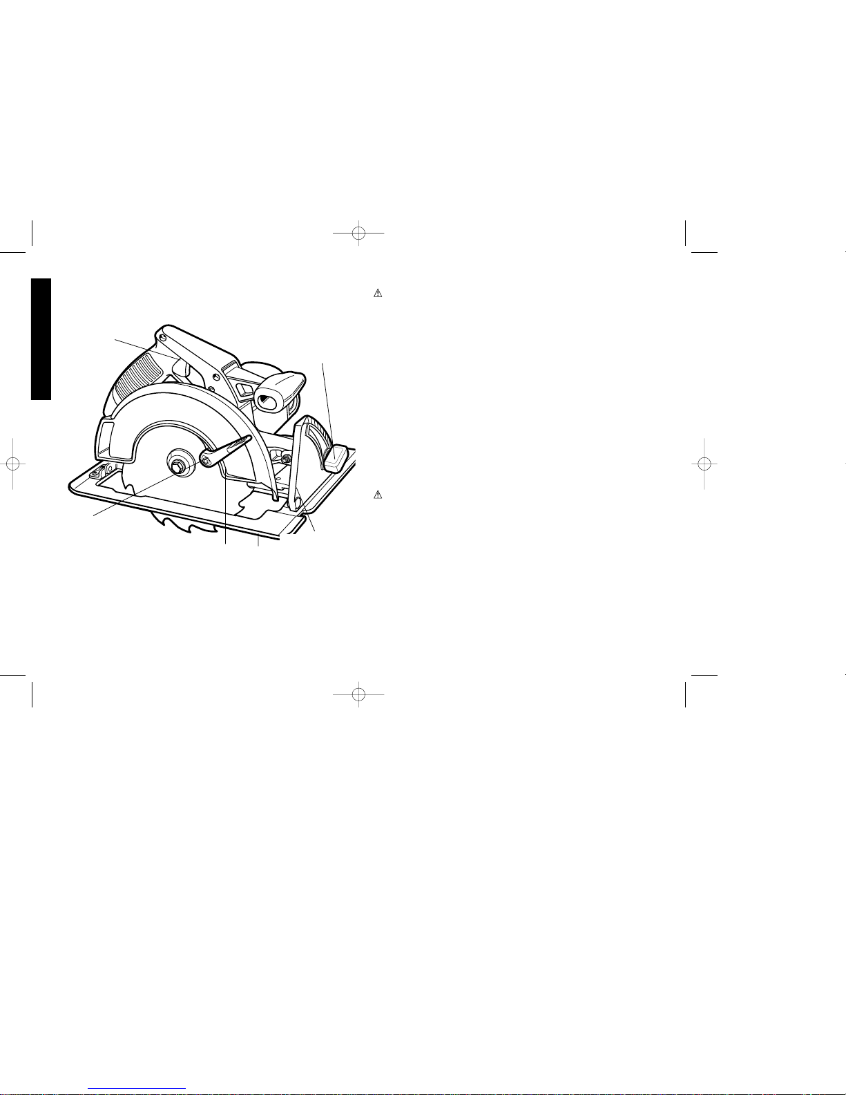
TRIGGER
SWITCH
RETRACTING
LEVER
LOWER GUARD
SHOE
QUADRANT KNOB
BEVEL
QUADRANT
617931-00QP350 Circular Saw NEW 4/15/03 1:01 PM Page 4
Page 4
tools to rain. Don't use power tools in damp or wet locations. Keep
work area well lit. Do not use tool in presence of flammable liquids
or gases.
• GUARD AGAINST ELECTRIC SHOCK. Prevent body contact
with grounded surfaces. For example; pipes, radiators, ranges,
and refrigerator enclosures.
• KEEP CHILDREN AWAY. Do not let visitors contact tool or
extension cord. All visitors should be kept away from work area.
• STORE IDLE TOOLS. When not in use, tools should be stored in
dry, and high or locked-up place - out of reach of children.
• DON'T FORCE TOOL. It will do the job better and safer at the rate
for which it was intended.
• USE RIGHT TOOL. Don't force small tool or attachment to do the
job of a heavy-duty tool. Don't use tool for purpose not intended.
• DRESS PROPERLY. Do not wear loose clothing or jewelry. They
can be caught in moving parts. Rubber gloves and non-skid
footwear are recommended when working outdoors. Wear
protective hair covering to contain long hair.
• USE SAFETY GLASSES. Also use face or dust mask if operation
is dusty.
• DON'T ABUSE CORD. Never carry tool by cord or yank it to
disconnect from receptacle. Keep cord from heat, oil, and sharp
edges.
• SECURE WORK. Use clamps or a vise to hold work. It's safer
than using your hand and it frees both hands to operate tool.
• DON'T OVERREACH. Keep proper footing and balance at all
times.
• MAINTAIN TOOLS WITH CARE. Keep tools sharp and clean for
better and safer performance. Follow instructions for lubricating
and changing accessories. Inspect tool cords periodically and if
damaged, have repaired by authorized service facility. Inspect
extension cords periodically and replace if damaged. Keep
handles dry, clean, and free from oil and grease.
1
English
• DISCONNECT OR LOCK OFF TOOLS when not in use, before
servicing, and when changing accessories, such as blades, bits,
cutters.
• REMOVE ADJUSTING KEYS AND WRENCHES. Form habit of
checking to see that keys and adjusting wrenches are removed
from tool before turning it on.
• AVOID UNINTENTIONAL STARTING. Don't carry tool with finger
on switch. Be sure switch is off when plugging in.
• EXTENSION CORDS. Make sure your extension cord is in good
condition. When using an extension cord, be sure to use one
heavy enough to carry the current your product will draw. An
undersized cord will cause a drop in line voltage resulting in loss
of power and overheating. The following table shows the correct
size to use depending on cord length and nameplate ampere
rating. If in doubt, use the next heavier gage. The smaller the
gage number, the heavier the cord.
Minimum Gage for Cord Sets
Volts Total Length of Cord in Feet
120V 0-25 26-50 51-100 101-150
240V 0-50 51-100 101-200 201-300
Ampere Rating
More Not more AWG
Than Than
0- 6 18 16 16 14
6 - 10 18 16 14 12
10- 12 16 16 14 12
12- 16 14 12 Not Recommended
• OUTDOOR USE EXTENSION CORDS. When operating a power
tool outside, use an outdoor extension cord marked “W-A” or “W.”
These cords are rated for outdoor use and reduce the risk of
electric shock.
• STAY ALERT. Watch what you are doing. Use common sense. Do
not operate tool when you are tired.
• CHECK DAMAGED PARTS. Before further use of the tool, a
guard or other part that is damaged should be carefully checked
617931-00QP350 Circular Saw NEW 4/15/03 1:01 PM Page 1
Page 5

English
2
to determine that it will operate properly and perform its intended
function. Check for alignment of moving parts, binding of moving
parts, breakage of parts, mounting, and any other conditions that
may affect its operation. A guard or other part that is damaged
should be properly repaired or replaced by an authorized service
center unless otherwise indicated elsewhere in this instruction
manual. Have defective switches replaced by authorized service
center. Do not use tool if switch does not turn it on and off.
ADDITIONAL SPECIFIC SAFETY RULES
• Hold tool by its gripping surfaces when performing an operation
where the cutting tool may contact hidden wiring or its own cord.
Contact with a “live” wire will make exposed metal parts of the tool
“live” and shock the operator.
WARNING: Some dust created by power sanding, sawing,
grinding, drilling, and other construction activities contains
chemicals known to cause cancer, birth defects or other
reproductive harm. Some examples of these chemicals are:
• lead from lead-based paints,
• crystalline silica from bricks and cement and other masonry
products, and
• arsenic and chromium from chemically-treated lumber (CCA).
Your risk from these exposures varies, depending on how often you
do this type of work. T o reduce your exposure to these chemicals:
work in a well ventilated area, and work with approved safety
equipment, such as those dust masks that are specially designed
to filter out microscopic particles.
• Avoid prolonged contact with dust from power sanding,
sawing, grinding, drilling, and other construction activities.
Wear protective clothing and wash exposed areas with soap
and water. Allowing dust to get into your mouth, eyes, or lay on the
skin may promote absorption of harmful chemicals.
WARNING: Use of this tool can generate and/or disperse dust,
which may cause serious and permanent respiratory or other injury.
Always use NIOSH/OSHA approved respiratory protection
appropriate for the dust exposure. Direct particles away from face
and body.
CAUTION: Wear appropriate hearing protection during use.
Under some conditions and duration of use, noise from this
product may contribute to hearing loss.
• The label on your tool may include the following symbols.
V..............volts
A..............amperes
Hz............hertz
W ............watts
min ..........minutes
............alternating current
........direct current
no............no load speed
............Class II Construction
…/min......revolutions or reciprocation per minute
............earthing terminal
............safety alert symbol
ADDITIONAL SAFETY INSTRUCTIONS FOR CIRCULAR SAWS
CAUTION: When cutting into walls, floors or wherever live
electrical wires may be encountered, DO NOT TOUCH ANY METAL
PARTS OF THE TOOL! Hold the tool only by insulated grasping
surfaces to prevent electric shock if you cut in the live wire.
• KEEP GUARDS IN PLACE AND IN WORKING ORDER. Never
wedge or tie lower guard open. Check operation of lower guard
before each use. Do not use if lower guard does not close briskly
over saw blade. CAUTION: If saw is dropped, lower guard may
be bent, restricting full return.
• KEEP BLADES CLEAN AND SHARP. Sharp blades minimize
stalling and kickback.
DANGER: Keep hands away from cutting area. Keep hands away
from blades. Do not reach underneath work while blade is rotating.
617931-00QP350 Circular Saw NEW 4/15/03 1:01 PM Page 2
Page 6

Do not attempt to remove cut material when blade is moving.
CAUTION: Blades coast after turn off.
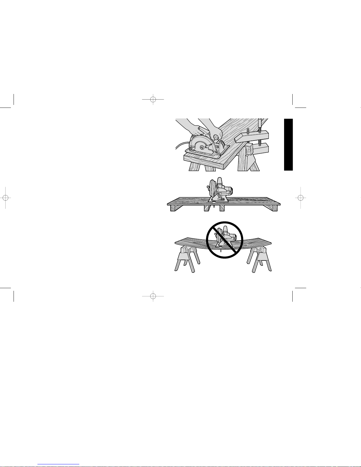
• SUPPORT LARGE PANELS. Large panels must be supported as
shown in Figure 16 to minimize the risk of blade pinching and
kickback. When cutting operation requires the resting of the saw
on the work piece, the saw shall be rested on the larger portion
and the smaller piece cut off.
• USE RIP FENCE. Always use a rip fence or straight edge guide
when ripping.
• GUARD AGAINST KICKBACK. Kickback occurs when the saw
stalls rapidly and is driven back towards the operator. Release
switch immediately if blade binds or saw stalls. Keep blades
sharp. Support large panels as shown in Figure 16. Use fence or
straight edge guide when ripping. Don’t force tool. Stay alertexercise control. Don’t remove saw from work during a cut while
the blade is moving.
• LOWER GUARD. Raise lower guard with the retracting handle.
• ADJUSTMENTS. Before cutting be sure depth and bevel
adjustments are tight.
• USE ONLY CORRECT BLADES IN MOUNTING. Do not use
blades with incorrect size holes. Never use defective or incorrect
blade washers or bolts.
• AVOID CUTTING NAILS. Inspect for and remove all nails from
lumber before cutting.
SA VE THESE INSTRUCTIONS
Motor
Be sure your power supply agrees with nameplate marking. 120
Volts AC only means your tool will operate on standard 60 Hz
household power. Do not operate AC tools on DC. A rating of 120
volts AC/DC means that you tool will operate on standard 60 Hz AC
3
English
or DC power. This information is printed on the nameplate. Lower
voltage will cause loss of power and can result in over-heating. All
Black & Decker tools are factory-tested; if this tool does not operate,
check the power supply.
Brushes
DISCONNECT PLUG FROM POWER SUPPLY BEFORE
SERVICING
Inspect carbon brushes regularly by unplugging tool, removing the
Brush Inspection Cap (Fig. 2) and withdrawing the brush assembly.
Keep brushes clean and sliding freely in their guides. Always replace
a used brush in the same orientation in the holder as it was prior to
removal. Carbon brushes have varying symbols stamped into their
sides, and if the brush is worn down to the line closest to the spring,
they must be replaced. Use only identical brushes. Always replace
both brushes. Use of the correct grade of brush is essential for
proper operation. New brush assemblies are available at your
authorized service center. The tool should be allowed to “run in” (run
at no load without a blade) for 10 minutes before use to seat new
brushes.
While “running in” DO NOT TIE, TAPE, OR OTHERWISE LOCK
THE TRIGGER SWITCH ON. HOLD BY HAND ONLY.
Adjustments and Setup
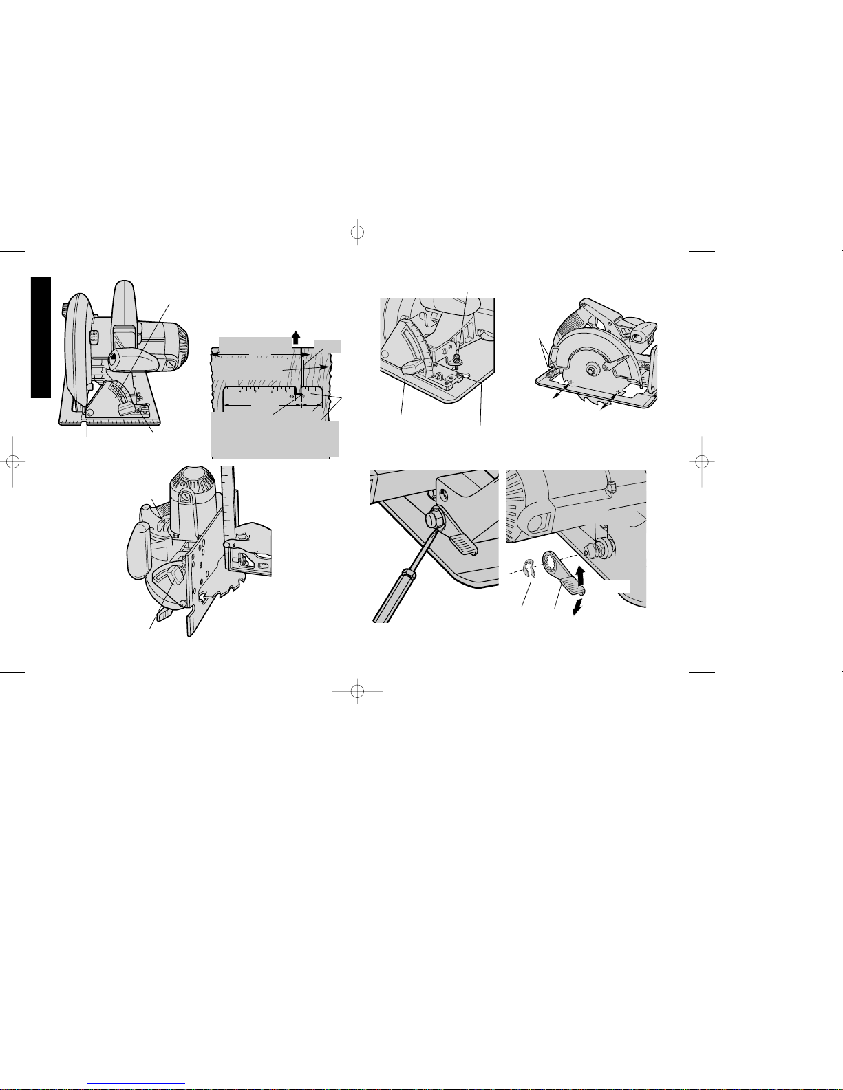
ATTACHING AND REMOVING BLADES
DISCONNECT PLUG FROM POWER SUPPLY.
To attach the blade, retract lower blade guard and place inner
clamp washer and blade on saw spindle with printed side of blade
out (teeth at bottom of blade pointing forward) (FIG. 1.) Place outer
clamp washer on saw spindle. The larger surfaces of both washers
must face the blade. Thread on blade clamping screw firmly by
hand to hold both blade washers in position.
Lightly depress the blade lock (FIG. 2) while turning the spindle
until the blade stops rotating. Tighten blade clamping screw
617931-00QP350 Circular Saw NEW 4/15/03 1:01 PM Page 3
Page 7
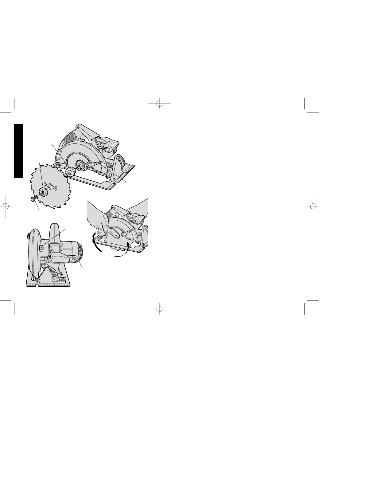
(clockwise) firmly with the blade wrench (FIG. 3).
NEVER ENGAGE BLADE LOCK WHILE SAW IS RUNNING, OR
ENGAGE IN AN EFFORT TO STOP THE TOOL. NEVER TURN
SWITCH ON WHEN BLADE LOCK IS ENGAGED. SERIOUS
DAMAGE TO YOUR SAW WILL RESULT.
When removing the blade, first unplug the saw. Engage the blade
lock and unscrew the blade clamping screw by turning it counterclockwise with the blade wrench.
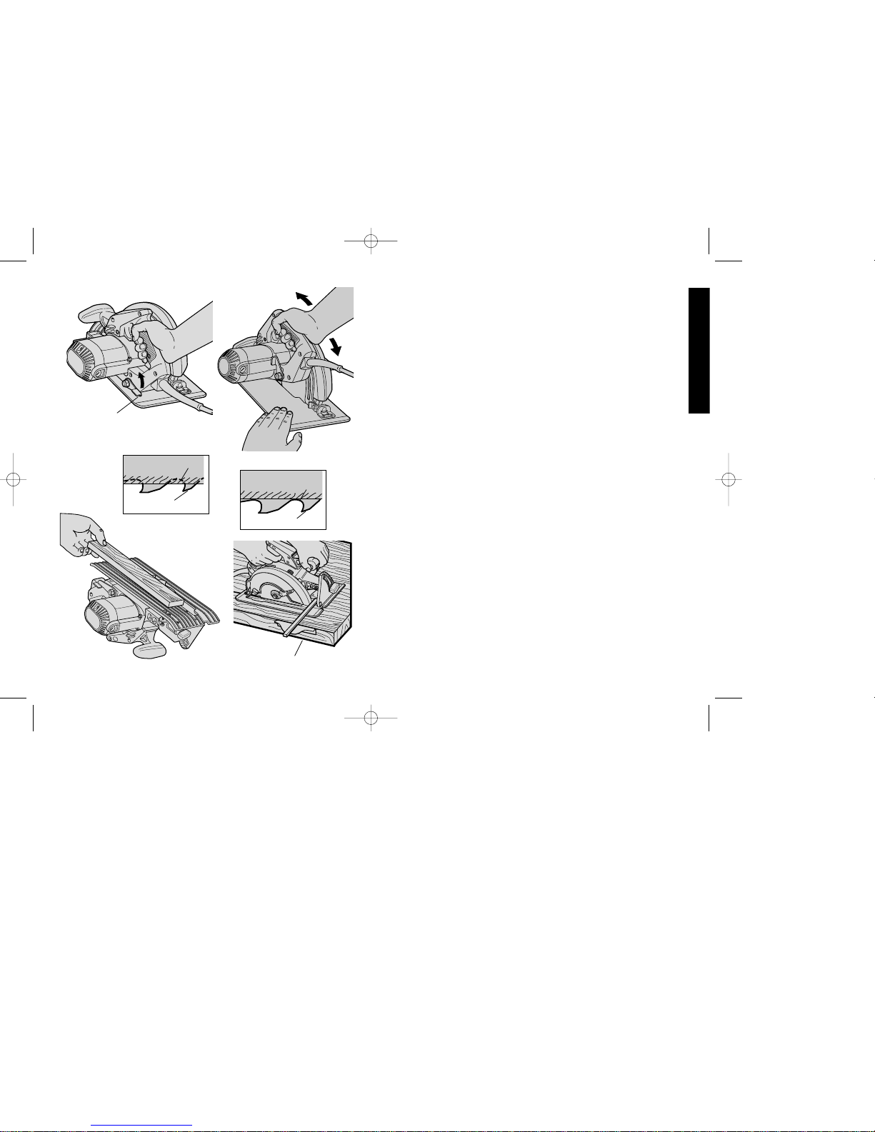
CUTTING DEPTH ADJUSTMENT
DISCONNECT PLUG FROM POWER SUPPLY.
Hold the saw firmly as shown in Figure 4. Loosen
(counterclockwise) the Depth Adjustment Lever and move shoe to
obtain the desired depth of cut, as shown in Figure 5. Make sure
the Depth Adjustment Lever has been retightened (clockwise)
before operating saw.
Your saw is equipped with a carbide tipped saw blade for long life
and efficient cutting.
For the most efficient cutting action using a carbide tipped saw
blade, set the depth adjustment so that about one half of a tooth
projects below the surface of the wood to be cut. The height of a
whole tooth is the distance from the tip of the tooth to the bottom of
the gullet in front of it. Study Figures 5A and 5B to determine what
one half tooth means. (5A shows one half tooth projecting below
the surface and figure 5B shows a whole tooth projecting below the
surface.)
Setting the saw at the proper cutting depth keeps blade friction to a
minimum, removes sawdust from between the blade teeth, results in
cooler, faster sawing and reduces the chance of kickback.
A method of checking for the correct cutting depth is shown in Figure
6. Lay a piece of the material you plan to cut along the side of the
blade, as shown in the figure, and observe how much tooth projects
beyond the material.
NOTE: When using a non carbide tipped blade, make an exception
to the above procedure and allow a full tooth to project below the
material, as shown in Figure 5B.
4
English
FIG. 1
INNER
CLAMP
WASHER
OUTER
CLAMP
WASHER
BLADE CLAMPING SCREW
RETRACTING
LEVER
BLADE
LOCK
BRUSH
INSPECTION
CAP
FIG. 2
FIG. 3
TIGHTEN
LOOSEN
617931-00QP350 Circular Saw NEW 4/15/03 1:01 PM Page 4
Page 8
5
English
FIG. 4
DEPTH
ADJUSTMENT
LEVER
FIG. 5
FIG. 6
GULLETSURFACE
OF WOOD
FIG. 7
RIP FENCE
TIP OF TOOTH
TIP OF TOOTH
FIG. 5A
FIG. 5B
GULLET
SURFACE
OF WOOD
BEVEL ANGLE ADJUSTMENT
DISCONNECT THE SAW FROM THE POWER SUPPLY.
The full range of the Bevel Adjustment is from 0 TO 50 DEGREES.
The quadrant is graduated in increments of 5 degrees.
On the front of the saw is a bevel angle adjustment mechanism
(Figure 8) consisting of a calibrated quadrant and a lever or knob. T o
set the saw for a bevel cut, loosen (counterclockwise) the quadrant
knob and tilt shoe to the desired angle by aligning the pointer with the
desired angle mark. Retighten knob firmly (clockwise).
NOTE: The quadrant pointer, located between the quadrant knob
and the quadrant, can be adjusted after loosening its screw.
Retighten firmly after adjustment.
KERF INDICATOR
The front of the saw shoe has a kerf indicator (Figure 8) for vertical
and bevel cutting. This indicator enables you to guide the saw along
cutting lines penciled on the material being cut. The indicator lines
up with the left (inner) side of the saw blade, which makes the slot or
“kerf” cut by the moving blade fall to the right of the indicator. Guide
along the penciled cutting line so that the kerf falls into the waste or
surplus material – See Figure 9. Figure 9 shows the dimensions of
the shoe. The right dimension is 1-1/2” (standard 2x lumber).
SHOE ALIGNMENT
Your saw has been set at the factory for accurate vertical cuts (a 90
degree angle between the bottom of the shoe and the blade). The
edge of the shoe has also been set parallel to the blade so that it
will not bind when using an edge guide. If the saw should ever need
adjustment, it may be done as follows:
ADJUSTING FOR 90° CUTS
1. DISCONNECT PLUG FROM POWER SUPPLY.
2. Adjust the saw to 0° bevel.
3. Place saw on blade side (Fig. 10). Retract blade guard.
4. Loosen quadrant lever or knob (Fig. 10). Place a square
against the blade and shoe to adjust the 90° setting.
617931-00QP350 Circular Saw NEW 4/15/03 1:01 PM Page 5
Page 9
6
English
FIG. 12
SCREWS
FIG. 13
FIG. 14
LOCK
NUT
LOCK
RING
LEVER
TIGHTEN
LOOSEN
45
30
2
2
.
5
15
0
FIG. 11
SCREWS
QUADRANT
KNOB
ADJUSTMENT SCREW
FIG. 8
QUADRANT
KERF
INDICATOR
FIG. 9
GUIDE ALONG PENCILED
CUTTING LINE SO KERF
FALLS IN WASTE STOCK
DIRECTION OF CUT
KERF
QUADRANT
KNOB
WASTE OR
SURPLUS STOCK
Align left side of
saw blade
with“45” mark, as
shown, for 45°
bevel cutting
5 "
1-1/2"
Align left side of
saw blade with
“0” mark for
straight cutting
QUADRANT KNOB
FIG. 10
DESIRED WIDTH
OF STOCK
CORD
KEEPER
617931-00QP350 Circular Saw NEW 4/15/03 1:01 PM Page 6
Page 10
5. Loosen the hex nut and move the adjustment screw so that the
shoe will stop at the proper angle as shown in Figure 11. Lock
the screw in place by tightening the hex nut.
6. It may be necessary to adjust the quadrant angle pointer to line
up on “O” after shoe has been adjusted.
ADJUSTING THE SHOE PARALLEL TO THE BLADE
(Your saw is adjusted at the factory so that the blade and shoe are
parallel. If these parts become misaligned, adjust as follows.)
1. Disconnect plug from power supply.
2. Loosen the (2) screws at the adjusting bracket at the rear of
the shoe, as shown in Figure 12.
3. Adjust the shoe until it is parallel to the blade by measuring
from the edge of the shoe to the blade, front & rear. You can
measure from the outside edge of the blade to the shoe as
shown in Figure 12 or from the inner edge of the blade to the
wider part of the shoe. (Do not measure from the tips of any
saw blade teeth.)
4. When shoe is parallel, tighten all screws.
ADJUSTING DEPTH ADJUSTMENT LEVER
It may be desirable to adjust the Depth Adjustment. (It will
sometimes hit the shoe before tightening or loosening completely.)
To adjust lever, follow the steps below.
1. Disconnect plug from power supply.
2. Using a small screwdriver, pry the lock ring off, as shown in
Figure 13.
3. Remove the lever and rotate it in the desired direction about 1/8
revolution. (More or less as necessary.)
4. Reinstall the lever and insert the lock ring with concave side
against lever to hold it in place. (Figure 14)
7
English
FIG. 15
FIG. 16
SUPPORT WORK
NEAR CUT
FIG. 17
WRONG -
MATERIAL BENDS ON
BLADE CAUSING HEAVY
LOADS OR KICKBACK.
RIGHT
617931-00QP350 Circular Saw NEW 4/15/03 1:01 PM Page 7
Page 11

8
support cantilevered and overhanging material. Use caution when
sawing material from below.
Be sure saw is up to full speed before blade contacts material to be
cut. Starting saw with blade against material to be cut or pushed
forward into kerf can result in kickback.
Push the saw forward at a speed which allows the blade to cut
without laboring. Hardness and toughness can vary even in the
same piece of material, and knotty or damp sections can put a
heavy load on the saw. When this happens, push the saw more
slowly, but hard enough to keep it working without much decrease
in speed.
Forcing the saw can cause rough cuts, inaccuracy, kickback and
over-heating of the motor.
Should your cut begin to go off the line, don’t try to force it back on.
Release the switch and allow blade to come to a complete stop.
Then you can withdraw the saw, sight anew, and start a new cut
slightly inside the wrong one. In any event, withdraw the saw if you
must shift the cut. Forcing a correction inside the cut can stall the
saw and lead to kickback. IF SAW STALLS, RELEASE THE
English
Operation
SWITCH
Pull the trigger switch to turn the motor “ON”. Releasing the trigger
turns the motor “OFF”. This tool has no provision to lock the switch
in the “ON” position, and should never be locked “ON” in any way.
WORKPIECE SUPPORT
Figure 15 shows proper sawing position. Note that hands are kept
away from cutting area, and power cord is positioned clear of the
cutting area so that it will not get caught or hung up on the work.
To avoid kickback, DO support board or panel NEAR the cut,
(Figure 16). DON’T support board or panel away from the cut
(Figure 17).
When operating the saw, keep the cord away from the cutting area
and prevent it from becoming hung up on the work piece. Note that
a special Cord Keeper has been provided on the tool’s handle. (See
Fig. 10 on page 6.) Press the cord firmly into the cord keeper to
keep it out of the way but in sight so you know where it is at all
times.
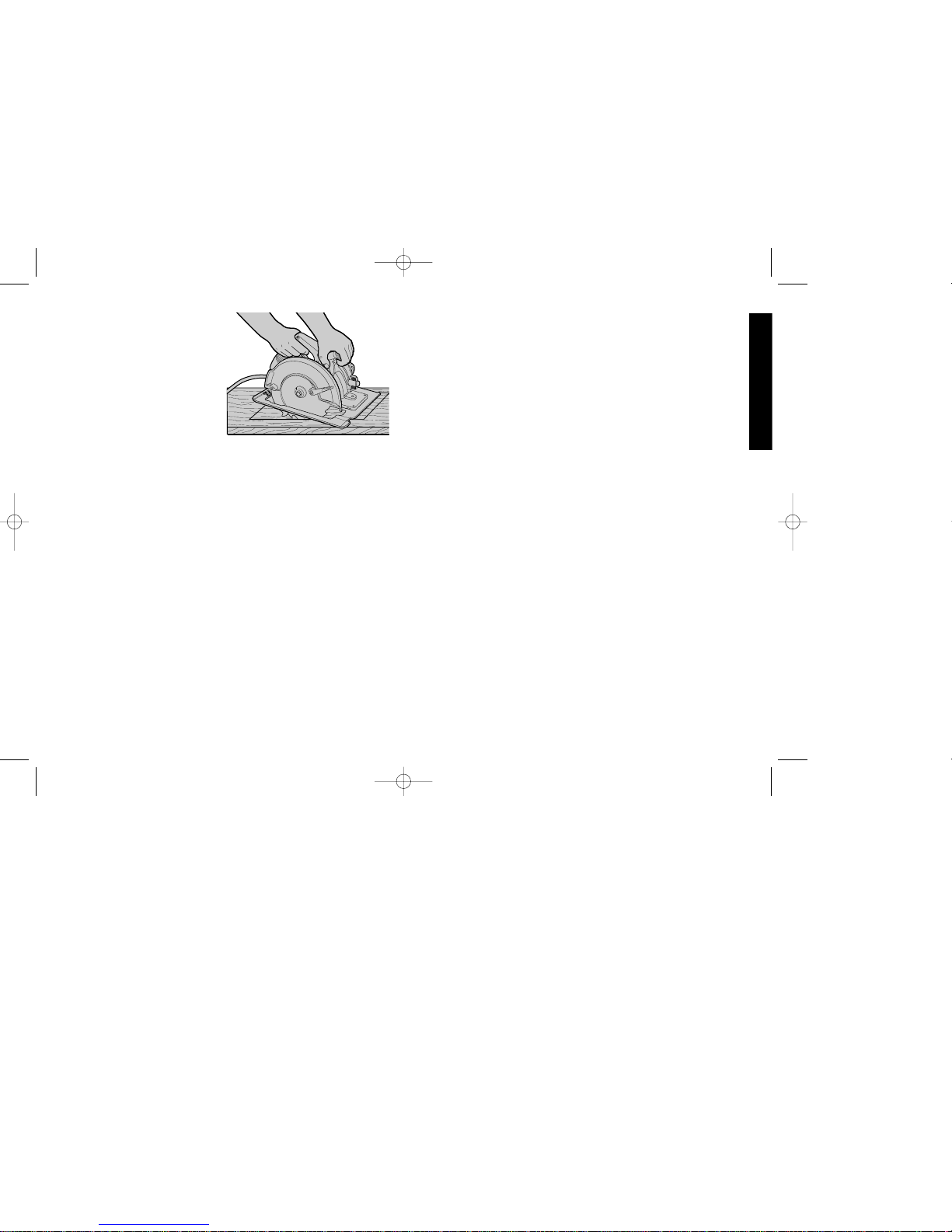
WARNING: It is important to support the work properly and to
hold the saw firmly to prevent loss of control which could cause
personal injury; Figure 18 illustrates typical hand support of the saw.
ALWAYS DISCONNECT SA W BEFORE MAKING ANY
ADJUSTMENTS! Place the work with its “good” side – the one on
which appearance is most important – down. The saw cuts upward,
so any splintering will be on the work face that is up when you saw it.
CUTTING
Support the work so that the cut will be on your right. Place the
wider portion of the saw shoe on that part of the work piece which
is solidly supported, not on the section that will fall off when the cut
is made. As examples, Figure 18 illustrates the RIGHT way to cut
off the end of a board, and Figure 19 the WRONG way. Always
clamp work. Don’t try to hold short pieces by hand! Remember to
FIG. 18 FIG. 19
WRONG
617931-00QP350 Circular Saw NEW 4/15/03 1:01 PM Page 8
Page 12
TRIGGER AND BACK THE SAW
UNTIL IT IS LOOSE. BE SURE
BLADE IS STRAIGHT IN THE
CUT AND CLEAR OF THE
EDGE BEFORE RESTARTING.
As you finish a cut, release the
trigger and allow the blade to
stop before lifting the saw from
the work. As you lift the saw, the
spring-tensioned telescoping
guard will automatically close
under the blade. Remember the blade is exposed until this occurs,
never reach under the work for any reason whatsoever. When you
have to retract the telescoping guard manually (as is necessary for
starting pocket cuts) always use the retracting lever.
NOTE: When cutting thin strips, be careful to ensure that small
cutoff pieces don’t hang up on inside of lower guard.
When ripping (cutting with the grain) the use of a rip fence is
recommended. (See Figure 7)
POCKET CUTTING
DISCONNECT PLUG FROM POWER SUPPLY WHEN MAKING
THIS OR ANY OTHER ADJUSTMENT. Adjust saw shoe so blade
cuts at desired depth. Tilt saw forward and rest front of the shoe on
material to be cut. Using the retracting lever, retract blade guard to
an upward position. Lower rear of shoe until blade teeth almost
touch cutting line. Now release the blade guard (its contact with the
work will keep it in position to open freely as you start the cut)
(Figure 20). Start the motor and gradually lower the saw until its
shoe rests flat on the material to be cut. Advance saw along the
cutting line until cut is completed. Release trigger and allow blade
to stop completely before withdrawing the blade from the material.
When starting each new cut, repeat as above. Never tie the blade
guard in a raised position.
Kickback
When the saw blade becomes pinched or twisted in the cut, kickback
can occur. The saw is thrust rapidly back toward the operator . When
the blade is pinched or bound tightly by the kerf closing down, the
blade stalls and the motor reaction drives the unit backward. When
the blade becomes twisted or misaligned in the cut, the teeth at the
back edge of the blade can dig into the top surface of the wood
causing the blade to climb out of the kerf and jump back toward the
operator.
Kickback is more likely to occur when any of the following conditions
exist.
1. IMPROPER WORKPIECE SUPPORT
A. Sagging or improper lifting of the cut off piece causing
pinching of the blade.
B. Cutting through material supported at the outer ends only
(see Figure 17). As the material weakens it sags, closing
down the kerf and pinching the blade.
C. Cutting off a cantilevered or overhanging piece of material
from the bottom up in a vertical direction. The falling cut off
piece can pinch the blade.
D. Cutting off long narrow strips (as in ripping). The cut off strip
can sag or twist closing the kerf and pinching the blade.
E. Snagging the lower guard on a surface below the material
being cut momentarily reducing operator control. The saw
can lift partially out of the cut increasing the chance of blade
twist.
2. IMPROPER DEPTH OF CUT SETTING ON SAW
Using the saw with an excessive depth of cut setting increases
loading on the unit and susceptibility to twisting of the blade in
the kerf. It also increases the surface area of the blade
avaliable for pinching under conditions of kerf close down.
3. BLADE TWISTING (MISALIGNMENT IN CUT)
A. Pushing harder to cut through a knot, a nail, or a hard grain
9
English
FIG. 20
617931-00QP350 Circular Saw NEW 4/15/03 1:01 PM Page 9
Page 13

procedures and techniques that will minimize the occurrence of
kickback.
Blades
A dull blade will cause slow, inefficient cutting, overload on the saw
motor, excessive splintering and increase the possibility of
kickback. It is a good practice to keep extra blades on hand so that
sharp blades are available while the dull ones are being sharpened
(See “SAWS-SHARPENING” in the Yellow Pages). In fact, many
lower priced blades can be replaced with new ones at very little
cost over the sharpening price.
Hardened gum on the blade will slow down the cutting. This gum
can best be removed with trichlorethylene, kerosene, turpentine or
oven cleaner.
Black & Decker manufactures a complete line of 7-1/4” (180mm)
diameter saw blades and they are available from your authorized
service center.
VISUALLY EXAMINE CARBIDE BLADES BEFORE USE.
REPLACE IF DAMAGED.
Cleaning and Lubrication
Use only mild soap and a damp cloth to clean the tool. Never let any
liquid get inside the tool; never immerse any part of the tool into a
liquid.
Accesories
Recommended accessories for use with your tool are available at
extra cost from your distributor or authorized service center.
CAUTION: use of any non-recommended accessory may be
hazardousl.
10
area can cause the blade to twist.
B. Trying to turn the saw in the cut (trying to get back on the
marked line) can cause blade twist.
C. Extended reach or operating saw with poor body control
(out of balance), can result in twisting the blade.
D. Changing hand grip or body position while cutting can result
in blade twist.
E. Backing unit up to clear blade can lead to twist if not done
carefully.
4. MATERIALS THAT REQUIRE EXTRA ATTENTION
A. Wet lumber
B. Green lumber (material freshly cut or not kiln dried)
C. Pressure treated lumber (material treated with
preservatives or anti-rot chemicals)
5. USE OF DULL OR DIRTY BLADES
Dull blades cause increased loading of the saw. To
compensate, an operator will usually push harder which
further loads the unit and promotes twisting of the blade in the
kerf. Worn blades may also have insufficient body clearance
which increases the chance of binding and increased loading.
6. LIFTING THE SAW WHEN MAKING BEVEL CUTS
Bevel cuts require special operator attention to proper cutting
techniques – especially guidance of the saw. Both blade angle
to the shoe and greater blade surface in the material increase
the chance for binding and misalignment (twist) to occur.
7.RESTARTING A CUT WITH THE BLADE TEETH JAMMED
AGAINST THE MATERIAL
The saw should be brought up to full operating speed before
starting a cut or restarting a cut after the unit has been
stopped with the blade in the kerf. Failure to do so can cause
stalling and kickback.
Any other conditions which could result in pinching, binding,
twisting, or misalignment of the blade could cause kickback. Refer
to the sections on “Adjustments And Set-Up” and “Operation” for
English
617931-00QP350 Circular Saw NEW 4/15/03 1:01 PM Page 10
Page 14

11
Important!
To assure product SAFETY and RELIABILITY, repairs,
maintenance and adjustment (including brush inspection and
replacement) should be performed by authorized service centers or
other qualified service organizations, always using identical
replacement parts
Service Information
All Black & Decker Service Centers are staffed with trained
personnel to provide customers with efficient and reliable power
tool service. Whether you need technical advice, repair, or genuine
factory replacement parts, contact the Black & Decker location
nearest you. To find your local service location, refer to the yellow
page directory under "Tools—Electric", call:1-800-544-6986 or visit
www.blackanddecker.com
Limited Three Year Warranty
Black & Decker (U.S.) Inc. warrants this product for three years
against any defects in material or workmanship. The defective
product will be replaced or repaired at no charge in either of two
ways.
The first, which will result in exchanges only, is to return the product
to the retailer from whom it was purchased (provided that the store
is a participating retailer). Returns should be made within the time
period of the retailer’s policy for exchanges (usually 30 to 90 days
after the sale). Proof of purchase may be required. Please check
with the retailer for their specific return policy regarding returns that
are beyond the time set for exchanges.
The second option is to take or send the product (prepaid) to a
Black & Decker owned or authorized Service Center for repair or
replacement at our option. Proof of purchase may be required.
Black & Decker owned and authorized Service Centers are listed
under "Tools-Electric" in the yellow pages of the phone directory
and available on our website www.blackanddecker.com.
This warranty does not apply to accessories. This warranty gives
you specific legal rights and you may have other rights which vary
from state to state. Should you have any questions, contact the
manager of your nearest Black & Decker Service Center.
See ‘Tools-Electric’
– Yellow Pages –
for Service & Sales
Black & Decker (U.S.) Inc.,
701 E. Joppa Rd.
Towson, MD 21286 U.S.A.
617931-00QP350 Circular Saw NEW 4/15/03 1:01 PM Page 11
Page 15

12
Français
POUR TOUT RENSEIGNEMENT SUPPLÉMENTAIRE SUR CET
OUTIL OU TOUT AUTRE OUTIL QUAMTUM PRO, COMPOSER
SANS FRAIS LE NUMÉR SUIVANT.
1 800 544-6986
Importantes mesures de sécurité
AVERTISSEMENT : Afin de réduire les risques d’incendie, de
secousses électriques ou de blessures lorsqu’on utilise des outils
électriques, il faut toujours respecter les mesures de sécurité
suivantes.
LIRE TOUTES LES DIRECTIVES.
Mise à la terre
L’outil devrait être mis à la terre lorsqu’on s’en sert afin de protéger
l’utilisateur contre les secousses électriques. Le conducteur vert
(ou vert et jaune) du cordon sert de mise à la terre. Ne jamais relier
le conducteur vert (ou vert et jaune) à une borne sous tension.
Il faut relier les deux contacts de mise à la terre et la fiche de mise à
la terre à une mise à la terre permanente, comme une prise bien
mise à la terreIl n’existe aucun adaptateur pour une fiche semblable
à celle.
Mesures de sécurité pour tous les outils
• BIEN DÉGAGER LA SURFACE DE TRAVAIL. Des surfaces et
des établis encombrés peuvent être la cause de blessures.
• TENIR COMPTE DU MILIEU DE TRAVAIL. Protéger les outils
électriques de la pluie. Ne pas s’en servir dans des endroits
humides ou mouillés. Bien éclairer la surface de travail. Ne pas se
servir de l’outil en présence de liquides ou de vapeurs
inflammables.
• SE PROTÉGER CONTRE LES SECOUSSES ÉLECTRIQUES.
Éviter tout contact avec des objets mis à la terre, comme des
tuyaux, radiateurs, cuisinières, réfrigérateurs et autres objets du
genre.
• ÉLOIGNER LES ENFANTS. Tous les visiteurs doivent être tenus
à l’écart de l’aire de travail et il faut les empêcher de toucher à
l’outil ou au cordon de rallonge.
• RANGER LES OUTILS INUTILISÉS. Il faut ranger les outils dans
INTERRUPTEUR
À DÉTENTE
RESSORT DE
RAPPEL
PROTÈGE-LAME INFÉRIEUR
PATIN
BOUTON OU LEVIER
DU SECTEUR
SECTEUR
617931-00QP350 Circular Saw NEW 4/15/03 1:01 PM Page 12
Page 16

13
Français
un endroit sec, situé en hauteur ou fermé à clé, hors de la portée
des enfants.
• NE JAMAIS FORCER L’OUTIL. Afin d’obtenir un rendement sûr
et efficace, utiliser l’outil à son rendement nominal.
• UTILISER L’OUTIL APPROPRIÉ. Ne jamais exiger d’un petit outil
ou d’un accessoire le rendement d’un outil de fabrication plus
robuste. Se servir de l’outil selon l’usage prévu.
• PORTER DES VÊTEMENTS APPROPRIÉS. Éviter de porter des
vêtements amples et des bijoux qui peuvent être happés par les
pièces en mouvement. Porter des gants de caoutchouc et des
chaussures à semelle antidérapante pour travailler à l’extérieur.
Protéger la chevelure si elle est longue.
• PORTER DES LUNETTES DE SÉCURITÉ. Porter également un
masque respiratoire si le travail de coupe produit de la poussière.
• NE PAS MANIPULER LE CORDON DE FAÇON ABUSIVE. Ne
pas transporter l’outil par le cordon ni tirer sur ce dernier pour le
débrancher de la prise. Éloigner le cordon des sources de chaleur,
des flaques d’huile et des arêtes tranchantes.
• ASSUJETTIR LA PIÈCE. Immobiliser la pièce à l’aide de brides
ou d’un étau. On peut alors se servir des deux mains pour faire
fonctionner l’outil, ce qui est plus sûr.
• NE PAS DÉPASSER SA PORTÉE. Toujours demeurer dans une
position stable et garder son équilibre.
• PRENDRE SOIN DES OUTILS. Conserver les outils propres pour
qu’ils donnent un rendement supérieur et sûr. Suivre les directives
concernant la lubrification et le remplacement des accessoires.
Inspecter régulièrement le cordon de l’outil et le faire réparer au
besoin à un atelier d’entretien autorisé. Inspecter régulièrement les
cordons de rallonge et les remplacer lorsqu’ils sont endommagés.
S’assurer que les poignées sont toujours propres, sèches et libres
de toute tache d’huile ou de graisse.
• DÉBRANCHER OU VERROUILLER EN POSITION HORS
TENSION LES OUTILS NON UTILISÉS. Respecter cette mesure
lorsqu’on ne se sert pas de l’outil, ou qu’on doit le réparer ou en
changer un accessoire (comme une lame, un foret ou un couteau).
• ENLEVER LES CLÉS DE RÉGLAGE. Prendre l’habitude de
vérifier si les clés de réglage ont été retirées avant de faire
démarrer l’outil.
• ÉVITER LES DÉMARRAGES ACCIDENTELS. Ne pas laisser le
doigt sur l’interrupteur lorsqu’on transporte l’outil. S’assurer que
l’interrupteur est à la position hors circuit lorsqu’on branche l’outil.
• CORDONS DE RALLONGE. S’assurer que le cordon de rallonge
est en bon état. Lorsqu’on se sert d’un cordon de rallonge,
s’assurer qu’il est de calibre approprié pour la tension nécessaire
au fonctionnement de l’outil. L’utilisation d’un cordon de calibre
inférieur occasionne une baisse de tension entraînant une perte de
puissance et la surchauffe. Le tableau suivant indique le calibre
approprié selon la longueur du cordon et les mentions de la plaque
signalétique de l’outil. En cas de doute, utiliser un cordon de calibre
supérieur. Le chiffre indiquant le calibre est inversement
proportionnel au calibre du cordon.
Calibre minimal des cordons de rallonge
Longueur totale du cordon
25 ft. 50 ft. 75 ft. 100 ft. 125 ft. 150 ft. 175 ft.
7.6 m 15.2 m 22.9 m 30.5 m 38.1 m 45.7 m 53.3 m
Intensité
18 AWG 18 AWG 16 AWG 16 AWG 14 AWG 14 AWG 12 AWG
• CORDONS DE RALLONGE PRÉVUS POUR L’EXTÉRIEUR.
Lorsque l’outil est utilisé à l’extérieur, ne se servir que d’un cordon
de rallonge conçu pour l’extérieur et portant la mention appropriée.
• DEMEURER VIGILANT. Travailler avec vigilance et faire preuve
de bon sens. Ne pas se servir de l’outil lorsqu’on est fatigué.
• VÉRIFIER LES PIÈCES ENDOMMAGÉES. Avant de continuer à
utiliser l’outil, il faut vérifier si le protecteur ou toute autre pièce
endommagée remplit bien la fonction pour laquelle il a été prévu.
Vérifier l’alignement et les attaches des pièces mobiles, le degré
d’usure des pièces et leur montage, ainsi que tout autre facteur
617931-00QP350 Circular Saw NEW 4/15/03 1:01 PM Page 13
Page 17

14
susceptible de nuire au bon fonctionnement de l’outil. Faire réparer
ou remplacer tout protecteur ou toute autre pièce endommagée
dans un centre de service autorisé, sauf si le présent guide fait
mention d’un avis contraire. Confier le remplacement de tout
interrupteur défectueux à un centre de service autorisé. Ne jamais
se servir d’un outil dont l’interrupteur est défectueux.
Mesures de sécurité additionnelles
relatives aux scies circulaires
• MISE EN GARDE : Lorsqu’on coupe dans les murs, les planchers
ou tout autre endroit où peuvent se trouver des fils sous tension,
NE PAS TOUCHER AUX COMPOSANTS MÉTALLIQUES DE
L’OUTIL. Ne le saisir que par ses surfaces en plastique afin de se
protéger des secousses électriques si on entre en contact avec
un fil sous tension.
• S’ASSURER QUE LES PROTECTEURS EN PLACE ET EN
ÉTAT DE FONCTIONNEMENT. Ne jamais bloquer ni attacher le
protecteur inférieur en position ouverte. Vérifier le fonctionnement
du protecteur inférieur avant chaque utilisation. Ne pas e servir de
l’outil lorsque le protecteur inférieur ne se ferme pas complètement
sur la lame. MISE EN GARDE : Si la scie tombe, le protecteur
inférieur peut se tordre et ne plus se refermer complètement.
• S’ASSURER QUE LES LAMES SONT PROPRES ET
AFFÛTÉES. Des lames affûtées minimisent les risques de calage
et de rebond.
• DANGER : ÉLOIGNER LES MAINS DE LA ZONE DE COUPE.
Éloigner les mains de la lame. Ne pas placer les mains sous la
pièce à découper pendant les travaux lorsque la lame tourne. Ne
pas tenter de retirer du matériau lorsque la lame est en
mouvement. MISE EN GARDE : La lame continue de tourner
après la mise hors tension.
• SOUTENIR LES GRANDS PANNEAUX. Il faut soutenir les
panneaux de grandes dimensions de la façon illustrée à la figure
16 afin de minimiser les risques de coincement de la lame et de
rebond. Lorsqu’il faut déposer la scie contre la pièce à découper
pendant les travaux, il faut la déposer sur la partie la plus large du
matériau et découper la plus petite partie.
• UTILISER UN GUIDE DE REFENTE. Toujours utiliser un guide
de refente ou un guide à rebord droit lors des coupes en refente.
• SE PROTÉGER CONTRE LES RISQUES DE REBOND. Le
rebond se produit lorsque la lame se bloque rapidement et qu’elle
ressort du matériau vers l’utilisateur. Il faut relâcher
immédiatement l’interrupteur en cas de blocage ou de calage.
Maintenir les lames bien affûtées. Soutenir les panneaux de
grandes dimensions de la façon illustrée à la figure 16. Utiliser un
guide de refente ou à rebord droit lors des coupes en refente. Ne
pas forcer l’outil. Rester vigilant; maîtriser la situation. Ne pas
retirer la scie du matériau lorsque la scie est en mouvement.
• PROTECTEUR INFÉRIEUR. Utiliser le ressort de rappel pour
soulever le protecteur inférieur.
• RÉGLAGES. S’assurer que les réglages de coupe en biseau et de
profondeur sont bien serrés avant la coupe.
• LORS DU MONTAGE, UTILISER SEULEMENT DES LAMES
APPROPRIÉES. Ne pas utiliser une lame dont le diamètre du trou
n’est pas approprié. Ne jamais utiliser des rondelles ou des
boulons de lames défectueux ou de dimensions inappropriées.
• ÉVITER DE COUPER DES CLOUS. Examiner la pièce à
découper pour s’assurer qu’elle ne renferme aucun clou avant les
travaux. Le cas échéant, les retirer.
• MISE EN GARDE : Certaines essences de bois renferment des
agents de conservation (comme de l’arséniate de cuivre et de
chrome) qui peuvent être toxiques. Lorsqu’on doit couper de tels
matériaux, prendre des mesures supplémentaires afin d’éviter
d’inhaler les vapeurs toxiques et de minimiser les contacts avec la
peau.
CONSERVER CES MESURES.
Français
617931-00QP350 Circular Saw NEW 4/15/03 1:01 PM Page 14
Page 18

Moteur
Veiller à ce que la tension d’alimentation soit conforme aux
exigences de la plaque signalétique de l’outil. La mention
220 volts c.a./c.c. signifie que l’outil fonctionne également sur une
alimentation en courant alternatif ou continu. Une baisse de tension
entraîne une perte de puissance et la surchauffe. Tous les outils
sont essayés avant de quitter l’usine. Lorsque celui-ci refuse de
fonctionner, vérifier la source de courant électrique.
Balais
DÉBRANCHER L’OUTIL AVANT D’EN FAIRE L’ENTRETIEN.
Inspecter régulièrement les balais en charbon en débranchant
d’abord la scie, en retirant le couvercle d’inspection des balais (fig. 2)
et en sortant l’assemblage-balais. S’assurer que les balais sont
propres et qu’ils glissent bien dans leurs guides. Toujours remplacer
les balais usés par des balais placés dans le même sens dans le
porte-balai. Différents symboles sont inscrits sur les côtés des balais
en charbon. Lorsque le balai est usé jusqu’à la ligne la plus près du
ressort, il faut le remplacer. N’utiliser que des balais de rechange
identiques. Il faut toujours remplacer les deux balais. Il faut utiliser
des balais de même qualité pour s’assurer du bon fonctionnement du
frein électrique (dans le cas des modèles qui en sont pourvus). Le
centre de service de la région vend des balais de rechange. Il faut
laisser l’outil fonctionner à vide (sans charge et sans lame) pendant
dix minutes avant de l’utiliser afin de permettre aux nouveaux balais
de s’installer. Cette mesure est des plus importantes car les scies
dotées de freins électriques peuvent fonctionner de façon irrégulière
jusqu’à ce que les balais se placent.
Pendant le fonctionnement à vide de la scie, NE PAS ATTACHER,
COLLER NI BLOQUER DE TOUTE AUTRE FAÇON
L’INTERRUPTEUR À DÉTENTE. LE TENIR À LA MAIN
SEULEMENT.
Réglage et installation
INSTALLATION ET RETRAIT DE LA LAME
DÉBRANCHER LA SCIE.
Pour installer la lame, escamoter le protège-lame inférieur et placer
la rondelle de fixation interne et la lame sur l’arbre de la scie en
plaçant la face imprimée de la lame vers l’extérieur (les dents au
bas de la lame pointant vers l’avant) (fig. 1). Installer la rondelle de
fixation externe de la lame sur l’arbre de la scie. Les surfaces larges
des deux rondelles doivent se trouver sur la lame. Serrer fermement
à la main la vis de fixation de la lame de manière à retenir les deux
rondelles en place.
Enfoncer légèrement le dispositif de verrouillage de la lame (fig. 2) en
faisant tourner l’arbre jusqu’à ce que la lame s’immobilise. Serrer
fermement (dans le sens horaire) la vis de fixation de la lame avec
la clé de la scie (fig. 3).
NE JAMAIS ENGAGER LE DISPOSITIF DE VERROUILLAGE DE
LA LAME LORSQUE LA SCIE FONCTIONNE NI POUR
IMMOBILISER L’OUTIL. NE JAMAIS METTRE LA SCIE EN
MARCHE LORSQUE LE DISPOSITIF DE VERROUILLAGE DE LA
LAME EST EN PLACE, AU RISQUE DE GRAVEMENT
ENDOMMAGER LA SCIE.
Pour retirer la lame, débrancher tout d’abord la scie. Mettre le
dispositif de verrouillage de la lame en place et desserrer la vis de
fixation de la lame en la faisant tourner dans le sens antihoraire à
l’aide de la clé de la lame.
15
Français
617931-00QP350 Circular Saw NEW 4/15/03 1:01 PM Page 15
Page 19

16
Français
RÉGLAGE DE LA PROFONDEUR DE COUPE
DÉBRANCHER LA SCIE.
Saisir fermement la scie comme le montre la figure 4. Desserrer
(dans le sens antihoraire) le levier de réglage de la profondeur de
coupe et déplacer le patin de façon à obtenir la profondeur de coupe
voulue, illustré à la figure 5. Bien resserrer (dans le sens horaire) le
levier de réglage de la profondeur de coupe avant de se servir de la
scie.
La scie est munie d’une lame à dents au carbure qui en prolongent la
durée et en rend la coupe des plus efficaces.
Pour optimiser les résultats de coupe lorsqu’on utilise une lame à
dents au carbure, régler la profondeur de coupe de sorte qu’une
moitié de dent de la lame sorte du dessous du matériau à découper.
La hauteur de la dent correspond à la distance à partir du bout de la
dent jusqu’au fond du creux en forme d’hameçon situé devant la
dent. Bien examiner les figures 5A et 5B afin de déterminer à quoi
correspond une moitié de dent. (La figure 5A montre une moitié de
dent sortant du dessous du matériau et la figure 5B montre toute une
dent sortant du dessous du matériau.)
Cette mesure minimise la friction de la lame, permet l’évacuation de
la sciure, assure une coupe rapide et en douceur tout en réduisant
les risques de rebond.
La figure 6 illustre la marche à suivre pour vérifier le réglage de la
profondeur. Déposer un échantillon du matériau à découper le long
de la lame. Remarquer comment la dent de la lame sort de
l’échantillon.
NOTE : Lorsqu’on utilise une lame dont les dents ne sont pas au
carbure, ne pas se conformer aux directives précédentes et faire
sortir la dent au complet du matériau à découper (fig. 5B).
RÉGLAGE POUR COUPES EN BISEAU
DÉBRANCHER LA SCIE.
La gamme complète de réglage pour les coupes en biseau va de
0 À 50 DEGRÉS. Le secteur est calibré en multiples de 5 degrés.
FIG. 1
RONDELLE
DE FIXATION
INTERNE
RONDELLE
DE FIXATION
EXTERNE
VIS DE FIXATION DE LA LAME
RESSORT DE
RAPPEL
DISPOSITIF DE
VERROUILLAGE
DE LA LAME
COUVERCLE
D’INSPECTION
DES BALAIS
FIG. 2
FIG. 3
SERRER
DESSERRER
617931-00QP350 Circular Saw NEW 4/15/03 1:01 PM Page 16
Page 20

17
Français
FIG. 4
LEVIER DE
RÉGLAGE DE LA
PROFONDEUR
FIG. 5
FIG. 6
SURFACE
DU BOIS
FIG. 7
GUIDE DE REFENTE
BOUT DE LA DENT BOUT DE LA DENT
FIG. 5A
FIG. 5B
CREUX EN FORME
D’HAMEÇON
SURFACE
DU BOIS
Le mécanisme de réglage de l’angle de coupe se trouve à l’avant de la
scie (figure 8) et il consiste en un secteur calibré et en un levier ou un
bouton. Le réglage de la scie pour les coupes en biseau se fait en
desserrant (dans le sens antihoraire) le levier ou le bouton du secteur,
et en faisant basculer le patin jusqu’à ce qu’on obtienne l’angle voulu
en alignant l’indicateur sur l’angle indiqué. Resserrer fermement (dans
le sens horaire) le levier ou le bouton.
NOTE : L’indicateur qui se trouve entre le levier ou le bouton et le
secteur peut être réglé en desserrant sa vis. Bien la resserrer après le
réglage.
INDICATEUR DE VOIE
À l’avant du patin de la scie, il y a un indicateur de voie (fig. 8) servant
aux coupes à la verticale et en biseau. L’indicateur permet de guider la
scie le long de lignes de coupe tracées sur le matériau à découper.
L’indicateur s’aligne sur le côté gauche (interne) de la lame de la scie
permettant à la lame de couper la voie à droite de l’indicateur. Guider
la scie le long de la ligne de coupe tracée de sorte que la voie se trouve
du côté du surplus de matériau (voir la figure 9). La figure 9 montre les
dimensions du patin.Le côté droit mesure 38 mm (1 1/2 po) (mesure
standard d’une pièce de bois de 2 po sur x 2 po).
RÉGLAGE DU PATIN
La scie est réglée à l’usine pour assurer la précision des coupes
verticales (angle de 90° entre le dessous du patin et la lame). Le
rebord du patin est également réglé de façon à être parallèle à la lame
afin que celle-ci ne bloque pas lorsqu’on utilise un guide. Dans le cas
peu probable où il faudrait régler la scie, voici la marche à suivre.
RÉGLAGE POUR COUPES À 90°
1. Débrancher la scie.
2. Régler la scie à la mention 0°.
3. Placer la scie sur le côté (fig. 10). Escamoter le protège-lame.
4. Desserrer le levier ou le bouton du secteur (fig. 10). Placer une
équerre contre la lame et le patin afin de régler l’angle à 90°.
5. Desserrer l’écrou hexagonal et déplacer la vis de réglage de
617931-00QP350 Circular Saw NEW 4/15/03 1:01 PM Page 17
Page 21

18
Français
manière à ce que le patin s’arrête à l’angle voulu, comme le montre
la figure 11. Bloquer la vis en place en resserrant l’écrou
hexagonal.
6. Il peut être nécessaire de régler l’indicateur du secteur de manière
à l’aligner sur la mention «0» après avoir réglé le patin.
RÉGLAGE DU PATIN PARALLÉLE À LA LAME
(La scie est réglée en usine de sorte que la lame soit parallèle au patin.
Si l’alignement de ces composantes se défait, le régler comme suit.)
1. Débrancher la scie.
2. Desserrer les deux vis de la bride de réglage à l’arrière du patin,
comme le montre la figure 12.
3. Régler le patin jusqu’à ce qu’il soit parallèle à la lame en mesurant
à partir du rebord du patin jusqu’à la lame (à l’avant et à l’arrière).
On peut mesurer à partir de la partie extérieure de la lame jusqu’au
patin (illustré à la figure 12) ou de la partie intérieure de la lame
jusqu’à la partie large du patin. (Ne jamais mesurer à partir du bout
d’une dent de la lame.)
4. Lorsque le patin est parallèle à la lame, resserrer toutes les vis.
RÉGLAGE DE BOUTONS DU RÉGLAGE DE LA PROFONDEUR
DE COUPE ET DU SECTEUR
On peut vouloir régler le boutons de réglage de la profondeur de coupe
ou du secteur. (Ceux-ci peuvent parfois frapper contre le patin
lorsqu’ils ne sont pas complètement serrés ou desserrés.) Pour régler
l’un ou l’autre, se conformer aux étapes suivantes.
1. Débrancher la scie.
2. Au moyen d’un petit tournevis, soulever la bague de blocage,
comme le montre la figure 13.
3. Retirer le levier et le faire tourner dans le sens voulu d’environ
1/8 de tour. (Plus ou moins, au besoin.)
4. Réinstaller le levier et insérer la bague de blocage en plaçant le
côté concave contre le levier pour le retenir en place (fig. 14).
FIG. 8
SECTEUR
INDICATEUR
DE VOIE
FIG. 9
GUIDER LE LONG DE LA
LIGNE TRACÉE DE SORTE
QUE LA VOIE SE TROUVE
DANS LE SURPLUS DE
MATÉRIAU.
SENS DE COUPE
VOIE
BOUTON OU LEVIER
DU SECTEUR
SURPLUS DE
MATÉRIAU
Aligner le côté
gauche de la lame
sur la mention
«45», comme
illustré, pour couper
à un angle de 45°.
5 po
1 1/2 po
Aligner le côté
gauche de la lame
sur la mention «0»
pour couper en ligne
droite.
BOUTON OU
LEVIER DU
SECTEUR
FIG. 10
LARGEUR VOULUE
DE MATÉRIAU
SERRE-FIL
617931-00QP350 Circular Saw NEW 4/15/03 1:01 PM Page 18
Page 22

19
Français
Fonctionnement
INTERRUPTEUR
Enfoncer la détente pour mettre le moteur en marche et la relâcher
pour arrêter le moteur. L’outil ne peut pas être bloqué en marche
continue et il ne faudrait jamais essayer de le bloquer dans cette
position.
SOUTIEN DU MATÉRIAU À DÉCOUPER
La figure 15 illustre la meilleure position de coupe. Il faut toujours
éloigner les mains de la zone de coupe et le cordon électrique est
tenu à l’écart de la zone de coupe de sorte qu’il ne peut s’accrocher
sur la surface de travail.
Pour éviter les risques de rebond, SOUTENIR le matériau PRÈS de
la ligne de coupe (fig. 16). NE PAS soutenir le matériau loin de la
ligne de coupe (fig. 17).
Lorsqu’on se sert de la scie, éloigner le cordon de la zone de coupe
et l’empêcher de s’accrocher sur la surface de travail. Prendre note
que la poignée de la scie est dotée d’un serre-fil conçu spécialement
à cet effet (fig. 10 à la page 6). Enfoncer fermement le cordon dans
le serre-fil afin de l’éloigner de la lame tout en le gardant à l’œil en
tout temps.
AVERTISSEMENT : Il est essentiel de bien soutenir la pièce à
découper et de bien saisir la scie afin de prévenir les risques de
blessures. La figure 18 montre la bonne façon de tenir l’outil.
TOUJOURS DÉBRANCHER LA SCIE AVANT DE LA RÉGLER.
Placer le «bon» côté du matériau à découper (celui dont l’apparence
importe le plus) vers le bas. En effet, la scie coupe vers le haut de
sorte que les éclats se trouvent sur la face supérieure de la pièce.
COUPE
Soutenir la pièce à découper de sorte que la ligne de coupe se trouve
sur la droite. Placer la partie large du patin sur la partie soutenue du
matériau et non sur la partie du matériau qui tombera après la coupe.
La figure 18, par exemple, illustre la BONNE façon de découper
l’extrémité du matériau; tandis que le figure 19 montre la MAUVAISE
45
30
2
2
.5
1
5
0
BOUTON OU
LEVIER DU
SECTEUR
FIG. 11
VIS DE
RÉGLAGE
ÉCROU
HEXAGONAL
FIG. 12
VIS
FIG. 13
FIG. 14
ÉCROU DE
BLOCAGE
BAGUE DE
BLOCAGE
LEVIER
SERRER
DESSERRER
617931-00QP350 Circular Saw NEW 4/15/03 1:01 PM Page 19
Page 23

20
Français
façon. Toujours placer le matériau dans un étau. Ne pas essayer de
retenir les petites pièces à la main. Soutenir également les pièces
en porte-à-faux ou en saillie. Prendre garde lorsqu’on scie des pièces
par le bas.
S’assurer que la scie tourne à plein régime avant d’insérer la lame
dans la pièce à découper. Il existe des risques de rebond lorsqu’on
démarre la scie et que la lame est contre la pièce à découper ou
que la lame se trouve dans la voie.
Faire avancer la scie à une vitesse qui ne force pas la lame. La
difficulté de la coupe peut varier dans une même pièce en raison de
la teneur en humidité et en noeuds du bois. Lorsque l’humidité et les
noeuds exercent une surcharge sur la scie, la faire avancer
lentement mais assez fermement pour que la scie maintienne son
régime.
Lorsqu’on force la scie, on obtient des coupes imprécises et rudes,
et il y a risque de rebonds ou de surchauffe du moteur.
Lorsque la scie s’éloigne de la ligne de coupe, ne pas la forcer dans
le sens voulu. Relâcher la détente de l’interrupteur et attendre que
la scie s’immobilise. Retirer alors la lame de la pièce et reprendre la
coupe dans la trajectoire voulue. Dans tous les cas, il faut retirer la
lame de la pièce pour modifier le sens de la coupe. Autrement, on
peut faire caler la scie et cela présente des risques de rebonds.
LORSQUE LA SCIE CALE, RELÂCHER L’INTERRUPTEUR À
DÉTENTE ET RETIRER LA SCIE DE LA PIÈCE. S’ASSURER QUE
LA LAME EST DROITE DANS LA LIGNE DE COUPE AVANT DE
REPRENDRE LES TRAVAUX.
Lorsque la coupe est terminée, relâcher l’interrupteur et attendre que
la lame s’immobilise avant de sortir la scie de la pièce. Lorsqu’on
soulève la scie, le protège-lame télescopique à ressort se referme
automatiquement sous la lame. Se rappeler que la lame est à
découvert jusqu’à ce qu’on la retire de la pièce. C’est pourquoi il ne
faut jamais mettre les mains sous la pièce. Lorsqu’il faut escamoter
le protège-lame télescopique à la main (comme il faut faire avant une
FIG. 15
FIG. 16
SOUTENIR LA PIÈCE PRÈS
DE LA LIGNE DE COUPE.
FIG. 17
INCORRECT - LE
MATÉRIAU PLIE AU
CONTACT DE LA LAME
CAUSANT DE LOURDES
SURCHARGES OU DES
REBONDS.
CORRECT
617931-00QP350 Circular Saw NEW 4/15/03 1:01 PM Page 20
Page 24

21
Français
coupe en retrait, par exemple), toujours utiliser le ressort de rappel.
NOTE : Lorsqu’on découpe de minces sections de matériau,
s’assurer que les petites pièces détachées ne s’accrochent pas à
l’intérieur du protège-lame inférieur.
Il est conseillé d’utiliser un guide de refente pour les coupes dans le
sens du grain (coupes de refente) (voir la figure 7).
COUPE EN RETRAIT
DÉBRANCHER LA SCIE AVANT DE LA RÉGLER. Régler le patin de
sorte que la lame coupe à la profondeur voulue. Faire basculer la
scie vers l’avant et appuyer le devant du patin contre le matériau à
découper. À l’aide du ressort de rappel, escamoter le protège-lame
vers le haut. Abaisser l’arrière du patin jusqu’à ce que les dents de
la lame touchent presque à la ligne de coupe. À ce moment, relâcher
le protège-lame (son contact avec la pièce le met dans une position
lui permettant de s’ouvrir facilement au moment de la coupe) (fig. 20).
Mettre le moteur en marche et abaisser graduellement la scie jusqu’à
ce que le patin repose contre le matériau à découper. Faire avancer
la scie le long de la ligne de coupe jusqu’à la fin des travaux.
Relâcher la détente et attendre que la lame s’immobilise avant de
retirer la lame du matériau. Répéter les étapes précédentes à
FIG. 18
FIG. 19
INCORRECT
chaque nouvelle coupe. Ne jamais bloquer le protège-lame en
position ouverte.
Rebond
Lorsque la lame se coince dans la pièce à découper, il y a un rebond.
La scie sort alors rapidement de la pièce à découper vers l’utilisateur.
Lorsque la lame est coincée en raison de le fermeture de la voie, la
lame se bloque et la réaction du moteur fait sortir la scie de la pièce à
découper vers l’arrière. Lorsque la lame est coincée ou n’est pas bien
alignée sur la ligne de coupe, les dents à l’arrière de la lame peuvent
creuser la surface supérieure de la pièce faisant sortir la lame de la
voie, vers l’utilisateur.
Les situations suivantes présentent des risques de rebonds.
1. MAUVAIS SOUTIEN DE LA PIÈCE À DÉCOUPER
A. L’affaissement ou le mauvais soutien de la pièce découpée
peut causer le blocage de la lame.
B. Le découpage d’un matériau seulement soutenu à l’extrémité
externe (voir la figure 17) fait affaisser le matériau à mesure
qu’il s’affaiblit, refermant ainsi la voie et bloquant la lame.
C. Le découpage d’une pièce en porte-à-faux ou en saillie à
partir du bas vers le haut, à la verticale, provoque le blocage
de la lame lorsque la pièce découpée tombe.
FIG. 20
617931-00QP350 Circular Saw NEW 4/15/03 1:01 PM Page 21
Page 25

22
Français
Les lames émoussées augmentent la charge de la scie. Pour
compenser, l’utilisateur pousse habituellement fort ce qui
charge un peu plus la scie et occasionne la torsion de la lame
dans la voie. Les lames usées n’ont pas suffisamment de jeu ce
qui augmente les risques de pliage et de surcharge.
6. RETRAIT DE LA SCIE PENDANT LES COUPES EN BISEAU
Les coupes en biseau doivent être faites en respectant un
certain nombre de techniques, particulièrement relatives au
guidage de la scie. En effet, l’angle de la lame au patin et la
grande surface de la lame sur le matériau augmentent les
risques de pliage et de torsion.
7. REDÉMARRAGE D’UNE COUPE AVEC LES DENTS DE LA
LAME COINCÉES DANS LE MATÉRIAU
Il faut attendre que la scie atteigne son plein régime avant de
commencer à découper ou avant de remettre la scie en
marche. Autrement, la scie peut caler ou rebondir.
Toute autre condition qui peut occasionner le coincement, le pliage,
la torsion ou l’alignement incorrect de la lame peut également
résulter en un rebond. Consulter les rubriques relatives aux réglages
et à l’installation ainsi qu’au fonctionnement de la scie afin de
minimiser les risques de rebond.
Lames
Une lame émoussée procure des coupes lentes et inefficaces qui
augmentent la surcharge du moteur, la production excessive d’éclats
et les risques de rebond. C’est pourquoi il est conseillé d’avoir à
portée de la main quelques lames de rechange qui sont utiles
lorsque les lames émoussées se font affûtées (voir la rubrique
«Scies - Aiguisage et réparation» des Pages Jaunes). En fait, dans
le cas de nombreux types de lames, l’achat de nouvelles lames est
plus économique que l’affûtage des lames.
La gomme durcie sur la lame ralentit la coupe. Utiliser du
trichloréthylène, du kérosène, de la térébenthine ou un produit
nettoyant pour le four pour enlever la gomme.
VÉRIFIER LES LAMES AU CARBURE AVANT DE S’EN SERVIR.
REMPLACER LES LAMES ENDOMMAGÉES.
D. Le découpage de longues bandes étroites (coupes en
refente) peut causer l’affaissement ou la torsion de la bande
bloquant ainsi la voie et coinçant la lame.
E. L’accrochage du protège-lame inférieur sur la surface sous le
matériau peut réduire momentanément la maîtrise de
l’utilisateur sur l’outil. La scie peut alors sortir en partie de la
pièce augmentant le risque de torsion de la lame.
2. RÉGLAGE INCORRECT DE LA PROFONDEUR DE COUPE
Lorsque le réglage de la profondeur de coupe dépasse la
profondeur requise, la charge de l’outil ainsi que les risques de
torsion de la lame dans la voie augmentent. Le réglage incorrect
augmente également la surface de coinçage de la lame dans le
cas où la voie se referme.
3. TORSION DE LA LAME (COUPE MAL ALIGNÉE)
A. Le fait de pousser fort pour découper un noeud, un clou ou
une section à grain dur peut provoquer la torsion de la lame.
B. Lorsqu’on essaie de faire dévier la scie pendant le
découpage (pour revenir dans la ligne de coupe) peut
également provoquer la torsion de la lame.
C. Le fait de s’étirer hors de sa portée ou de ne pas garder son
équilibre peut causer la torsion de la lame.
D. Le changement de position des mains ou du corps pendant
la coupe peut provoquer la torsion de la lame.
E. Le retrait de la scie pour dégager les copeaux de la lame
peut faire tordre la lame si le retrait ne se fait pas
soigneusement.
4. MATÉRIAUX PRÉSENTANT DES RISQUES
A. Le bois qui est humide.
B. Le bois vert; qui est frais coupé ou qui n’a pas encore passé
au séchoir.
C. Le bois qui est traité à la pression (traité avec des agents de
conservation ou des produits chimiques contre la
moisissure).
5. UTILISATION DES LAMES ÉMOUSSÉES OU SALES
617931-00QP350 Circular Saw NEW 4/15/03 1:01 PM Page 22
Page 26

23
Français
Accessoires
Les détaillants ou le centre de service de la région vendent les
accessoires décrits dans le présent guide. La liste des centres de
service se trouve sur la carte d’enregistrement du propriétaire dans
l’emballage.
A. GUIDE DE REFENTE : Se fixe sur le dessus du patin. Permet des
coupes en refente sans avoir à tracer la ligne de coupe au
préalable.
B. RAPPORTEUR : Permet des coupes précises de 0° à 70°.
C. GUIDE DE TRONÇONNAGE : Pour effectuer des coupes de 45°
ou de 90°.
MISE EN GARDE : Les lames et les accessoires recommandés
pour la scie circulaire sont indiqués dans le présent guide.
L’utilisation de tout autre accessoire peut être dangereuse.
Nettoyage et lubrification
Nettoyer l’outil seulement à l’aide d’un savon doux et d’un linge
humide. De nombreux produits de nettoyage domestiques renferment
des produits chimiques qui peuvent causer d’importants dommages
au plastique. Ne pas utiliser non plus de l’essence, de la térébenthine,
de la laque, des solvants, des liquides pour le nettoyage à sec ni tout
autre produit semblable. Ne laisser aucun liquide s’infiltrer dans l’outil
et ne jamais immerger l’outil.
L’outil est monté sur des roulements autolubrifiants qui ne requièrent
pas de lubrification périodique. Il est toutefois conseillé de confier une
fois l’an la scie à un centre de service pour une inspection, une
lubrification et un nettoyage complets du boîtier d’engrenages. La
division des outils industriels de Black & Decker (U.S.) Inc. s’occupe
de l’entretien et des réparations des outils Black D ecker.
Important
Pour assurer la SÉCURITÉ D’EMPLOI et la FIABILITÉ de l’outil, n’en
confier la réparation, l’entretien et les rajustements (y compris
l’inspection et le remplacement des balais) qu’au personnel d’un
centre de service Black & Decker ou d’un atelier d’entretien autorisé
n’utilisant que des pièces de rechange identiques.
Renseignements relatifs au service
Black & Decker exploite un réseau complet de centres de service et
d'ateliers d'entretien autorisés par toute l'Amérique du Nord. Le
personnel de tous les centres de service Black & Decker a reçu la
formation voulue pour assurer l'entretien efficace et fiable des outils
électriques.
Pour obtenir des renseignements d'ordre technique, des conseils
relatifs aux réparations ou des pièces de rechange d'origine,
communiquer avec le centre de service Black & Decker de la
région. On peut trouver l'adresse du centre de service de la région
dans l'annuaire des Pages Jaunes à la rubrique «Outils
électriques» ou en composant le numéro suivant : 1 (800) 544-
6986.
GARANTIE LIMITÉE DE TROIS ANS
Black & Decker (U.S.) Inc. garantit ce produit pour une période de
deux ans contre tout défaut de matériel ou de fabrication. Le produit
défectueux sera remplacé ou réparé sans frais, suivant l’une des
deux méthodes suivantes.
La première méthode consiste en un échange seulement. On doit
retourner le produit au détaillant qui l’a vendu (pourvu qu’il s’agisse
d’un détaillant participant), en respectant les délais stipulés dans sa
politique relative aux échanges (normalement de 30 à 90 jours après
la vente). Une preuve d’achat peut être requise. On doit vérifier la
politique de retour du détaillant pour tout produit retourné après le
délai prescrit pour les échanges.
La deuxième méthode consiste à apporter ou à envoyer le produit
(prépayé) à un centre Black & Decker ou à un centre de service
autorisé aux fins de réparation ou de remplacement, selon notre
choix. Une preuve d’achat peut être requise. Les centres Black &
Decker et les centres de service autorisés sont répertoriés dans les
pages jaunes sous la rubrique «Outils - électriques».
Cette garantie ne s’applique pas aux accessoires. Elle confère des
droits légaux particuliers à l’acheteur, mais celui-ci pourrait aussi
bénéficier d’autres droits variant d’un territoire à l’autre. Toute
question doit être adressée au gérant du centre Black & Decker le
plus près.
617931-00QP350 Circular Saw NEW 4/15/03 1:01 PM Page 23
Page 27

24
Español
Instrucciones importantes de seguridad
ADVERTENCIA: Es indispensable sujetarse a las precauciones
básicas de seguridad, con la finalidad de reducir el peligro de
incendio, choque eléctrico y lesiones personales, en todas las
ocasiones en que se utilicen herramientas eléctricas. Entre estas
precauciones se incluyen las siguientes.
LEA TODAS LAS INSTRUCCIONES
Instrucciones de conexión a tierra
Esta herramienta debe conectarse a tierra durante su operación para
proteger al operador de un posible choque eléctrico. La herramienta
está equipada con un cable con 3 conductores para acoplarse a la
toma de corriente aterrizada apropiada. El conductor verde (o verde
con amarillo) del cable es el de conexión a tierra. Nunca conecte el
cable verde (o verde con amarillo) a una terminal viva.
Los dos contactos de conexión a tierra y la toma de aterrizaje en la
clavija deben conectarse a tierra permanente, tal como un contacto
aterrizado.
Instrucciones de seguridad para todas
las herramientas
• CONSERVE LIMPIA LA ZONA DE TRABAJO. Las superficies y
los bancos con objetos acumulados en desorden propician los
accidentes.
• OTORGUE PRIORIDAD AL AMBIENTE DE TRABAJO. No deje
las herramientas eléctricas expuestas a la lluvia. No las utilice en
lugares inundados o mojados. Conserve bien iluminada la zona de
trabajo.
• PROTEJASE CONTRA EL CHOQUE ELECTRICO. Evite el
contacto corporal con superficies aterrizadas, por ejemplo,
tuberías, radiadores, antenas y gabinetes de refrigeración.
SI TIENE USTED PREGUNTAS O COMENTARIOS SOBRE ESTA
HERRAMIENTA, O CUALQUIER OTRA HERRAMIENTA
QUAMTUM PRO, SIRVASE LLAMARNOS SIN CARGO AL
NÚMERO:(55)5326-7100
GATILLO
INTERRUPTOR
PALANCA
RETRACTIL
GUARDA INFERIOR
ZAPATA
PERILLA O
PALANCA DEL
CUADRANTE
CUADRANTE
DE BISEL
ESPECIFICACIONES
QP350
Tensión de alimentación: 120 V~ Potencia nominal: 1674 W
Frecuencia de operacion: 60 Hz Consumo de corriente: 15A
617931-00QP350 Circular Saw NEW 4/15/03 1:01 PM Page 24
Page 28

25
Español
• CONSERVE APARTADOS A LOS NIÑOS. No permita que los
visitantes toquen las herramientas o los cables de extensión. Los
visitantes deben estar alejados del área de trabajo.
• GUARDE LAS HERRAMIENTAS QUE NO EMPLEE. Las
herramientas que no se están utilizando deben guardarse en un
lugar seco y elevado o bajo llave, fuera del alcance de los niños.
• NO FUERCE LA HERRAMIENTA.Esta cumplirá su función mejor
y con más seguridad a la velocidad y la presión para las que se
diseñó.
• EMPLEE LA HERRAMIENTA ADECUADA. No fuerce a una
herramienta pequeña o a sus dispositivos de montaje en un
trabajo de tipo pesado. No emplee la herramienta en una tarea
para la que no se diseñó; por ejemplo, no recurra a una sierra
circular para cortar ramas o troncos de árbol.
• VISTASE DE LA MANERA ADECUADA.No tenga puestas ropas
o artículos de joyería flojos, pues podrían quedar atrapados por las
partes móviles de las herramientas. Se recomienda el empleo de
guantes de caucho y calzado antiderrapante cuando se trabaja al
aire libre. Cúbrase bien la cabeza para sujetarse el pelo si lo tiene
largo.
• COLOQUESE ANTEOJOS DE SEGURIDAD. Póngase también
una mascarilla contra el polvo si lo produce la operación de corte
que va a efectuar.
• TENGA MUCHO CUIDADO CON EL CORDON ELECTRICO.
Nunca levante la herramienta por el cordón ni tire de éste para
desconectarlo del enchufe. Apártelo del calor y los objetos
calientes, las sustancias grasosas y los bordes cortantes.
• SUJETE FIRMEMENTE LOS OBJETOS SOBRE LOS QUE
TRABAJE. Utilice prensas o tornillos de banco para sujetar bien
los objetos sobre los que va a trabajar. Esto ofrece mayor
seguridad que sujetar los objetos con la mano, y además deja
libres ambas manos para operar la herramienta.
• NO SALGA DE EQUILIBRIO. Conserve en todo momento bien
apoyados los pies, lo mismo que el equilibrio.
• CUIDE BIEN SUS HERRAMIENTAS.Conserve sus herramientas
bien afiladas y limpias para que funcionen mejor y con mayor
seguridad. Obedezca las instrucciones de lubricación y cambio
de accesorios. Inspeccione los cordones eléctricos con frecuencia
y, si los encuentra dañados, hágalos cambiar o reparar en un
centro de servicio autorizado. Revise también con frecuencia las
extensiones eléctricas y reemplácelas si están dañadas. Conserve
los mangos secos, limpios y libres de aceites y grasas.
• DESCONECTE LAS HERRAMIENTAS. Hágalo cuando no las
emplee, antes de darles servicio y cuando vaya a cambiarles
accesorios como seguetas, discos, brocas y otros dispositivos de
corte.
• RETIRE LAS LLAVES DE AJUSTE Y DE TUERCAS. Adquiera
el hábito de asegurarse de que se han retirado las llaves de ajuste
de la herramienta antes de accionarla.
• EVITE QUE LA HERRAMIENTA SE ACCIONE ACCIDEN-
TALMENTE. Nunca sostenga una herramienta con el dedo en el
interruptor si se encuentra conectada a la corriente eléctrica.
Asegúrese que el interruptor está en la posición de “apagado”
antes de conectarla.
• CORDONES DE EXTENSION. Asegúrese que su extensión esté
en buenas condiciones. Cuando utilice un cordón de extensión,
asegúrese de emplear uno con el calibre suficiente para soportar
la corriente necesaria para su producto. Una extensión con calibre
menor al necesario causará una caída en el voltaje de la línea,
resultando en pérdida de potencia y sobrecalentamiento. El
cuadro siguiente muestra los calibres correctos para usarse de
acuerdo con la longitud de la extensión y el amperaje especificado.
Si tiene dudas, utilice el calibre siguiente, más pesado. Cuanto
más pequeño el número de calibre del alambre, mayor la
capacidad del cable.
Calibre mínimo requerido (AWG) para cables de extensión
Longitud total del cable de extensión
25 ft. 50 ft. 75 ft. 100 ft. 125 ft. 150 ft. 175 ft.
617931-00QP350 Circular Saw NEW 4/15/03 1:01 PM Page 25
Page 29

26
Español
7.6 m 15.2 m 22.9 m 30.5 m 38.1 m 45.7 m 53.3 m
Calibre promedio del alambre
18 AWG 18 AWG 16 AWG 16 AWG 14 AWG 14 AWG 12 AWG
• CORDONES DE EXTENSION PARA INTEMPERIE. Cuando
trabaje a la intemperie, utilice siempre cordones de extensión
diseñados exclusivamente para esta finalidad.
• NO SE DISTRAIGA. Concéntrese en lo que está haciendo.
Recurra al sentido común. No opere ninguna herramienta si se
encuentra fatigado.
• VERIFIQUE LAS PARTES DAÑADAS. Antes de seguir
empleando cualquier herramienta, es indispensable verificar con
mucho cuidado que las guardas u otras partes dañadas puedan
operar de la manera adecuada para cumplir con su función.
Verifique la alineación de las partes móviles, la firmeza con que
deben encontrarse sujetas en sus montaduras, las partes rotas,
las propias montaduras y cualesquiera otros detalles que pudieran
afectar a la operación de la herramienta. Las guardas y las otras
partes que se encuentren dañadas deberán repararse bien o
cambiarse en un centro de servicio autorizado, a menos que se
diga otra cosa en el manual del usuario. Haga que se cambien los
interruptores dañados en un centro de servicio autorizado. No
emplee ninguna herramienta que tenga inutilizado o estropeado
el interruptor.
Reglas adicionales de seguridad para
sierras circulares
• PRECAUCION: Cuando emplee esta herramienta para el corte
sobre paredes, suelos u otras zonas en las que puedan
encontrarse cables eléctricos “vivos”, ¡NO TOQUE NINGUNA
PARTE METALICA FRONTAL DE LA MISMA! Sostenga la sierra
sólo por las superficies aislantes de plástico para evitar el choque
eléctrico si la sierra entrara en contacto con un cable “vivo”.
• Conserve las guardas en posición y funcionando correctamente.
Nunca ate o sostenga abierta la guarda inferior. Verifique el
funcionamiento de ésta antes de cualquier operación. No emplee
la herramienta si la guarda no cierra completamente sobre el
disco. PRECAUCION: Si se suelta la sierra, la guarda inferior
puede abollarse y restringir la carrera. No opere la herramienta
mientras no haya sido reparada.
• CONSERVE LOS DISCOS LIMPIOS Y CON FILO. Los discos
afilados minimizan atascos, sobrecarga y contragolpes.
• PELIGRO: CONSERVE LAS MANOS LEJOS DEL AREA DE
CORTE. Mantenga las manos alejadas del disco. No las coloque
por debajo de la pieza de trabajo mientras el disco gire. No intente
remover el material cortado cuando la sierra se encuentre en
movimiento. PRECAUCION:El disco continúa en movimiento aún
después que se ha soltado el gatillo.
• APOYE BIEN PANELES LARGOS. Los páneles grandes se
deben soportar como se ilustra en la figura 16 para minimizar el
riesgo de sobrecarga o de contragolpes al atorarse el disco.
Cuando la operación de corte requiera que la sierra descanse
sobre la pieza de trabajo, ésta debe descansar sobre la parte
mayor, y la parte menor debe ser la que se retire.
• UTILICE UNA GUIA. Emplee siempre una guía cuando vaya a
hacer cortes al hilo.
• PROTEJASE CONTRA LOS CONTRAGOLPES. Los
contragolpes ocurren cuando la sierra comienza a atascarse
rápidamente y salta hacia el operador. Libere el interruptor
617931-00QP350 Circular Saw NEW 4/15/03 1:01 PM Page 26
Page 30

inmediatamente si el disco se traba o la sierra se atasca. Conserve
afilados los discos. Soporte los páneles grandes como se muestra
en la figura 16. Utilice una guía. No fuerce la herramienta, y
manténgase alerta y en control de la situación No retire la sierra de
un corte mientras el disco esté en movimiento.
• GUARDA INFERIOR. Levante la guarda inferior con el
mecanismo retráctil.
• AJUSTES. Antes de cortar, asegúrese que los ajustes de
profundidad y bisel estén apretados
• EMPLEE SOLAMENTE LOS DISCOS CORRECTOS EN EL
MONTAJE. No use discos con orificios de tamaño incorrecto.
Nunca emplee pernos o tuercas defectuosos o inapropiados.
• EVITE CORTAR CLAVOS. Busque y retire todos los clavos de la
madera antes de cortar.
• PRECAUCION: algunos tipos de madera contienen
conservadores como el arsenato cúprico de cromo (CCA) que
pueden ser tóxicos. Cuando corte estos materiales, necesita tener
precaución para evitar la inhalación y para minimizar el contacto
de estas sustancias con la piel.
CONSERVE ESTAS INSTRUCCIONES
Motor
Asegúrese que el voltaje de su toma de corriente concuerda con las
especificaciones de la placa de la unidad. 220 Volts AC/DC indican
que su herramienta puede operarse con corriente alterna o con
corriente continua. Las disminuciones del voltaje mayores de 10%
harán que la herramienta pierda potencia y se sobrecaliente. Todas
las herramientas se han probado en fábrica; si ésta no operara,
verifique la toma de corriente del sitio en que la opera.
Carbones
DESCONECTE LA CLAVIJA DE LA TOMA DE CORRIENTE
ANTES DE EFECTUAR SERVICIO
Inspeccione los carbones regularmente siguiendo estos pasos:
desconecte la herramienta, retire la tapa de inspección de carbones
(figura 2) y desmonte el ensamble de éstos. Conserve limpios los
carbones y asegúrese de que deslicen libremente en sus guías.
Siempre vuelva a colocar un carbón usado en su sujetador en la
misma orientación que tenía antes de quitarlo. Los carbones tienen
varios símbolos estampados a los lados; si se han desgastado hasta
la línea más cercana al resorte, deberán reemplazarse. Emplee
solamente carbones idénticos. Cambie siempre ambos carbones. El
uso de carbones de grado correcto es esencial. Hay juegos de
carbones nuevos a su disposición en su Centro de Servicio. Se debe
dejar en funcionamiento la unidad “sin carga” (en operación sin
disco) por 10 minutos antes de usarla para asentar los carbones
nuevos. Esto es de especial importancia en sierras con freno
eléctrico, que podrían tener un funcionamiento errático mientras los
carbones no se encuentren asentados.
Mientras deja funcionando la unidad “sin carga”, NO AMARRE,
PEGUE O TRABE DE ALGUNA OTRA MANERA EL GATILLO
INTERRUPTOR. SUJETELO UNICAMENTE CON LA PRESION
DEL DEDO.
Ajustes iniciales
COLOCACION Y REMOCION DE DISCOS
DESCONECTE LA CLAVIJA DE LA TOMA DE CORRIENTE
Para colocar un disco, recorra la guarda inferior y coloque la roldana
de seguridad interior y el disco en la flecha, con el lado impreso del
disco hacia afuera (los dientes en la parte baja del disco apuntando
hacia adelante) (figura 1). Coloque la roldana de seguridad exterior.
La superficie mayor de ambas roldanas debe quedar de cara al
disco. Enrosque el tornillo de sujeción firmemente a mano para
27
Español
617931-00QP350 Circular Saw NEW 4/15/03 1:01 PM Page 27
Page 31

28
Español
retener las roldanas en su posición.
Oprima levemente el seguro del disco (figura 2) al girar la flecha
hasta que el disco deje de girar. Apriete el tornillo de sujeción del
disco (en el sentido de las manecillas del reloj) firmemente con la
llave del disco (figura 3).
NUNCA TRABE EL SEGURO DEL DISCO CON LA UNIDAD EN
OPERACION O PARA TRATAR DE DETENERLA. TAMPOCO
ENCIENDA EL INTERRUPTOR MIENTRAS EL SEGURO DEL
DISCO ESTE TRABADO. SU SIERRA PUEDE RESULTAR CON
DAÑOS SEVEROS.
Para quitar el disco, desconecte primero la sierra. Trabe el seguro
del disco y desenrosque el tornillo de sujeción girándolo en dirección
contraria a la de las manecillas del reloj con la llave del disco.
AJUSTE DE LA PROFUNDIDAD DE CORTE
DESCONECTE LA CLAVIJA DE LA TOMA DE CORRIENTE
Sujete la sierra con firmeza como se observa en la figura 4. Afloje
(sentido contrario a las manecillas del reloj) la perilla de ajuste de
profundidad de corte y mueva la zapata para obtener la profundidad
deseada (observe la figura 5). Apriete la perilla (en el sentido de las
manecillas del reloj) para asegurarla en posición.
Su sierra está equipada con un disco con dientes con punta de
carburo para larga duración y corte eficiente.
Para obtener la más eficiente acción de corte con un disco de
carburo, coloque el ajuste de profundidad de manera que la mitad de
un diente se proyecte por debajo de la pieza a cortar. La altura de
un diente completo es igual a la distancia entre la punta del diente y
el fondo de garganta que sigue. Examine las figuras 5A y 5B para
determinar la mitad referida. (la figura 5A muestra la mitad del diente
proyectada por debajo de la superficie y la 5B muestra un diente
salido por completo.)
El ajuste de la sierra a la profundidad adecuada conserva al mínimo
la fricción en el disco y remueve el aserrín de los dientes de la sierra,
lo que da como resultado un aserrado más frío y rápido y reduce el
FIG. 1
ROLDANA DE
SUJECION
INTERIOR
ROLDANA DE
SUJECION
EXTERIOR
TORNILLO DE SUJECION
DEL DISCO
PALANCA
RETRACTIL
SEGURO DEL
DISCO
TAPA DE
INSPECCION DE
CARBONES
FIG. 2
FIG. 3
APRIETE
AFLOJE
617931-00QP350 Circular Saw NEW 4/15/03 1:01 PM Page 28
Page 32

29
Español
FIG. 4
PALANCA DE
AJUSTE DE
PROFUNDIDAD
FIG. 5
FIG. 6
FIG. 7
GUIA PARA CORTE AL HILO
SUPERFICIE
DE MADERA
PUNTA DEL DIENTE PUNTA DEL DIENTE
FIG. 5B
GARGANTA
SUPERFICIE
DE MADERA
peligro de contragolpe.
En la figura 6 se ilustra un método para verificar que los ajustes de
profundidad de corte sean los adecuados. Coloque una pieza del
material que va a cortar junto al disco, como se muestra en dicha
figura, y observe qué parte del diente se proyecta desde la pieza.
NOTA: cuando utilice un disco con dientes que no sean de carburo,
haga una excepción al procedimiento señalado y permita que el
diente salga por completo, como se ilustra en la figura 5B.
AJUSTE DEL ANGULO DE BISEL
DESCONECTE LA SIERRA DE LA TOMA DE CORRIENTE
La capacidad de ajuste del ángulo de bisel es de 0 a 50 GRADOS.
El cuadrante se encuentra graduado en incrementos de 5 grados.
En la parte frontal de la sierra hay un mecanismo de ajuste del
ángulo de bisel (figura 8) que consiste en un cuadrante calibrado y
una perilla. A fin de ajustar la sierra para cortar a bisel, afloje la perilla
del cuadrante (contra las manecillas del reloj) y gire la zapata hasta
el ángulo deseado haciendo que coincida la aguja con la marca del
ángulo que se desea. Reapriete firmemente la perilla (en el sentido
de las manecillas del reloj).
NOTA: El indicador del cuadrante, localizado entre la perilla del
cuadrante y éste mismo, se puede ajustar al aflojar o apretar su
tornillo. Apriete con firmeza después de ajustar.
INDICADOR DE CORTE
El frente de la zapata está provisto con un indicador (figura 8) para
cortes verticales y a bisel. Este indicador le permite guiar la sierra a
lo largo de líneas trazadas con lápiz en la pieza por cortar. El
indicador está alineado con el lado izquierdo (interior) del disco, lo
que hace que la línea de corte quede a la derecha del indicador.
Guíe la unidad a lo largo de la línea trazada con lápiz, de manera
que el corte quede en la zona de desperdicio o en el sobrante Ver la
figura 9. Esta figura muestra las dimensiones de la zapata. La
dimensión del lado derecho es de 38 mm (1-1/2”).
617931-00QP350 Circular Saw NEW 4/15/03 1:01 PM Page 29
Page 33

30
Español
ALINEACION DE LA ZAPATA
Su sierra está ajustada de origen para cortes verticales precisos
(ángulo de 90° entre la parte inferior de la zapata y el disco). El
extremo de la zapata se ha ajustado en paralelo al disco para no
permitir desviaciones cuando se utilice una guía. Si la unidad
requiriera algún ajuste, este se puede hacer de la siguiente manera:
AJUSTE PARA CORTES A 90º
1. DESCONECTE LA CLAVIJA DE LA T OMA DE CORRIENTE
2. Ajuste la sierra en bisel a 0º
3. Coloque la sierra de lado (figura 10). Corra la guarda inferior
4. Afloje la perilla del cuadrante (figura 10). Coloque una escuadra
contra el disco y la zapata para ajustar a 90.
5. Afloje la tuerca hexagonal y mueva el tornillo de ajuste hasta que la
zapata quede en el ángulo correcto, como se ilustra en la figura 11.
Asegure el tornillo en su posición reapretando la tuerca hexagonal.
6. Puede ser necesario ajustar la aguja del cuadrante para alinearla
con la marca “0” después que la zapata ha sido colocada en
posición.
AJUSTE DE LA ZAPATA EN PARALELO CON EL DISCO
(Su sierra se ha ajustado en la fábrica para que el disco y la zapata
estén paralelos. Si estas piezas pierden la alineación, ajústelas de la
siguiente manera.)
1. Desconecte la clavija de la toma de corriente.
2. Afloje los 2 tornillos en el soporte de ajuste en la parte trasera de la
zapata, como se observa en la figura 12.
3. Ajuste la zapata hasta que esté paralela al disco midiendo a partir
de los extremos delantero y trasero. Puede medir desde el borde
exterior del disco hacia la zapata, como se indica en la figura 12, o
desde el borde interior del disco hacia la parte más ancha de la
zapata. (No mida desde las puntas de ningún diente del disco.)
4. Cuando la zapata y el disco queden paralelos, apriete todos los
tornillos.
FIG. 8
CUADRANTE
INDICADOR
DE CORTE
45
30
2
2
.5
15
0
FIG. 9
GUIE A LO LARGO DE LA
LINEA TRAZADA PARA QUE
EL CORTE SE HAGA EN LA
MADERA SOBRANTE
SENTIDO DEL CORTE
INDICADOR
DE CORTE
PALANCA O PERILLA
DEL CUADRANTE
TABLON
SOBRANTE
Haga coincidir el lado
izquierdo del disco con
la marca de 45º como
se muestra, para cortes
a bisel de 45º.
5 "
1 1/2"
Haga coincidir el
lado izquierdo del
disco con la marca
de 0º para cortes
rectos
PALANCA O
PERILLA DEL
CUADRANTE
PALANCA O
PERILLA DEL
CUADRANTE
FIG. 10
FIG. 11
TORNILLO DE
AJUSTE
TUERCA
HEXAGONAL
ANCHO DESEADO
DEL TABLON
RETEN PARA
EL CORDON
617931-00QP350 Circular Saw NEW 4/15/03 1:01 PM Page 30
Page 34

31
Español
FIG. 12
TORNILLOS
FIG. 13
FIG. 14
TUERCA DE
SEGURIDAD
SEGURO
PALANCA
APRIETE
AFLOJE
AJUSTE DE PROFUNDIDAD Y DE LAS PALANCAS DEL
CUADRANTE
Usted puede desear hacer cambios en el ajuste de profundidad y en
la palanca o perilla de ajuste del cuadrante. (En ocasiones harán
contacto con la zapata antes de apretarse o aflojarse
completamente.) Para ajustar cualquiera de los niveles, realice el
siguiente procedimiento:
1. Desconecte la clavija de la toma de corriente.
2. Quite el anillo de seguro con un destornillador pequeño, como se
observa en la figura 13.
3. Quite la perilla y gírela en la dirección deseada aproximadamente
1/8 de revolución. (Más o menos, según sea necesario.)
4. Reinstale la palanca e inserte el anillo de seguridad con el lado
cóncavo contra la palanca para sujetarla en su sitio. (Figura 14.)
Operación
INTERRUPTOR
Oprima el gatillo interruptor para encender el motor, y suéltelo para
apagarlo. Esta herramienta no tiene un mecanismo para trabar el
interruptor en la posición de encendido, y nunca debe trabarse por
ningún otro medio.
SOPORTE PARA LAS PIEZAS DE TRABAJO
La figura 15 ilustra la posición de aserrado correcta. Note que las
manos se encuentran retiradas del área de corte y que el cordón
eléctrico está claramente fuera del área, de manera que no pueda
quedar atrapado.
Para evitar contragolpes, ofrezca buen soporte a la tabla o tablero
CERCA del corte y en ambos extremos (figura 16). NO apoye la
tabla o el tablero lejos de la zona de corte (figura 17).
Cuando opere la sierra mantenga el cordón eléctrico alejado del área
de corte para evitar que se atore con la pieza de trabajo. Observe
que su unidad está provista de un área específica en el asa para
617931-00QP350 Circular Saw NEW 4/15/03 1:01 PM Page 31
Page 35

32
Español
retener el cordón, como muestra la figura 10. Simplemente oprima el
cordón en la guarda para tenerlo a la vista y fuera de la zona de
trabajo.
ADVERTENCIA: Es importante soportar la pieza de trabajo
apropiadamente y sostener con firmeza la sierra para prevenir la
pérdida de control que pudiera ocasionar una lesión personal; La
figura 18 ilustra la manera en que debe sujetarse la sierra.
DESCONECTE SIEMPRE LA SIERRA ANTES DE HACER
CUALQUIER AJUSTE. Coloque la pieza con el lado “bueno” (el que
tiene el aspecto más importante) boca abajo. La sierra corta hacia
arriba, así que cualquier astilladura quedará en la cara del tablón que
usted tenga hacia arriba.
CORTE
Coloque la pieza de manera que el corte quede a su lado derecho.
Coloque la parte ancha de la zapata en el lado de la pieza que esta
sólidamente soportado, no en la sección de la madera que caerá al
desprenderse. Como ejemplos, la figura 18 ilustra la manera
CORRECTA de cortar el extremo de una tabla, y la figura 19 la forma
INCORRECTA. Sujete siempre las piezas de trabajo. ¡No intente
sujetar las piezas de corte pequeñas con la mano! Recuerde tener
bien apoyadas las partes de las piezas que quedan en el aire. T enga
precaución cuando aserre material por debajo.
Asegúrese de que la sierra ha alcanzado su máxima velocidad antes
que el disco entre en contacto con el material que se va a cortar.
Arrancar la sierra con el disco en contacto con el material puede
provocar contragolpes.
Empuje la sierra hacia adelante a una velocidad que le permita cortar
sin hacer esfuerzo. La dureza puede variar aun en la misma pieza,
y las secciones resinosas y los nudos pueden añadir una pesada
carga a la sierra. Cuando suceda así, empuje lentamente la sierra
pero con la fuerza necesaria para conservarla trabajando sin
disminución considerable de su velocidad.
Forzar la sierra ocasionara cortes burdos, imprecisión, contragolpes
FIG. 15
FIG. 16
APOYE LA PIEZA
CERCA DE LA ZONA
DE CORTE
FIG. 17
INCORRECTO- EL
MATERIAL SE DOBLA EN EL
DISCO OCASIONANDO
SOBRECARGA O
CONTRAGOLPE
CORRECTO
617931-00QP350 Circular Saw NEW 4/15/03 1:01 PM Page 32
Page 36

33
Español
20). Encienda el motor y baje la sierra gradualmente hasta que la
zapata descanse por completo en el material que va a cortar. Avance
la sierra a lo largo de la línea de corte hasta que éste quede
terminado. Suelte el gatillo y permita al disco detenerse
completamente antes de levantarlo de la pieza. Cada vez que
comience con un corte nuevo, repita la operación señalada. Nunca
ate la guarda en una posición levantada.
Contragolpes
Hay peligro de contragolpes cuando se ejerce demasiada presión
sobre el disco de la sierra al hacer los cortes, o cuando éste queda
atrapado en el corte. La sierra salta violentamente hacia el operador.
Cuando el disco queda atrapado o aprisionado en el canal del corte
que se va cerrando, el disco se traba y la inercia del motor arroja a
la unidad hacia atrás. Cuando el disco se desvía del corte, los
dientes que se encuentran en la parte de atrás del disco pueden
perforar la superficie superior de la madera y hacer que salga del
canal del corte y salte hacia atrás, en dirección del operador.
Suelen ocurrir contragolpes cuando se presentan alguna o algunas
de las siguientes condiciones:
1. SOPORTE INADECUADO DE LA PIEZA DE TRABAJO
A. Caída o levantamiento inadecuado de la pieza que se
desprende, lo que hace que el disco quede atrapado.
B. Cortes en material que sólo se apoya por los extremos (ver
figura 17). Al tiempo que el material se debilita, éste se
pandea y cierra el canal de corte, lo que ocasiona que el
disco quede atrapado.
C. Corte desde la parte inferior de piezas voladas en dirección
vertical. La pieza que caerá podría trabar el disco.
D. Corte de tiras largas y angostas (como en cortes al hilo). La
pieza que se separa puede trabar el disco.
E. Sujetar la guarda inferior con una superficie que se
encuentre por debajo del material que se está cortando, lo
y sobrecalentamiento del motor.
Si al iniciar el corte se desvío de la línea trazada, no fuerce la sierra
hacia atrás. Suelte el interruptor y permita que el disco se detenga
por completo. Retire entonces la sierra, colóquela otra vez e inicie un
nuevo corte ligeramente por dentro del corte incorrecto. Pase lo que
pase, retire la sierra si necesita desviar el corte. Forzar la corrección
en el corte puede atascar la sierra y provocar contragolpes. Si LA
SIERRA SE ATASCA, SUELTE EL GATILLO Y RETIRELA HASTA
QUE QUEDE LIBRE. ASEGURESE QUE EL DISCO ESTE
ALINEADO EN EL CANAL DEL CORTE Y SEPARADO DE LOS
BORDES ANTES DE REINICIAR LA OPERACION.
Cuando termine un corte. suelte el gatillo y permita que el disco se
detenga completamente antes de levantar la unidad. Cuando levante
la sierra, la guarda telescópica se cerrará automáticamente sobre el
disco. Recuerde que el disco quedará expuesto hasta que la guarda
se accione; nunca coloque las manos por debajo del trabajo por
ningún motivo. Cuando por alguna razón tenga que tirar
manualmente de la guarda inferior (por ejemplo, para empezar
cortes de bolsillo), utilice siempre la palanca retráctil.
NOTA: Cuando corte tiras delgadas, asegúrese que no hayan
quedado atrapadas pequeñas astillas dentro de la guarda inferior.
Utilice siempre una guía cuando corte al hilo (observe la figura 7).
CORTES DE BOLSILLO
DESCONECTE LA CLAVIJA DE LA TOMA DE CORRIENTE
CUANDO HAGA ESTE O CUALQUIER OTRO AJUSTE. Ajuste la
zapata de la sierra para que el disco corte a la profundidad
requerida. Incline la sierra hacia adelante, y coloque el frente de la
zapata contra el material que va a cortar. Tire de la guarda
empleando la palanca retráctil. Baje la parte trasera de la zapata
hasta que los dientes de la sierra casi toquen el trazo de corte. En
ese momento suelte la guarda del disco, por lo que el contacto que
ésta haga con la pieza de trabajo la mantendrá en la posición
adecuada para abrirse libremente cuando comience el corte (Figura
617931-00QP350 Circular Saw NEW 4/15/03 1:01 PM Page 33
Page 37

34
Español
FIG. 18
FIG. 19
INCORRECTO
que reduce por un momento el control del operador. La sierra
se puede levantar parcialmente del corte, lo que
incrementará la posibilidad de un atorón del disco.
2. AJUSTE INCORRECTO DE LA PROFUNDIDAD DE CORTE EN
LA SIERRA
Emplear la sierra con una profundidad de corte excesiva
incrementa la carga sobre la unidad y la posibilidad de que
el disco se trabe en el canal de corte. También aumenta el
área expuesta a los atascos del disco cuando se ejerce
presión excesiva en el canal de corte.
3. DOBLECES EN EL DISCO (DESVIACIONES EN EL CORTE)
A. Empujar demasiado para cortar a través de un nudo, un
clavo o un área de fibras duras puede ocasionar que el disco
se doble.
B. Tratar de girar la sierra durante un corte (tratar de regresar a
la línea marcada) puede causar doblez.
C. Se corren los mismo peligros al tratar de alcanzar zonas
alejadas u operar la sierra con poco control del operador
(fuera de balance).
D. Se propicia el mismo riesgo al cambiar de mano o cambiar
la posición del cuerpo mientras se corta.
E. También podría suceder así al regresar la unidad para limpiar
el disco si no se hace con cuidado.
4. MATERIALES QUE REQUIEREN DE MAYOR ATENCION
A. Madera húmeda.
B. Madera verde (material cortado recientemente o no
estufado).
C. Madera tratada a presión (material tratado con
conservadores o anticorrosivos).
5. EMPLEO DE DISCOS SUCIOS O MELLADOS
Los discos sucios o mellados ocasionan carga excesiva en la
sierra. Para compensar la carga, el operador empujará
FIG. 20
617931-00QP350 Circular Saw NEW 4/15/03 1:01 PM Page 34
Page 38

35
Español
normalmente con más fuerza, lo que incrementará la carga
aún más y propiciará que el disco se trabe en el canal de
corte. Los discos desgastados pueden tener también una
luz menor, lo que aumentará la oportunidad de que el disco
se doble e incrementará la carga.
6. LEVANTAR LA SIERRA MIENTRAS SE HACEN CORTES A
BISEL
Los cortes a bisel requieren que el operador preste atención
especial a las técnicas de corte adecuadas sobre todo a la
conducción de la sierra. El ángulo del disco contra la zapata
y la gran superficie de la cara del disco expuesta al material
aumentan las posibilidades de que ocurran desviaciones.
7. REINICIACION DE UN CORTE CON LOS DIENTES DEL DISCO
BLOQUEADOS POR EL MATERIAL
Debe permitirse que la sierra alcance su velocidad máxima
antes de iniciar un corte después que la unidad se ha
detenido con el disco en el canal de corte. No hacerlo así
causará que la sierra se atasque y ocurra contragolpe.
Cualesquiera otras condiciones que pudieran originar atorones,
dobleces, desvíos o presiones en el disco pueden provocar
contragolpes. Revise las secciones de “Ajustes Iniciales” y
“Operación” para conocer las técnicas que minimizarán la incidencia
de contragolpes.
Discos
Un disco desafilado puede ocasionar sobrecarga en el motor de la
sierra y astillado excesivo, e incrementa la posibilidad de que ocurra
un contragolpe. Es una buena práctica tener discos de repuesto a la
mano para el momento en que se requiera mandar afilar los que se
están empleando busque “Afiladurías” en la Sección Amarilla). De
hecho, muchos discos de bajo costo se pueden reemplazar por otros
con un sobreprecio ligeramente mayor al del afilado.
Las resinas endurecidas en el disco harán más lento el corte. Estas
pueden quitarse con kerosene (petróleo diáfano), aguarrás o limpia
hornos.
DeWalt fabrica una línea muy completa de discos para sierra de 184
mm (7-1/4”) de diámetro, y los discos de la lista siguiente están a su
disposición en los centros de servicio.
EXAMINE VISUALMENTE LOS DISCOS DE CARBURO ANTES
DE UTILIZARLOS.
CAMBIELOS SI ESTAN DAÑADOS.
Accesorios
Dispone usted de los accesorios para su herramienta por un cargo
adicional con su distribuidor local autorizado Se incluye una lista
completa de los centros de servicio con su herramienta.
A. GUIA PARA CORTES AL HILO: se sujeta a la parte superior de la
zapata Permite hacer con su sierra cortes al hilo sin necesidad de
trazos previos con lápiz.
B. SEPARADOR: Guía la sierra para trabajos en los que hay que
separar las piezas. Se ajusta de 0 a 70 grados.
C. GUIA DE SEPARACION: para cortes en ángulo de 45 ó 90 grados.
PRECAUCION: En este manual aparecen los discos y los accesorios
adecuados para su herramienta. Es peligroso emplear discos o
accesorios de cualesquiera otros tipos.
Limpieza y lubricación
Solamente emplee jabón suave y un trapo húmedo para limpiar la
herramienta. Muchos limpiadores domésticos contienen productos
químicos que pueden dañar severamente el plástico. Tampoco utilice
gasolina, aguarrás ni adelgazadores de pintura o laca. Nunca permita
que penetre liquido al interior de la unidad; nunca sumerja ninguna
parte de la herramienta en ningún liquido.
Se han empleado baleros autolubricados en la fabricación de su
herramienta; por tanto, no se requiere de lubricación ulterior. Sin
embargo, se recomienda que envíe su unidad a un centro de servicio,
617931-00QP350 Circular Saw NEW 4/15/03 1:01 PM Page 35
Page 39

36
al menos una vez al año, para que la sometan a limpieza profunda,
inspección y lubricación de la caja de engranajes. Las herramientas
Black & Decker reciben servicio de la División de Herramientas
Industriales de Black & Decker.
Importante
Para garantizar la SEGURIDAD y la CONFIABILIDAD, deberán
hacerse reparaciones, mantenimiento y ajustes de esta herramienta
en los centros autorizados de servicio Black & Decker u otras
organizaciones autorizadas. Estas organizaciones prestan servicio a
las herramientas Black & Decker y emplean siempre refacciones
legitimas Black & Decker.
PARA REPARACION Y SERVICIO DE SUS HERRAMIENTAS
ELECTRICAS FAVOR DE DIRIGIRSE AL CENTRO DE SERVICIO MAS
CERCANO
CULIACAN
Av. Nicolas Bravo #1063 Sur (91 671) 242 10
GAUDALAJARA
Av. La Paz #1779 (91 3) 826 69 78.
MEXICO
Eje Lázaro Cárdenas No. 18 Local D, Col. Obrera 588-9377
MERIDA
Calle 63 #459-A (91 99) 23 54 90
MONTERREY
Av. Francisco I. Madero Pte. 1820-A (91 83) 72 11 25
PUEBLA
17 Norte #205 (91 22) 46 37 14
QUERETARO
Av. Madero 139 Pte. (91 42) 14 16 60
SAN LOUIS POTOSI
Pedro Moreno #100 Centro (91 48) 14 25 67
TORREON
Blvd. Independencia, 96 pte. (91 17) 16 52 65
VERACRUZ
Prolongación Diaz Miron #4280 (91 29) 21 70 16
VILLAHERMOSA
Constitucion 516-A (91 93) 12 53 17
PARA OTRAS LOCALIDADES LLAME AL: (55)5326 7100
Black & Decker ofrece una red completa de centros de servicio
propiedad de la compañía y franquiciados a través de toda
Norteamérica. T odos los centros de servicio Black & Decker cuentan
con personal capacitado para proporcionar el servicio a
herramientas más eficiente y confiable.
Siempre que necesite consejo técnico, reparaciones o partes de
repuesto genuinas, comuníquese con el centro Black & Decker más
cercano a usted.
Para encontrar su centro de servicio local, consulte la sección
amarilla bajo “Herramientas eléctricas”, o llame al: (55)5326-7100.
GARANTIA LIMITADA DE TRES AÑOS.
Black & Decker (U.S.) garantiza este producto por tres años completos
contra cualquier falla originada por materiales o mano de obra
defectuosos. El producto defectuoso será reemplazado o reparado sin
cargo alguno en cualquiera de las siguientes dos maneras:
La primera, que resulta únicamente en cambios, es regresar el
producto al vendedor al que se compró (en la suposición que es un
distribuidor participante). Las devoluciones deberán hacerse dentro
del tiempo estipulado por la política de cambios del distribuidor
(usualmente de 30 a 90 días después de la venta). Se puede requerir
prueba de compra. Por favor verifique con el vendedor las políticas
específicas de devolución relacionadas a las devoluciones en tiempo
posterior al estipulado para cambios.
La segunda opción es llevar o enviar el producto (con porte pagado) a
los centros de servicio Black & Decker propios o autorizados, para que
la reparemos o reemplacemos a nuestra opción. Se puede requerir
prueba de compra. Los centros de servicio Black & Decker propios y
autorizados están enlistados bajo “Herramientas eléctricas” en la
sección amarilla del directorio telefónico.
Esta garantía no se aplica a los accesorios. Esta garantía le otorga
derechos legales específicos, y usted puede tener otros que varíen
de estado a estado. Si tiene usted cualquier pregunta, comuníquese
con el gerente del centro de servicio Black & Decker más cercano.
Español
IMPORTADO: D
E
WALT S.A. DE C.V.
BOSQUES DE CIDROS ACCESO RADIATAS NO. 42
COL. BOSQUES DE LAS LOMAS.
05120 MÉXICO, D.F
TEL. (55)5326-7100
Para servicio y ventas consulte
“HERRAMIENTAS ELECTRICAS”
en la sección amarilla.
617931-00QP350 Circular Saw NEW 4/15/03 1:01 PM Page 36
 Loading...