

Page 1
WARNING: Important Safety Warnings and Instructions
O REDUCE RISK OF INJURY:
Before any use, be sure everyone using this tool reads and understands all safety instructions
and other information contained in this manual.
Save these instructions and review frequently prior to use and in instructing others.
WARNING: When using electric tools, basic safety precautions should always be followed to
reduce risk of fire, electric shock, and personal injury, including the following.
READ ALL INSTRUCTIONS
General Safety Warnings and Instructions for All Tools
KEEP WORK AREA CLEAN. Cluttered areas and benches invite injuries.
CONSIDER WORK AREA ENVIRONMENT . Don’ t expose power tools to rain. Don’t use power tools in
damp or wet locations. Keep work area well lit. Do not use tool in presence of flammable liquids or gases.
GUARD AGAINST ELECTRIC SHOCK. Prevent body contact with grounded surfaces. For example; pipes,
radiators, ranges, and refrigerator enclosures.
KEEP CHILDREN A WAY .Do not let visitors contact tool or extension cord. All visitors should be kept away
• STAY ALERT. W atch what you are doing. Use common sen
• CHECK DAMAGED PAR TS. Before further use of the tool, a
be carefully checked to determine that it will operate prop
for alignment of moving parts, binding of moving parts, b
conditions that may affect its operation. A guard or other
repaired or replaced by an authorized service center unle
instruction manual. Have defective switches replaced by a
switch does not turn it on and off.
Safety Warnings and Instructions: Doub
Double insulated tools are constructed throughout with two
double thickness of insulation between you and the tool’ s e
system are not intended to be grounded. As a result, your t
permits you to use extension cords without concern for mai
NOTE: Double insulation does not take the place of norma
The insulation system is for added protection against injury
failure within the tool.
CAUTION: WHEN SERVICING USE ONLY IDENTICAL REP
damaged cords.
Safety Warnings and Instructions: Pola
Polarized plugs (one blade is wider than the other) are use
shock. When provided, this plug will fit in the polarized ou
into the outlet, reverse the plug. If it still does not fit, contac
outlet. Do not change the plug in any way.
Safety Warnings and Instructions: Jig S
• CAUTION: When cutting into walls, floors or wherever live
NOT TOUCH ANY METAL PARTS OF THE TOOL! Hold the
prevent electric shock if you cut in the live wire.
• KEEP HANDS A WAY from cutting area. Never reach unde
• KEEP BLADES SHARP. Dull blades may cause the saw to sw
• CAUTION: Some wood contains preservatives such as cop
toxic. When cutting these materials extra care should be ta
contact.
SAVE THESE INSTRUCTION
Motor
Be sure your power supply agrees with nameplate marking
120 volts, AC only means your tool may be operated only
current.
Voltage decrease of more than 10% will cause loss of powe
tested; if this tool does not operate, check the power supply
Q425
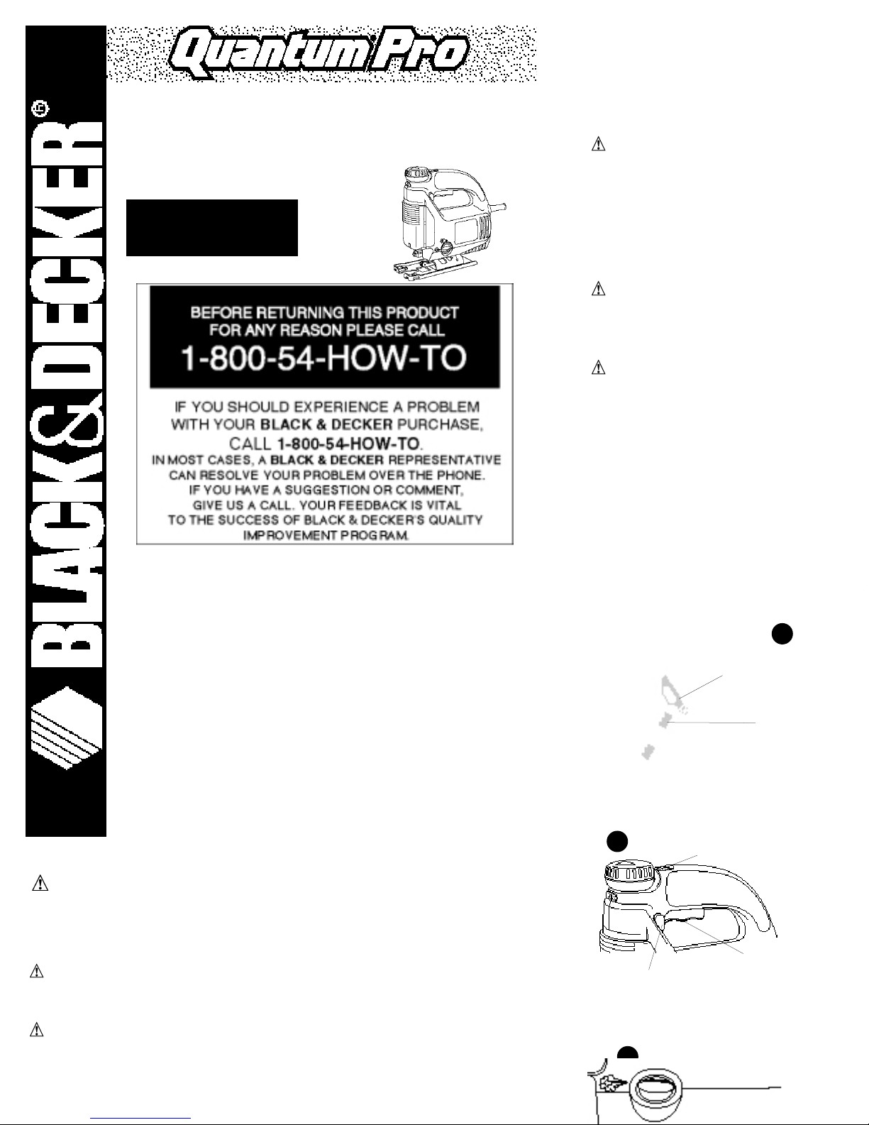
INSTRUCTION MANUAL
VARIABLE SPEED SCROLLER JIG SAW
KEY INFORMATION YOU SHOULD KNOW:
• The saw cannot be turned on by only rotating the speed wheel–the
trigger must be depressed.
•Securely tighten roller support guide before use.
• Pull up scroller knob completely before rotating.
VEA EL ESPAÑOL EN LA CONTRAPORTADA.
SAVE THIS MANUAL FOR FUTURE REFERERENCE.
INSTRUCTIVO DE OPERACIÓN, CENTROS DE SERVICIO Y PÓLIZA DE
GARANTÍA. ADVERTENCIA: LÉASE ESTE INSTRUCTIVO ANTES DE USAR EL
PRODUCTO.
OUICK CLAMP™ BLADE CLAMP LEVER
LEVIER DU SERRE-LAME QUICK CLAMP
mc
PALANCA DEL PORTA SEGUETAS QUICK CLAMP™
BLADE
LAME
SEGUETA
1
3
SPEED WHEEL
RÉGULATEUR DE VITESSE
PERILLA DE CONTROL DE VELOCIDAD
TRIGGER SWITCH
INTERRUPTEUR À DÉTENTE
GATILLO INTERRUPTOR
LOCK ON BUTTON
BOUTON DE VERROUILLAGE
EN MODE DE FONCTIONNEMENT
BOTON DE ENCENDIDO PERMANENTE
5
ANGLE ADJUSTMENT MARKINGS
MARQUES DE RÉGLAGE DE L’ANGLE
MARCAS DE AJUSTE ANGULAR
Page 2

ASSEMBLY/ADJUSTMENT SET-UP
nstalling Blades
BEFORE INSTALLING BLADES, TURN OFF AND UNPLUG TOOL.
Y our jig saw uses the Quick Clamp™ blade changing system. To install a blade, lift the Quick Clamp™
lever (Figure 1). Insert the saw blade shank fully into the blade clamp. Release the lever and the blade will
be clamped securely in place. The back of the blade should be almost touching the roller support guide.
Ensure the blade teeth are facing forward.
Roller Support Guide
The roller support guide on your jig saw improves its performance when cutting tough materials by adding
support to the blade. Adjust the support roller by loosening the screw on the bottom of the shoe, as shown
in Figure 2 and moving the roller so that it almost, but not quite, touches the blade. Tighten the screw
securely to lock the roller in place.
Switch
Y our jig saw has a variable speed switch. To turn the saw on, squeeze the trigger switch, as shown in
Figure 3. Hold the trigger switch in as you rotate the speed wheel to the desired setting.
The selected speed will be maintained, under reasonable loading, as you cut.
NOTE: The numbers on the speed wheel are for reference only. They do not represent any particular speed.
T o turn the tool off, release the trigger switch.
The tool can be locked on for continuous operation at any speed by squeezing and holding the trigger
switch while you depress the lock-on button. With the lock-on button depressed, release the trigger switch
and the tool will continue to run. T o release from lock position, squeeze and release the trigger switch once.
Although your saw will maintain speed and power , don’ t overload it as this could damage the motor. Use
your saw only for its intended purpose. If it should overheat, turn it on at its highest speed and run it
without a load until it cools down.
SPEED TEETH
MATERIAL SETTING PER INCH
Soft Wood 6-MAX 7
Hard Wood 5-MAX 7
Plastic 4-6 14
Aluminum 3-6 14
Steel 2-4 24
Tile 1-3 24
Glass 1-3 32
Leather 4-6 0 (Knife Edge)
Rubber 4-6 0 (Knife Edge)
NOTE: Speed setting 1 is the slowest and MAX is the fastest.
Bevel Adjustment
TURN OFF AND UNPLUG TOOL.
Raise or remove the dust shield before bevel cutting.
T o adjust the bevel angle, loosen the rear screw on the bottom of the shoe, as shown in Figure 4. Pull the
show backward slightly and set the shoe to the desired angle. Angle adjustment is indicated on the raised
portion of either side of the shoe (Figure 5). It is also possible to push the shoe forward to set fixed positions
of 0°, 15°, 30° or 45°. A protractor is recommended when very accurate cuts are required.
T o reset the shoe for a square cut, loosen the rear screw and move the shoe until it is approximately 90°to
the blade. While applying slight forward pressure to the shoe, retighten the rear screw.
General Cutting
Be sure board is firmly secured. Hold jig saw by the handle and operate switch to turn the unit on. Don’t
attempt to turn on the unit when blade is against material to be cut. This could stall the motor . Place front of
shoe on material to be cut and hold jig saw shoe down firmly against the work surface while cutting. Don’t
force the tool; let the blade cut at its own speed. Whenever possible, clamp or support work close to the
line of cut; when the cut is completed, shut off power and lay the saw aside before loosening the work.
Scrolling
Y our jig saw is equipped with a manual scrolling feature which permits the saw blade to completely rotate
without rotating the entire saw.
NOTE: Before scrolling, retract the roller support guide and ensure the shoe is in the forward position.
Push the scroller release button, as shown in Figure 6. The scrolling knob will pop out of the tool housing.
PULL THE KNOB UP. Using one hand to guide the jig saw, turn the scroller knob to guide the blade along
the line of the cut. The blade will turn 360°.
The angle of the blade can be locked into one of four positions: 0°, 90°, 180° or 270°. T o lock the blade
in any of the four positions, push the scroller release button, and push the scrolling knob down. When the
button is released, the blade is locked into position.
T o reset, push the scroller release button. To return to straight-line (non-scrolling) cutting, press the scroller
release button and push the knob down. Readjust the roller support guide so it is almost touching the back
of the blade.
Dust Shield
Y our jig saw is equipped with a dust shield to aid with dust removal. Place the shield in the down position
when extracting dust.
NOTE: T o clean dust shield, first unplug saw from power supply. Use only a dry rag or rag dampened with
plain water to wipe clean. When bevel cutting always keep the dust shield in the UP position.
Dust Extraction/V acuum Attachment
Y our jig saw is equipped with a dust extraction system which greatly reduces clean up time. To extract dust:
Insert the end of the supplied vacuum adapter into the dust extraction opening at the rear of the saw.
Attach a standard vacuum cleaner hose.
T urn the dust blower switch (Figure 7) to the right. Lower the dust shield.
T urn on the vacuum. Turn on the jig saw and begin cutting.
Accessories
Recommended accessories for use with your tool are availa
center . If you need assistance regarding accessories, please
WARNING: The use of any accessory not recommen
SERVICE INFORMA TION
Black & Decker offers a full network of company-owned an
America. All Black & Decker Service Centers are staffed w
efficient and reliable power tool service.
Whether you need technical advice, repair , or genuine fac
Decker location nearest you. T o find your local service loca
“T ools—Electric” or call: 1-800-54-HOW TO.
FULL TWO-YEAR HOME USE W ARRANTY
Black & Decker (U.S.) Inc. warrants this product for two ye
workmanship. The defective product will be replaced or re
The first, which will result in exchanges only, is to return the
purchased (provided that the store is a participating retaile
period of the retailer’ s policy for exchanges (usually 30 to 9
be required. Please check with the retailer for their specific
the time set for exchanges.
The second option is to take or send the product (prepaid)
Service Center for repair or replacement at our option. Pro
owned and authorized Service Centers are listed under “To
directory.
This warranty does not apply to accessories. This warranty
have other rights which vary from state to state. Should you
your nearest Black & Decker Service Center.
Imported by
Black & Decker (U.S.) Inc.,
701 E. Joppa Rd.
Towson, MD 21286 U.S.A.
Q425
GUIDE D’UTI
RENSEIGNEMENTS
•On ne peut pas mettre la scie en m
régulateur de vitesse seulement; il fa
•Bien serrer le rouleau porteur avant
•Soulever complètement le bouton d
tourner.
FRANÇ
AVANT DE RETOURNER LE P
LA RAISON, PRIÉRE D
1 800 544
Page 3

supérieur et sûr . Suivre les directives concernant la lubrification et le remplacement des accessoires.
Inspecter régulièrement le cordon de l’outil et le faire réparer au besoin à un atelier d’entretien autorisé.
Inspecter régulièrement les cordons de rallonge et les remplacer lorsqu’ils sont endommagés. S’assurer
que les poignées sont toujours propres, sèches et libres de toute tache d’huile ou de graisse.
DÉBRANCHER LES OUTILS. Débrancher l’outil lorsqu’on ne s’en sert pas, qu’on doit le déplacer d’un
endroit à un autre et qu’on doit le réparer ou en changer un accessoire (comme une lame, un foret ou un
couteau).
ENLEVER LES CLÉS DE RÉGLAGE. Prendre l’habitude de vérifier si les clés de réglage ont été retirées avant
de faire démarrer l’outil.
ÉVITER LES DÉMARRAGES ACCIDENTELS. Ne pas laisser le doigt sur l’interrupteur lorsqu’on transporte
l’outil. S’assurer que l’interrupteur est à la position hors circuit lorsqu’on branche l’outil.
CORDONS DE RALLONGE. S’assurer que le cordon de rallonge est en bon état. Lorsqu’on se sert d’un
cordon de rallonge, s’assurer qu’il est de calibre approprié pour la tension nécessaire au fonctionnement
de l’outil. L’utilisation d’un cordon de calibre inférieur occasionne une baisse de tension entraînant
une perte de puissance et la surchauffe. Le tableau suivant indique le calibre approprié selon la longueur
du cordon et les mentions de la plaque signalétique de l’outil. En cas de doute, utiliser un cordon de
calibre supérieur . Le chiffre indiquant le calibre est inversement proportionnel au calibre du cordon.
CORDONS DE RALLONGE PRÉVUS POUR L’EXTÉRIEUR. Lorsque l’outil est utilisé àl’extérieur, ne se servir
que d’un cordon de rallonge conçu pour l’extérieur et portant la mention appropriée.
DEMEURER VIGILANT . Travailler avec vigilance et faire preuve de bon sens. Ne pas se servir de l’outil
lorsqu’on est fatigué.
VÉRIFIER LES PIÈCES ENDOMMAGÉES. Avant de continuer à utiliser l’outil, il faut vérifier si le protecteur
ou toute autre pièce endommagée remplit bien la fonction pour laquelle il a été prévu. Vérifier
l’alignement et les attaches des pièces mobiles, le degré d’usure des pièces et leur montage, ainsi que tout
autre facteur susceptible de nuire au bon fonctionnement de l’outil. Faire réparer ou remplacer tout
protecteur ou toute autre pièce endommagée dans un centre de service autorisé. Ne jamais se servir d’un
outil dont l’interrupteur est défectueux.
ACCESSOIRES. L’utilisation d’accessoires non recommandé pour l’outil peut être dangereuse. Note:
Consulter la rubrique relative aux accessoires du présent guide pour obtenir de plus amples
renseignements à ce sujet.
MESURES DE SÉCURITÉ : DOUBLE ISOLATION
Les outils à double isolation comportent deux couches distinctes d’isolant électrique ou une double
épaisseur d’isolant qui protègent l’utilisateur contre les risques de blessures provenant du système
électrique de l’outil. Ce système de double isolation élimine le besoin de mettre les outils à la terre. En effet,
l’outil est muni d’une fiche à deux broches, ce qui permet d’utiliser une rallonge ordinaire sans avoir à se
soucier d’assurer la mise à la terre.
NOTE: La double isolation ne dispense pas des mesures de sécurité normales lors de l’utilisation de l’outil.
Elle vise à procurer une protection supplémentaire contre les blessures que peut entraîner une défectuosité
de l’isolant électrique à l’intérieur de l’outil.
MISE EN GARDE : LORS DE L’ENTRETIEN, N’UTILISER QUE DES PIÈCES DE RECHANGE IDENTIQUES.
Réparer ou remplacer les cordons endommagés.
MESURES DE SÉCURITÉ : FICHE POLARISÉE
Afin de réduire les risques de secousses électriques, l’outil est muni d’une fiche polarisée (une lame plus
large que l’autre). Ce genre de fiche n’entre que d’une façon dans une prise polarisée. Lorsqu’on ne peut
insérer la fiche à fond dans la prise, il faut tenter de le faire après avoir inversé les lames de côté. Si la
fiche n’entre toujours pas dans la prise, il faut communiquer avec un électricien certifié. Il ne faut en aucun
cas modifier la fiche.
MESURES DE SÉCURITÉ : SCIES SAUTEUSES
MISE EN GARDE : Lorsqu’on scie dans les murs, les planchers ou tout autre endroit où peuvent se trouver
des fils sous tension, NE PAS TOUCHER À TOUT COMPOSANT MÉTALLIQUE DE L ’OUTIL. Ne le saisir que
par ses surfaces de prise en plastique afin de se protéger des secousses électriques que provoqueraient le
contact de la lame avec un fil sous tension.
ÉLOIGNER LES MAINS de la zone de coupe. Ne jamais placer les mains sous le matériau lorsque la scie
fonctionne.
S’ASSURER QUE LA LAME EST BIEN AFFÛTÉE. Les lames émoussées peuvent faire dévier la scie ou la faire
caler sous pression.
MISE EN GARDE : Certaines essences de bois renferment des agents de conservation (comme de
l’arséniate de cuivre et de chrome) qui peuvent être toxiques. Lorsqu’on doit couper de tels matériaux,
prendre des mesures supplémentaires afin d’éviter d’inhaler les vapeurs toxiques et de minimiser les
contacts avec la peau.
CONSERVER CES MESURES À TITRE DE RÉFÉRENCE.
Moteur
Veiller à ce que la tension d’alimentation soit conforme aux exigences de la plaque signalétique de l’outil.
La mention «120 volts c.a. seulement» signifie que l’outil fonctionne sur du courant alternatif et jamais sur
du courant continu.
Une baisse de tension de plus de 10 p. 100 entraîne la baisse de puissance et la surchauffe de l’outil. Tous
RÉGLAGE DE
MATÉRIAU LA VITESSE
Résineux 6-MAX
Feuillus 5-MAX
Plastique 4-6
Aluminium 3-6
Acier 2-4
Céramique 1-3
Verre 1-3
Cuir 4-6
Caoutchouc 4-6
NOTE : Le chiffre 1 correspond à la vit
maximale.
Réglage pour coupes en biseau
METTRE L’OUTIL HORS TENSION ET LE DÉBRANCHER.
Pour régler l’angle de coupe, desserrer la vis arrière du de
Tirer le patin légèrement vers l’arrière et le régler à l’angle
partie en relief de chaque côté du patin (fig. 5). On peut ég
le régler à des positions prédéterminées de 0°, 15°, 30° ou
d’angles pour effectuer des coupes très précises.
Pour remettre le patin en position de coupe à angle droit, d
jusqu’à ce qu’il soit à environ 90° de la lame. T out en exer
resserrer la vis arrière.
Coupes de nature générale
S’assurer que le matériau à scier est bien retenu. Saisir la s
l’interrupteur pour mettre la scie en marche. Ne jamais me
contre le matériau à découper , car cela peut faire caler le
à scier et appuyer fermement le patin contre la surface de
l’outil; laisser la lame travailler d’elle-même. Il est toujours
plus près possible de la ligne de coupe. Lorsqu’on a termin
tension et le déposer ailleurs avant de dégager la pièce.
Chantournage
La scie sauteuse comporte une fonction de chantournage m
complet sur elle-même sans avoir à faire tourner la scie.
NOTE : Avant de chantourner, rétracter le rouleau porteur
Pousser le bouton de dégagement du mode de chantourna
chantournage sort de l’outil. Le soulever. D’une main, guid
afin de guider la lame le long de la ligne de coupe. La lam
On peut verrouiller l’angle de la lame dans une des quatre
Pour verrouiller la lame, pousser le bouton de dégagemen
bouton de chantournage. La lame est verrouillée en place
Pour régler de nouveau, enfoncer le bouton de dégageme
ligne droite, enfoncer le bouton de dégagement du mode d
de nouveau le rouleau porteur de sorte qu’il frôle l’arrière
Écran anticopeaux
La scie sauteuse comporte un écran anticopeaux facilitant
dépoussiérage.
NOTE : Il faut d’abord débrancher l’outil avant de nettoyer
chiffon sec ou trempé dans de l’eau propre pour l’essuyer.
en biseau.
Dépoussiérage - Adaptateur pour aspirate
La scie sauteuse est dotée d’un système de dépoussiérage
servir, faire ce qui suit.
• Insérer l’extrémité de l’adaptateur fourni dans l’orifice d
un boyau d’aspirateur standard.
• Faire tourner l’interrupteur du ventilateur (fig. 7) vers la
• Mettre l’aspirateur en marche. Mettre la scie sauteuse e
Ventilateur de la ligne de coupe
La scie sauteuse comporte un ventilateur pour la ligne de c
zone de coupe. Pour s’en servir, faire tourner l’interrupteur
Coupe des métaux et du plastique
Pour couper les tôles minces, il vaut mieux fixer une pièce d
effectue ainsi des coupes nettes en évitant les risques de vib
lame délicate pour scier les métaux ferreux et une lame gro
La coupe des tôles minces est plus longue que le sciage d’u
donc éviter d’accélérer le processus en forçant l’outil. Dépo
de préférence) sur la ligne de coupe et consulter le tableau
appropriée.
Scier les métaux, le plastique et les agglomérés à basse vit
finie de la pièce vers le bas, se servir d’une lame délicate à
Coupe en retrait
• Mesurer la surface à scier et bien la tracer au crayon. I
le bord avant du patin repose fermement contre la surfa
• Mettre l’outil en marche et le laisser atteindre la vitesse
• Bien saisir la poignée et rabaisser la scie jusqu’à ce que
s’assurer que la lame s’enfonce le plus profondément p
Calibre minimal des cordons de rallonge
Tension Longueur totale du cordon en pieds
120 V De 0 à 25 De 26 à 50 De 51 à 100 De 101 à 150
240 V De 0 à 50 De 51à 100 De 101 à 200 De 201 à 300
Intensité (A)
Au Au Calibre moyen de fil
moins plus
0-6 18 16 16 14
6 - 10 18 16 14 12
10 - 12 16 16 14 12
12 - 16 14 12 Non recommandé
Page 4

NOTE : La présente garantie et les dispositions précitées peuvent ne pas être valides dans certaines
provinces. La liste complète des centres de service se trouve dans l’emballage.
Renseignements relatifs au service
Black & Decker exploite un réseau complet de centres de service et d’ateliers d’entretien autorisés par toute
l’Amérique du Nord. Le personnel de tous les centres de service Black & Decker a reçu la formation voulue
pour assurer l’entretien efficace et fiable des outils électriques.
Pour obtenir des renseignements d’ordre technique, des conseils relatifs aux réparations ou des pièces de
rechange d’origine, communiquer avec le centre de service Black & Decker de la région.
On peut trouver l’adresse du centre de service de la région dans l’annuaire des Pages Jaunes à la rubrique
«Outils électriques» ou en composant le numéro suivant : 1 800 544-6986.
necesita. Una extensión con calibre menor al necesario ca
resultando en pérdida de potencia y sobrecalentamiento.
para usarse, de acuerdo con la longitud de la extensión y
tiene dudas, utilice el calibre siguiente. Mientras menor se
capacidad del cable.
• CORDONES DE EXTENSION PARA INTEMPERIE.Cuando
únicamente extensiones destinadas para este uso y marca
• ESTE ALERT A.Concéntrese en lo que hace. Utilice el sentid
cansado o discapacitado de alguna manera.
• REVISE LAS PAR TES DAÑADAS.Antes de seguir usando l
partes para determinar realizarán su función adecuadam
la manera en que están sujetas, que no haya piezas o sop
que puedan afectar la operación. Una guarda u otra piez
reemplazada en un centro de servicio autorizado. No use
apaga.
• SERVICIO Y REPARACIONES.Las reparaciones, el manten
este manual deben ser realizados por los centros de servic
de servicio calificadas, que siempre utilicen refacciones id
• EMPLEO DE ACCESORIOS Y DISPOSITIVOS. El uso de cua
para emplearse con esta herramienta puede ser peligroso
accesorios de este manual para obtener más detalles.
ADVERTENCIAS E INSTRUCCIONES DE
AISLAMIENTO
Las herramientas con doble aislamiento están construidas
eléctrico o una capa de espesor doble entre usted y el siste
herramientas con doble aislamiento no necesitan conectar
equipada con una clavija de dos patas que le permite utiliz
conexión a tierra.
El doble aislamiento no reemplaza las precauciones norma
herramienta. El sistema de aislamiento le proporciona pro
de posibles fallas en el aislamiento eléctrico de la herramie
PAR TES DE REPUESTO:Solamente emplee refacciones idén
reemplace los cordones eléctricos dañados.
ADVERTENCIAS E INSTRUCCIONES DE
POLARIZADAS
Las clavijas polarizadas (con una pata más ancha que la o
riesgo de choque eléctrico. Estas clavijas solamente se ajus
la clavija no se ajusta completamente a la toma de corrien
con un electricista calificado para que le instale la toma de
la clavija en ninguna manera.
ADVERTENCIAS E INSTRUCCIONES DE
CALADORAS
•PRECAUCION: Cuando corte en muros, pisos o dondequie
¡NO TOQUE NINGUNA PAR TE METALICA DE LA HERRA
las superficies aislantes (empuñaduras) para evitar el choq
• CONSERVE LAS MANOS ALEJADAS del área de corte. N
ninguna razón.
• CONSERVE AFILADAS LAS SEGUETAS.Las seguetas mella
bajo presión.
• PRECAUCION: Algunos tipos de madera contienen conse
(CCA) que pueden ser tóxicos. Cuando corte estos materia
y minimizar el contacto de estas sustancias con la piel.
CONSERVE ESTAS INSTRUCCIONES
Motor
Asegúrese que su alimentación de corriente concuerde co
120 V~ significa que su sierra funciona con corriente dom
para corriente alterna con corriente continua. Disminucion
pérdida de potencia y pueden producir sobrecalentamient
T odas las herramientas se prueban en la fábrica; si esta he
de corriente.
ENSAMBLAJE/AJUSTES INICIALES
Instalación de las seguetas
ANTES DE INSTALAR SEGUETAS, AP AGUE Y DESCONEC
Imported by / Importé par
Black & Decker Canada Inc.
100 Central Ave.
Brockville (Ontario) K6V 5W6
Voir la rubrique “Outils électriques”
des Pages Jaunes
pour le service et les ventes.
ESPAÑOL
MANUAL DE INSTRUCCIONES
Q425
ANTES DE DEVOLVER ESTE PRODUCTO POR CUALQUIER
RAZON POR FAVOR LLAME
326-7100
INFORMACION QUE DEBE SABER
•La sierra no puede encenderse solamente con girar la perilla de control de velocidad, debe
oprimirse el gatillo.
•Apriete con firmeza la guía de soporte de rodillos antes de usar la herramienta.
•Tire de la perilla de calado hacia arriba completamente antes de girarla.
CONSERVE ESTE MANUAL PARA REFERENCIAS FUTURAS
STRUCTIVO DE OPERACIÓN, CENTROS DE SERVICIO Y PÓLIZA DE GARANTÍA.
DVERTENCIA: LÉASE ESTE INSTRUCTIVO ANTES DE USAR EL PRODUCTO. SI TIENE
UDAS, POR FA VOR LLAME. 326-7100
ADVERTENCIA: ADVERTENCIAS E INSTRUCCIONES IMPORTANTES DE
SEGURIDAD
ARA REDUCIR EL RIESGO DE LESIONES:
Antes de cualquier uso, asegúrese que cualquier persona que vaya a utilizar esta herramienta lea y
comprenda todas las instrucciones de seguridad y la información contenida en este manual.
Conserve estas instrucciones y repáselas con frecuencia antes de usar la herramienta e instruir a otras
personas.
ADVERTENCIA: Siempre que utilice herramientas eléctricas debe seguir ciertas precauciones
básicas de seguridad, a fin de reducir los riesgos de incendio, choque eléctrico y
lesiones personales, entre las que se encuentran las siguientes.
LEA TODAS LAS INSTRUCCIONES
ADVERTENCIAS E INSTRUCCIONES GENERALES DE SEGURIDAD PARA
TODAS LAS HERRAMIENTAS.
CONSERVE LIMPIA EL AREA DE TRABAJO. Las áreas y los bancos con objetos acumulados en desorden
propician los accidentes.
OTORGUE PRIORIDAD AL AMBIENTE DE TRABAJO. No exponga las herramientas eléctricas a la lluvia ni
Calibre mínimo para
Volts Longitu
120V 0-7.62 7.6
240V 0-15.24 15.2
AMPERAJE
Más No más
de de
0-6 18
6 - 10 18
10 - 12 16
12 - 16 14
Page 5

Ajuste de bisel
APAGUE Y DESCONECTE LA HERRAMIENTA
Para ajustar el ángulo de biselado, afloje el tornillo trasero de la parte inferior de la zapata, como se
observa en la figura 4. Tire de la zapata ligeramente hacia atrás y colóquela en el ángulo que desee. El
ajuste angular se indica en la porción elevada de cada lado de la zapata (figura 5). Es posible empujar la
zapata hacia adelante para colocarla en posiciones preestablecidas de 0°, 15°, 30° o 45°. Se
recomienda un transportador cundo requiera cortar con mucha precisión.
Para ajustar la zapata para cortes a escuadra, afloje el tornillo trasero y gire la zapata hasta quedar
aproximadamente a 90° con respecto a la segueta. Aplique un poco de presión a la zapata hacia
adelante al mismo tiempo que aprieta el tornillo trasero.
Corte general
Asegúrese que la tabla esté firme. Sujete la sierra caladora por el mango y oprima el gatillo interruptor
para encenderla. No intente encender la unidad cuando la segueta esté apoyada sobre la superficie de
trabajo, esto podría atascar el motor . Coloque el frente de la zapata sobre el material que vaya a cortar y
presione la zapata con firmeza contra la superficie de trabajo durante el corte. No fuerce la herramienta;
permita que la segueta corte a su propia velocidad. Siempre que sea posible, prense o apoye la pieza de
trabajo en un sitio cercano a la línea de corte; cuando haya completado el corte, apague la sierra y
colóquela a un lado antes de soltar la pieza de trabajo.
Calado
Su sierra caladora está equipada con un dispositivo para calado manual que permite que la segueta gire
completamente sin girar la sierra completa.
NOTA:antes de calar, retraiga la guía de soporte de rodillo y asegúrese que la zapata esté en la posición
adelantada.
Empuje el botón de liberación de calado, como se observa en la figura 6. La perilla de calado saltará de
la carcaza de la herramienta. Tire de la perilla hacia arriba. Guíe la sierra con una mano y gire la perilla
de calado para guiar la segueta a lo largo de la línea de corte. La segueta podrá girar 360°.
El ángulo de la segueta se podrá asegurar en una de cuatro posiciones: 0°, 90°, 180° o 270°. Para
asegurar la segueta en cualquiera de las cuatro posiciones, empuje el botón de liberación de calado y
empuje la perilla de calado hacia abajo. Al soltar el botón de liberación, la segueta queda asegurada en
posición.
Para ajustar la segueta a 0° de nuevo para corte recto, oprima el botón de liberación de calado y empuje
la perilla hacia abajo. Reajuste la guía de soporte de rodillo para que casi haga contacto con la parte
trasera de la segueta.
Protector contra polvo
Su sierra caladora está equipada con una cubierta para ayudar a eliminar el polvo. Coloque la cubierta
en la posición baja cuando haga extracción de polvo.
NOTA:Para limpiar la cubierta contra polvo, desconecte primero la sierra de la alimentación de corriente.
utilice únicamente un trapo seco o un trapo humedecido con agua limpia para frotar . Cuando corte a
bisel, conserve siempre la cubierta en la posición ALTA.
Extracción de polvo/Dispositivo para aspiradora
Su sierra caladora está equipada con un sistema de extracción de polvo que reduce en gran medida el
tiempo de limpieza. Para extraer el polvo:
Inserte el extremo del adaptador para aspiradora en la abertura de extracción de polvo en la parte
posterior de la sierra. Instale una manguera de aspiradora estándar.
Gire el interruptor del soplador de polvo (figura 7) hacia la derecha.
Encienda la aspiradora. Encienda la sierra caladora y comience a cortar.
Soplador en la línea de corte
Su sierra caladora está equipada con un soplador en la línea de corte para conservar libre de polvo el
área de corte mientras usted trabaja. Para utilizar el soplador, gire el interruptor del soplador (figura 7)
hacia la izquierda.
Corte de metales y plásticos
Para cortar láminas metálicas delgadas, es mejor prensar madera o madera contraplacada a la parte
inferior de la lámina; esto asegurará un corte limpio sin el riesgo de que las vibraciones desgarren el
metal. Utilice una segueta de dientes finos para metales ferrosos (aquellos con contenido de hierro) y una
segueta con dientes más grandes para los metales no ferrosos (aquellos que no contienen hierro).
Cortar metal delgado llevará más tiempo que cortar madera relativamente gruesa, de manera que no
intente acelerar el proceso forzando la sierra. Distribuya una película delgada de lubricante para corte a
lo largo de la línea de corte (cualquier aceite ligero) y consulte la tabla de seguetas en este manual para
seleccionar la segueta adecuada para su aplicación.
Utilice velocidades bajas para cortar metales, plásticos y mosaico. Cuando corte laminados plásticos,
coloque la cara con el acabado hacia abajo y utilice una segueta con dientes cóncavos.
Corte de bolsillo
Mida la superficie por cortar y márquela claramente con lápiz. Incline a continuación la sierra hacia
adelante hasta que la parte frontal de la zapata asiente con firmeza contra la superficie de trabajo
(figura 8).
Encienda la sierra y espere a que llegue a la máxima velocidad.
Sujete firmemente la empuñadura y haga descender el borde posterior de la herramienta hasta que
la segueta corte el material con suavidad. Asegúrese que la segueta alcance su profundidad máxima
antes de empezar el corte. Para los cortes de bolsillo el selector debe conservarse en la posición de
corte recto.
Cortes al hilo y circulares
Los cortes al hilo y en círculo sin líneas trazadas con lápiz se efectúan con facilidad con el accesorio de
corte al hilo y guía para cortes circulares (disponible con cargo extra).
PARA REPARACION Y SERVICIO DE SUS HER
DIRIGIRSE AL CENTRO DE SER
CULIACAN
Av . Nicolas Bravo #1063 Sur (91 6
GAUDALAJARA
Av . La Paz #1779 (91 3
MEXICO
Eje Lázaro Cárdenas No. 18 Local D, Col. Obrera 588-
MERIDA
Calle 63 #459-A (91 9
MONTERREY
Av . Francisco I. Madero Pte. 1820-A (91 8
PUEBLA
17 Norte #205 (91 2
QUERETARO
Av . Madero 139 Pte. (91 4
SAN LOUIS POTOSI
Pedro Moreno #100 Centro (91 4
TORREON
Blvd. Independencia, 96 pte. (91 1
VERACRUZ
Prolongación Diaz Miron #4280 (91 2
VILLAHERMOSA
Constitucion 516-A (91 9
PARAOTRAS LOCALIDADES
INFORMACIÓN DE SERVICIO
Black & Decker ofrece una red completa de centros de serv
a través de toda Norteamérica. Todos los centros de servic
capacitado para proporcionar el servicio a herramientas
Siempre que necesite consejo técnico, reparaciones o part
centro Black & Decker más cercano a usted.
Para encontrar su centro de servicio local, consulte la secc
llame al: 326-7100.
POLIZA DE GARANTIA
IDENTIFICACION DEL PRODUCTO:
Sello firma del Distribuidor .
Nombre del producto:_____________ Mod/Cat.: ____
Marca: _________________________ Núm. de serie:_
(Datos para ser llenados por el distribuidor)
Fecha de compra y/o entrega del producto: ____________
Nombre y domicilio del distribuidor donde se adquirió el p
_________________________________________________
Este producto esta garantizado por dos años a partir de la
su funcionamento, así como en materiales y mano de obra
garantía incluye la reparación o reposición del producto y
cliente, incluyendo mano de obra, así como los gastos de t
derivados del cumplimiento de este certificado.
Para hacer efectiva esta garantía deberá presentar su her
sellada por el establecimiento comercial donde se adquirió
factura de compra.
EXCEPCIONES.
Esta garantía no será válida en los siguientes casos:
• Cuando el producto se hubiese utilizado en condicione
• Cuando el producto no hubiese sido operado de acue
paña;
• Cuando el producto hubiese sido alterado o reparado
de este certificado.
Anexo encontrará una relación de sucursales de servicio d
franquiciados en la República Mexicana, donde podrá ha
refaciones y accesorios originales.
T odas las herramientas Black & Decker son de la mejor cal
IMPOR
BOSQUE
Para servicio y ventas consulte
“HERRAMIENTAS ELECTRICAS”
en la sección amarilla.
ESPECIFICACIO
Tensión de alimentación:
Potencia nominal:
Frecuencia de operación:
Consumo de corriente:
Page 6

 Loading...