

Page 1
General Safety Rules
WARNING: Read and understand all instructions. Failure to follow all instructions listed below
may result in electric shock, fire and/or serious personal injury.
SAVE THESE INSTRUCTIONS
WORK AREA
Keep your work area clean and well lit. Cluttered benches and dark areas invite accidents.
Do not operate power tools in explosive atmospheres, such as in the presence of flammable liquids,
gases, or dust. Power tools create sparks which may ignite the dust or fumes.
Keep bystanders, children, and visitors away while operating a power tool. Distractions can cause you
to lose control.
LECTRICAL SAFETY
Double insulated tools are equipped with a polarized plug (one blade is wider than the other .) This
plug will fit in a polarized outlet only one way. If the plug does not fit fully in the outlet, reverse the
plug. If it still does not fit, contact a qualified electrician to install a polarized outlet. Do not change the
plug in any way. Double insulation eliminates the need for the three wire grounded power cord and
TOOL USE AND CARE
• Use clamps or other practical way to secure and suppo
the work by hand or against your body is unstable and m
• Do not force tool. Use the correct tool for your applicatio
safer at the rate for which it is designed.
• Do not use tool if switch does not turn it on or off. Any to
dangerous and must be repaired.
• Disconnect the plug from the power source before maki
storing the tool. Such preventative safety measures reduc
• Store idle tools out of reach of children and other untrai
of untrained users.
• Maintain tools with care. Keep cutting tools sharp and c
cutting edges are less likely to bind and are easier to con
• Check for misalignment or binding of moving parts, bre
may affect the tools operation. If damaged, have the to
caused by poorly maintained tools.
• Use only accessories that are recommended by the man
be suitable for one tool, may become hazardous when us
SERVICE
• T ool service must be performed only by qualified repair
by unqualified personnel could result in a risk of injury.
• When servicing a tool, use only identical replacement p
section of this manual. Use of unauthorized parts or failu
create a risk of electric shock or injury.
SPECIFIC SAFETY RULES
• Hold tool by insulated gripping surfaces when performin
contact hidden wiring or its own cord. Contact with a "liv
tool "live" and shock the operator .
The label on your tool may include the following symb
V ..........................volts
Hz ........................hertz
min ......................minutes
....................direct current
........................
Class II Construction
........................safety alert symbol
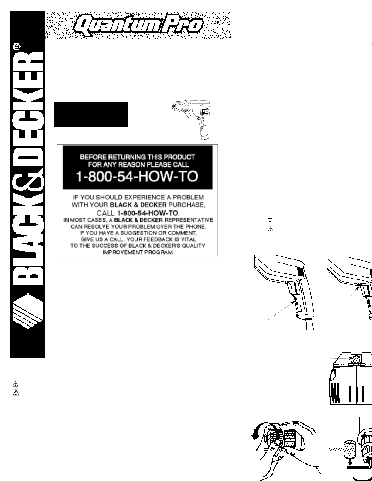
Q210
INSTRUCTION MANUAL
3/8" (10MM) 5.0 AMP
KEYLESS CHUCK DRILL
INFORMATION YOU SHOULD KNOW
•Hand tighten keyless chuck firmly after each bit change.
VEA EL ESPAÑOL EN LA CONTRAPORTADA.
SAVE THIS MANUAL FOR FUTURE REFERERENCE.
INSTRUCTIVO DE OPERACIÓN, CENTROS DE SERVICIO Y PÓLIZA DE
GARANTÍA. ADVERTENCIA: LÉASE ESTE INSTRUCTIVO ANTES DE USAR EL
PRODUCTO.
AT. NO. Q210 FORM NO. 386868 (JAN98 CD-1) COPYRIGHT 1998 PRINTED IN USA
Fig. 3B
BUBBLE
BULLE
Fig. 1
Fig. 2
REVERSING LEVER
INVERSEUR DE MARCHE
"A"
Page 2

9. With variable speed drills there is no need to center punch the point to be drilled. Use a slow speed
o start the hole and accelerate by squeezing the trigger harder when the hole is deep enough to drill
without the bit skipping out.
DRILLING IN MET AL
se a cutting lubricant when drilling metals. The exceptions are cast iron and brass which should be drilled dry. The
utting lubricants that work best are sulphurized cutting oil or lard oil; bacon-grease will also serve the purpose.
OTE: Large (5/16" to 3/8") (7.9mm to 9.5mm) holes in steel can be made easier if a pilot hole (5/32" to 3/16")
3.9mm to 4.8mm) is drilled first.
DRILLING IN WOOD
oles in wood can be made with the same twist drills used for metal. These bits may overheat unless pulled out
equently to clear chips from the flutes. For larger holes, use power drill wood bits. Work that is apt to splinter
hould be backed up with a block of wood.
DRILLING IN MASONRY
se carbide-tipped masonry bits at low speeds. Keep even force on the drill but not so much that you crack the
rittle materials. A smooth, even flow of dust indicates the proper drilling rate.
BUILT-IN 2-WAY LEVEL
our drill is equipped with a 2-way bubble level that assists you in drilling level holes. For horizontal drilling, tilt the
rill up or down as required so the bubble floats in the center of the parallel lines drawn on the glass. When the
ubble is centered between the lines, as shown in Figure 3A, the drill is level. For vertical drilling, align the drill so
at the bubble in the level floats in the center of the bull’s-eye, as shown in Figure 3B. To assure accuracy, first place
level on your workpiece and position it so that it is level. Then, when the drill reads level, the two will be aligned.
Any bubble level can only indicate level relative to the earth.)
OTE: The level is filled with mineral oil that may cause minor skin or eye irritation when contacted. If the level
reaks and this fluid gets on your skin, rinse thoroughly with water. If any liquid gets in your eyes, rinse thoroughly
ith water and call a physician immediately.
KEYLESS CHUCK
our tool features a keyless chuck for greater convenience. To insert a drill bit or other accessory, follow the steps
sted below.
1. TURN OFF AND UNPLUG. Make sure that the lock-on button is released.
2. Grasp the rear half of the chuck with one hand and use your other hand to rotate the front half in the direction
marked RELEASE on the nose of the chuck, as shown in Figure 4. Rotate far enough so that the chuck opens
ufficiently to accept the desired accessory.
3. Insert the bit or other accessory about 3/4" (19mm) into the chuck and tighten securely by holding the rear
alf of the chuck and rotating the front portion in the GRIP direction. To release the accessory, repeat step 2 listed
bove.
WARNING: Do not attempt to tighten drill bits (or any other accessory) by gripping the front part of the chuck
nd turning the tool on. Damage to the chuck and personal injury may result. Always unplug unit and turn off
witch when changing accessories.
CHUCK REMOVAL
ace hex key in chuck as shown in Figure 5. Using a wooden mallet or similar object, strike key sharply in the
ELEASE direction. This will loosen the chuck so that it can be unscrewed by hand.
CHUCK INST ALLATION
crew the chuck on by hand as far as it will go. Tighten the chuck around the shorter end of a 1/4" (6.4mm) or
rger hex key (not supplied) strike the longer end in the GRIP direction with a soft hammer, as shown in Figure 6.
UBRICA TION
our new drill uses self lubricating bearings and gears. Periodic relubrication is not required.
PROJECT TIPS
1. When drilling into metal, use a Bullet® Pilot® point drill bit to achieve a fast, clean hole without the bit
walking on the surface at start up.
2. For accurate horizontal and vertical drilling, use the built in level.
3. When using corded drills like the Q210, use the shortest practical extension cord or none at all.
Extension cords rob your drill of power and the longer they are, the more power they consume.
4. When driving screws into drywall, avoid driving them so deep that they tear the paper.
5. When driving screws in wood, pre-drill pilot holes to avoid splitting the wood.
Maintenance
Use only mild soap and damp cloth to clean the tool. Never let any liquid get inside the tool; never immerse
any part of the tool into a liquid.
IMPORTANT: To assure product SAFETY and RELIABILITY , repairs, maintenance and adjustment should be
performed by authorized service centers or other qualified service organizations, always using identical
replacement parts.
Accessories
Recommended accessories for use with your tool are available from your local dealer or authorized service
center . If you need assistance regarding accessories, please call: 1-800-54-HOW TO.
WARNING: The use of any accessory not recommended for use with this tool could be hazardous.
For safety in use, the following accessories should be used only in sizes up to the maximum
shown in the table below. We recommend that your first purchase be safety glasses which
should be used with all accessories.
MAXIMUM RECOMMENDED CAPACITIES
DRILL CAPACITY 3/8" (10mm)
R.P.M. 0–2,500
BITS, METAL DRILLING 3/8" (10mm)
WOOD, FLAT BORING 1" (25.4mm)
BITS, MASONRY DRILLING 1/2" (12.7mm)
ACCESSORY MUST BE RA TED FOR USE AT SPEED EQUAL TO OR HIGHER THAN NAMEPLATE R.P.M. OF
TOOL WITH WHICH IT IS BEING USED.
WIRE WHEEL BRUSHES 4" (101.6mm) Diameter Maximum
RENSEIGNEMENTS
•Bien serrer à la main le mandrin sans clé aprè
CONSERVER LE PRÉSENT GUID
Mesures de sécurité
AVERTISSEMENT! Lire et comprendre toutes les dir
suivantes présente des risques de
blessures graves.
CONSERVER CES
ZONE DE TRAV AIL
• S'assurer que la zone de travail est propre et bien éclair
sombres présentent des risques d'accidents.
• Ne pas utiliser des outils électriques en présence de vape
des liquides, des gaz ou des poussières inflammables).
électriques peuvent enflammer les poussières ou les vapeu
• Éloigner les curieux, les enfants et les visiteurs de la zone
Une distraction peut entraîner la perte de maîtrise de l'out
MESURES DE SÉCURITÉ RELA TIVES À L'ÉLECTRICITÉ
• Les outils à double isolation comportent une fiche polaris
n'entre que d'une façon dans une prise polarisée. Lorsq
essayer de nouveau après avoir inversé les broches de la
prise, communiquer avec un électricien certifié afin de fa
en aucune façon la fiche. La double isolation élimine
d'un système d'alimentation mis à la terre.
• Éviter de toucher à des surfaces mises à la terre comme d
des réfrigérateurs. Les risques de secousses électriques so
la terre.
• Protéger les outils électriques de la pluie ou des conditio
augmente les risques de secousses électriques.
• Manipuler le cordon avec soin. Ne jamais se servir du c
cordon pour débrancher l'outil. Éloigner le cordon des s
arêtes tranchantes et des pièces mobiles. Remplacer im
cordons endommagés augmentent les risques de secousse
• Lorsqu'on utilise un outil électrique à l'extérieur , se servi
l'extérieur , portant la mention «W-A» ou «W». Ces cord
minimisent les risques de secousses électriques. Lorsqu’on
est de calibre approprié pour la tension nécessaire au fon
de calibre inférieur occasionne une baisse de tension entr
Le tableau suivant indique le calibre approprié selon la lo
signalétique de l’outil. En cas de doute, utiliser un cordon
calibre est inversement proportionnel au calibre du cordo
FRANÇ
Q210
PERCEUSE DE 10 M
ET DE 5 A À MANDR
GUIDE D'UTI
AVANT DE RETOURNER LE P
LA RAISON PRIÈRE D
1 800 544
Calibre minimal des cord
Tension Longueur totale
120 V De 0 à 25 De 26 à 50
240 V De 0 à 50 De 51à 100
Intensité (A)
Au Au Calibre
moins plus
0-6 18 16
Page 3

Lors de l'entretien de l'outil, utiliser seulement des pièces de rechange identiques. Respecter les
consignes relatives à l'entretien du présent guide d'utilisation. Il y a risque de secousses électriques ou
de blessures lorsqu'on utilise des pièces non autorisées ou lorsqu'on ne respecte pas les consignes relatives
à l'entretien.
T enez l’outil par ses surfaces de prise isolées pendant toute opération où l’outil de coupe portrait venir
en contact avec un câblage dissimulé ou avec son propre cordon. En cas de contact avec un conducteur
sous tension, les pièces métalliques à découvert de l’outil transmettraient un choc électrique à l’utilisateur.
’étiquette de l’outil peut comporter les symboles suivants.
V....................................volts A ........................ampères
Hz ..................................hertz W ......................watts
min ................................minutes ......................courant alternatif
..............................courant continu
n
o ......................sous vide
..................................
construction de classe II
........................borne de mise à la
minute
..................................symbole d´avertissement .../min ................tours ou courses
à la minute
FONCTIONNEMENT
MOTEUR
n moteur Black & Decker entraîne l’outil QuantumPro. Veiller à ce que la tension d’alimentation soit conforme
ux exigences de la plaque signalétique de l’outil. La mention 120 volts, 50/60 Hz ou 120 volts c.a. seulement
gnifie que l’outil fonctionne seulement sur une alimentation domestique standard de 120 volts. Une baisse de
nsion de plus de 10 p. 100 entraîne une perte de puissance et la surchauffe. Tous les outils QuantumPro sont
ssayés avant de quitter l’usine. Lorsque celui-ci refuse de fonctionner, vérifier la source de courant électrique.
BOUTON DE VERROUILLAGE
nfoncer l’interrupteur à détente pour mettre l’outil en marche. Pour l’arrêter, il suf fit de relâcher l’interrupteur.
our assurer le fonctionnement continu de l’outil, il suffit d’enfoncer la détente et de faire glisser vers le haut le
outon de verrouillage «A» (fig. 1), puis de relâcher doucement l’interrupteur. Pour arrêter l’outil lorsqu’il est en
mode de fonctionnement continu, enfoncer l’interrupteur à fond et le relâcher. Toujours s’assurer que le bouton
e verrouillage fonctionne bien avant d’utiliser l’outil. Ne pas verrouiller l’interrupteur lorsqu’on effectue des
avaux de perçage manuels de manière à relâcher instantanément l’interrupteur si le foret reste coincé. Il faut
eulement utiliser le bouton de verrouillage lorsque la perceuse est installée sur un établi ou fixée de toute autre
açon. Veiller à ce que le bouton de verrouillage soit dégagé avant de débrancher l’outil, sinon celui-ci se
emettra immédiatement en marche la prochaine fois qu’on s’en servira et cela présente des risques de dom-
mages et de blessures.
RÉGULA TEUR DE VITESSE
On assure ainsi la maîtrise «MAINS LIBRES» de l’outil; à savoir, plus on enfonce la détente de l’interrupteur, plus
a vitesse augmente. Se servir des basses vitesses pour amorcer des trous sans poinçon et pour percer les
métaux, les plastiques et la céramique, ainsi que pour enfoncer des vis. Les vitesses élevées conviennent mieux
u perçage du bois et des panneaux d’agglomérés, ainsi qu’à l’utilisation d’accessoires pour le ponçage et le
olissage.
NVERSEUR DE MARCHE
inverseur de marche sert à sortir les vis ou les forets bloqués. Il se trouve au-dessus de l’interrupteur à détente
ig. 2). Pour actionner la marche arrière, relâcher D’ABORD l’interrupteur à détente et pousser l’inverseur de
marche à droite. À la fin des travaux en marche arrière, pousser l’inverseur pour remettre la perceuse en
marche avant.
ERÇAGE
1. Toujours débrancher l’outil lorsqu’on en change les forets ou les accessoires.
2. N’utiliser que des forets bien affûtés. Pour le BOIS : forets hélicoïdaux, à langue d’aspic, de tarière ou des
mporte-pièce; pour le MÉTAL : forets hélicoïdaux en acier de coupe rapide ou des emporte-pièce; pour la
MAÇONNERIE (brique, ciment et béton, etc.) : forets au carbure.
3. Veiller à ce que la pièce à percer soit solidement retenue ou fixée en place. Afin d’éviter les avaries aux
matériaux minces, les adosser à un bloc de bois épais.
4. Toujours exercer la pression en ligne directe avec le foret. N’user que de la force qu’il faut pour que le
oret continue de percer; éviter de trop forcer, ce qui pourrait faire caler le moteur ou dévier le foret.
5. Saisir fermement la perceuse afin de contrer l’effet de torsion de l’outil en marche.
6. La perceuse s’étouffe habituellement lorsqu’elle est surchargée ou utilisée de façon inappropriée.
ELÂCHER IMMÉDIATEMENT L’INTERRUPTEUR À DÉTENTE, retirer le foret du matériau et déterminer la cause
u blocage. ÉVITER DE METTRE EN MARCHE ET HORS CIRCUIT L’OUTIL À L’AIDE DE L’INTERRUPTEUR À
ÉTENTE DANS LE BUT DE FAIRE DÉMARRER LA PERCEUSE BLOQUÉE, CELA POURRAIT L’ENDOMMAGER.
7. Afin de minimiser l’étouffement du moteur ou le défoncement de la pièce, réduire la pression et faire
vancer plus doucement le foret vers la fin de sa course.
8. Laisser le moteur en marche lorsqu’on retire le foret d’un trou afin d’éviter qu’il se coince.
9. Il n’est pas nécessaire de pratiquer un creux de guidage avec les perceuses à régulateur de vitesse.
tiliser plutôt la basse vitesse pour commencer le trou, puis accélérer en enfonçant plus profondément l’interrup-
ur à détente lorsque le foret est suffisamment inséré dans la pièce.
ERÇAGE DANS LE MÉT AL
tiliser de l’huile de coupe pour percer dans les métaux, sauf la fonte et le laiton qui se percent à sec. L’huile
e coupe la plus efficace est l’huile sulfurisée ou l’huile de lard; la graisse de bacon est parfois suffisante.
NOTE : Le perçage de gros trous (de 7,9 mm à 9,5 mm (de 5/16 à 3/8 po)) dans l’acier est plus facile
rsqu’on perce au préalable un trou de guidage (de 3,9 mm à 4,8 mm (de 5/32 à 3/16 po)).
ERÇAGE DANS LE BOIS
es forets hélicoïdaux à métal peuvent servir à percer le bois, mais il faut les retirer souvent du trou pour chasser
s copeaux et rognures des goujures afin d’éviter qu’ils ne surchauffent. Pour percer de gros trous, utiliser les
orets à bois d’une perceuse électrique. Adosser les matériaux friables à un bloc de bois quelconque.
ERÇAGE DANS LA MAÇONNERIE
tiliser des forets à maçonnerie à pointe de carbure à basses vitesses. Exercer une pression constante, sans
orcer afin d’éviter de casser les matériaux friables. Une production uniforme de poussière à débit moyen
ndique un perçage convenable.
4.Lorsqu’on enfonce des vis dans des murs secs, éviter de les
5.Percer des trous de guidage dans le bois afin d’éviter les é
LUBRIFICA TION
L’outil comporte des roulements et engrenages autolubrifiés.
ENTRETIEN
Nettoyer l’outil seulement à l’aide d’un savon doux et d’un
dans l’outil et ne jamais immerger l’outil.
IMPORTANT : Pour assurer la SÉCURITÉ D’EMPLOI et la FIA
l’entretien et les rajustements qu’à un centre de service ou à
des pièces de rechange identiques.
Accessoires
Les détaillants et le centre de service de la région vendent l
trouver un accessoire, composer le1 800 544-6986.
AVERTISSEMENT : L’utilisation de tout accessoire no
Par mesure de sécurité, n'utilser q
ne dépassant pas les dimensions
conselllé d'acheter d'abord des l
les accessories.
CAPACITÉ MAXIMALE R
CAPACITÉ DE LA PERCEUSE 10 mm (3/8 po) TRS/M
FORETS À MÉTAUX 10 mm (3/8 po) FORET
FORETS À MAÇONNERIE 1 2,7 mm (1/2 po) EMPO
LA VITESSE NOMINALE DES ACCESSOIRES DOIT ÊTRE ÉGAL
(INDIQUÉ SUR LA PLAQUE SIGNALÉTIQUE DE CE DERNIER)
BROSSES
MÉTALLIQUES ..........101,6 mm (4 po) max. de diamètre
MEULES BOISSEAUX
MÉTALLIQUES.............76,2 mm (3 po) max. de diamètre
MEULES
À POLIR......................76,2 mm (3 po) max. de diamètre
TAMPONS D'APPUI EN
CAOUTCHOUC.117,5 mm (4 5/8 po) max. de diamètre
Garantie complète de deux ans pour utilis
Black & Decker garantit le produit pour une période de d
fabrication. Le produit défectueux sera réparé ou remplac
Le premier choix ne donne droit qu'à un échange; il s'agit
provient (si celui-ci participe au programme d'échange). I
imparti par le détaillant (habituellement, entre 30 et 90 jou
une preuve d'achat. Prière de vérifier avec le détaillant qu
des délais accordés pour l'échange.
Le second choix consiste à retourner le produit (port payé)
sera réparé ou remplacé, à notre gré. Une preuve d'acha
de service Black & Decker se trouvent à la rubrique «Out
La présente garantie ne couvre pas les accessoires. Les mo
droits légaux spécifiques. L'utilisateur peut se prévaloir d'a
habite. Pour obtenir de plus amples renseignements, comm
Black & Decker de la région.
Renseignements relatifs au service
Black & Decker exploite un réseau complet de centres de se
l’Amérique du Nord. Le personnel de tous les centres de se
pour assurer l’entretien efficace et fiable des outils électriqu
Pour obtenir des renseignements d’ordre technique, des co
rechange d’origine, communiquer avec le centre de servic
On peut trouver l’adresse du centre de service de la région
«Outils électriques» ou en composant le numéro suivant : 1
Black & Decker Canada Inc.
100 Central Ave.
Brockville (Ontario) K6V 5W6
Page 4

ADVERTENCIA: ADVERTENCIAS E INSTRUCCIONES IMPORTANTES DE
SEGURIDAD
¡ADVERTENCIA! Lea y comprenda todas las instrucciones. No hacerlo puede originar riesgos de
choque eléctrico, incendio y lesiones personales de gravedad.
CONSERVE ESTAS INSTRUCCIONES
REA DE TRABAJO
Conserve su área de trabajo limpia y bien iluminada. Las bancas amontonadas y las zonas oscuras
propician los accidentes.
No opere herramientas eléctricas en atmósferas explosivas, como en presencia de líquidos, gases o
polvos inflamables. Las herramientas eléctricas producen chispas que pueden originar la ignición de los
polvos o los vapores.
Conserve a observadores, niños y visitantes alejados mientras opera una herramienta eléctrica. Las
distracciones pueden ocasionar que pierda el control.
EGURIDAD ELECTRICA
Las herramientas con doble aislamiento están equipadas con una clavija polarizada (con una pata más
ancha que la otra.) Esta clavija se acoplará únicamente en una toma de corriente polarizada de una
manera. Si la clavija no se acopla al contacto, inviértala. Si aún así no se ajusta, comuníquese con un
electricista calificado para que le instalen una toma de corriente polarizada apropiada. El doble
aislamiento elimina la necesidad de cables con tres hilos y sistemas de alimentación con conexión a
tierra.
Evite el contacto corporal con superficies aterrizadas tales como tuberías, radiadores, hornos y
refrigeradores. Hay un gran riesgo de choque eléctrico si su cuerpo hace tierra.
No exponga las herramientas eléctricas a la lluvia o a condiciones de mucha humedad. El agua que se
USO Y CUIDADOS DE LA HERRAMIENTA
• Utilice prensas u otros medios prácticos para asegurar y
estable. Sujetar las piezas con la mano o contra su cuerpo
control.
• No utilice la herramienta si el interruptor no enciende y a
controlarse por medio del interruptores peligrosa y debe
• Desconecte la clavija de la toma de corriente antes de ha
de guardar la herramienta. Tales medidas de seguridad p
herramienta se encienda accidentalmente.
• Guarde las herramientas fuera del alcance de los niños y
herramientas son peligrosas en manos de personas no ca
• Cuide sus herramientas. Conserve las herramientas de c
reciben un mantenimiento adecuado, con piezas de corte
fáciles de controlar .
• Verifique la alineación de las piezas móviles, busque fra
condiciones que puedan afectar la operación de las her
a servicio antes de usarla de nuevo. Muchos accidentes s
pobre.
• Solamente use accesorios que el fabricante recomiende
que estén diseñados para una herramienta, pueden volve
SERVICIO
• El servicio a las herramientas lo debe efectuar únicamen
mantenimiento realizado por personal no calificado pued
• Cuando efectúe servicio a una herramienta, utilice única
instrucciones de la sección de Mantenimiento de este ma
seguir las instrucciones de mantenimiento puede originar
• T ome la herramienta por las superficies aislantes de suje
herramienta de corte pueda hacer contacto con cables o
con un cable “vivo” hará que las partes metálicas de la he
el operador
La etiqueta de su herramienta puede incluir los sig
V ..........................volts
A ..........................amperes
Hz ..........................hertz
W ..........................watts
.../min ..........................minutos
..........................corriente alterna
..........................corriente directa
n
o ..........................velocidad sin carga
..........................construcción Clase II
/min ..........................revoluciones o reciprocac
..........................erminales de conexión a
..........................símbolo de alerta de seg
OPERACIÓN
MOTOR
Su herramienta QuantumPro funciona con un motor Black & D
mentación de corriente concuerde con la marcada en la placa
volts CA significa que la herramienta está diseñada para func
Disminuciones en el voltaje mayores al 10% causarán pérdida
herramientas QuantumPro se prueban en la fábrica. Si la herr
corriente.
BOTON DE ENCENDIDO PERMANENTE
Para encender el taladro, oprima el gatillo interruptor; para a
en posición de encendido para operación continua, oprima el
“A” mostrado en la figura 1, y libere el gatillo suavemente a c
dido permanente, oprima a fondo el gatillo, y libérelo a contin
asegúrese que el mecanismo de liberación del seguro de ence
adro en posición de operación continua cuando taladre a ma
ruptor instantáneamente si la broca se atasca en el barreno. E
únicamente cuando el taladro se encuentra montado en un sop
servarlo estacionario. Asegúrese de liberar el mecanismo de o
de la toma de corriente. No hacer esto causará que la herram
que lo conecte, con el consiguiente riesgo de daños y lesiones
INTERRUPTOR DE VELOCIDAD VARIABLE
Esto le permitirá controlar la velocidad a MANO LIBRE—mien
las rpm. Utilice velocidades bajas para iniciar barrenos sin ma
cerámica, o atornillar. Las velocidades altas son mejores para
accesorios abrasivos y de pulido.
LA P ALANCA DE REVERSA
se utiliza para sacar brocas de barrenos ajustados y para qui
(figura 2). Para invertir la marcha del motor, PRIMERO libere
hacia la derecha. después de cualquier operación en reversa,
hacia adelante.
T ALADRADO
1. Desconecte el taladro siempre que cambie brocas o acce
2. Utilice exclusivamente brocas afiladas. PARA MADERA u
ESPAÑOL
MANUAL DE INSTRUCCIONES
TALADRO DE 5,0 AMPERES
CON PORTABROCAS SIN LLAVE
DE 10MM (3/8")
Q210
ANTES DE DEVOLVER ESTE PRODUCTO POR CUALQUIER
RAZON POR FAVOR LLAME
326-7100
INFORMACION QUE DEBE SABER
•Apriete firmemente a mano el portabrocas sin llave después de
cada cambio de broca.
CONSERVE ESTE MANUAL PARA REFERENCIAS FUTURAS
NSTRUCTIVO DE OPERACIÓN, CENTROS DE SERVICIO Y PÓLIZA DE GARANTÍA.
ADVERTENCIA: LÉASE ESTE INSTRUCTIVO ANTES
DE USAR EL PRODUCTO. SI TIENE DUDAS, POR FA VOR LLAME. 326-7100
Page 5

NOTA: El nivel está lleno con aceite mineral que puede causar irritaciones menores a la piel o los ojos cuando
ene contacto con ellos. Si el nivel se rompe y el fluido llega a su piel, enjuague con agua abundante. Si
ualquier líquido se introduce en sus ojos, enjuague con agua abundante y llame a un médico inmediatamente.
ORT ABROCAS SIN LLAVE
u taladro cuenta con un portabrocas sin llave para comodidad de usted. Para instalar una broca o cualquier
ccesorio, siga los pasos enlistados a continuación.
1. APAGUE Y DESCONECTE el taladro y asegúrese que el mecanismo de operación continua no está acti-
ado.
2. Sujete la mitad trasera del portabrocas con una mano y use la otra mano para girar la otra mitad en el
entido marcado con la palabra RELEASE como se observa en la figura 4. Continúe girando el portabrocas
asta que se abra lo suficiente para recibir el accesorio deseado.
3. Introduzca la broca o el accesorio aproximadamente 19mm (3/4") dentro del portabrocas y apriete
rmemente tomando la mitad trasera con una mano y girando la parte frontal en el sentido que marca la palbra GRIP. Para quitar un accesorio repita el paso 2.
DVERTENCIA: No intente apretar las brocas o cualquier otro accesorio sujetando la mitad frontal del
ortabrocas y ENCENDIENDO el taladro. Esto puede ocasionar daños en el portabrocas y lesiones personales.
iempre desconecte el taladro antes de cambiar accesorios.
REMOCIÓN DEL PORT ABROCAS
priete el portabrocas alrededor de una llave allen. Utilizando un martillo de madera o un objeto similar,
olpee con firmeza el extremo largo de la llave en el sentido de la palabra RELEASE. Esto aflojará el portabro-
as para que pueda destornillarse a mano.
NST ALACIÓN DEL PORTABROCAS
tornille a mano el portabrocas tanto como le sea posible. Apriete el portabrocas alrededor del extremo corto
e una llave allen de 6 mm (1/4”) o mayor (no suministrada). Utilizando un martillo de madera u otro objeto
milar, de un golpe seco al extremo largo de la llave allen en el sentido de la palabra GRIP, como se observa
n la figura 6.
RECOMENDACIONES PARA SUS PROYECTOS
1. Cuando perfore metales, utilice una broca guía Bullet® Pilot® para lograr un barrenado rápido y limpio,
n que la broca se deslice sobre la superficie al iniciar el barreno.
2. Para barrenar con precisión en sentidos horizontal y vertical, utilice el nivel interconstruido.
3. Cuando utilice taladros con cordón eléctrico, como el Q210, utilice la extensión más corta que le sea posile, ya que éstas roban la potencia de su taladro y, mientras más largas sean, mayor potencia consumen.
PARAREPARACION YSERVICIO DE SUS HERR
DIRIGIRSE ALCENTRO DE SER
CULIACAN
Av . Nicolas Bravo #1063 Sur (91 6
GAUDALAJARA
Av . La Paz #1779 (91 3
MEXICO
Eje Lázaro Cárdenas No. 18 Local D, Col. Obrera 588-
MERIDA
Calle 63 #459-A (91 9
MONTERREY
Av . Francisco I. Madero Pte. 1820-A (91 8
PUEBLA
17 Norte #205 (91 2
QUERETARO
Av . Madero 139 Pte. (91 4
SAN LOUIS POTOSI
Pedro Moreno #100 Centro (91 4
TORREON
Blvd. Independencia, 96 pte. (91 1
VERACRUZ
Prolongación Diaz Miron #4280 (91 2
VILLAHERMOSA
Constitucion 516-A (91 9
PARAOTRAS LOCALIDADES
Información de servicio
Black & Decker ofrece una red completa de centros de serv
a través de toda Norteamérica. Todos los centros de servic
capacitado para proporcionar el servicio a herramientas
Siempre que necesite consejo técnico, reparaciones o part
centro Black & Decker más cercano a usted.
Para encontrar su centro de servicio local, consulte la secc
llame al: 326-7100.
POLIZA DE GARANTIA
IDENTIFICACION DEL PRODUCTO:
Sello firma del Distribuidor .
Nombre del producto:_____________ Mod/Cat.: ____
Marca: _________________________ Núm. de serie: _
(Datos para ser llenados por el distribuidor)
Fecha de compra y/o entrega del producto: ____________
Nombre y domicilio del distribuidor donde se adquirió el p
_________________________________________________
Este producto esta garantizado por dos años a partir de la
funcionamento, así como en materiales y mano de obra em
incluye la reparación o reposición del producto y/o compo
incluyendo mano de obra, así como los gastos de transport
cumplimiento de este certificado.
Para hacer efectiva esta garantía deberá presentar su herra
establecimiento comercial donde se adquirió el producto, d
compra.
EXCEPCIONES.
Esta garantía no será válida en los siguientes casos:
• Cuando el producto se hubiese utilizado en condicione
• Cuando el producto no hubiese sido operado de acuer
• Cuando el producto hubiese sido alterado o reparado
de este certificado.
Anexo encontrará una relación de sucursales de servicio de
franquiciados en la República Mexicana, donde podrá hac
refaciones y accesorios originales.
Este producto no ha sido diseñado para uso comercial.
T odas las herramientas Black & Decker son de la mejor cali
Fig. 1
Fig. 2
PALANCA
DE REVERSA
BURBUJA
NIVEL INTERCONSTRUIDO
Fig. 3A
Fig.
BURBUJA
NIVEL INTERCONSTRUIDO
Fig. 4
Fig. 5
Fig. 6
ESPECIFICACIONES
Tensión de alimentación: 120 V~
Potencia nominal: 384 W
Frecuencia de operacion: 60 Hz
Consumo de corriente: 5A
Para servicio y ventas consulte
“HERRAMIENTAS ELECTRICAS”
en la sección amarilla.
"A"
Page 6

 Loading...