


20V MAX* TRIMMER/EDGER
iNSTRUCTiON MANUAL
CATALOG NUMBERS
LST400, LST420

0
0

Replacement: Spool (AF-100)
Remplacement : Bobine (AF-100)
Repuestos: Carrete (AF-100)
Cap (RC-100)
Oapuchon (RO-100)
Tapa (RC-100)
X ,/
SAFETY GU - DEFINITIONS
It is important for you to read and understand this manual. The information it contains
relates to protecting YOUR SAFETY and PREVENTING PROBLEMS. The symbols below
•_DANG E R: Indicates an imminently hazardous situation which, if not avoided, will result
n death or serious injury.
._WARN_NG: Indicates a potentially hazardous situation which, if not avoided, could
esult in death or serious injury.
•_CAUT_ON: Indicates a potentially hazardous situation which, if not avoided, may result
n minor or moderate injury.
_OT_OE" Used without the safety alert symbol indicates potentially hazardous situation
Nhich, if not avoided, may result in property damage.
zLWARNING: When using electric gardening appliances, basic safety precautions should always
be followed to reduce riskof fire, electnc shock, andpersonal injury, including the following.
IMPORTANT SAFETY WARNINGS AND INSTRUCTIONS
TO REDUCE RISK OF iNJURY:
Be!ore .any use, be sure everyone using this trimmer reads and understands all safety
lns-_ruc-_lonsand omer lnrorma[lon con[alnea in this manual.
• Save these instructions and review frequently prior to use and in instructing others.
are used to help you recognize this information.

z_CAUTION: Failure to comply with the recommendations outlined in the key information
section will void warranty.
z_WARNING: Some dust created by this product contains chemicals known to the
State of California to cause cancer, birth defects or other reproductive harm. Some
examples of these chemicals are:
To reduce your exposure to these chemicals, wear approved safety equipment such as dust
masks that are specially designed to filter out microscopic particles.
• compounds in fertilizers
compounds in insecticides, herbicides and pesticides
arsenic and chromium from chemically treated lumber
z_WARNING: AL WAYSuse safety glasses. Everyday eyeglassesare NOT safetyglasses.Also use
face or dustmask if trimming operationis dusty.ALWAYS WEAR CERTIFIED SAFETY EQUIPMENT:
• ANSI Z87. 1 eye protection (CAN/CPA 794.3),
• NOSH/OSHA respiratory protection.
z_WARNING: Always wear proper personal hearing protection that conforms to
ANSi $12.6 ($3.19) during use. Under some conditions and duration of use, noise from this
product may contribute to hearing loss.
READ ALL INSTRUCTIONS
z_WARNING:
• ALWAYS WEAR EYE PROTECTION - Wear safety glasses or goggles at all times when
battery pack is installed.
• GUARD - Do not use this trimmer without guard attached.
DRESS PROPERLY - Do not wear loose clothing or jewelry. They can be caught in moving
parts. Rubber gloves and substantial rubber soledr footwear are recommended when working
outdoors. Don't operate the trimmer when barefoot or wearing open sandals. Wear heavy
Iongpants to protect your legs. Wear protective hair covering to contain long hair.
NYLON LINE - Keep all body parts, including face, hands and feet clear of rotating nylon line
at all times.
• THE ROTATING LINE PERFORMS A CUTTING FUNCTION - Use care when trimming
around screens and desirable plants.
• KEEP ALL BYSTANDERS AWAY - at a safe distance from work area, especially children.
IMPORTANT WARNING - When being used as an Edger, stones, pieces of metal and other
objects can be thrown out at high speed by the line. The trimmer and guard are designed to
reduce the danger. However, the following special precautions shouldbe taken: MAKE SURE
thatother persons and petsare at least 100 feet (30m) away.
• TO REDUCE THE RISK of rebound (ricochet) injury, work going away from any nearby solid
object such as wall, steps, large stone, tree, etc. Use great care when working close to solid
objects and where necessary, do edging or trimming by hand.
• AVOID ACCIDENTALLY STARTING - Don't carry plugged-in trimmer with finger on trigger.
• DO NOT FORCE THE APPLIANCE - at a rate faster than the rate at which it is able to cut effectively.
• USE THE RIGHT APPLIANCE - Do not use this trimmer for any job except that for which it
is intended.
• DON'T OVERREACH - Keep proper footing and balance at all times.
• DAMAGE TO UNIT - If you strike or become entangled with a foreign object, stop trimmer
immediately, remove battery, check for damage and have any damage repaired before
further operation is attempted. Do not operate with a broken hub or spool.
• REMOVE BATTERY - when not in use, when replacing line, or prior to cleaning.
AVOID DANGEROUS ENVIRONMENTAL CONDITIONS - Do not use electric appliances
in damp or wet locations. Follow all instructions in this Instruction Manual for proper
operation of your trimmer. Don't use the trimmer in the rain.
• DO NOT OPERATE portable electric trimmers in gaseous or explosive atmospheres. Motors
in these trimmers normally spark, and the sparks might ignite fumes.
• STORE IDLE TRIMMERS INDOORS-When not in use,trimmers should be stored indoors in a dry,
locked-up place out of reach of children.
• STAY ALERT - Do not operate this unit when you are tired, ill, or under the influence of
alcohol druas or medication.
REPL_CEi_ENT PARTS - When servicing use only identical replacement parts.
• MAINTAIN TRIMMERS WITH CARE - Follow instructions in maintenance section. Keep
handles dry, clean and free from oil and grease.
• CHECK DAMAGED PARTS - Before further use of the trimmer, a guard or other part
that is damaged should be carefully checked to determine that it will operate properly and
_erformitsintendedfunction.Checkforalignmentofmovingparts,bindingofmovingparts,
reakageofparts,mounting,andanyotherconditionthatmayaffectitsoperation.Aguard
orotherpartthatisdamagedshouldbeproperlyrepairedorreplacedbyanauthorized
servicecenterunlessotherwiseindicatedelsewhereinthismanual.
• DONOTimmersetrimmerinwaterorsquirtitwithahose.DONOTallowanyliquidtogetinsideit.
• DONOTstorethetrimmeronoradjacenttofertilizersorchemicals.
DONOTcleanwithapressurewasher.
• Keepguardsinplaceandinworkingorder.
• Keephandsandfeetawayfromcuttingarea.
z_WARNING:Donotusetrimmeriftheswitchtriggerdoesnotturnthetrimmeronoroff.
Anytrimmerthatcannotbecontrolledwiththeswitchtriggerisdangerousandmustberepaired.
SAVETHESEINSTRUCTIONS
SYMBOLS
The label on your trimmer may include the following symbols• The symbols and their
definitions are as follows:
V.................. volts
Hz................ hertz
min .............. minutes
---or DC...direct current
@ ................ Class I Construction
(grounded)
[] ................ Class II Construction
(double insulated)
FUNCTIONAL DESCRIPTION (FIGURE A)
1. On/Off Trigger Switch 4. Runtime Extender
2. Battery 5. Locking Clamp
3. Auxiliary Handle 6. Trimmer Head
A................... amperes
W.................. watts
_-,or Ac ........ alternating current
no ................. no load speed
0 ................. earthing terminal
zL ................ safety alert symbol
•../min or rpm.••revolutions or
reciprocation per minute
7. Edge Guide Wheel
8. Guard
9. Spool Cap
iMPORTANT SAFETY INSTRUCTIONS FOR BATTERY CHARGERS
SAVE THESE iNSTRUCTiONS: This manual contains important safety instructions for battery chargers.
zLWARNING: Before using charger, read all instructions and cautionary markings on
charger, battery pack, and product using battery pack.
zLWARNING: Shock hazard. Do not allow any liquid to get inside charger.
zLWARNING: Burn hazard. To reduce the risk of injury, charge only designated Black
& Deckerbatteries. Other types of batteries may burst causing personal injury and damage.
zLCAUTION: Under certain conditions, with the charger plugged in to the power supply,
the charger can be shorted by foreign material. Foreign materials of a conductive nature such
as, but not limited to, steel wool, aluminum foil, or any buildup of metallic particles should be
kept away from charger cavities. Always unplug the charger from the power supply when there
is no battery pack in the cavity. Unplug charger before attempting to clean.
zLWARNING:
• DO NOT attempt to charge the battery pack with any chargers other than the ones in
this manual. The charger and battery pack are specifically designed to work together.
• These chargers are not intended for any uses other than charging designated Black & Decker
rechargeable batteries. Any other uses may result in risk of fire, electric shock or electrocution.
• Do not expose charger to rain or snow.
• Pull by plug rather than cord when disconnecting charger. This will reduce risk of
damage to electric plug and cord.
• Make sure that cord is located so that it will not be stepped on, tripped over, or
otherwise subjected to damage or stress.
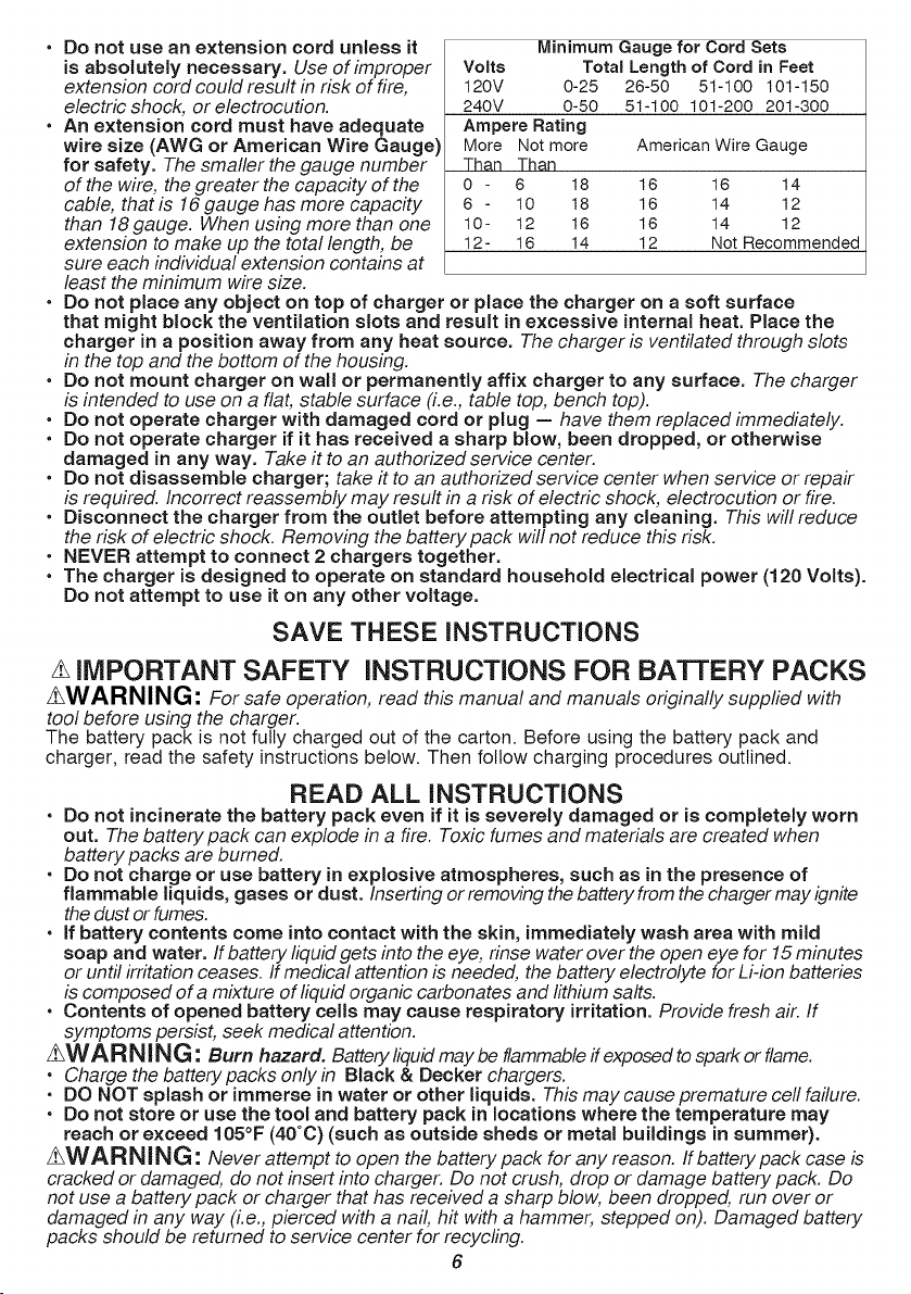
• Do not use an extension cord unless it
is absolutely necessary. Use of improper
extension cord could result in risk of fire,
electric shock; or electrocution.
• An extension cord must have adequate
wire size (AWG or American Wire Gauge)
for safety. The smaller the gauge number
of the wire, the greater the capacity of the
cable, that is 16gauge has more capacity
than 18 gauge. When using more than one
extension to make up the total length, be
Volts
120V 0-25
240V 0-50
Ampere Rating
More Not more
Than Than
o - 6 18
6 - lO 18
10- 12 16
12- 16 14
Minimum Gauge for Cord Sets
Total Length of Cord in Feet
26-50 51-100 101-150
51-100 101-200 201-300
American Wire Gauge
16 16 14
16 14 12
16 14 12
12 Not Recommended
sure each individual extension contains at
least the minimum wire size.
• Do not place any object on top of charger or place the charger on a soft surface
that might block the ventilation slots and result in excessive internal heat. Place the
charger in a position away from any heat source. The charger is ventilated through slots
in the top and the bottom of the housing.
• Do not mount charger on wall or permanently affix charger to any surface. The charger
is intended to use on a flat, stable surface (i.e., table top, bench top).
• Do not operate charger with damaged cord or plug -- have them replaced immediately.
• Do not operate charger if it has received a sharp blow, been dropped, or otherwise
damaged in any way. Take it to an authorized service center.
• Do not disassemble charger; take it to an authorized service center when service or repair
is required. Incorrect reassembly may result in a risk of electric shock; electrocution or fire.
• Disconnect the charger from the outlet before attempting any cleaning. This will reduce
the risk of electric shock: Removing the battery pack will not reduce this risk:
• NEVER attempt to connect 2 chargers together.
• The charger is designed to operate on standard household electrical power (120 Volts).
Do not attempt to use it on any other voltage.
SAVE THESE iNSTRUCTiONS
IMPORTANT SAFETY iNSTRUCTIONS FOR BA'FrERY PACKS
z_WARNING: For safe operation, read this manual and manuals originally supplied with
tool before using the charger.
The battery pack is not fully charged out of the carton. Before using the battery pack and
charger, read the safety instructions below. Then follow charging procedures outlined.
READ ALL iNSTRUCTiONS
• Do not incinerate the battery pack even if it is severely damaged or is completely worn
out. The battery pack can explode in a fire. Toxic fumes and materials are created when
battery packs are burned.
• Do not charge or use battery in explosive atmospheres, such as in the presence of
flammable liquids, gases or dust. Inserting or removing the battery from the charger may ignite
the dust orfumes.
• if battery contents come into contact with the skin, immediately wash area with mitd
soap and water. If battery liquid gets into the eye, rinse water over the open eye for 15 minutes
or until irritation ceases. If medical attention is needed, the battery electrolyte for Li-ion batteries
is composed of a mixture of liquid organic carbonates and fithium salts.
• Contents of opened battery cells may cause respiratory irritation. Provide fresh air. If
symptoms persist, seek medical attention.
_W A RN!NG: Burn hazard. Battery liquid may be flammable if exposed to spark or flame.
• Charge the batterypacks onlyin Black & Decker chargers.
• DO NOT splash or immerse in water or other liquids. This may cause premature ceil failure.
• Do not store or use the tool and battery pack in locations where the temperature may
reach or exceed 105°F (40°C) (such as outside sheds or metal buildings in summer).
_WARNING: Never attempt to open the battery pack for any reason. Ifbattery pack case is
cracked or damaged, do not insert into charger. Do not crush, drop or damage battery pack. Do
not use a battery pack or charger that has received a sharp blow, been dropped, run over or
damaged in any way (i.e., pierced with a nail, hit with a hammer, stepped on). Damaged battery
packs should be returned to service center for recycling.
6

zhWARNING: Fire hazard. Do not store or carry battery so that metal objects can contact
exposed battery terminals. For example, do not place battery in aprons, pockets, tool boxes,
product kit boxes, drawers, etc., with loose nails, screws, keys, etc. Transporting batteries can
possibly cause fires if the battery terminals inadvertently come in contact with conductive
materials such as keys, coins, hand tools and the like. The US Department of Transportation
Hazardous Material Regulations (HMR) actually prohibit transporting batteries in commerce or on
airplanes (i.e., packed in suitcases and carry-on luggage) UNLESS they are properly protected
from short circuits. So when transporting individual batteries, make sure that the battery terminals
are protected and weft insulated from materials that could contact them and cause a short circuit.
NOTE: M-ION batteries should not be put in checked baggage.
STORAGE RECOMMENDATIONS
1. The best storage place is one that is cool and dry away from direct sunlight and excess
heat or cold.
2. Long-term storage will not harm the battery pack or charger as long as the battery is not depleted.
CHARGING PROCEDURE
Black and Decker chargers are designed to charge Black and Decker battery packs in 5-10
hours depending on the pack being charged: LBXR2020 (5 hrs), LB2X4020 (10 hrs). The
standard charger provided wilt charge a fully depleted battery in about 10 hours.
1. Plug the charger into an appropriate outlet before inserting the battery pack.
2. Slide the charger onto the battery pack as shown in figure B.
3. The green LED will flash indicating that the battery is being charged.
4. The completion of charge is indicated by the green LED remaining on continuously. The
pack is fully charged and may be used at this time or left on the charger.
Recharge discharged batteries as soon as possible after use or battery life may be
greatly diminished.
LEAVING THE BATTERY IN THE CHARGER
The charger and battery pack can be left connected with the green LED glowing indefinitely.
The charger will keep the battery pack fresh and fully charged.
IMPORTANT CHARGING NOTES
1. Longest life and best performance can be obtained if the battery pack is charged when the
air temperature is between 60°F and 80°F (16°- 27°C). DO NOT charge the battery pack in an
air temperature below +40°F (+4.5°C), or above +105°F (+40.5°C). This is important and will
prevent serious damage to the battery pack.
2. The charger and battery pack may become warm to touch while charging. This is a normal
condition, and does not indicate a problem. To facilitate the cooling of the battery pack after
use, avoid placing the charger or battery pack in a warm environment such as in a metal
shed, or an uninsutated trailer.
3. If the battery pack does not charge properly:
a. Check current at receptacle by plugging in a lamp or other appliance.
b. Check to see if receptacle is connected to a light switch which turns power off when
you turn out the lights.
c. Move charger and battery pack to a location where the surrounding air temperature is
approximately 60°F - 80°F (16° - 27°C).
d. If charging problems persist, take the tool, battery pack and charger to your local
service center.
4. The battery pack should be recharged when it fails to produce sufficient power on jobs
which were easily done previously. DO NOT CONTINUE to use under these conditions.
Follow the charging procedure. You may also charge a partially used pack whenever you
desire with no adverse affect on the battery pack.
5. Foreign materials of a conductive nature such as, but not limited to, steel wool, aluminum
foil, or any buildup of metallic particles should be kept away from charger cavities. Always
unplug the charger from the power supply when there is no battery pack in the cavity. Unplug
charger before attempting to clean.
6. Do not freeze or immerse charger in water or any other liquid.
zhWARNING: Shock hazard. Do not allow any liquid to get inside charger. Never attempt to
open the battery pack for any reason. If the plastic housing of the battery pack breaks or cracks,
return to a service center for recycling.
7

iNSTALLiNG AND REMOVING THE BATTERY PACK
zLWARNING: Make certain the lock-off button is engaged to prevent switch actuation before
removing or installing battery.
TO iNSTALL BATTERY PACK:
Insert battery pack (2)firmly intotrimmer until anaudible click is heard as shown in figure C. Ensure
batterypack is fully seated and fully latched into position.
TO REMOVE BATTERY PACK: Depressthe battery release buttonin the back ofthe battery pack and
pull batterypack out oftrimmer.
This product can accept any of the batteries and chargers listed in the chart below.
M=ION Battery Packs and Chargers
Description Cat. #
Batteries: LI-ION LBX20
LBXR20
LBXR2020
LB2X4020
Chargers: LI-ION LCS1620
L2AFCBST
L2AFC
ASSEMBLY AND ADJUSTMENT
iNSTALLiNG THE GUARD
z_WARNING- REMOVE THE BATTERY BEFORE ATTEMPTING TO ATTACH THE GUARD,
EDGE GUIDE OR HANDLE. NEVER OPERATE TRIMMER WITHOUT GUARD FIRMLY IN
PLACE. THE GUARD MUST ALWAYS BE ON THE TRIMMER TO PROTECT THE USER.
• Turn the trimmer upside down so that you are looking down at the spool cap (9).
• Remove the screw from the guard with a phillips screwdriver.
• Turn the guard (8) upside down and slide it fully onto the motor housing (6). Make sure the
tabs (10) on the guard engage the ribs (11) on the motor housing as shown in figure D. The
locking tab (25) should have snapped into the housing slot (26).
• Continue to slide the guard on until you hear it "snap" into place.
• Using a phillips screwdriver, insert the guard screw as shown in figure E to complete the
guard assembly.
• Once the guard is installed, remove the covering from the line cut-off blade, located on the
edge of the guard.
ATTACHING THE AUXILIARY HANDLE (FIGURES F & G)
• Push the auxiliary handle (3) onto the tube (10).
• Slide the bolt (11) into the hex-shaped hole of the handle and through to the opposite side.
• Tighten the knob (12) onto the bolt by turning it clockwise.
ADJUSTING THE POSiTiON OF THE AUXiLiARY HANDLE
The auxiliary handle can be adjusted to provide optimum balance and comfort.
• Loosen the knob (12) on the bolt (11) by turning it counter clockwise.
• Gently slide the auxiliary handle up or down the tube (10) to the desired height.
• Tighten the knob onto the bolt by turning it clockwise.
ADJUSTING THE HEIGHT OF THE TRIMMER (FIGURE H)
2_CAUTION: Adjust the length of the trimmer to obtain proper working positions as shown
in figure I1.
This trimmer has a telescopic mechanism, allowing you to set it to a comfortable height.
To adjust the height setting (figure H):
• Release the height adjust locking clamp (5).
• Gently pull the tube (10) up or down to the desired height.
• Close the height adjust locking clamp.

OPERATING iNSTRUCTiONS
zhWARNING: Always use proper eye protection that conforms to ANSI Z87.1 (CAN/CSA
Z94.3) while operating this power trimmer.
zLWARNING: Remove the battery before making any assembly, adjustments, or changing
accessories. Such preventive safety measures reduce the risk of starting the trimmer accidentally.
z_CAUTION: Before you begin trimming, only use the appropriate type of cutting line.
zhCAUTION: Inspect area to be trimmed and remove any wire, cord, or string-like objects
which could become entangled in the rotating line or spool. Be particularly careful to avoid any
wire which might be bent outwardly into the path of the trimmer, such as barbs at the base of
a chain link fence.
SWITCHING ON AND OFF
• To switch the trimmer on, pull the lock off button (13) (shown in inset, figure I) back toward
the battery (2) and then squeeze the trigger switch (1).
• To switch the trimmer off, release the trigger switch.
OPERATING THE TRIMMER
• With the unit on, angle unit and slowly swing the trimmer side to side as shown in figure [
• Maintain a cutting angle of 5° to 10° as shown in figure I1. Do not exceed 10° (figure 12).Cut
with the tip of the line. To keep distance from hard surfaces use edge guide (7).
• Maintain a minimum distance of 24 inches (609.6 ram) between the guard and your feet as shown
in figure I1. To acheive this distance adjust the overall height of the trimmer as shown in figure H.
CONVERT TO EDGING MODE
zLCAUTION: The wheeled edge guide should only be used when in the edging mode.
The trimmer can be used in trimming mode or edging mode to trim overhanging grass along
lawn edges and flower beds.
For edging, the trimmer head should be in the position shown in figure K. If it is not:
• Remove the battery from the trimmer.
• Press and hold the head-release button (14) as shown in figure J.
• While holding the auxiliary handle (3), rotate the head (6) counterclockwise.
• Release the head-release button.
NOTE: The metal shaft and housing wilt only rotate in one direction.
• To return to trimming position, rotate the head clockwise back to its original position.
• Release the head-release button.
NOTE: The Auto Feed System may not operate correctly if wheeled edge guide is not used.
NOTE: You will experience faster than normal cutting line wear if the edging wheel is positioned
too far from the edge with the cutting line positioned over the sidewalk or abrasive surface.
EDGING
AWARNING- When being used as an Edger, stones, pieces of metal and other objects can
be thrown out at high speed by the line. The trimmer and guard are designed to reduce the
danger. However, MAKE SURE that other persons and pets are at least 100 feet (30m) away.
Optimum cutting results are achieved on edges deeper than 2 inches (50 mm).
• Do not use this trimmer to create trenches.
• Using the edging wheel (7), guide the trimmer as shown in figure K.
• Position the edging wheel on the edge of the sidewalk or abrasive surface so the cutting
line is over the grass or dirt area to be edged.
• To make a closer cut, slightly tilt the trimmer.
ACCELERATOR SWITCH & RUNTIME EXTENSION MODE
This string trimmer gives you the choice to operate at a more efficient speed to extend the
runtime for larger jobs, or accelerate the trimmer speed for high-performance cutting (figure L).
• To extend runtime, pull the runtime extender switch (4) back toward the battery (2) into
position #1. This mode is best for larger projects that require more time to complete.
• To accelerate the trimmer, push the runtime extender switch forward toward the trimmer
head (6) into position #2. This mode is best to cut through heavier growth and for
applications that need higher RPM.

NOTE:Wheninaccelerationmode(#2),runtimewillbedecreasedascomparedtowhen
trimmerisinextended runtime mode (#1).
CUTTING LiNE / LiNE FEEDING
Your trimmer uses .065 inch (1.65 ram) diameter, ROUND nylon line. During use, the
tips of the nylon lines wilt become frayed and worn and the special self feeding spool will
automatically feed and trim a fresh length of line. DO NOT BUMP trimmer on ground in
attempt to feed line or for any other purposes.
Cutting line will wear faster and require more feeding if the cutting or edging is done along
sidewalks or other abrasive surfaces or heavier weeds are being cut.
REPLACEMENT ACCESSORIES
z_CAUT_ON: Before you begin trimming, onty use the appropriate type of cutting line.
Use Black & Decker replacement spool Model No. AF-100, and replacement cap RC-100.
Reload nylon line (either bulk or prewound replacement spool) as shown in this manual.
• USE ONLY .065 inch (1.65 mm) DIAMETER ROUND NYLON MONOFILAMENT LINE.
Do not use serrated or heavier gauge line, as they will overload the motor and cause
overheating, and will not feed properly. This line is available at your local dealer or
authorized service center.
• Other replacement parts (guards, spool caps, etc.) are available through Black &
Decker service centers. To find your local service location call: 1-800-544-6986 or visit
www.blackanddecker.com.
z_WARNING: The use of any accessory not recommended by Black & Decker for use
with this trimmer could be hazardous.
REPLACING THE SPOOL
• Remove battery from trimmer.
• Depress the tabs (15) and remove the spool cap (9) from the spool housing (16) in the
trimmer head (figure M).
• For best results, replace spool with Black & Decker model # AF-100.
• Grasp empty spool with one hand and spool housing with other hand and pull spool out.
• If lever (17) in base of housing becomes dislodged, replace in the position as shown in
figure N before inserting new spool into housing.
• Remove any dirt and grass from the spool and housing.
• Unfasten the end of the cutting line and guide the line into the eyelet (19) figure O.
• Take the new spool and push it onto the boss (18) (figure N) in the housing. Rotate the
spool slightly until it is seated. The line should protrude approximately 5-3/8 inches (136mm)
from the housing.
• Align the tabs on the spool cap with the slots (20) in the housing (figure O).
• Push the cap onto the housing until it snaps securely into place.
CAUTION" To avoid trimmer damage, if the cutting line protrudes beyond the trimming
blade, cut it off so that it just reaches the blade.
REWiNDiNG SPOOL FROM BULK LiNE (USE ONLY.065 IN. ROUND DIAMETER LINE)
Bulk line is also available for purchase from your local retailer. NOTE: Hand wound spools
from bulk line are likely to become tangled more frequently than Black & Decker factory
wound spools. For best results, factory wound spools are recommended.
To install bulk line, follow the steps below:
• Remove battery from trimmer.
• Remove the empty spool from the trimmer as described in "REPLACING THE SPOOL".
• Remove any remaining cutting line from the spool.
• Make a fold at the end of the cutting line at about 3/4 inch (19mm) (21). Feed the cutting
line into one of the line anchoring slots (22) as shown in figure P.
• Insert the 3/4 inch (19mm) end of the bulk line into the hole (23) in the spool adjacent to the
slot as shown in figure Q. Make sure the line is pulled tight against the spool as shown in
figure Q.
• Wind the cutting line onto the spool in the direction of the arrow on the spool. Make sure to
wind the line on neatly and in layers. Do not crisscross (figure R).
• When the wound cutting line reaches the recesses (24), cut the line. (figure Q).
• Fit the spool onto the trimmer as described in "REPLACING THE SPOOL".
10

THE RBRC TM SEAL
The RBRC TM (Rechargeable Battery Recycling Corporation) Seat on the LI-ION
battery (or battery pack) indicates that the costs to recycle the battery (or battery
pack) at the end of its useful life have already been paid by Black & Decker.
RBRC TM in cooperation with Black & Decker and other battery users, has
established programs in the United States to facilitate the collection of spent LI-ION batteries.
Help protect our environment and conserve natural resources by returning the spent LI-ION
battery to an authorized Black & Decker service center or to your local retailer for recycling.
You may also contact your local recycling center for information on where to drop off the spent
battery. RBRC TM is a registered trademark of the Rechargeable Battery Recycling Corporation.
MAINTENANCE
zLWARNING: To avoid serious injury, remove the battery from the trimmer before
performing any maintenance.
z_CAUTION: To assure product SAFETY and RELIABILITY, repairs, maintenance and
adjustment should be performed by authorized service centers or other qualified service
organizations, always using identical replacement parts.
1. Keep the air intake slots clean to avoid overheating.
2. Your trimmer line can dry out over time. To keep your line in top condition, store spare pre-
wound spools or bulk line in a plastic, sealable bag with a tablespoon of water.
3. Plastic parts may be cleaned by using a mild soap and a damp rag.
4. The line cutter on the edge of the guard can dull over time. It is recommended you
periodically touch-up the sharpness of the blade with a file.
TROUBLESHOOTING
TRIMMER RUNS SLOWLY
• Remove Battery from tool.
• Check that the spool housing can rotate freely. Carefully clean it if necessary.
• Check that the cutting line does not protrude more than approximately 5-3/8 inches (136mm)
from the spool. If it does, cut it off so that it just reaches the line trimming blade.
AUTOMATIC LiNE FEED DOES NOT WORK
• Remove Battery from tool.
• Remove the spool cap.
• Pull the cutting line until it protrudes approximately 5-3/8 inches (136mm) from the spool. If
insufficient cutting line is left on the spool, install a new spool of cutting line.
• Ensure that the line is not crisscrossed on the spool as detailed in figure R. If it is, unwind
the cutting line, then wind it back on the spool neatly so that the lines do not cross.
• Ensure the beginning of the cutting line is pulled tight against the spool as shown in figure Q.
• Align the tabs on the spool cap with the cut outs in the housing.
• Push the spool cap onto the housing until it snaps securely into place.
• If the cutting line protrudes beyond the trimming blade, cut it off so that it just reaches the blade.
If the automatic line feed still does not work or the spool is jammed, try the following suggestions:
• Carefully clean the spool and housing.
• Remove the spool and check if the lever in the spool housing can move freely.
• Remove the spool and unwind the cutting line, then wind it on neatly again. Replace the
spool into the housing.
SERVICE iNFORMATION
All Black & Decker Service Centers are staffedwith trained personnelto provide customerswith efficient
andreliable service. Whetheryou needtechnical advice, repair,or genuine factory replacement parts,
contactthe Black & Decker location nearestyou. To find your localservice location, call:
1-800-544-6986or visit www.blackanddecker.com
11

FULL TWO-YEAR HOME USE WARRANTY
Black & Decker (U.S.) Inc. warrants this product for two years against any defects in material
or workmanship. The defective product will be replaced or repaired at no charge in either of
two ways. The first, which will result in exchanges only, is to return the product to the retailer
from whom it was purchased (provided that the store is a participating retailer). Returns
should be made within the time period of the retailer's policy for exchanges (usually 30 to
90 days after the sale). Proof of purchase may be required. Please check with the retailer
for their specific return policy regarding returns that are beyond the time set for exchanges.
The second option is to take or send the product (prepaid) to a Black & Decker owned or
authorized Service Center for repair or replacement at our option. Proof of purchase may be
required. This warranty does not apply to accessories. This warranty gives you specific legal
rights and you may have other rights which vary from state to state orprovince to province.
Should you have any questions, contact the manager of your nearest Black & Decker Service
Center. Thisproduct is not intended for commercial use.
FREE WARNING LABEL REPLACEMENT: If your warning labels become illegible or are
missing, call 1-800-544-6986 for a free replacement.
LATIN AMERICA: This warranty does notapply to products sold in Latin America. For
products sold in Latin America, check country specific warranty information contained in the
packaging, call the local company or see the website for warranty information.
Imported by
Black & Decker (U.S.) Inc.,
701 E. Joppa Rd.
Towson, MD 21286 U.S.A.
12

TAJLLE-BORDURE/ COUPE-BORDURE{20V MAX*)
MODE D'EMPLOI
NUMC:RO DE MOD#LE
LST400, LST420
13

LIGNES DIRECTRICES EN MATII_RE DE SECURITE =DEFINITIONS
Itest important que vous lisiez et compreniez ce mode d'emptoi. Les inform.ations qu'il
contient concernent VOTRE SECURITE et visent A EVlTER TOUT PROBLEME. Les
symboles ci-dessous servent & vous aider & reconnaftre cette information.
z_DANG ER • Indique une situation dangereuse imminente qui, si elle n'est pas _vit6e,
causera la mort ou des graves blessures.
zLAVERTISSEMENT • Indique une situation potentiellement dangereuse qui, si elle
n'est pas 6vit6e, pourrait causer la mort ou de graves blessures.
z_ M_SE EN GARDE " Indique une situation potentiellement dangereuse qui, si elte
n'est pas 6vit6e, pourrait causer des blessures mineures ou mod6r_es.
MISE EN GARDE " utilis6 sans le symbole d'alerte _.la s6curit6, indique unesituation
potentiellement dangereuse qui, si elle n'est pas 6vit6e, peut r6sulteren des dommages _.la propri6t&
A AVERTISSEMENT : Iorsque t'utilisation d'appareils de jardinage 61ectriques, des
pr6cautions de s6curit6 de base doivent toujours _tre suivies pour r6duire les risques
d'incendie, d'_lectrocution et de blessures, notamment les suivantes.
z_AVERTISSEMENT " AVERTISSEMENTS DE SECURITi_ ET
DIRECTIVES DE PREMIERE IMPORTANCE
z_REDUCTION DES RISQUES DE BLESSURES :
Avant tout usage, s'assurer que tout utilisateur de cet outil lise et comprenne toutes les
directives de s6curit6 ainsi que I'information comprise dans le pr6sent manuel.
• Conserver ces directives et les examiner fr&quemment avant d'utiliser I'appareil ou de
donner des directives aux autres.
MISE EN GARDE : N6gtiger de se conformer aux recommandations d_crites dans la
section des informations importantes annutera la garantie.
z_AVERTISSEMENT : Certaines poussieres produites par cet outil contiennent des
produits chimiques reconnus par t'Etat de la Californie comme pouvant causer le
cancer, les anomalies congenitales et d'autres dangers pour la reproduction. Voici
quelques exemples de ces produits chimiques :
Pour reduire votre exposition & ces produits chimiques, porter un equipement de securite approuve
comme un masque anti-poussieres congu specialement pour filtrer les particules microscopiques.
zLAVERTISSEMENT : TOUJOURS porter des lunettes de securit& Les lunettes de vue ne
constituent PAS des lunettes de s6curit& Utiliser 6galement un masque facial ou anti-pous-
s.i_re si I'op6ration de d6coupe g6n_re de la pous.si_re. TOUJOURS PORTER UN
EQUIPEMENT DE PROTECTION HOMOLOGUE :
zL • protection des voles respiratoires conformes aux normes NIOSH/OSHA/MSHA.
la norme ANSi S12.6 ($3.19) lots de I'utilisation. Sous certaines conditions et la dur_e
d'utitisation, le bruit de ce produit peut contribuer & une perte auditive.
• compos6s pr6sents dans les engrais
• compos6s pr6sents dans les insecticides, herbicides et pesticides
• arsenic et chrome provenant de bois trait6 chimiquement
• protection oculaire conforme & la norme ANSI Z87.1 (CAN/CSA Z94.3);
AVERTISSEMENT : Toujours porter une protection auditive appropriee, conforme
BIEN LIRE ET COMPRENDRE TOUTES LES DIRECTIVES AVANT
D'UTILISER L'OUTIL
zLAVERTISSEMENTS:
• TOUJOURS PORTER UNE PROTECTION OCULAIRE - Porter des lunettes ou des
lunettes protectrices en tout temps Iorsque cet outil est branch&
• DlSPOSITIF DE PROTECTION - Ne pas utiliser cet outit sans les dispositifs de
protection en place.
• S'HABILLER DE MANIERE APPROPRIEE - Ne pas porter de v_tements amptes ni de
bijoux. Its peuvent s'enchev_trer dans les pieces mobiles. Des gants en caoutchouc et des
14

chaussures ad_quates b. semelles en caoutchouc sont recommand6s Iors de travaux A
I'ext@ieur. Ne pas utitiser I'outil avec les pieds nus ou des sandales ouvertes. Porter des
pantalons longs pour prot6ger vos jambes. Se couvrir les cheveux s'ils sont longs.
• FIL EN NYLON - Tenir le visage, les mains et pieds 19indu fil de nylon rotatif en tout temps.
• LE FIL EN ROTATION EXECUTE UNE COUPE - Etre attentif lots de tailtage autour de
griltages et de ptates-bandes.
• TENIR ELOIGNE TOUS LES SPECTATEURS - ,A,une distance s6curitaire de I'aire de
travail, particutierement les enfants.
• AVERTISSEMENT IMPORTANT : Iorsque I'outil est utitis6 comme coupe bordure, des
pierres, morceaux de m6tat et autres objets peuvent _tre projet6s & haute vitesse par le
fit. L'outil et le dispositif de protection sont con_;us pour r6duire le risque. Toutefois, les
pr6cautions sp6ciates suivantes doivent _tre prises : S'ASSURER que toute personne et
animaux sont _loign_s d'au moins 30 m (100 pi).
• POUR RleDUIRE LE RISQUE de btessures par ricochet, travaillez en vous 61oignant de tout
objet solide tel un mur, des marches, de grosses pierres, d'arbres, etc. Soyez tres prudent
19rsde travaux pres d'objets solides et, le cas 6ch6ant, taittez ou coupez manuellement.
• EVlTER LES DEMARRAGES AOClDENTELS - Ne pas transporter d'outit branch6 avec le
doigt sur la d6tente.
• NE PAS FORCER L'OUTIL - & tourner & une vitesse plus rapide que celle pour laquelle it
est capable de couper efficacement.
• UTILISER LE BON OUTIL - Ne pas utitiser cet outil pour tout autre type de travail sauf pour
celui pour lequet il est pr_vu.
• NE PAS TROP TENDRE LES BRAS - Conserver son 6quilibre en tout temps.
• OUTIL ENDOMMAGle - Si vous frappez ou devenez enchev@rer dans un objet, arr_tez
imm6diatement I'outit, d6branchez-le puis inspectez pour toute trace de dommages qui
devront @re r6par6s avant une autre utitisation. Ne pas utiliser avec un moyeu ou une
bobine bris_s.
• DI_BRANCHER L'OUTIL - Lorsque inactJf,Iors de remplacement de fil ou avant un nettoyage.
• EVITER LES CONDITIONS ENVIRONNEMENTALES DANGEREUSES - Ne pas utiliser d'outJls
61ectriquesdans des lieux humides ou mouill6s. Suivre toutes les directives de ce mode d'emploi pour
uneutJlisatJonad6quate de votre outJl.Ne pas utJliserI'outJlsous la pluie.
• NE PAS UTILISER d'outJls61ectriquesportatifs dans un milieu gazeux ou d6flagrant. Les moteurs de
ces outils produisentnormalement des 6.tincellesqui pourraient enf!ammer des vapeurs.
• RANGER LES OUTILS INUTILISES A L INTERIEUR - Lorsqu ils ne sont pas utilis6s, les outils
doivent @re rang6s & I'int@ieur, dans un endroit sec et verrouill6, hors de port6e des enfants.
• #TRE VIGILANT - Surveitler le travail effectu6. Faire preuve de jugement. Ne pas utiliser
I'outit en cas de fatigue.
• PII_CES DE RECHANGE - Pour r6parer, n'utitiser que des pieces de rechange identiques.
• PRENDRE SOIN DES OUTILS ELECTRIQUES - Suivre les directives figurant & la
section Entretien. Inspecter r6guli_rement les raltonges 61ectriques et remplacer si
endommag_es. Maintenir les poign6es seches, propres et exemptes d'huile et de graisse.
• VERIFIER LES PIECES ENDOMMAGEES - Avant toute utilisation utt@ieure de I'appareit
6tectrique, un dispositif de protection endommag6, ou toute autre piece endommag6e,
doit _tre examin6 soigneusement afin d'assurer un fonctionnement ad6quat selon sa
fonction pr6vue. V@ifier I'alignement des pi_ces mobiles, la pr6sence de grippage des
pi_ces mobiles, de rupture de pi_ces, la fixation et tout autre probl_me pouvant nuire au
fonctionnement de I'outit. Un dispositif de protection endommag6, ou toute autre piece
endommag6e, doit @re r6par6 ou remplac6 ad6quatement par un centre de r6paration
autoris6 _. moins d'un avis contraire indiqu6 dans le present mode d'emploi.
• NE PAS immerger I'outit dans I'eau ou I'arroser au boyau. EVITER la p6n_tration de tout
liquide dans I'outit.
• NE PAS ranger t'outit sur des engrais ou des produits chimiques ou pros de ceux-ci.
• NE PAS nettoyer avec un nettoyeur & pression.
• Maintenez les gardes en place et en 6tat de marche.
• Garder les mains et les pieds de la zone de coupe.
z_AVERTISSEMENT : Ne pas utiliser tondeuse si la gb,chette ne tourne pas la tondeuse ou le
d6sactiver. Toute coupe qui ne peut 6tre contr616avec la g&chette est dangereux et dolt 6tre r6par6.
CONSERVE ESTASINSTRUCClONES
15

SYMBOLES
• L'6tiquette appos6e sur votre outil pourrait comprendre les symboles suivants.
et leurs d#finitions sont indiques ci-apres :
V.................... volts
Hz .................. hertz
min ................. minutes
- - - ou DC...... courant continu
_) .................. Construction de classe I
[] ............... Construction de classe II
RPM ou .../min .......... tours a la minute
DESCRIPTION FONCTIONNELLE (FIGURE A)
1. D6tente 4. Duree extender
(mis b la terre)
2. Pile 5. Tendeur pour r_gter la hauteur
3. Poign6e auxiliaire 6. T@e de coupe
A.................. amp eres
W................. watts
'_ ou AC.....courant altematif
no ................ sous vide
@ .............. borne de mise a/a minute
z_ ............ symbole d'avertissement
7. Roue du guide de coupe
8. Guide de coupe
9. Bobine
Les symboles
DiRECTiVES DE S¢:CURITI IMPORTANTES POUR LES
CHARGEURS DE PILES
CONSERVER CES DiRECTiVES : ce mode d'emploi comprend d'importantes directives de
s6curit6 pour les chargeurs de p!les.
z_AVERTISSEMENT : Avant d utiliser le chargeur, lisez toutes les instructions et mises en
garde figurant sur le chargeur, la batterie et le produit utilisant la batterie.
• Avant d'utiliser le chargeur, lire toutes les directives et tousles avertissements figurant sur le
chargeur, le bloc-piles et le produit utilis6 avec le bloc-piles.
AVERTISSEMENT : risque de choc _lectrique. Eviter la p6n@ration de tout liquide dans le
chargeur.
Z-_AVERTISSEMENT : risque de brQlure. Pour r6duire le risque de btessures, charger
uniquement des piles Black & Deckerconseill6es. D'autres types de piles peuvent exploser et
provoquer des blessures corporelles et des dommages.
z-_MISE EN GARDE : dans certaines circonstances, Iorsque le chargeur est branch6 au bloc
d'alimentation, le chargeur peut _tre court-circuit6 par des corps 6trangers conducteurs tels
que, mais sans s'y limiter, la laine d'acier, le papier d'atuminium ou toute accumulation de
particules m6taltiques. Its doivent _tre maintenus &distance des ouvertures du chargeur.
D6brancher syst6matiquement celui-ci si aucun bloc-piles n'y est ins@& D6brancher le
chargeur avant tout nettoyage.
z_AVERTISSEIVlENT :
• NE PAS tenter de charger le bloc=piles avec autre chose qu'un chargeur de marque. Les
chargeurs et blocs-piles sont congus sp4cialement pour fonctionner ensemble.
• Ces chargeurs ne sont pas destines a 6tre utilises a d'autres fins que celles de charger
les piles rechargeables conseillees Black & Decker. Toute autre utilisation risque de
provoquer un incendie, un choc 41ectrique ou une 41ectrocution.
• Proteger le chargeur de la pluie et de la neige.
• Tirer la fiche plut6t que le cordon pour debrancher le chargeur ou pour debrancher les
cordons a I'aJde de la fonctJon de guJrlande. Cela permet de r6duire le risque d'endommager
la fiche ou le cordon d'alimentation.
• S'assurer que le cordon est sJtue en lieu sQr de maniere ace que personne ne marche
ni ne trebuche dessus ou a ce qu'Jt ne soit
pas endommage ni soumJs a une tension.
• Ne pas utJliser de rallonge a moJns que
cela ne soit absolument necessaire.
L'utilisation d'une rallonge inad4quate risque
d'entrafner un incendie, un choc 41ectrique ou
une 41ectrocution.
• Pour la securit6 de I'utilisateur, utiliser
une rallonge de calibre adequat (AWG,
American Wire Gauge [calJbrage amerJcaJn
normalise des ills]). Plus le num6ro de
16
Calibre minirno para cables de extensi6n
Volts Longitud total del cable en pies
120V 0-25 26-50 51-1 O0 101-150
45,7m)
240V
Amperaje
M&s de
0 - 6
6 - 10
10 - 12
12 - 16
(0-7,6m) (7,6-15,2m) (15,2-30,4m) (30,4-
0-50 51-100 101-200 201-300
(0-15,2m) (15,2-30,4m)(30,4-60,gm)(60,9-91,4m)
No masde American Wire Gage
18 16 16 14
18 16 14 12
16 16 14 12
14 12 No serecomienda

calibredefilestpetitetplussacapacit#estgrande,parexempleuncalibre16aplusde
capadt#qu'uncalibre18.Siplusd'unerallongeestutilis#epourobtenirla Iongueur totale,
s'assurer que chaque rallonge pr#sente au moins le calibre de fil minimum.
• Ne pas mettre d'objet sur le chargeur ni mettre ce dernier sur une surface souple,
ce qui pourrait causer I'obstruction des fentes de ventilation et, du fait, provoquer
une chaleur interne excessive, leloigner le chargeur de toute source de chaleur. La
ventilation du chargeur se fait par les fentes pratiqu_es dans les parties sup_rieures et
inf6rieures du boftier.
• Ne pas installer le chargeur sur un tour ni le fixer de maniere permanente sur toute
surface. Le chargeur est destin_ _ une utilisation sur une surface plane et stable (c.-9-d. un
dessus de table ou d'_tabli).
• Ne pas faire fonctionner le chargeur si la fiche ou le cordon est endommage; les
remplacer imm_diatement.
• Ne jamais se servir d'un chargeur qui a subi un choc violent, qui est tombe par terre ou
qui est endommage de quelque maniere que ce soit. Le faire v_dfier clans un centre de
r6paration autoris_.
• Ne pas demonter le chargeur; confier I'entretien ou la r6paration de I'appareil _ un centre
de r6paration autoris_. Le remontage non conforme du chargeur comporte des risques de
choc _lectrique, d'61ectrocution ou d'incendie.
• Debrancher le chargeur avant de le nettoyer. Cela r6duira le risque de choc _lectrique. Le
risque ne sera pas _limin_ en enlevant simplement le bloc-piles.
• NE JAMAIS relier deux chargeurs ensemble.
• Le chargeur est congu pour 6tre alimente en courant domestique standard
(120 V). Ne pas utiliser une tension superieure pour le chargeur.
DIRECTIVES DE SI CURITE IMPORTANTES POUR LES
BLOCS=PILES
AVERTISSEMENT : Pour un fonctionnement sOr, tire le pr6sent manuel et les manuels
foumis avec I'outil avant d'utiliser le chargeur.
Le bloc-piles n'est pas compl_tement charg6 & la sortie de I'embaltage. Avant d'utiliser le bloc-
piles et le chargeur, lire les directives de s_curit_ ci-apr_s. Respecter ensuite les consignes de
chargement d_crites.
• Ne pas incinerer le bloc=piles, re@mes'il est tres endommage ou completement use,
car il pourrait exploser au contact des flammes. Des vapeurs et des matieres toxiques sont
d_gag_es Iorsque les blocs-piles sont incin_r_s.
• Ne pas charger ou utiliser de pile darts un milieu deflagrant, en presence de liquides, de
gaz ou de poussiere inflammables. InsUrer ou retirer la pile du chargeur peut enflammer de la
poussiere ou des _manations.
• Si le contenu de la pile entre en contact avec la peau, laver immediatement la zone
touchee au savon doux eta I'eau. Si le liquide de la pile entre en contact avec les yeux,
rincer I'oail ouvert _ I'eau pendant 15 minutes ou jusqu'9 ce que I'irritation cesse. Si des soins
m6dicaux sont n#cessaires, I'_lectrolyte des piles au fithium-ion est compos6 d'un m61ange de
carbonates organiques liquides et de sels de fithium.
• Le contenu des el6ments de pile ouverts peut provoquer une irritation respiratoire.
z EXposer la personne _ de I'air frais. Si les symptSmes persistent, obtenir des soins m6dicaux.
AVERTISSEMENT : Risque de br01ure. Le liquide de la pile peut s'enflammer s'il est
expos_ D des 6tincelles ou _ une flamme.
• Charger uniquement les blocs-piles au moyen de chargeurs Black & Decker.
• NE PAS eclabousser le bloc-piles ni rimmerger dans I'eau ou dans tout autre Iiquide.
Cela peut entrafner une d_faillance pr_matur_e de I'_l_ment.
• Ne pas ranger ni utiliser I'outil et le bloc-piles dans un endroit o_ la temperature peut
atteindre ou depasser les 40 °C (105 °F) (comme dans les remises exterieures ou les
b_timents metalliques en ete).
z_AVERTISSEMENT : Ne jamais tenter dbuvrir le bloc-piles pour quelque raison que ce soit.
Si le boftier du bloc-piles est fissur_ ou endommag_, ne pas I'ins_rer dans un chargeur. Ne pas
_craser, laisser tomber ou endommager le bloc-piles. Ne pas utiliser un bloc-piles ou un
chargeur qui a re?u un choc violent, qui est tomb_, a _t_ _cras_ ou est endommag_ de quelque
maniere que ce soit (p. ex. perc_ par un clou, frapp_ d'un coup de marteau, pitting). Les blocs-
piles endommag_s doivent _tre envoy_s au centre de r_paration pour _tre recycles.
LIRE TOUTES LES DIRECTIVES.
1Z

AVERTISSEMENT : Risque d'incendie. Ne pas ranger ou transporter les piles de mani_re &
ce que des objets m6talliques puissent entrer en contact avec les bornes expos6es des piles.
Par exemple, ne pas mettre de pile clans un tablier, une poche, une bofte _ outils, un boftier de
rangement, un tiroir, etc. contenant des objets tels que des clous, des vis ou des cl#s. Le
transport des piles peut causer un incendie si les bornes des piles entrent en contact
involontairement avec des mati_res conductrices comme des ct6s, de la monnaie, des outits
manuels et d'autres 6t6ments sembtables. Selon le reglement HMR du DOT (US Department of
Transportation Hazardous Material Regulations), il est effectivement interdit de transporter des
piles pour le commerce et dans les avions (c.-&-d. clans les valises et les bagages _ main) A
MOINS qu'elles ne soient bien protegees contre les courts-circuits. Pour le transport de piles
individuelles, on dolt donc s'assurer que les bomes sont prot#g6es et bien isol#es contre toute
matiere pouvant entrer en contact avec dies et provoquer un court-circuit. REMARQUE : Itne
faut pas laisser de piles au LI-ION clans les bagages enregistr6s.
RECOMMANDATIONS EN MATIERE DE RANGEMENT
1. Le meilleur endroit de rangement est celui qui est frais et sec, loin de toute lumiere directe
et prot6g6 d'une temp6rature extreme (chaleur ou froid).
2. El almacenamiento prolongado no dafiar& el paquete de baterias o el cargador, siempre y
cuando la bateria no est6 completamente descargada.
PROCI_DURE DE CHARGE
Les chargeurs Black and Decker sont con£us pour charger les blocs-piles Black and Decker
darts un d61ai de 5 & 10 heures selon le bloc-piles & charger : LBXR2020 (5 heures),
LB2X4020 (10 heures). Le chargeur standard fourni chargera une pile completement 6puis6e
en 10 heures environ.
1. Brancher le chargeur darts une prise appropri6e avant d'ins6rer le bloc-piles.
2. Ins6rer le bloc-piles darts le chargeur comme le montre la figure B.
3. Le voyant DEL vert clignotera indiquant ainsi que la pile est en cours de charge.
4. La fin de la charge est indiqu6e par le voyant DEL vert qui demeure allum&
Le bloc-piles est charg6 & plein et peut _tre utilis6 ou laiss6 sur le chargeur.
Recharger lea piles epuis6es aussit6t que possible apres leur utilisation pour prolonger
leur duree de vie.
PILE LAISSEE DANS LE CHARGEUR
Le chargeur et le bloc-piles peuvent _tre laiss6s branch6s, le voyant DEL vert demeurant
altum& Le chargeur maintiendra le bloc-piles en bon 6tat et completement charg&
REMARQUES IMPORTANTES SUR LE CHARGEMENT
1. Pour augmenter la dur6e de vie du bloc-piles et optimiser son rendement, le charger &
une temp6rature situ6e entre 16 et 27 °C (60 et 80 °F). NE PAS charger le bloc-piles &des
temp6ratures inf6rieures & 4,5 °C (40 °F) ou sup6rieures &40,5 °C (105 °F). Ces consignes
sont importantes et permettent d'@viter d'endommager gravement le bloc-piles.
2. Le chargeur et le bloc-piles peuvent devenir chauds au toucher pendant la recharge. I1
s'agit d'un 6tat normal et cela n'indique pas un probteme. Pour faciliter le refroidissement du
bloc-piles apres son utitisation, 6viter de mettre le chargeur ou le bloc-piles darts un endroit
chaud comme darts une remise m6tatlique ou une remorque non isol6e.
3. Si le bloc-piles ne se charge pas ad6quatement, on dolt :
a. V_rifier le courant & la prise en branchant une lampe ou un autre appareil _lectrique.
b. V_rifier si la prise est reli6e &un interrupteur d'6clairage qui coupe le courant au
moment d'6teindre la lumi_re.
c. D6placer le chargeur et te bloc-piles & un endroit oQ la temp6rature ambiante est entre
16 °C et 27 °C (60 °F et 80 °F).
d. Si le probl_me persiste, apporter ou envoyer I'outit, le bloc-piles et le chargeur au
centre de r6paration de votre r6gion.
4. Le bloc-piles dolt _tre recharg6 Iorsqu'il n'arrive pas & produire suffisamment de puissance
pour des travaux qui 6talent facilement r6alis6s auparavant. NE PAS CONTINUER & utiliser
le bloc-piles dans ces conditions. Suivre les proc6dures de charge. On peut 6galement
recharger & tout moment un bloc-piles partiellement d6charg6 sans affecter sa Iong6vit&
5. Tout corps _tranger conducteur, tel que notamment ta laine d'acier, le papier d'aluminium
ou toute accumulation de particutes m_tatliques, dolt _tre maintenu &distance des ouvertures
du chargeur. D_brancher syst_matiquement celui-ci si aucun bloc-piles n'y est ins_r&
D_brancher le chargeur avant tout nettoyage.
18

6. Ne pas congeler le chargeur, I'immerger dans I'eau ou dans tout autre liquide.
AVERTISSEMENT : Risque de choc 61ectrique.E-viterla p6n#tration de tout liquide dans le
chargeur. Nejamais tenter dbuvrir le bloc-piles pour quetque raison que ce soil Si le boftier en
ptastique du bloc-piles est bris6 ou fissure, le retoumer _ un centre de r#paration pour qu'il soit recyct#.
iNSERTiON ET RETRAIT DU BLOC-PILES
z_AVERTtSSEMENT : S assurer que le bouton de verrouillage est bien engag4 pour
emp_cher I'utilisation de la d4tente avant la pose ou le retrait de la pile.
INSTALLATION DU BLOC-PILES : Inserer le bloc-piles dans I'outJl,jusqu'au fond et de maniere&
entendre un declJc(figure C). Assurer la batterJeest bJenen place et bien enclenche en position.
RETRAIT DU BLOC-PILES : Enfoncer le bouton de degagement du bloc-pilessitue au dos du bloc-piles,
puisretirer le bloc-piles de I'outil.
Ce produit est compatible avec tousles modules de piles et de chargeurs
6num6r_s dans le tableau ci-dessous.
BIocs-pJJes au M-iON et chargeurs cortes 3ondants
Description N° de cat.
Bloc-piles : LI-ION LBX20
Chargeur : pour piles au LI-ION LCS1620
LBXR20
LBXR2020
LB2X4020
L2AFCBST
L2AFC
CONFIGURATION DE L'ASSEMBLAGE ET DES RC:GLAGES
POSE DU PARE=MAIN
AVERTJSSEMENT : RetJrer JapiJede J'outJl avant d'esaayer de fixer Jepare-main, le guide
de coupe ou Japoignee. NE JAMAJS UTILJSER L'OUTIL SANS LE PARE-MAIN SOUDEMENT
FJXE. Le pare-main doit toujours _tre en place aur FoutJl pour proteger I'operateur.
• Mettre le taitle-bordure b.I'envers de mani@e &voir le couvercle de la bobine (9).
• Retirer la vis de la garde avec un toumevis Phillips.
• Mettre le pare-main (8) & I'envers et le glisser sur le bottler du moteur (6). S'assurer que
les pattes (10) du dispositif de protection engagent les nervures (11) du bottler du moteur
comme dans I'iltustration (figure D). La patte de verrouillage (25) dolt @re enclench6e dans
le Iogement de bottler (26).
• Continuer de gtisser le pare-main jusqu'_, ce qu'il ,, s'enclenche _ en position.
• A I'aide d'un toumevis cruciforme, ins@er la vis du pare-main comme I'illustre la figure E
pour terminer I'assemblage du pare-main.
• Une lois le pare-main install6, retirer I'enveloppe de la lame, pour la coupe du ill, situ6e sur
le bord du pare-main.
FIXATION DE LA POIGNEE AUXILIAIRE (FIGURES F ET G)
• Pousser la poign6e auxiliaire (3) sur le tube (10).
• Extraire le boulon (11) dans letrou de forme hexagonale de la poignee et A travers le c6t6 oppose.
• Serrer le bouton (12) sur le bouton en le toumant dans le sens horaire.
REGLER LA POSITION DE LA POIGNEE AUXILIAIRE
La poign6e auxiliaire peut _tre r6gl6e pour assurer un 6quitibre et un confort optimaux.
• Desserrer le bouton du bouton en le toumant dans le sens antihoraire.
• Monter ou descendre doucement la poign6e auxiliaire le long du tube, jusqu'& la hauteur souhait6e.
• Serrer le bouton sur le bouton en le tournant dans le sens horaire.
i_GLAGE DE LA HAUTEUR
MISE EN GARDE : R6glez la Iongueur de la tondeuse & obtenir des postes de travail
appropri6es, comme indiqu6 dans la figure I1.
Cet outil dispose d'un m6canisme t61escopique permettant de le r6gter & une hauteur
confortable. Pour r_gter la hauteur (figure H) :
19

• Rel&cher le tendeur pour r6gter la hauteur (5).
• Monter ou descendre doucement le tube (10) & la hauteur souhait6e.
• Fermer le tendeur pour r_gter la hauteur.
FONCTIONNEMENT
z_AVERTISSEMENT : Toujours utiliser une protection oculaire appropri6e conforme & la
norme ANSI Z87.1 (CAN/CSA Z94.3) Iors de I'utilisation de cet outit 6tectrique.
z_AVERTJSSEMENT : D6brancher la fiche de la source d'alimentation avant de proc6der au
montage, d'effectuer des r6glages ou de changer d'accessoire. Une telte mesure de s6curit6
pr6ventive r6duit le risque de mettre I'outil en marche accidentellement.
Z_MJSE EN GARDE : Avant de proc6der au taillage, s'assurer d'utitiser uniquement le type
de fit de coupe ad6quat.
z_.MISE EN GARDE : Inspecter la zone qui sera taill6e et retirer tout morceau de fil
m6tallique, de co rde ou d'objets similaires qui pourraient s'enchevetrer dans le fil rotatif ou
avec la bobine. Etre sp_cialement attentif et 6viter, sur le parcours de I'outil, tout fit courb6
vers I'ext@ieur comme les fils m6talliques au pied d'une cl6ture & mailtes Iosang_es.
MISE EN MARCNE ET ARRET
• Pour mettre en marche I'appareil, tirer le bouton de verrouiltage (13) (montr6 en encart figure
J)en direction de la pile (2) puis appuyer sur la d6tente (1).
• Pour 6teindre I'outit, rel&cher le levier de d_clenchement.
FONCTIONNEMENT DU TAILLE-BORDURES
• Tenir I'outit comme il est indiqu6 & la figure I.
• Maintenir un angle de coupe entre 5° et 10° comme N le montre la figure I1. Ne pas exc6der
10° (figure 12). Couper avec le bout du ill. Pour se tenir &distance des surfaces dures,
utitiser le guide de coupe (7).
• Maintenir une distance minimale de 609,6 mm (24 po) entre le dispositif de protection et vos
pieds, comme le montre la figure I1. Pour obtenir cette distance, r_gter la hauteur globale du
tailte-bordures comme le montre la figure H.
MODE DE COUPE=BORDURES
z._MISE EN GARDE : Le guide de coupe & roue dolt @re utilis6 uniquement en mode de
coupe en bordure.
Pour la coupe en bordure, la t@ede coupe dolt se trouver dans la position indiqu6e par la figure K.
Si ce n'est pas le cas :
• Retirer le bloc-piles de I'outil.
• Enfoncer le bouton de d6gagement de la t_te (14) et le maintenir dans cette position (figure J).
• Tout en tenant la poign6e auxiliaire (3), tourner la t@e (6) dans le sens antihoraire.
• Rel&cher te bouton de d6gagement de la t_te.
REMARQUE : La t_te ne pivote que dans un seul sens.
• Pour revenir & la position de coupe, tourner la t@e vers la droite pour la retourner & sa
position initiale.
REMARQUE : Le syst_me d'alimentation automatique risque de mal fonctionner si le guide de
coupe n'est pas utilis&
REMARQUE : Vous ferez I'exp6rience plusrapide que I'usurenormale coupe la ligne si la roue bordure
est plac6 trop loin du bord de laligne de coupe positJonn6sur letrottoir ou une surfaceabrasive.
COUPE EN BORDURE
z._AVERTISSEMENT : Iorsque utilis6 comme un coupe-bordure, des pierres, des morceaux
de m6tal et d'autres objets peuvent @re jet6s &grande vitesse par la ligne. La coupe et la
garde sont congus pour r6duire le danger. Cependant, s'assurer que d'autres personnes et
les animaux sont au moins 30m (100 pieds) de distance.
Les meilleurs r6sultats de coupe sont obtenus sur des bords de plus de 50 mm (2 po) de profondeur.
• Ne pas utitiser t'outil pour cr6er des bordures ou des tranch_es.
Avec la roue de coupe en bordure (7), guider I'outil comme il est indiqu6 & ta figure K.
• La position bordure de roue sur le bord du trottoir ou la surface abrasive de la ligne de
coupe est sur la zone de l'herbe ou de la salet6 & _tre bord_
• Pour couper de plus pr6s, incliner 16g_rement l'outit.
2O

COMMUTATEUR D'ACCELERATION ET MODE DE PROLONGATION DE LA DUREE
D'OPC_RATION
Ce taille-bordure & fil rotatif vous donne te choix d'op6rer & une vitesse plus efficace pour
prolonger la dur6e d'op6ration pour des travaux plus importants, ou d'acc616rer la vitesse de
coupe pour une coupe de haute performance (figure L).
• Pour prolonger la dur6e d'op6ration, tirer I'interrupteur de prolongation d'op6ration (4) en
direction de la batterie (2) en position de n° 1. Ce mode est le meilleur pour de grands
projets qui n6cessitent plus de temps pour terminer.
• Pour acc616rer le taitle-bordure, pousser I'interrupteur de prolongation d'op6ration en avant
vers la t6te du taille-bordure (6) en position n° 2. Ce mode est pr6f6rable pour couper &travers
une croissance plus Iourde et pour les applications qui ont besoin d'un r6gime plus 61ev6.
REMARQUE : En mode d'acc6t6ration (n° 2), la dur6e d'op6ration sera diminu6e par rapport
&quand le tailte-bordure est en mode d'op6ration prolong6e (n° 1).
FIL TRANCHANT / AVANCE DU FIL
Votre taille-bordure utilise un fil de nylon ROND de 1,65 mm (0,065 po) de diam_tre. En cours
d'utilisation, les extr6mit6s des ills de nylon s'effitocheront et s'useront. La bobine sp6ciale &
avance automatique de fit fournira et coupera automatiquement une nouvelte Iongueur de fit.
Le fit tranchant s'usera plus rapidement et exigera une plus grande quantit6 de fit si la coupe
ou le taillage s'effectue te tong de trottoirs ou d'autres surfaces abrasives ou si des broussailtes
6paisses sont coup6es. Le m6canisme 6volu6 d'alimentation automatis6e du fit per£;oit la
demande accrue de ill, foumit et coupe la bonne Iongueur de fil d_s qu'elle est n6cessaire. NE
PAS FRAPPER I'appareit sur le sol pour alimenter I'appareil ou pour toute autre raison.
ACCESSOIRES DE RECHANGE
z_MISE EN GARDE : Avant de proc6der au tailtage, s'assurer d'utitiser uniquement le type de
fil de coupe ad6quat.
Utiliser la bobine de rechange module AF-100 et le capuchon de rechange RC-100 de Black & Decker.
Recharger le fil de nylon (en vrac ou pr6-enroul6 sur la bobine de rechange) selon les directives
de ce mode d'emploi.
• UTILISER UNIQUEMENT UN FIL EN NYLON ROND DE 1,65 mm (0,065 po) DE
DIAMI_TRE. Ne pas utiliser de fil dentel6 ou de plus gros calibre, car ces ills surchargeront
le moteur et provoqueront une surchauffe. Ce fit est disponible aupr_s de votre d6taillant
local ou de votre centre de r6paration autoris6.
• D'autres pi_ces de rechange (pare-mains, couverctes de bobine, etc.) sont offertes aux
centres de r6paration Black & Decker. Pour trouver le centre de r6paration de votre r6gion,
composer le : 1=800=544-6986 ou consulter www.blackanddecker.com.
AVERTISSEMENT : L utilisation de tout accessoire non recommand6 par Black & Decker,
avec cet outit, pourrait s'av6rer dangereuse.
REMPLACER LA BOBINE
• Retirer la pile de I'outil.
• Enfoncer les languettes (15) et retirer le couvercle de la bobine (9) du bottler de la bobine
(16) log6 dans la t6te du taille-bordure (figure M).
• Pour obtenir des r6sultats optimaux, remplacer la bobine par une bobine de module AF-100
de Black & Decker.
• Tenir la bobine vide d'une main et le boftier de bobine de I'autre, puis sortir la bobine en
tirant dessus.
• Si le levier (17) (figure N) situ6 & la base du boftier se d6tache, le remettre & la bonne
position avant d'ins6rer la bobine neuve dans le bottler.
• Retirer I'herbe et les salet6s pr6sentes dans la bobine et le bottler.
• D6tacher I'extr6mit6 du fil de coupe et le faire passer dans I'oeillet (19), figure O.
• Prendre la bobine neuve et I'enfoncer sur la saillie (18) (figure N) du boftier. Faire pivoter
16g_rement la bobine jusqu'& ce qu'elte soit bien install6e. Le fil dolt sortir d'environ
136 mm (5 3/8 po) du boftier.
• Aligner les languettes du couvercle de la bobine sur les encoches (20) du boftier (figure O).
• Enfoncer le couvercle sur le boftier de mani@e & ce qu'il s'enctenche bienen place.
MISE EN GARDE : Pour 6viter d'endommager I'outil, si le fit d6passe la lame de coupe, le
couper de fa(?on & ce qu'il atteigne seutement la lame.
21

REMBOBINAGE DE LA BOBINE AVEC DU FIL EN VRAC(UTILJSER
UNIQUEMENT UN FIL ROND DE 1,65 MM (0,065 PO) DE DIAMETRE)
Le fit en vrac est 6galement offert par les d6taillants Iocaux. REMARQUE : Le fil en vrac
des bobines enroul6es #,la main est susceptible de s'enchev6trer plus souvent que le fit des
bobines enroul6es dans une usine Black & Decker. Pour obtenir des r6sultats optimaux, il est
recommand6 d'utiliser des bobines embobin6es #,I'usine.
Suivre les 6tapes ci-dessous pour installer du fil en vrac :
• Retirer la pile de I'outit.
• Retirer la bobine vide de I'outit comme le d6crit la section ,, REMPLACER LA BOBINE ,_.
• Retirer tout le reste de fil de coupe de la bobine.
• Replier I'extr6mit6 du fil de coupe d'environ 19 mm (3/4 po) (21). Ins6rer le fit de coupe dans
I'une des encoches d'ancrage (22) comme le montre ta figure P.
• Ins6rer I'extr6mit6 de 19 mm (3/4 po) du fit en vrac dans I'orifice (23) de la bobine, juste &
c6t6 de I'encoche comme le montre la figure Q. Assurez-vous que la ligne est tendue contre
la bobine comme illustr6 & la figure Q.
• Enrouler le fit de coupe sur la bobine dans le sens indiqu6 par la fleche inscrite sur la bobine.
Prendre soin d'enrouler le fit de fa(_on nette et ordonn6e par couches successives. Ne pas
croiser le fil (figure R).
• Couper le fil enrout6 Iorsqu'it atteint les encoches (24). (figure Q).
• Ajuster la bobine sur I'outil comme le d6crit la section ,, REMPLACER LA BOBINE ,>.
LE SCEAU SRPRC Mc
Le sceau SRPRC Mc(Soci6t6 de recyctage des piles rechargeables) sur la pile au
lithium-ion (ou sur le bloc-piles) indique que son co0t de recyclage (ou celui du
bloc-piles) A la fin de sa vie utile est d6jA pay6 par Black & Decker.
La SRPRC Mc,en c9ttaboration avec Black & Decker et d'autres utilisateurs de
piles, a 6tabti aux Etats-Unis des programmes facilitant le ramassage des piles
au LI-ION 6puis6es. Aidez-nous A prot6ger I'environnement et A conserver nos ressources
naturelles en retournant les piles LI-ION 6puis6es & un centre de r6paration
Black & Decker ou au d6tailtant de votre r6gion pour qu'eltes soient recycl6es. Vous pouvez
aussi communiquer avec le centre de recyclage de votre r6gion pour obtenir des informations
sur I'endroit ot_61iminer vos piles 6puis6es. SRPRC Mcest une marque de commerce d6pos6e de
la Soci6t6 de recyclage des piles rechargeables.
ENTRETIEN
z_AVERTISSEMENT: Pour 6viter des blessures graves, 6teindre et d6brancher I'outit avant
d'effectuer toute op6ration d'entretien.
z_MISE EN GARDE : Pour garantir la SECURITE et la FIABILITE du produit, les r6parations,
I'entretien et le r6glage doivent 6tre r6alis6s par un centre de r6paration autoris6 ou tout autre
centre de r6paration professionnel, et des pi_ces de rechange identiques doivent 6tre utitis6es.
1. Maintenir les orifices de ventilation d6gag6s pour 6viter la surchauffe.
2. Votre fit rotatif peut s6cher avec le temps. Pour tenir votre fil en excellente condition,
entreposer les bobines de rechange de fit pr6-enroul6 ou le fit en vrac dans un sac en
ptastique scell6 contenant 1'6quivalent d'une cuiller6e d'eau.
3. Les pi_ces en ptastique se nettoient avec un savon doux et un chiffon humide.
4. Le coupe-fil sur le bord du dispositif de protection peut s'emousser avec le temps. II est
recommande de s'assurer regulierement que la lame est bien tranchante en utilisant une lime.
DI PANNAGE
L'OUTIL FONCTIONNE LENTEMENT
• Retirer la pile de I'outit.
• V6rifier que le bower de la bobine peut toumer librement. Le nettoyer avec pr6caution si
n6cessaire.
• S'assurer que le fit de coupe sort d'au plus 136 mm (5 3/8 po) de la bobine. Le cas
6ch6ant, le couper afin que sa Iongueur atteigne juste la lame de coupe pour le ill.
L'ALIMENTATION AUTOMATIQUE NE FONCTIONNE PAS
• Retirer la pile de I'outil.
• Entever le capuchon de la bobine.
• Tirer sur le fil de coupe de mani_re &ce qu'it sorte d'environ
22

136 mm (5 3/8 po) de la bobine. Si la Iongueur de fil restant sur la bobine est insuffisante,
installer une nouvelle bobine de fil.
• S'assurer que le fit n'est pas entrecrois6 sur la bobine comme I'illustre la figure R. Si c'est
le cas, d6router le fil de coupe, puis I'enrouter de nouveau sur la bobine de fa(_on ordonn6e,
de maniere A ne pas entrecroiser les fils.
• S'assurer que le d6but de la ligne de coupe est tir6e serr6 contre la bobine comme ittustr6
&la figure Q.
• Aligner les languettes, Iog6es sur le couvercle de la bobine, sur les fentes pratiqu6es dans
le bottler.
• Enfoncer ta bobine sur le bottler de maniere A ce qu'elle s'enclenche bien en place.
• Si le fit de coupe d6passe la lame de coupe, le couper de fa(_on Ace qu'il atteigne
seulement la lame. Si I'alimentation automatique de fil ne fonctionne toujours pas ou si la
bobine se btoque, proc6der comme suit :
• Nettoyer avec pr6caution la bobine et son bottler.
• Retirer la bobine, puis v6rifier si le levier, situ6 dans le bottler de la bobine, peut se
d6ptacer librement.
• Retirer la bobine et d6router le fil de coupe, puis I'enrouler & nouveau de fa(_on
ordonn6e. Remettre la bobine dans le boftier.
INFORMATION SUR LES Ri PARATIONS
Tousles centres de r6paration Black & Decker sont dot6s de personnel qualifi6 en mati_re
d'outittage 61ectrique; ils sont donc en mesure d'offrir & leur clientele un service efficace
et fiable. Que ce soit pour un avis technique, une r6paration ou des pi_ces de rechange
authentiques install6es en usine, communiquer avec 1'6tabtissement Black & Decker le plus
pros de chez vous. Pour trouver 1'6tabtissement de r6paration de votre r6gion, consulter le
r6pertoire des Pages jaunes & la rubrique <,Outils 6tectriques _>ou composer le num6ro
suivant : 1=800=544-6986 ou consulter le site www.biackanddecker.com
GARANTIE COMPLETE DE DEUX ANS POUR UNE
UTILISATIQN DOMESTIQUE
Black & Decker (E.-U.) Inc. garantit ce produit pour une dur6e de deux ans contre tout d6faut
de mat6riau ou de fabrication. Le produit d6fectueux sera remptac6 ou r6par6 sans frais de
I'une des deux fa£_onssuivantes :
La premiere fa(?on consiste en un simple 6change chez le d6taitlant qui l'a vendu (pourvu qu'it
s'agisse d'un d6taillant participant). Tout retour dolt se faire durant la p6riode correspondant &
la politique d'6change du d6taillant (habituellement, de 30 &90 jours apres I'achat). Une preuve
d'achat peut 6tre requise. V6rifier aupr_s du d6taillant pour connaftre sa politique concemant
les retours hors de la p6riode d6finie pour les 6changes. La deuxi_me option est d'apporter ou
d'envoyer le produit (transport pay6 d'avance) & un centre de r6paration autoris6 ou &un centre
de r6paration de Black & Decker pour faire r6parer ou 6changer te produit, & notre discr6tion.
Une preuve d'achat peut 6tre requise. Les centres Black & Decker et les centres de service
autoris6s sont r6pertori6s dans tes pages jaunes, sous la rubrique <,Outils 61ectriques _>.
Cette garantie ne s'apptique pas aux accessoires. Cette garantie vous accorde des droits
16gaux sp6cifiques et vous pourriez avoir d'autres droits qui varient d'un Etat ou d'une province
&I'autre. Pour toute question, communiquer avec le directeur du centre de r6paration Black &
Decker le plus pros de chez vous. Ce produit n'est pas destin6 & un usage commercial.
REMPLACEMENT GRATUiT DES ETIQUETTES D'AVERTISSEMENT : si les 6tiquettes
d'avertissement deviennent illisibles ou sont manquantes, composer le 1=800=544-6986 pour
en obtenir le remplacement gratuit.
Imported by / Importe par
Black & Decker Canada Inc.
100 Central Ave.
Brockville (Ontario) K6V 5W6
23

DEPODADORA/ BORDEADORA(20V MAX*)
MANUAL DE INSTRUCCIONES
CATALOGO N °
LST400, LST420
24

PAUTAS DE SEGURIDAD/DEFINICIONES
Es importante que lea y comprenda este manual. La informaci6n que contiene se relaciona
con la proteccidn de SU SEGURIDAD y la PREVENCION DE PROBLEMAS. Los simbolos
que siguen se utilizan para ayudarlo a reconocer esta informaci6n.
Z_PELIGRO: indica una situaci6n de peligro inminente que, si no se evita, provocar& la
muerte o lesiones graves.
z_ ADVERTENCIA: indica una situaci6n de peligro potencial que, si
no se evita, provocar& la muerte o lesiones graves.
,/_ PRECAUC_(_)N: indica una situaci6n de peligro potencial que, si no se evita, provocar&
lesiones leves o moderadas.
AV_SO: utitizado sin el simbolo de aterta de seguridad indica una situaci6n de peligro
potencial que, si no se evita, puede provocar dados en la propiedad.
zLADVERTENClA: AI utilizar herramientas el6ctricas para el jardin, siempre se deben
tomar ciertas precauciones b&sicas de seguridad para minimizar el riesgo de incendio,
descarga el6ctrica y lesiones personates, entre elias:
ADVERTENClAS E INSTRUCClONES IlVlPORTANTES SOBRE SEGURIDAD
REDUCIR EL RIESGO DE LESIONES:
• Antes de usar, asegQrese de que todos los usuarios de esta herramienta lea y comprenda
todas las instrucciones y advertencias de seguridad incluidas en este manual.
• Guarde estas instru,cciones y reviselas con frecuencia antes de usar el aparato o para instruir a otros.
zLPRECAUCION: El no cumplir con las recomendaciones descritas en la secci6n
informaci6n importante sin efecto la garantia.
z_ADVERTENOIA: Parte det polvo generado pot este producto contiene
sustancias quimicas reconocidas pot el Estado de California como causantes de
cancer, defectoa congenitoa u otros problemas reproductivos. Algunos ejemplos de
estas sustancias quimicas:
Para reducir su exposici6n a estas sustancias quimicas, utitice el equipo de seguridad aprobado,
como m&scaras para polvo especialmente disedadas para filtrar particulas microsc6picas.
• compuestos en los fertilizantes
• compuestos en los insecticidas, herbicidas y pesticidas
• ars_nico y cromo de la madera con tratamiento quimico
_ADVERTENCIA: USE SIEMPRE LENTES DE SEGURIDAD. Los anteojos de uso
diario NO son lentes de seguridad. Utilice tambien mascaras faciales o para polvo si el
corte produce polvillo. UTILICE SiEMPRE EQUIPOS DE SEGURiDAD CERTIFICADOS:
• Protecci6n para los ojos seg0n la norma ANSI Z87.1 (CAN/CSA Z94.3)
• Protecci6n auditiva seg0n la norma ANSI $12.6 (S3.19)
• Protecci6n respiratoria segOn las normas NIOSH/OSHA/MSHA
z_ADVERTENCIA: Siempre use protecci6n auditiva adecuada cumple ANSI S12.6
($3.19) durante el uso. Bajo ciertas condiciones de duraci6n de uso, el ruido de este producto
puede contribuir a la p6rdida auditiva.
LEA TODAS LAS INSTRUCCIONES
z_ADVERTENCIA:
• SIEMPRE UTILICE PROTECCION PARA LOS OJOS: utilice gafas o anteojos de
seguridad en todo momento que esta herramienta est6 enchufada.
• PROTECTOR: nunca utilice esta herramienta sin el protector.
• UTILICE LA VESTIMENTA ADECUADA: no utilice ropa holgada ni joyas. Pueden
atascarse en las piezas m6viles. Se recomienda utilizar guantes de goma y calzado con
una suela de goma considerable al trabajar al aire libre. No opere la herramienta
descalzo ni con sandatias abiertas. Utilice pantalones largos para protegerse las piernas.
Rec6jase y cubra el cabello largo.
• CUERDA DE NYLON: mantenga la cara, las manos y los pies lejos de la cuerda de nylon
giratoria en todo momento.
• LA CUERDA GIRATORIA REALIZA UNA FUNCl0N DE CORTE: tenga precauci6n al podar
alrededor de pantallas y ptantas que desea.
25

• MANTFNGA ALFJADOS A TODOS LOS FSPFCTADORFS: a una distancia segura,
especialmente a los nifios.
ADVFRTFNClA IMPORTANTF: al utilizar la herramienta como Bordeadora, las piedras,
las piezas de metal y otros objetos pueden ser arrojados a alta velocidad por la acci6n
de la cuerda. La herramienta y el protector est&n disefiados para reducir el peligro. No
obstant.e, se deben tener en cuenta las siguientes precauciones especiales:
• ASFGURFSF de que las dem&s personas y mascotas est6n a no menos de 30 m (100
pies) de distancia.
• PARA RFDUCIR EL RIFSGO de lesiones por repercusi6n (rebote), trabaje lejos de
cualquier objeto s61ido cercano, como pared, escalones,piedras grandes, _.rboles, etc.
Tenga suma precauci6n al trabajar cerca de objetos s61idos y, cuando sea necesario, pode
o recorte los bordes en forma manual.
• FVITF EL ARRANQUF ACCIDENTAL: nunca transporte la herramienta enchufada con el
dedo en et interruptor.
• NO FUFRCF LA HFRRAMIFNTA: a una velocidad m&s r&pida de lavelocidad para la que rue
disefiada para cortaren forma eficaz.
• UTILICF LA HFRRAMIFNTA ADFCUADA: no utitice esta herramienta para untrabajo diferente
a aqu611ospara losque fue disefiada.
NO SF FSTIRF: conserve el equilibrio adecuado y mant6ngase parado correctamente en
todo momento.
• SF DFBF CONTAR CON LA PROTFCCION DE UN INTFRRUPTOR DE CORTF POR
FALLA A TIFRRA (GFCI, por sus siglas en ingles) en el o los circuitos o tomacorrientes
que se utitizar&n para el aparato. Fxisten recept&.cutos disponibles con protecci6n GFCI
incorporada ypueden utilizarse para esta medida de seguridad.
• NO MALTRATF EL CABLE: nunca transporte el aparato sosteni6ndolo por el cable ni tire
de 6ste para desconectarlo del recept&cuto. Mantenga el cable alejado del calor, el aceite y
los bordes afilados.
• PIFZAS DE RFPUFSTO: al realizar el mantenimiento, utilice Onicamente piezas de
repuesto id6nticas.
DANO A LA UNIDAD: si golpea la herramienta o 6sta se atasca con un objeto extrafio,
det6ngata de inmediato, desenchOfela, verifique que no se haya dafiado y repare cualquier
dafio antes de seguir utitiz&ndola. No opere la herramienta si la bobina o el
carrete est&n dafiados.
• DFSCONFCTF LA HFRRAMIFNTA: cuando no la utitice, al reemplazar la cuerda o antes
de limpiarla.
FVITFLAS CONDICIONFS AMBIFNTALFS PFLIGROSAS: no utitice herramientas
el6ctricas en lugares hOmedos o mojados. Siga todas tas instrucciones inctuidas en este
Manual de instrucciones para una operaci6n adecuada de la herramienta. No utilice la
herramienta bajo la Iluvia.
• NO OPFRF herramientas el6ctricas port&tiles en atm6sferas gaseosas o explosivas. Los
motores de estas herramientas normalmente chispean, y las chlspas pueden encender los vapores.
GUARDF LAS HFRRAMIFNTAS QUF NO SF UTIMOFN FN EL INTERIOR: cuando no
las utilice, tas herramientas deben guardarse en un lugar seco, alto o bajo Ilave, fuera del
alcance de los nifios.
• • MANTI_NGASF ALFRTA: No haga funcionar esta unidad siest& cansado, enfermo o bajo la
influencia del alcohol, drogas o medicamentos.
• CONSERVE LAS HFRRAMIFNTAS ADFCUADAMFNTF: siga las instrucciones en la
secci6n de mantenimiento. Mantenga los mangos secos, limpios y libres de aceite y grasas.
• VFRIFIQUF LAS PIFZAS AVFRIADAS: antes de volver a utilizar la herramienta, se debe
controtar cuatquier protecci6n u otra pieza que est6 averiada para determinar si funcionar&
correctamente y realizar& la funci6n para la que rue disefiada. Verifique la alineaci6n y la
sujeci6n de las piezas m6viles, la rotura de piezas, el montaje y cualquier otra condici6n
que pueda afectar el funcionamiento. Cualquier protecci6n u otra pieza que est6 dafiada
debe ser reparada correctamente o reemplazada por un centro de mantenimiento
autorizado, a menos que este manual indique otra cosa.
• NO sumerja la herramienta en agua ni la satpique con una manguera. NO permita que
ningOn liquido entre en ella.
• NO guarde la herramienta sobre o cerca de fertitizantes o productos quimicos.
• NO limpie con una lavadora a presi6n.
• Mantenga los protectores instalados adecuadamente yen funcionamiento.
Mantenga las manos y los pies alejados del &rea de corte.
z_ADVERTENOL_: No utitice la herramienta si el gatillo interruptor no enciende o
apaga la herramienta. Toda herramienta que no pueda controlarse mediante el gatitlo inter-
ruptor es petigrosa y debe repararse.
26

CONSERVE ESTAS INSTRUCCIONES
Slmbolos
• La etiqueta de su herramienta puede inctuir los siguientes sfmbolos. Los sfmbolos y sus
definiciones son los siguientes:
V................. voltios
Hz ............... hertz
min ............. minutos
- - - o DC .....corriente directa
Q ............... Construcci6n Clase I
A ............... amperios
W.............. vatios
o AC .....corriente altema
no.............. no velocidad sin carga
G .............. terminal a tierra
(mis _ la terre)
[] ............... ConstrucciSn de clase II
z_ ............ simbolo de alerta
RPM o .../min ....... revoluciones o minuto seguridad
DESCRIPCION DE LAS FUNCIONES (FIGURA A)
1. Interruptor 6. Cabezat de la podadora
2. Bateria 7. Rueda de gufa de borde
3. Mango auxiliar 8. Protector
4. Extensi6n de tiempo de ejecuci6n 9. Carrete
5. Abrazadera de bloqueo para ajuste de altura
z_INSTRUCCIONES DE SEGURIDAD IMPORTANTES PARA LOS
CARGADORES DE BATER[AS
CONSERVE ESTAS INSTRUCCIONES: Este manual contiene instrucciones de seguridad
importantes para los cargadores de baterias.
• Antes de utilizar el cargador, lea todas tas instrucciones y las prevenciones en el cargador, en
el paquete de baterias yen el producto que utiliza el paquete de baterias.
z_ADVERTENCIA: Riesgo de descarga el6ctrica. No permita que ningQn Ifquido entre en
el cargador.
z_PRECAUCI6N: Riesgo de quemaduras. Para reducir et riesgo de lesiones, cargue
sotamente baterfas Black & Decker. Otros tipos de baterias pueden estatlar y provocar dafios
ersonales y materi,_tes.
PRECAUCION: En determinadas circunstancias, con el cargador enchufado en el
tomacorriente, algunos materiales extraSos pueden provocar un cortocircuito en el cargador. Se
deben mantener lejos de las cavidades del cargador los materiales extraSos de naturaleza
conductora, entre los que se inctuyen la lana de acero, el papel de aluminio o cualquier
acumulaci6n de particulas met_.licas. Estos son s61oalgunos ejemplos y no constituyen una
lista taxativa. Siempre desenchufe el cargador del tomacorriente cuando no haya un paquete
de baterias en la cavidad. Desenchufe el cargador antes de intentar limpiarlo.
• NO intente cargar el paquete de baterfas con otros cargadores que no sean de la marca. Los
cargadores y los paquetes de baterfas estDn dise_ados especificamente para trabajarjuntos.
• Estos cargadores estan disefiados para utilizarse e×clusivamente con las baterias
recargables Black & Decker designadas. Otros usos pueden provocar riesgo de incendio,
descarga el_ctrica o electrocuciSn.
• No e×ponga et cargador a la Iluvia ni a ta nieve.
• Para desconectar el cargador o los cables para cadena de margarita, tire del enchufe en
lugar del cable. Esto reducir9 el riesgo de dadar el enchufe o el cable.
• Aseg_rese de que el cable eate ubicado de modo que no Io pise o se tropiece con 61 y
que no este sujeto a dafioe o tensiones
de alguna otra forma.
• No utilice un cable prolongador a menos
que sea absolutamente necesario. El uso
de un cable prolongador incorrecto puede
provocar riesgo de incendio, descarga el_ctrica
o etectrocuciSn.
• Para garantizar la seguridad, un cable
prolongador debe tenet un tamafio
de cable adecuado (AWG o Calibre de
conductor de Estados Unidos). Cuanto
Amperaje
27
Calibre mfnimo para cables de extensi6n
Volts Longitud total del cable en pies
120V 0-25 26-50 51-100 101-150
240V 0-50 51-100 101-200 201-300
M,_sde No ma.s de American Wire Gage
0 - 6 18 16 16 14
6 - 10 18 16 14 12
10 - 12 16 16 14 12
12 - 16 14 12 No se recomienda
(0-7,6m) (7,6-15,2m) (15,2-30,4m)(30,4-45,7m)
(0-15,2m) (15,2-30,4m)(30,4-60,em)(60,9-91,4m)

mgspequedoseaeln(Jmerodecalibredelconductor,mayorser9lacapacidadde/cable;
esdecir,uncalibre16tienemgscapacidadqueuncalibre18.Cuandoseutilizamgsdeuna
prolongaciSnparaIograrlaIongitudtotal,asegbresedequecadaprolongaciSntengalamedida
minimade/conductor.
• No coloque objetos en la parte superior del cargador ni coloque el cargador en una
superficie blanda que pueda bloquear las ranuras de ventilaciSn y provocar un calor
interno excesivo. Coloque el cargador en una posici6n alejada de cualquier fuente de
calor. El cargador se ventila a trav6s de ranuras en la parte superior e inferior de la cubierta.
• No monte el cargador en la pared ni Io instale en forma permanente sobre ninguna
superficie. El cargador est& disedado para ser utitizado sobre una superficie plana y estable
(p. ej., un banco o una mesa).
• No opere el cargador con cables o enchufes dafiados: reemplgcelos de inmediato.
• No opere el cargador si este ha recibido un golpe fuerte, se ha caido, o se ha dafiado
de cualquier otra manera. Ll_velo a un centro de mantenimiento autorizado.
• No desarme el cargador; Ilevelo a un centro de mantenimiento autorizado cuando se
requiera mantenimiento o una reparaci6n. El armado incorrecto puede implicar un riesgo
de descarga el_ctrica, electrocuciSn o incendio.
• Antes de limpiarlo, desconecte el cargador del tomaeorriente. Esto reducir& el riesgo de
descarga et6ctrica. Quitar el paquete de baterias no reducir& este riesgo.
• NUNCA intente conectar 2 cargadores juntos.
• El cargador esta disefiado para operar con corriente electrica domestica estandar (120
voltios). No intente utilizarlo con otto voltaje.
INSTRUCClONES IMPORT.ANTES DE SEGURIDAD PARA
LOS PAQUETES DE BATERIAS
z_ADVERTENCIA: Para un funcionamiento seguro, lea _ste y todos los manuales de
instrucciones incluidos con la herramienta antes de usar el cargador.
El paquete de baterias incluido en la caja no est& completamente cargado. Antes de utilizar el
paquete de baterias y el cargador, lea tas instrucciones de seguridad a continuaci6n. Luego,
siga los procedimientos de carga descritos.
LEA TODAS LAS INSTRUCClONES
• No incinere el paquete de baterias, aun si tiene dafios importantes o esta completamente
desgastado. El paquete de baterias puede explotar en el fuego. Cuando se queman los
paquetes de baterias, se generan vapores y materiales tSxicos.
• No cargue ni use la bateria en atm6sferas explosivas, como ambientes en los que hay
liquidos, gases o polvo inflamables. Insertar o retirar la bateria del cargador puede encender
el polvo o los vapores.
• Si et contenido de las baterias entra en contacto con la piel, tave el area de inmediato
con agua y jab6n suave. Si el Iiquido de la bateria entra en contacto con losojos, enjuague
con agua manteniendo los ojos abiertos durante 15 minutos o hasta que la irritaciSn cese. Si se
necesita atenciSn m6dica, el electrofito de/as baterias de iones de fitio contiene una mezcla de
carbonatos orggnicos liquidos y sales de fitio.
• El contenido de las celulas de la bateria abierta puede causar irritaci6n respiratoria.
Respire aire fresco. Si lossintomas persisten, busque atenciSn m6dica.
z_ADMERTENCIA: Riesgo de quemaduras. El liquido de la bateria puede encenderse
si se expone a chispas o llamas.
• Cargue los paquetes de baterias solamente en cargadores Black & Decker.
• NO salpique ni sumerja en agua u otros liquidos. Estopuede causaruna falla prematura de
las c_lulas.
• No almacene ni utilice la herramienta y el paquete de baterias en lugares en los que la
temperatura pueda alcanzar o superar los 40 °C (105 °F) (como en totdos al aire libre o
construcciones de metal en verano).
z_ADVERTENCIA: Nunca intente abrir el paquete de baterias por ningbn motivo. Si la
caja del paquete de baterias estb agrietada o dadada, no la introduzca en el cargador. No
comprima, deje caer ni dade el paquete de baterias. No utilice un paquete de baterias o un
cargador que haya recibido un golpe fuerte, se haya caido, est_ agotado o dadado de alguna
forma (por ejemplo, perforado con un clavo, golpeado con un martillo, pisado). Los paquetes de
baterias dadados deben devolverse alcentro de mantenimiento para su reciclado.
28

zLADVERTENCIA: Riesgo de incendio. No guarde o transporte la bateria de
ninguna manera que permita que los terrninales expuestos de la bateria entren en
contacto con objetos metaiicos. Por ejempto, no coloque la bateria en delantales, bolsillos,
cajas de herramientas, cajas de juegos de productos, cajones, con clavos, tomillos, Itaves
sueitos, etc. Transportar bater{as puede provocar incendios si los terminales de la bateria
entran en contacto accidentalrnente con rnateriales conductores como llaves, monedas,
herramientas rnanuales y similares. Las Normas para Materiates Peligrosos del
Departarnento de Transporte de los EE.UU. (HMR) concretamente prohiben transportar
baterias cornercialmente o en aviones (es decir, empacadas en maletas y equipaje de
mano) A MENOS que esten debidamente protegidas de cortocircuitos. Por Io tanto, cuando
transporte baterias individuales, asegQrese de que los terminales de la bateria est6n protegidos
y bien aistados de materiates que puedan hacer contacto y causar un cortocircuito. NOTA: Las
baterias de IONES DE LITIO no deben guardarse en el equipaje que se despacha.
RECOMENDACIONES CON RESPECTO AL ALMACENAMIENTO
1. Ei mejor tugar de aimacenamiento es uno que sea fresco y seco fuera de la luz solar
directa y de un exceso de cator o fr{o.
2. El almacenamiento prolongado no da_ar& el paquete de baterias o el cargador, siempre y
cuando la bateria no est6 completamente descargada.
PROCEDIMIENTO DE CARGA
Los cargadores Black and Decker est&n disedados para cargar paquetes de baterias Black
and Decker en un lapso de 5 a 10 horas, segQn el paquete que se carga: LBXR2020 (5
horas), LB2X4020 (10 horas). El cargador est&ndar provisto carga una bateria totalmente
descargada en alrededor de 10 horas.
1. Enchufe el cargador en un tomacorriente adecuado antes de insertar el paquete de baterias.
2. Deslice el cargador sobre el paquete de baterias como se muestra en la Figura B.
3. El indicador LED verde desteltar& indicando que ta bateria se est& cargando.
4. La bateria est& completamente cargada cuando el indicador LED verde permanece
encendido continuamente. El paquete est& completamente cargado y puede utitizarse en este
momento o dejarse en el cargador.
Despues del uso, recargue las baterias descargadas a la brevedad posible o de Io con-
trario la vida _til de las baterias podria acortarse en gran medida.
DEJAR EL PAQUETE DE BATER|AS EN EL CARGADOR
El cargador y el paquete de baterias se pueden dejar conectados con la luz verde encendida
indefinidamente. El cargador mantendr& el paquete de baterias como nuevo y completamente cargado.
NOTAS IMPORTANTES SOBRE LA CARGA
1. Se puede obtener una mayor duraci6n y 6ptimo rendimiento si se carga ei paquete de
baterias cuando la temperatura dei aire est& entre los 16°C y los 27°C (60°F y 80°F). NO
cargue el paquete de bateria con una temperatura ambiental por debajo de +4,5 °C
(+40 °F) o por encima de +40,5 °C (+105 °F). Esto es importante y evitar& dados graves en el
paquete de baterias.
2. El cargador y el paquete de baterias pueden estar calientes al tacto durante la carga.
Esto es una condici6n normal y no indica un problem& Para facilitar el enfriado del paquete
de baterias despu6s de su uso, evite colocar ei cargador o ei paquete de baterias en un
ambiente c&tido, como debajo de un totdo de metal o en un remolque sin aislamiento.
3. Si el paquete de baterias no se carga adecuadamente:
a. Revise el tomacorriente enchufando una I&mpara u otro aparato.
b. Vedfique si et tomacorriente est& conectado a un interruptor que corta la energia
cuando usted apaga ia luz.
c. Mueva el cargador y el paquete de baterias a un iugar donde la temperatura ambiental
sea alrededor de 16 °C a 27 °C (60 °F a 80 °F).
d. Si los probtemas de carga persisten, Ileve la herramienta, el paquete de baterias y el
cargador al centro de mantenimiento local.
4. Se debe recargar el paquete de baterias cuando no produc.e energia suficiente para
tareas que previamente realizaba con facilidad. NO CONTINUE utilizando ia herramienta en
estas condiciones. Siga el procedimiento de carga. Tambi6n se puede cargar un paquete de
baterias parcialmente agotado cuando se desee, sin ningQn efecto negativo sobre 6stas.
5. Se deben mantener lejos de las cavidades dei cargador los materiales extrados de
29

naturaleza conductora, entre los que se incluyen la lana de acero, el papel de aluminio
o cualquier acumutaci6n de particulas met&.licas. Siempre desenchufe el cargador del
tomacorriente cuando no haya un paquete de baterias en la cavidad. Desenchufe el cargador
antes de intentar limpiarlo.
6. No congele ni sumerja el cargador en agua ni en ningQn otro liquido.
z_ADVERTENCIA: Riesgo de descarga el6ctrica. No permita que ningQn liquido entre en
el cargador. Nunca intente abrir el paquete de baterias por ningOn motivo. Si la cubierta
protectora de plbstico del paquete de baterias se rompe o agrieta, devu_lvala a un centro de
mantenimiento para su reciclado.
INSTALACION Y RETIRO DEL PAQUETE DE BATERiAS
zLADVERTENCIA: AsegOrese de que el botSn de bloqueo est_ trabado para evitar el
accionamiento del interruptor antes de extraer o instalar la bateria.
PARA INSTALAR EL PAQUETE DE BATER|AS: Inserte el paquete de baterias (2) en la
herramienta hasta que est6 comptetamente asentado y se oiga un clic (figura C). AsegOrese
de bateria est,. completamente asentado y totalmente enganchado en su posici6n.
PARA EXTRAER EL PAQUETE DE BATERIAS: Para extraer el paquete de baterias: Oprima
el bot6n de liberaci6n de la bateria en la parte posterior del paquete de baterias y jale el
paquete de baterias hacia fuera de la herramienta.
Este producto es compatible con todas las baterias y los cargadores
detallados en el siguiente cuadro.
Cargadores y paquetes de baterias de U-ION
Descripci6n N.° de cat.
Bateria: LI-ION LBX20
LBXR20
LBXR2020
LB2X4020
Cargador: LI-ION LCS1620
L2AFCBST
L2AFC
EN,€_AMB LA DO/R EG ULACION ES
zLADVERTENCIA: DESENCHUFE LA HERRAMIENTA ANTES DE INSTALAR EL
PROTECTOR, LA GUiA DE BORDE O EL MANGO. NUNCA OPERE LA HERRAMIENTA
SiN EL PROTECTOR ADECUADAMENTE INSTALADO. EL PROTECTOR SIEMPRE DEBE
ESTAR INSTALADO EN LA HERRAMIENTA PARA PROTEGER AL USUARIO.
INSTALACION DEL PROTECTOR
• Coloque la podadora boca abajo de manera que vea la tapa del carrete (9).
• Quite el tornillo del protector con un destomillador phillips.
• Coloque el protector 8) boca abajo y desticeto en la cubierta del motor (6). AsegOrese de
que las leng0etas (10) del protector est6n sujetas alas varittas (11) de la cubierta del motor
como se muestra figura D. La leng0eta de bloqueo (25) debe estar encajado en la ranura
de alojamiento (26).
• Contint_e destizando el protector hasta que Io oiga encajar en su lugar.
• Con un destornillador Phillips, inserte el destomillador del protector, como se muestra en la
figura E para comptetar el ensambtaje del protector.
• Una vez instalado el protector, retire la cubierta de la hoja de corte de la cuerda ubicada en
el extremo del protector.
INSTALACION DEL MANGO AUXILIAR (FIGURAS F Y G)
• Empuje el mango auxiliar (3) sobre el tubo (10).
• Extraer el perno (11) en el orificio de forma hexagonal del mango y a traves de el lado opuesto.
• Ajuste la peritla (12) en el perno gir&ndolo en el sentido de las agujas del retoj.
AJUSTE DE LA POSICION DEL MANGO AUXILIAR
El mango auxiliar se puede ajustar para proporcionar 6ptimo equilibrio y comodidad.
3O

• Desserrez le bouton (12) sur le bouton (11) en tournant dans le sens antihoraire.
• Deslice suavemente el mango auxiliar (10) hacia arriba o hacia abajo por el tubo hasta la
altura deseada.
• Ajuste la peritla en el perno gir&ndota en el sentido de las agujas del retoj.
AJUSTE DE LA ALTURA DE LA HERRAMIENTA (FIGURA H)
z_ADVERTENCIA: R6glez la Iongueur de la tondeuse &obtenir des postes de travail
appropri6es, comme indiqu6 dans la figura I1.
Para ajustar la configuraci6n de altura (figura H):
• Suelte la abrazadera de btoqueo de ajuste de altura (5).
• Mueva suavemente del tubo (10) hacia arriba o hacia abajo hasta alcanzar la altura deseada.
• Cierre la abrazadera de bloqueo de ajuste de altura.
FUNCIONAMIENTO
zLADVERTENCIA: Siempre use protecci6n adecuada para los ojos que cumpla con la
norma ANSI Z87.1 (CAN/CSA Z94.3) mientras utitiza esta herramienta el6ctrica.
zLADVERTENOIA: Antes de reatizar cualquier ensambtaje, ajuste o cambio de
accesorios, desconecte el enchufe de la fuente de alimentaci6n. Dichas medidas de
seguridad preventiv_ reducen el riesgo de encender la herramienta en forma accidenta.
PRECAUCION: Antes de comenzar a podar, asegOrese de utilizar Onicamente el tipo
adecuado de cuerd,3 de corte.
/_ PRECAUCION: Inspeccione el &rea que va a podar y quite todo alambre, cable u
otro objeto similar a un cordel, que pueda enredarse en la cuerda o el carrete giratorios. Tenga
especial cuidado a fin de evitar todo cable que podria estar doblado hacia afuera en el trayecto
de la herramienta, como las puntas de alambre en la base de una valla de tela met&lica.
ENCENDIDO Y APAGADO
• Para encender el aparato, tire hacia atr&s el bot6n de bloqueo en apagado (13) (mostrado
en el recuadro, Figura I) hacia la bateria (2) y luego oprima el interruptor de gatilto (1).
• Para apagar la herramienta, suelte la palanca del interruptor.
FUNCIONAMIENTO DE LA PODADORA
• Sostenga la herramienta como se muestra en la Figura I.
• Mantenga un &ngulo de corte de 5 a 10 grados como se muestra en la Figura I1. No exceda
los 10 grados (Figura 12).Corte con la punta de la cuerda. Para mantener cierta distancia
de las superficies duras, utitice la guia de borde (7).
• Mantenga una distancia minima de 609,6 mm (24 pulgadas) entre el protector y sus pies
como se muestra en la Figura I1. Para Iograr esta distancia, ajuste la altura general de la
podadora como se muestra en la Figura H
CONVERSION AL MODO DE BORDEADO
Z_PRECAUCION: La guia de borde con rueda debe utilizarse Onicamente cuando est&
en modo de bordeado.
El condensador de ajuste se puede utilizar en el modo de recorte o el modo de recortar
bordes sobresalientes hierba a Io largo de los bordes del c6sped y macizos de flores.
Para bordear, el cabezal de la podadora debe estar en la posici6n que se muestra en la figura K.
Si no es asi:
• Quite la bateria de ta herramienta.
• Mantenga oprimido el bot6n de liberaci6n del cabezal (14) (figura J).
• Mientras sostiene el mango auxiliar (3), gire el cabezal en sentido contrario (6) alas agujas
del reloj.
• Suelte el bot6n de liberaci6n del cabezat.
NOTA: Et cabezal girar& Qnicamente en una direcci6n.
• Para volver a la posici6n de pod& gire el cabezal hacia la derecha de vuelta a su posici6n original.
NOTA: Es posibte que el sistema de avance autom&tico no funcione correctamente si no se utiliza
la guia de borde.
NOTA: Usted experimentar& m&s rb.pido que el desgaste normal de la linea de corte si la
rueda de borde se encuentra demasiado[ejos del borde de la linea de corte colocado sobre
la acera o superficie abrasiva.
31

BORDEADO
z_ADVERTENCIA: Cuando se utiliza como un Edger, piedras, trozos de metal y otros
objetos que pueden ser lanzados a gran velocidad por la IJnea. El corte y la protecci6n est&n
dise5ados para reducir el peligro. Sin embargo, asegQrese de que las dem&s personas y los
animales dom6sticos por Io menos 30m (100 pies) de distancia.
Los resultados 6ptimos de corte se obtienen en bordes de m&s de 50 mm (2 pulgadas) de profundidad.
• No utilice esta herramienta para crear bordes o zanjas.
Utilizando la rueda de bordeado (7), guJe la herramienta como se muestra en ta fJgura K.
• Cotoque el. Borde de la rueda en el horde de la acera o superficie abrasiva para que la
IJnea de corte est6 sobre et &rea de c6sped o tierra que se super6
Para hacer un corte m&s al ras, incline levemente la herramienta.
MODO DE INTERRUPTOR ACELERADOR Y DE EXTENSION DEL TIEMPO DE
FUNCIONAMIENTO
Esta podadora de cuerda le brinda la opci6n de operar a una velocidad m&s eficiente para
extender el tiempo de funcionamiento para trabajos m&s grandes o de acelerar la velocidad
de la podadora para cortes de alto rendimiento (Figura L).
• Para extender el tiempo de funcionamiento, tire hacia atr&s el interruptor extendedor del
tiempo de funcionamiento (4) hacia la bateria (2) a la posici6n n.° 1. Este modo es el mejor
para proyectos grandes que requieren m&s tiempo para comptetarse.
• Para acelerar la podadora, empuje hacia adelante et interruptor extendedor del tiempo de
funcionamiento hacia el cabezal de la podadora (6) a la posici6n n.° 2. Este modo es mejor
para cortar a trav6s de una vegetaci6n m&s densa y para aplicaciones que necesitan una
mayor cantidad de RPM.
NOTA: Cuando la podadora est& en el modo de aceteraci6n (n.° 2), el tiempo de funcionamiento
se reduce si se compara con el modo de tiempo de funcionamiento extendido (n.° 1).
CUERDA DE CORTEJALIMENTACION DE LA CUERDA
Su podadora utitiza una cuerda de nailon REDONDA de 1,65 mm (0,065 pulgada)
de di&.metro. Durante el uso, las puntas de las cuerdas de nation se deshilachar&n y
desgastar&n, y la bobina de la cuerda de alimentaci6n especial se autoalimentar& y recortar&
la cuerda autom&ticamente para proporcionar una punta nueva. La cuerda de corte se
desgastar& m&s r&pido y necesitar& m&s alimentaci6n si el corte o el bordeado se realizan
cerca de aceras u otras superficies abrasivas, o si se cortan malezas m&s espesas. El
mecanismo avanzado de alimentaci6n autom&tica de la cuerda detecta cu&ndo se necesita
m&s cuerda de corte y alimenta y corta la Iongitud correcta de cuerda segQn sea necesario.
NO GOLPEE la unidad al intentar alimentar una cuerda ni por algQn otto motivo.
_CCESORIOS DE REPUESTO
PRECAUCION: Antes de comenzar a podar, asegQrese de usar s61oel tipo apropiado
de cuerda de corte.
Utilice el carrete de repuesto modelo n.° AF-100 y la tapa de repuesto RC-100 de Black & Decker.
Vuelva a cargar la cuerda de nation (de paquete o el carrete de repuesto pre-enrollado) como
se muestra er),este manual.
• UTILICE SOLO CUERDA REDONDA DE NYLON DE 1,7 mm (0,065 pulgada) DE
DIAMETRO. No utilice cuerdas dentadas o de mayor calibre ya que sobrecargar&n el motor
y provocar&n sobrecalentamiento. Puede conseguir esta cuerda a tray,s de su distribuidor
local o centro de mantenimiento autorizado.
• Otras partes de repuesto (protectores, tapas de carrete, etc.) est&n disponibles en los
centros de mantenimiento de Black & Decker. Para averiguar la ubicaci6n de su centro de
mantenimiento local flame al: 1-800-544-6986 o vJsJte www.blackanddecker.com
Z_ADVERTENCIA: El uso de accesorios no recomendados pot Black & Decker para esta
herramienta puede ser petigroso.
REEMPLAZO DE CARRETES
• Extraiga la bateria de la herramienta.
• Presione las lengQetas (15) y extraiga la tapa del carrete (9) de la cubierta del carrete (16)
en et cabezal de la podadora (figura M).
• Para obtener 6ptimos resultados, reemplace el carrete con el modelo N° AF-100 de Black & Decker.
• Tome el carrete vacio con una mano y la cubierta del carrete con la otra, y extraiga el carrete.
32

• Si la palanca (17) (figura N) de la base de la cubierta se desprende, vu61vala a poner en la
posici6n correcta antes de insertar el nuevo carrete en la cubierta.
• Elimine cualquier resto de suciedad o c6sped en et carrete y ta cubierta.
• Desate el extremo de la cuerda de corte y ponga la cuerda dentro de uno de los orificios
(19) figura O.
• Tome el carrete nuevo y empQjelo sobre la parte saliente (18) (figura N) de la cubierta.
Gire el carrete tigeramente hasta que est6 bien colocado. La cuerda debe extenderse
aproximadamente 136 mm (5-3/8 pulgadas) afuera de la cubierta.
• Atinee las lengQetas de la tapa del carrete con las ranuras (20) en la cubierta (figura O).
• Empuje la tajoa dentro de la cubierta hasta que encaje firmemente en su lugar.
PRECAUCION: Para evitar que se dade la herramienta, si la cuerda de corte sobresale m&s
all&de la hoja de corte, corte el excedente de manera que este justamente a la altura de la hoja.
ENROLLADO DEL CARRETE CON CUERDA A GRANEL (UTILICE SOLO CUERDA
REDONDA DE 1,7 MM (0,0065 PULGADA) DE DIAMETRO)
Tambi6n puede comprar cuerda a granel en el comercio minorista local. NOTA: Es probable
que los carretes enrotlados a mano con una cuerda a granel se enreden con mayor frecuen-
cia que los carretes de Black & Decker enrottados de f&brica. Para mejores resultados, se
recomiendan los carretes enroltados de f&brica.
Para instalar la cuerda a granel, siga los pasos a continuaci6n:
• Extraiga la bateria de la herramienta.
• Extraiga el carrete vacio de la herramienta como se describe en el "REEMPLAZO DEL CARRETE".
• Retire cualquier resto de cuerda de corte del carrete.
• Piiegue el final de la cuerda de corte a alrededor de 19 mm (3/4 puigada)(21). Introduzca la cuerda
de corte dentro de una de las ranuras de anclaje de la cuerda (22) como se muestra en la figura P.
• Inserte el extremo de la cuerda a granet de 19 mm (3/4 putgada) en el orificio (23) dentro del
carrete adyacente a la ranura como se muestra en la figura Q. AsegQrese de que la linea se
tensa contra el carrete como se muestra en ta figura Q.
• Enrolle la cuerda de corte dentro del carrete en la direcci6n de la fiecha en el carrete.
AsegQrese de enrotlar la cuerda prolijamente y en capas. No la entrecruce (figura R).
• Cuando la cuerda de corte enroltada Ilegue a las ranuras (24), corte la cuerda. (figura Q).
• Coloque el carrete en la herramienta como se describe en el "REEMPLAZO DEL CARRETE'.
EL SELLO RBRC TM
El sello RBRC TM (Corporaci6n de recictado de baterias recargables) que se
encuentra en la bateria de iones de litio (o paquete de baterias) indica que los
costos de reciclar la bateria (o el paquete de baterias) al final de su vida Qtitya
fueron pagados por Black & Decker.
RBRCTM en cooperaci6n con Black & Decker y otros usuarios de baterias, ha establecido
programas en los Estados Unidos para facilitar la recolecci6n de baterias de iones de litio agotadas.
Ayude a proteger nuestro medio ambiente y a conservar los recursos naturales: devuelva las
baterias de Jonesde litio agotadas a un centro de mantenimiento autorizado de Black & Decker o
a un comerciante minorista local para que se reciclen. Tambien puede comunicarse con el centro
local de reciclado para obtener informaci6n sobre d6nde dejar las baterias agotadas. RBRC TM es
una marca comercial registrada de la Corporaci6n de reciclado de baterias recargables.
MANTENIMIENTO
2_ADVERTENClA: Para evitar lesiones graves, apague y desenchufe la herramienta
antes de realizar cu_lquier tipo de mantenimiento.
z_PRECAUClON: Para garantizar la SEGURIDAD y la CONFIABILIDAD del producto,
las reparaciones, el mantenimiento y los ajustes se deben realizar en los centros de
mantenimiento autorizados o en otras organizaciones de mantenimiento calificadas,
utilizando siempre piezas de repuesto id6nticas.
1. Mantenga limpias las ranuras de admisi6n de aire para evitar el sobrecalentamiento.
2. La cuerda de la podadora puede secarse con el tiempo. Para conservar la cuerda en
6ptimas condiciones, guarde los carretes pre-enroltados de repuesto o la cuerda en
paquete en una bolsa sellada de pt&stico con una cucharada de agua.
3. Las piezas de pt&stico pueden limpiarse utilizando jab6n suave y un patio hQmedo.
4. La cortadora de cuerda en el extremo det protector puede perder filo con el tiempo. Se
recomienda mantener peri6dicamente el filo de la hoja con una lima.
33

DETECCION DE PROBLEMAS
LA HERRAMIENTA FUNCIONA LENTAMENTE.
• Extraiga la bateria de la herramienta.
• Verifique que la cubierta del carrete pueda girar libremente. Si es necesario, limpiela
cuidadosamente.
Verifique que la cuerda de corte no sobresalga m&s de 136 mm (5-3/8 pulgadas) del
carrete aproximadamente. Si sobresale m&s, corte el excedente de manera que est6 a la
altura de la cuerda de la hoja de corte.
LA AMMENTACION AUTOMATICA DE LA CUERDA NO FUNCIONA.
• Extraiga la bateria de la herramienta.
• Retire la tapa det carrete.
• Tire de la cuerda de corte hasta que sobresalga t36mm (5-3/8 pulgadas) del carrete. Si lacuerda
de corte que queda en el carrete es insuficiente, instale un nuevo carrete de cuerda de corte.
• AsegQrese de que la cuerda no se haya entrecruzado con el carrete como se detalla en
la figura R. Si se ha entrecruzado, desenrolte la cuerda de corte y nuevamente enrotte la
cuerda prolijamente en el carrete de manera que las cuerdas no se entrecrucen.
• AsegOrese de que el principio de la linea de corte se tensa contra el carrete como se
muestra en la figura Q.
• Atinee las leng0etas en la tapa del carrete con las muescas de la cubierta.
• Empuje el carrete dentro de la cubierta hasta que encaje firmemente en su lugar.
• Si la cuerda de corte sobresale m_.s all& de ta hoja de corte, corte el excedente de manera
que est6 a la altura de la hoja. Si la alimentaci6n autom&tica de la cuerda ann no funciona
o el carrete est& atascado, haga Io siguiente:
• Limpie cuidadosamente el carrete y la cubierta.
• Retire el carrete y verifique si la patanca en la cubierta se puede mover libremente.
• Retire el carrete y desenrotle la cuerda de corte, para luego votver a enrottarla
protijamente. Reemplace el carrete de la cubierta.
INFORMACION DE MANTENllVllENTO
Todos los Centros de servicio de Black & Decker cuentan con personal altamente capacitado
dispuesto a brindar a todos los clientes un servicio eficiente y confiable en la reparaci6n de
herramientas el6ctricas. Si necesita consejo t6cnico, reparaciones o piezas de repuesto
originales de f&brica, p6ngase en contacto con el centro de servicio de Black & Decker m&s
cercano a su domicilio. Para ubicar su centro de servicio local, Ilame al
1=800=544-6986 o visite nuestro sitio www.blackanddecker.com.
GARANTiA COIVlPLETA DE DOS AltOS PARA USO EN EL HOGAR
Black & Decker (Estados Unidos) Inc. ofrece una garantia de dos afios por cuatquier
defecto del material o de fabricaci6n de este producto. El producto defectuoso se reparar& o
reemplazar& sin costo atguno de dos maneras.
La primera opci6n, el reemplazo, es devotver el producto at comercio donde se adquiri6
(siempre y cuando se trate de un comercio participante). Las devoluciones deben realizarse
conforme a la potitica de devoluci6n del comercio (generalmente, entre 30 y 90 dias
posteriores a la venta). Le pueden solicitar comprobante de compra. Consulte en et comercio
acerca de la politica especial sobre devoluciones una vez excedido el ptazo establecido.
La segunda opci6n es Ilevar o enviar el producto (con flete pago) a un Centro de servicio
propio o autorizado de Black & Decker para su reparaci6n o reemptazo segQn nuestro criterio.
Le pueden solicitar el comprobante de compra. Los Centros de servicio autorizados y de
propiedad de Black & Decker se detallan en ta secci6n "Herramientas el6ctricas"
(Tools-Electric) de tas p&ginas amarillas de la guia telef6nica.
Esta garantia no se extiende a los accesorios. Esta garantia le concede derechos legales
especificos; usted puede tener otros derechos que pueden variar segOn el estado o la
provincia. Si tiene alguna pregunta, comuniquese con el gerente del Centro de servicio de
Black & Decker de su zona. Este producto no est,. disefiado para uso comercial.
AMERICA LATINA: esta garantia no se aplica a los productos que se venden en Am6rica
Latina. Para los productos que se venden en Am6rica Latina, debe consultar la informaci6n de
la garantia especifica del pais que viene en el empaque, Ilamar a la compafiia local o visitar el
sitio Web a fin de obtener esa informaci6n.
34

- GARANTiA BLACK & DECKER - BLACK & DECKER WARRANTY
. SOLAMENTE PARA PROPOSITOS DE MEXICO
Distributor Name • Sello firma del distribuidor
Date of purchase • Fecha de compra invoice No. • No. de factura
PRODUCT INFOMATION - IDENTIFICACION DEL PRODUCTO
Cat. No. • Catalogo 5 Modelo Serial Number • No. de serie
Name • Nombre Last Name •Apellido
Address • DirecciSn
City • Ciudad State • Estado
Postal Code • CSdigo Postal Country •Pais
Telephone. No. Telefono
2 ANOS DE GARANTIA
Este producto cuenta con dos aSos de garantia a partir de la fecha de compra contra
cualquier defecto de su funcionamiento, asi como cualquier falta debido a materiales
empteados para su fabricaciSn 6 mano de obra defectuosa.
Nuestra garantia incluye la reparaci6n o reposici6n del producto y/o componentes sin
cargo alguno para el cliente incluyendo la mano de obra, esta incluye los gastos de
trasportaci6n erogados para Iograr cumplimiento de esta garantia en los domicitios
diversos seSalados.
Para hacer efectiva esta garantia deber& presentar su herramienta y esta p61iza sellada
por et establecimiento comercial donde se adquiri6 el producto.
Nos comprometemos a entregar el producto en un lapso no mayor a 30 dias h&biles
contados a partir de la fecha de recepci6n del mismo en nuestros talleres de servicio
autorizados.
ESTA GARANTIA NO APLICA CUANDO:
El producto se hubiese utilizado en condiciones distintas alas normates.
Et producto no hubiese sido operado de acuerdo con el instructivo de uso que se acompa5a.
El producto hubiese sido alterado o reparado por personas no autorizadas por nosotros.
Importador: Black & Decker S.A. de .C.V
Bosque de Cidros Acceso Radiatas No.42
3ra.Seccion de Bosques de las Iomas
C.P.05120, Mexico, D.F. Tel: (01 55) 5326 7100
35

SOLAMENTE PARA PROPOSITOS DE MEXICO
Grupo Realsa en herramientas,
S.A. de C.V.
SOper Manzana 69 MZ.01 Lote 30
(Av. Torcasita)
Cot. Puerto Ju&rez
CancOn, Quintana Roo
Tel. 01 998 884 72 27
Ferre Pat de Puebla, S.A. de C.V.
16 de Septiembre No. 6149
Col. El Cerrito
Puebla, Puebla
Tel. 01 222 264 12 12
Ferre Pat de Puebla, S.A. de C.V.
Ej6rcito Mexicano No. 15
Col. Ejido lro. de Mayo
Boca det Rio, Veracruz
Tel. 01 229 167 89 89
Servicio de Fabrica Black & Decker,
S.A. de C.V.
L&zaro Cardenas No. 18
Col. Obrera
Distrito Federal
Tel. 55 88 95 02
Representaciones Industriales Robles,
S.A. de C.V.
Tezozomoc No. 89
Col. La Preciosa
Distrito Federal
Tel. 55 61 86 82
Gpo. Comercial de Htas. y Refacciones
de Occidente, S.A. de C.V.
Av. La Paz No. 1779
Cot. Americana, S. Juar_z
Guadalajara, Jalisco
Tel. 01 33 38 25 69 78
Herramientas y Equipos Profesionales
Av. Col6n 2915 Ote.
Col. Francisco I. Madero
Monterrey, Nvo. Le6n
Tel. 01 81 83 54 60 06
Htas. Portatiles de Chihuahua,
S.A. de C.V.
Av. Universidad No. 2903
Cot. Fracc. Universidad
Chihuahua, Chihuahua
Tel. 01 614 413 64 04
Fernando Gonzalez Armenta
Bolivia No. 605
Col. Felipe Carrillo Puerto
Cd. Madero, Tampico
Tel. 01 833 221 34 50
Perfiles y Herramientas de Morelia
Gertrudis Bocanegra No. 898
Col. Ventura Puente
Morelia, Michoac&n
Tel. 01 443 313 85 50
Enrique Robles
Av. de la Solidaridad No. 12713
Col. La Pradera
Irapuato, Guanajuato
Tel. 01 462 626 67 39
Hernandez Martinez Jeanette
Prolongaci6n Corregidora Nte. No. 1104
Col. Arboledas
Queretaro, Qro.
Tel. 01 442 245 25 80
PARA OTRAS LOCALIDADES LLAME AL 01 800 847 2309 o 01 800 847 2312.
BOSQUES DE CIDROS ACCESO RADIATAS NO. 42
Catalog Numbers LST400, LST420
August 2013
BLACK & DECKER S.A. DE C.V.
COL. BOSQUES DE LAS LOMAS.
05120 MEXICO, D.F
TEL. (01 55) 5326 7100
01 800 847 2309/01 800 847 2312
Form # 90602176
Printedin Chins
36
 Loading...